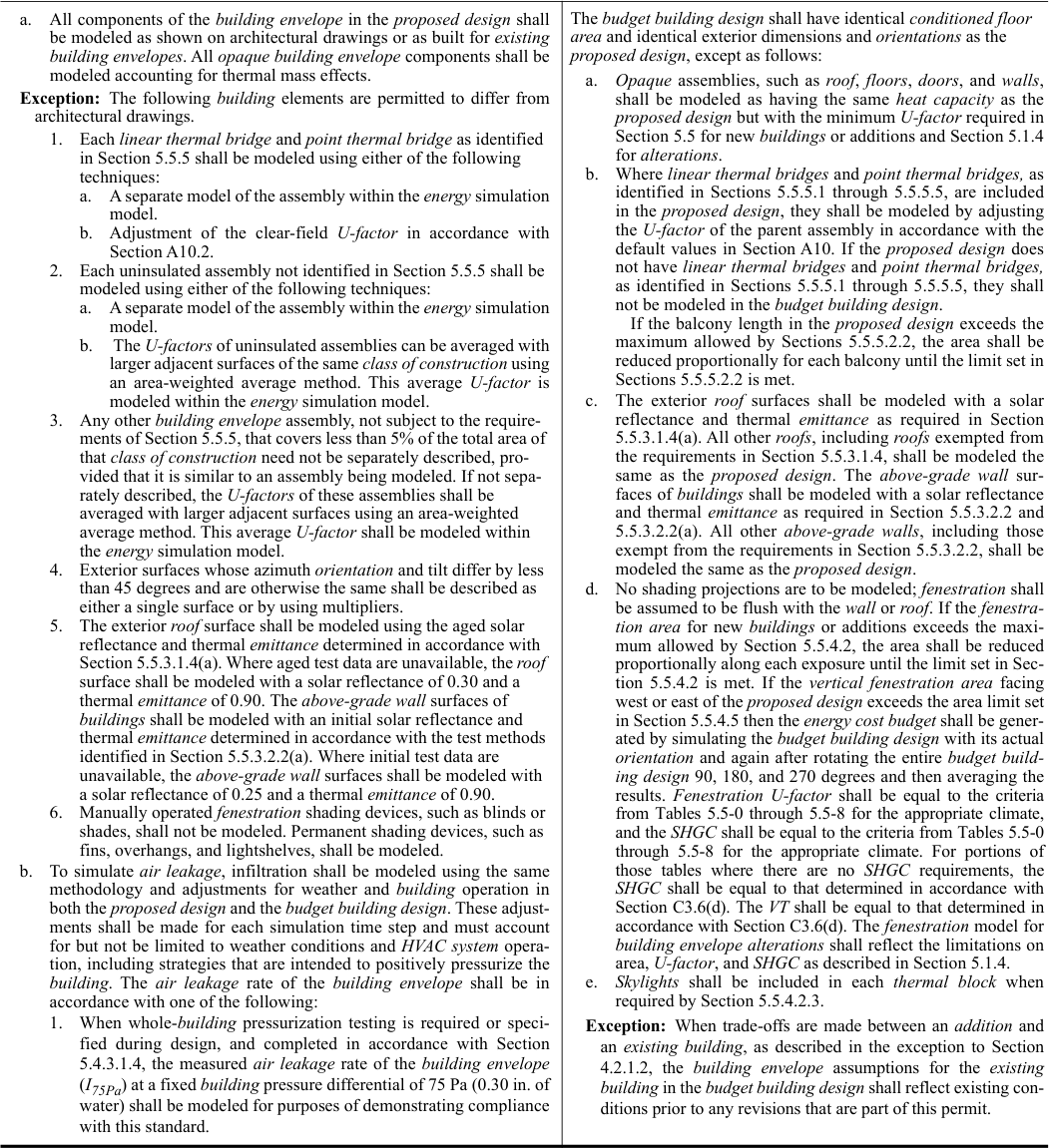
- All components of the building envelope in the proposed design shall be modeled as shown on architectural drawings or as built for existing building envelopes. All opaque building envelope components shall be modeled accounting for thermal mass effects.
Exception: The following building elements are permitted to differ from architectural drawings.
- Each linear thermal bridge and point thermal bridge as identified in Section 5.5.5 shall be modeled using either of the following techniques:
- A separate model of the assembly within the energy simulation model.
- Adjustment of the clear-field U-factor in accordance with Section A10.2.
- Each uninsulated assembly not identified in Section 5.5.5 shall be modeled using either of the following techniques:
- A separate model of the assembly within the energy simulation model.
- The U-factors of uninsulated assemblies can be averaged with larger adjacent surfaces of the same class of construction using an area-weighted average method. This average U-factor is modeled within the energy simulation model.
- Any other building envelope assembly, not subject to the requirements of Section 5.5.5, that covers less than 5% of the total area of that class of construction need not be separately described, provided that it is similar to an assembly being modeled. If not separately described, the U-factors of these assemblies shall be averaged with larger adjacent surfaces using an area-weighted average method. This average U-factor shall be modeled within the energy simulation model.
- Exterior surfaces whose azimuth orientation and tilt differ by less than 45 degrees and are otherwise the same shall be described as either a single surface or by using multipliers.
- The exterior roof surface shall be modeled using the aged solar reflectance and thermal emittance determined in accordance with Section 5.5.3.1.4(a). Where aged test data are unavailable, the roof surface shall be modeled with a solar reflectance of 0.30 and a thermal emittance of 0.90. The above-grade wall surfaces of buildings shall be modeled with an initial solar reflectance and thermal emittance determined in accordance with the test methods identified in Section 5.5.3.2.2(a). Where initial test data are unavailable, the above-grade wall surfaces shall be modeled with a solar reflectance of 0.25 and a thermal emittance of 0.90.
- Manually operated fenestration shading devices, such as blinds or shades, shall not be modeled. Permanent shading devices, such as fins, overhangs, and lightshelves, shall be modeled.
- To simulate air leakage, infiltration shall be modeled using the same methodology and adjustments for weather and building operation in both the proposed design and the budget building design. These adjustments shall be made for each simulation time step and must account for but not be limited to weather conditions and HVAC system operation, including strategies that are intended to positively pressurize the building. The air leakage rate of the building envelope shall be in accordance with one of the following:
- When whole-building pressurization testing is required or specified during design, and completed in accordance with Section 5.4.3.1.4, the measured air leakage rate of the building envelope (I75Pa) at a fixed building pressure differential of 75 Pa (0.30 in. of water) shall be modeled for purposes of demonstrating compliance with this standard.
|
The budget building design shall have identical conditioned floor area and identical exterior dimensions and orientations as the proposed design, except as follows:
- Opaque assemblies, such as roof, floors, doors, and walls, shall be modeled as having the same heat capacity as the proposed design but with the minimum U-factor required in Section 5.5 for new buildings or additions and Section 5.1.4 for alterations.
- Where linear thermal bridges and point thermal bridges, as identified in Sections 5.5.5.1 through 5.5.5.5, are included in the proposed design, they shall be modeled by adjusting the U-factor of the parent assembly in accordance with the default values in Section A10. If the proposed design does not have linear thermal bridges and point thermal bridges, as identified in Sections 5.5.5.1 through 5.5.5.5, they shall not be modeled in the budget building design.
If the balcony length in the proposed design exceeds the maximum allowed by Sections 5.5.5.2.2, the area shall be reduced proportionally for each balcony until the limit set in Sections 5.5.5.2.2 is met.
- The exterior roof surfaces shall be modeled with a solar reflectance and thermal emittance as required in Section 5.5.3.1.4(a). All other roofs, including roofs exempted from the requirements in Section 5.5.3.1.4, shall be modeled the same as the proposed design. The above-grade wall surfaces of buildings shall be modeled with a solar reflectance and thermal emittance as required in Section 5.5.3.2.2 and 5.5.3.2.2(a). All other above-grade walls, including those exempt from the requirements in Section 5.5.3.2.2, shall be modeled the same as the proposed design.
- No shading projections are to be modeled; fenestration shall be assumed to be flush with the wall or roof. If the fenestration area for new buildings or additions exceeds the maximum allowed by Section 5.5.4.2, the area shall be reduced proportionally along each exposure until the limit set in Section 5.5.4.2 is met. If the vertical fenestration area facing west or east of the proposed design exceeds the area limit set in Section 5.5.4.5 then the energy cost budget shall be generated by simulating the budget building design with its actual orientation and again after rotating the entire budget building design 90, 180, and 270 degrees and then averaging the results. Fenestration U-factor shall be equal to the criteria from Tables 5.5-0 through 5.5-8 for the appropriate climate, and the SHGC shall be equal to the criteria from Tables 5.5-0 through 5.5-8 for the appropriate climate. For portions of those tables where there are no SHGC requirements, the SHGC shall be equal to that determined in accordance with Section C3.6(d). The VT shall be equal to that determined in accordance with Section C3.6(d). The fenestration model for building envelope alterations shall reflect the limitations on area, U-factor, and SHGC as described in Section 5.1.4.
- Skylights shall be included in each thermal block when required by Section 5.5.4.2.3.
Exception: When trade-offs are made between an addition and an existing building, as described in the exception to Section 4.2.1.2, the building envelope assumptions for the existing building in the budget building design shall reflect existing conditions prior to any revisions that are part of this permit.
|