ASHRAE-90.1-2022- - Full Extract
PDF Page 1

ANSI/ASHRAE/IES Standard 90.1-2022
(Supersedes ANSI/ASHRAE/IES Standard 90.1-2019) Includes ANSI/ASHRAE/IES addenda listed in Appendix M
Energy Standard for Sites and Buildings
Except Low-Rise Residential Buildings
(I-P Edition)
See Informative Appendix M for dates of approval by ASHRAE, the Illuminating Engineering Society, and the American National Standards Institute.
This Standard is under continuous maintenance by a Standing Standard Project Committee (SSPC) for which the Standards Committee has established a documented program for regular publication of addenda or revisions, including procedures for timely, documented, consensus action on requests for change to any part of the Standard. Instructions for how to submit a change can be found on the ASHRAE [®] website (www.ashrae.org/continuous-maintenance).
The latest edition of an ASHRAE Standard may be purchased from the ASHRAE website (www.ashrae.org) or from ASHRAE Customer Service, 180 Technology Parkway, Peachtree Corners, GA 30092. E-mail: orders@ashrae.org. Fax: 678-539-2129. Telephone: 404-636-8400 (worldwide), or toll free 1-800-527-4723 (for orders in US and Canada). For reprint permission, go to www.ashrae.org/permissions.
© 2022 ASHRAE ISSN 1041-2336



PDF Page 2
ASHRAE Standard Project Committee 90.1 (2019–2022)
Cognizant TC: 7.6 Systems Energy Utilization SPLS Liaison: Jennifer Isenbeck · ASHRAE Staff Liaison: Emily Toto · IES Liaison: Mark Lien
Donald Brundage, Chair Phillip Gentry Andrew Klein Loren Ross Thomas Culp, Co-Vice Chair Jason Glazer Vladimir Kochkin Robert Ross Richard Lord, Co-Vice Chair Melissa Goren Michael Lane Marty Salzberg Rahul Athalye Krishnan Gowri Toby Lau Christopher Schaffner William Babbington Patricia Graef Chonghui Liu Greg Schluterman John Bade Mark Graham Emily Lorenz Amy Schmidt Sean Beilman Aaron Gunzner Joel Martell Leonard Sciarra Kyle Bergeron Pekka Hakkarainen Samuel Mason Kelly Seeger Jeffrey Boldt David Handwork Christopher Mathis Sean Smith Joseph Brooks Armin Hauer Merle McBride Wayne Stoppelmoor Scott Campbell Rick Heiden James McClendon Matthew Swenka Elizabeth Cassin Gary Heikkinen Benjamin Meyer Christian Taber Paula Cino Mark Heizer Darren Meyers William Talbert Glen Clapper David Herron Harry Misuriello Steven Taylor Ernest Conrad Scott Hintz James (Mike) Moore Michael Tillou Shannon Corcoran Emily Hoffman Frank Morrison Douglas Tucker Charles Cottrell Mike Houston Michael Myer Jason Vandever Jay Crandell Jonathan Humble Frank Myers Martha VanGeem Brandon Damas Michael Ivanovich Michael Patterson Michael Waite Julie Donovan Harold Jepsen Timothy Peglow McHenry Wallace Craig Drumheller Chad Johnson Tien Peng Helen Walter-Terrinoni John Dunlap Greg Johnson Christopher Perry Richard Watson James Earley Duane Jonlin Laura Petrillo-Groh Jerry White Drake Erbe Michael Jouaneh Catherine Rivest Jeremiah Williams D. Andrew Fouss Hyman Kaplan Michael Rosenberg Amber Wood Sam Francis Maria Karpman Steven Rosenstock
ASHRAE STANDARDS COMMITTEE 2022–2023
Susanna S. Hanson, Chair Phillip A. Johnson Lawrence C. Markel Christopher J. Seeton Jonathan Humble, Vice-Chair Srinivas Katipamula Patrick C. Marks Christian R. Taber William P. Bahnfleth Gerald J. Kettler Margaret M. Mathison Paolo M. Tronville Thomas E. Cappellin Jay A. Kohler Kathleen Owen William F. Walter Douglas D. Fick Cesar L. Lim Gwelen Paliaga Steven C. Sill, BOD ExO Patricia Graef Paul A. Lindahl, Jr. Karl L. Peterman Sarah E. Maston, CO Jaap Hogeling James D. Lutz Justin M. Prosser Jennifer A. Isenbeck Julie Majurin David Robin
Connor Barbaree, Senior Manager of Standards
SPECIAL NOTE This American National Standard (ANS) is a national voluntary consensus Standard developed under the auspices of ASHRAE. Consensus is defined by the American National Standards Institute (ANSI), of which ASHRAE is a member and which has approved this Standard as an ANS, as “substantial agreement reached by directly and materially affected interest categories. This signifies the concurrence of more than a simple majority, but not necessarily unanimity. Consensus requires that all views and objections be considered, and that an effort be made toward their resolution.” Compliance with this Standard is voluntary until and unless a legal jurisdiction makes compliance mandatory through legislation.
ASHRAE obtains consensus through participation of its national and international members, associated societies, and public review. ASHRAE Standards are prepared by a Project Committee appointed specifically for the purpose of writing the Standard. The Project Committee Chair and Vice-Chair must be members of ASHRAE; while other committee members may or may not be ASHRAE members, all must be technically qualified in the subject area of the Standard. Every effort is made to balance the concerned interests on all Project Committees.
The Senior Manager of Standards of ASHRAE should be contacted for
a. interpretation of the contents of this Standard, b. participation in the next review of the Standard, c. offering constructive criticism for improving the Standard, or d. permission to reprint portions of the Standard.
DISCLAIMER ASHRAE uses its best efforts to promulgate Standards and Guidelines for the benefit of the public in light of available information and accepted industry practices. However, ASHRAE does not guarantee, certify, or assure the safety or performance of any products, components, or systems tested, installed, or operated in accordance with ASHRAE’s Standards or Guidelines or that any tests conducted under its Standards or Guidelines will be nonhazardous or free from risk.
ASHRAE INDUSTRIAL ADVERTISING POLICY ON STANDARDS ASHRAE Standards and Guidelines are established to assist industry and the public by offering a uniform method of testing for rating purposes, by suggesting safe practices in designing and installing equipment, by providing proper definitions of this equipment, and by providing other information that may serve to guide the industry. The creation of ASHRAE Standards and Guidelines is determined by the need for them, and conformance to them is completely voluntary. In referring to this Standard or Guideline and in marking of equipment and in advertising, no claim shall be made, either stated or implied, that the product has been approved by ASHRAE.
PDF Page 3
CONTENTS
ANSI/ASHRAE/IES Standard 90.1-2022 Energy Standard for Sites and Buildings Except Low-Rise Residential Buildings (I-P Edition)
SECTION PAGE
Foreword …2
1 Purpose…3
2 Scope…3
3 Definitions, Abbreviations, and Acronyms…4
4 Administration and Enforcement…36
5 Building Envelope …42
6 Heating, Ventilating, and Air Conditioning…71
7 Service Water Heating …137
8 Power…144
9 Lighting…148
10 Other Equipment …172
11 Additional Efficiency Requirements…181
12 Energy Cost Budget Method …208
13 Normative References…223
Normative Appendix A: Rated R-Value of Insulation and Assembly U-Factor, C-Factor, and
F-Factor Determinations …229
Informative Appendix B: (Retained for Future Use) …282
Normative Appendix C: Methodology for Building Envelope Trade-Off Option in Section 5.6…283
Informative Appendix D: (Retained for Future Use) …290
Informative Appendix E: Informative References…291
Informative Appendix F: U.S. Department of Energy Minimum Energy Efficiency Requirements,
Test Procedures, and Definitions…295
Normative Appendix G: Performance Rating Method …301
Informative Appendix H: Additional Guidance for Verification, Testing, and Commissioning …345
Informative Appendix I: Using Other Metrics in Conjunction with
Appendix G Performance Rating Method when Approved by the Rating Authority…354
Normative Appendix J: Sets of Performance Curves…360
Informative Appendix K: Informative Figures—Thermal Bridges …367
Normative Appendix L: Mechanical System Performance Rating Method…372
Informative Appendix M: Addenda Description …393
Annex 1: Reference Standard Reproduction—ASHRAE Standard 169…399
NOTE
Approved addenda, errata, or interpretations for this standard can be downloaded free of charge from the ASHRAE website at www.ashrae.org/technology.
© 2022 ASHRAE 180 Technology Parkway NW · Peachtree Corners, GA 30092 · www.ashrae.org · All rights reserved. ASHRAE is a registered trademark of the American Society of Heating, Refrigerating and Air-Conditioning Engineers, Inc.
ANSI is a registered trademark of the American National Standards Institute.
PDF Page 4
(This foreword is not part of this standard. It is merely informative and does not contain requirements necessary for conformance to the standard. It has not been processed according to the ANSI require- ments for a standard and may contain material that has not been subject to public review or a consen- sus process. Unresolved objectors on informative material are not offered the right to appeal at ASHRAE or ANSI.)
FOREWORD
The 2022 edition of Standard 90.1 incorporates more than 80 addenda to the 2019 edition and includes numerous energy-saving measures. Notable changes include the following:
General
includes exceptions for small buildings, buildings with limited roof space, and other situations where PV installations would be problematic.
• It should be noted that, due to the addition of a new section and several appendices, the number or letter designations of several well-known sections and appendices have changed from those used in the 2019 and previous editions of the standard.
Administration and Enforcement
• There were no major changes to administration and enforcement.
• Requirements were added that address the impacts of thermal bridges in building envelopes, with a new Informative Appendix K providing supplemental information on application.
• A solar reflectance requirement for walls was added for Climate Zone 0. This is similar to the require- ments for high albedo roofs.
• Specific provisions were added to distinguish roof replacements from other types of alterations.
• A ne w reference was added for steel-framed walls to allow use of ANSI /AISI S250 for U-factor determi- nation.
• Added a definition for insulated metal panels (IMPs).
• Normative Appendix A was reformatted to clarify the requirements for thermal performance calculations.
Lighting and Power
• Reorganized Section 9, “Lighting,” to be more consistent with the structure of other main sections of the standard.
• Updated installed interior lighting power allowances and minimum control requirements; added a power exception for the germicidal function in luminaires and sources; and removed exceptions for casinos and parking garage daylight transition zone lighting.
• Modified a number of lighting requirements to reflect greater use of higher efficiency LED products and revised lighting practices.
• Added requirements for indoor horticultural lighting in greenhouses and indoor grow buildings based on a new metric, photosynthetic photon efficacy (PPE), developed in ANSI/ASABE S640.
• Provided an additional interior lighting power allowance for video conferencing. Power allowances and controls have been moved to a table for ease of reference.
2 ANSI/ASHRAE/IES Standard 90.1-2022 (I-P)

PDF Page 5
Mechanical
• Introduced an optional Mechanical System Performance Path that allows HVAC system efficiency trade- offs based on a new metric, total system performance ratio (TSPR).
• Required condensing boilers for new construction in order to achieve 90% or greater efficiency for large boilers (1 to 10 million Btuh. The thermal efficiency requirements for high-capacity gas-fired service water-heating equipment were also increased.
• Established a minimum enthalpy recovery ratio for energy recovery systems and specified operational requirements to ensure proper economized performance.
• Revised demand control ventilation requirements to be based on climate zone and Standard 62.1 airflow requirements.
• Modified the minimum efficiency requirements for air-source heat pumps and introduced a new metric, COPHR, for units that perform heat recovery during chiller operation.
• Added the minimum energy efficiency requirements (and new CFEI metric) for large-diameter ceiling fans from 10 CFR 430.
Performance Rating Method (Appendix G)
• New requirements were added to limit trade-offs between the building envelope and other building systems.
• A new Informative Appendix I was added that provides information on how alternative performance met- rics other than cost could be used with the Performance Rating Method. These alternative metrics include site energy, source energy, and carbon emissions, and would be useful to assess building performance against carbon emission goals or for similar types of comparison.
• A relaxation in stringency was added when using Normative Appendix G for retrofit projects consisting of substantial alterations.
Both Performance-Based Compliance Paths (Section 12 [Energy Cost Budget Method] and Appendix G)
• Numerous changes were included to improve clarity and coordinate with revisions to other sections of the standard.
New Normative Appendix J
• Contains performance curves that represent minimally compliant chiller performance for the budget and baseline building design and for proposed building designs when specific equipment performance is not known.
- PURPOSE + 2. SCOPE: NOT ADOPTED BY OREGON PER 2024 OEESC E102.3.2.
ANSI/ASHRAE/IES Standard 90.1-2022 (I-P) 3
THEREFORE 3 STORY MULTIFAMILY IS UNDER THIS CODE?
1
PDF Page 6
2.2 The provisions of this standard do not apply to
a. single-family houses and related incidental structures, multifamily structures of three stories or fewer
above grade, manufactured houses (mobile homes), and manufactured houses (modular) or b. buildings that use neither electricity nor fossil fuel .
2.3 Where specifically noted in this standard, certain other buildings or elements of buildings or sites shall be exempt.
2.4 This standard shall not be used to circumvent any safety, health, or environmental requirements.
3. DEFINITIONS, ABBREVIATIONS, AND ACRONYMS
3.1 General. Certain terms, abbreviations, and acronyms are defined in this section for the purposes of this standard. When the tense or plurality of the term is different than the defined term, the definition still applies. These definitions are applicable to all sections of this standard, wherever italicized . Terms that are not italicized shall have their ordinarily accepted meanings within the context in which they are used. Ordinarily accepted meanings shall be based on American standard English language usage as documented in an unabridged dictionary accepted by the adopting authority .
3.2 Definitions
above-grade wall: see wall .
access hatch: see door .
addition: an extension or increase in floor area or height of a building outside of the existing building enve- lope or the equipment or systems to a site .
adopting authority: the agency or agent that adopts this standard.
air economizer: see economizer, air .
air leakage: the uncontrolled airflow through the building envelope caused by pressure differences across the building envelope due to factors such as wind, inside and outside temperature differences, stack effect, and imbalance between supply and exhaust air systems . Air leakage can move inward (infiltration) or outward (exfiltration) through the building envelope .
air system balancing: see balancing, air system .
alteration: replacing or adding to systems, equipment, structures, or building assemblies; routine maintenance, repair, and service, or a change in the building or structure use classification or space conditioning category shall not constitute an alteration .
annual fuel utilization efficiency (AFUE): an efficiency descriptor of the ratio of annual output energy to annual input energy as developed in accordance with the requirements of U.S. Department of Energy (DOE) 10 CFR Part 430.
attic and other roofs: see roof .
authority having jurisdiction: the agency or agent responsible for enforcing this standard.
automatic or automatically: self-acting, operating by its own mechanism when actuated by some nonmanual influence, such as a change in current strength, pressure, temperature, or mechanical configuration.
automatic control device: a device capable of automatically turning loads off and on without manual intervention.
balancing, air system: adjusting airflow rates through air distribution system devices, such as fans and diffusers, by manually adjusting the position of dampers, splitter vanes, extractors, etc., or by using automatic control devices such as constant-air-volume or variable-air-volume (VAV) boxes.
balancing, hydronic system: adjusting water flow rates through hydronic distribution system devices, such as pumps and coils, by manually adjusting the position valves or by using automatic control devices such as automatic flow control valves.
ballast: a device used in conjunction with an electric-discharge lamp to cause the lamp to start and operate under the proper circuit conditions of voltage, current, wave form, electrode heat, etc.
baseline building design: a computer representation of a hypothetical design based on the proposed design . This representation is used as the basis for calculating the baseline building performance for rating abovestandard design or when using the Performance Rating Method as an alternative path for minimum standard compliance in accordance with Section 4.2.1.1.
4 ANSI/ASHRAE/IES Standard 90.1-2022 (I-P)
PDF Page 7
baseline building performance: the annual energy cost for a building design intended for use as a baseline for rating above-standard design or when using the Performance Rating Method as an alternative path for minimum standard compliance in accordance with Section 4.2.1.1.
below-grade wall: see wall .
best efficiency point (BEP): the pump hydraulic power operating point (consisting of both flow and head conditions) that results in the maximum efficiency .
boiler: a self-contained, low-pressure appliance for supplying steam or hot water.
modulating boiler: a boiler that is capable of more than a single firing rate in response to a varying temperature or heating load. packaged boiler: a boiler that is shipped complete with heating equipment, mechanical draft equipment, and automatic controls, and that is usually shipped in one or more sections. A packaged boiler includes factory-built boilers manufactured as a unit or system, disassembled for shipment, and reassembled at the site .
boiler system: one or more boilers and their piping and controls that work together to supply steam or hot water to heat output devices remote from the boiler .
branch circuit: the circuit conductors between the final overcurrent device protecting the circuit and the outlets; the final wiring run to the load.
bubble point: the refrigerant liquid saturation temperature at a specified pressure.
budget building design: a computer representation of a hypothetical design based on the actual proposed design . This representation is used as the basis for calculating the energy cost budget .
building: any structure used or intended for supporting or sheltering any use or occupancy.
building entrance: any doorway, set of doors, revolving door, vestibule, or other form of portal that is ordinarily used to gain access to the building or to exit from the building by its users and occupants. This does not include doors solely used to directly enter mechanical, electrical, and other building utility service equipment rooms.
building envelope: the exterior plus the semiexterior portions of a building . For the purposes of determining building envelope requirements, the classifications are defined as follows:
exterior building envelope: the elements of a building that separate conditioned spaces from the exterior. semiexterior building envelope: the elements of a building that separate conditioned space from uncon- ditioned space or that enclose semiheated spaces through which thermal energy may be transferred to or from the exterior, to or from unconditioned spaces, or to or from conditioned spaces .
building envelope trade-off schedules and loads: the schedules and internal loads [1], by building area type, to be used in the building envelope trade-off option simulations described in Normative Appendix C.
building material: any element of the building envelope, other than air films and insulation, through which heat flows and that is included in the component U-factor calculations.
building official: the officer or other designated authority having jurisdiction charged with the administration and enforcement of this standard, or a duly authorized representative.
building service: the equipment for delivering energy from the supply or distribution system to the premises served.
building service equipment: the necessary equipment, usually consisting of a circuit breaker or switch and fuses and accessories, located near the point of entrance of supply conductors to a building or other structure (or an otherwise defined area) and intended to constitute the main control and means of cutoff of the supply. Service equipment may consist of circuit breakers or fused switches provided to disconnect all undergrounded conductors in a building or other structure from the service-entrance conductors.
C-factor: see thermal conductance .
ceiling fan: a nonportable ( permanently installed ) device suspended from a ceiling or overhead structure for circulating air via the rotation of fan blades.
ceiling fan energy index (CFEI): the ratio of the electric input power of a reference ceiling fan to the electric input power of the actual ceiling fan as calculated per AMCA 208 with the following modifications to
- Schedules and internal loads by building area type are at https://web.ashrae.org/90_1files.
ANSI/ASHRAE/IES Standard 90.1-2022 (I-P) 5
PDF Page 8
the calculations for the reference fan: using an airflow constant ( Q 0) of 26,500 cfm, a pressure constant ( P 0) of 0.002700 in. of water, and a fan efficiency constant (η0) of 42%.
ceiling fan, large diameter: a ceiling fan that is greater than or equal to 84.5 in. in diameter.
chi-factor (χ or Chi): thermal transmittance of a point thermal bridge in units of Btu/(h·°F).
circuit breaker: a device designed to open and close a circuit by nonautomatic means and to open the circuit automatically at a predetermined overcurrent without damage to itself when properly applied within its rating.
class of construction: for the building envelope, a subcategory of roof, above-grade wall, below-grade wall, floor, slab-on-grade floor, opaque door, vertical fenestration, or skylight . (See roof, wall, floor, slab-on- grade floor, door, and fenestration .)
clear-field thermal bridge: see thermal bridge.
code official: see building official.
coefficient of performance (COPH), heat pump—heating: the ratio of the rate of heat delivered to the rate of energy input, in consistent units, for a complete heat-pump system, including the compressor and, if applicable, auxiliary heat, under designated operating conditions.
combined energy efficiency ratio (CEER): a ratio of the total cooling one year divided by the total energy from active, standby, and OFF modes as specified in 10 CFR 430.23.
commissioning: a quality-focused process for enhancing the delivery of a project for verifying and documenting that the building and its systems, controls, and building envelope are planned, designed, installed, tested, and include plans for operation and maintenance to meet specified requirements.
commissioning provider: an entity who manages the commissioning team to implement building commis- sioning .
computer room: a room whose primary function is to house equipment for the processing and storage of electronic data and that has a design electronic data equipment power density exceeding 20 W/ft [2] of conditioned floor area.
computer room energy: annual energy use of the data center, including all IT equipment energy, plus energy that supports the IT equipment and computer room space, calculated in accordance with industry-accepted standards defined as Total Annual Energy (see Informative Appendix E).
condensing unit: a factory-made assembly of refrigeration components designed to compress and liquefy a specific refrigerant. It consists of one or more refrigerant compressors, refrigerant condensers (air-cooled, evaporatively cooled, and/or water-cooled), condenser fans and motors (where used), and factory-supplied accessories.
conditioned floor area, gross: see floor area, gross .
conditioned space: see space.
construction: the fabrication and erection of a new building or any addition to or alteration of an existing building .
construction documents: drawings and specifications used to construct, add to, or alter building s, systems, or equipment, or portions thereof.
continuous air barrier: the combination of interconnected materials, assemblies, and sealed joints and components of the building envelope that minimize air leakage into or out of the building envelope .
continuous daylight dimming: method of automatic lighting control using daylight photosensors, where the lights are dimmed continuously, or using at least four preset levels with at least a five-second fade between levels, where the control turns the lights off when sufficient daylight is available.
continuous dimming: a lighting control strategy that varies the light output of a lighting system over a continuous range from full light output to a minimum light output in imperceptible steps without flickering.
control: to regulate the operation of equipment . ( Informative Note: This definition is not applicable to the use of this word as a noun to describe a combination of control devices and software, used to achieve control of HVAC, lighting, or other equipment or systems .)
control device: a specialized device used to regulate the operation of equipment .
6 ANSI/ASHRAE/IES Standard 90.1-2022 (I-P)
PDF Page 9
cooldown: reduction of space temperature down to occupied set point after a period of shutdown or setup.
cooled space: see space, conditioned space .
cooling degree-day, base (CDD): see degree-day.
cooling design temperature: the outdoor dry-bulb temperature equal to the temperature that is exceeded by 1% of the number of hours during a typical weather year.
critical circuit: the hydronic circuit that determines the minimum differential pressure that the pump must produce to satisfy the zone loads (e.g., the circuit with the most-open valve). The critical circuit is the one with the highest pressure drop required to satisfy its load. At part-load conditions, the critical circuit can change based on zone loads.
daylight area: the floor area substantially illuminated by daylight.
daylight area under roof monitors: the daylight area under roof monitors is the combined daylight area under each roof monitor within each space . The daylight area under each roof monitor is the product of
a. the width of the vertical fenestration above the ceiling level plus, on each side, the smallest of
- 2 ft,
- the distance to any 5 ft or higher vertical obstruction, or
- the distance to the edge of any primary sidelighted area and b. the smaller of the following horizontal distances inward from the bottom edge of the vertical fenes-
tration (see Figure 3.2-1):
- The monitor sill height (MSH) (the vertical distance from the floor to the bottom edge of the monitor glazing)
- The distance to the nearest face of any opaque vertical obstruction, where any part of the obstruction is farther away than the difference between the height of the obstruction and the monitor sill height (MSH – OH) daylight area under skylights: the daylight area under skylights is the combined daylight area under each skylight within a space . The daylight area under each skylight is bounded by the opening beneath the skylight and horizontally in each direction (see Figure 3.2-2), the smaller of
a. 70% of the ceiling height (0.7 × CH) or b. the distance to the nearest face of any opaque vertical obstruction, where any part of the obstruction
is farther away than 70% of the distance between the top of the obstruction and the ceiling (0.7 ×
[CH – OH], where CH = the height of the ceiling at the lowest edge of the skylight, and OH = the height to the top of the obstruction). daylight area under skylights in multistory spaces: the daylight area under skylights in multistory spaces shall include floor areas directly beneath the skylight and portions of the uppermost floor adjacent to the multistory space that meet the criteria for a daylight area under skylights, where CH is the ceiling height of the uppermost floor (see Figure 3.2-3). primary sidelighted area: the total primary sidelighted area is the combined primary sidelighted area within each space . Each primary sidelighted area is directly adjacent to vertical fenestration in an exterior wall below the ceiling (see Figure 3.2-4).
a. The primary sidelighted area width is the width of the vertical fenestration plus, on each side, the
smaller of
- one half of the vertical fenestration head height (where head height is the distance from the floor to the top of the glazing) or
- the distance to any 5 ft or higher opaque vertical obstruction. b. The primary sidelighted area depth is the horizontal distance perpendicular to the vertical fenes-
tration, which is the smaller of
- one vertical fenestration head height or
- the distance to any 5 ft or higher opaque vertical obstruction. secondary sidelighted area: the total secondary sidelighted area is the combined secondary sidelighted area within a space . Each secondary sidelighted area is directly adjacent to a primary sidelighted area (see Figure 3.2-5):
a. The secondary sidelighted area width is the width of the vertical fenestration plus, on each side,
the smaller of
- one half of the vertical fenestration head height or
- the distance to any 5 ft or higher opaque vertical obstruction.
ANSI/ASHRAE/IES Standard 90.1-2022 (I-P) 7
PDF Page 10
b. The secondary sidelighted area depth is the horizontal distance perpendicular to the vertical fenes-
tration, which begins at the edge of the primary sidelighted area depth and ends at the smaller of
- one vertical fenestration head height or
- the distance to any 5 ft or higher opaque vertical obstruction.
If the adjacent primary sidelighted area ends at a 5 ft or higher opaque vertical obstruction, there is no secondary sidelighted area beyond such obstruction.
dead band: the range of values within which a sensed variable can vary without initiating a change in the controlled process.
decorative lighting: see lighting, decorative .
dedicated replacement air: see makeup air .
degree-day: the difference in temperature between the outdoor mean temperature over a twenty-four-hour period and a given base temperature. The classifications are defined as follows:
cooling degree-day base 50°F (CDD50): for any one day, when the mean temperature is more than 50°F, there are as many degree-days as degrees Fahrenheit temperature difference between the mean temperature for the day and 50°F. Annual cooling degree-days ( CDDs ) are the sum of the degree-days over a calendar year. heating degree-day base 65°F (HDD65): for any one day, when the mean temperature is less than 65°F, there are as many degree-days as degrees Fahrenheit temperature difference between the mean temperature for the day and 65°F. Annual heating degree-days (HDDs) are the sum of the degree-days over a calendar year.
demand: the highest amount of power (average Btu/h over an interval) recorded for a building or facility in a selected time frame.
demand control ventilation (DCV): a ventilation system capability that provides for the automatic reduction of outdoor air intake below design rates when the actual occupancy of spaces served by the system is less than design occupancy.
design capacity: output capacity of a system or piece of equipment at design conditions .
design conditions: specified environmental conditions, such as temperature and light intensity, required to be produced and maintained by a system and under which the system must operate.
design energy cost: the annual energy cost calculated for a proposed design .
design professional: an architect or engineer licensed to practice in accordance with applicable state licensing laws.
dimmer: a lighting control device that is capable of varying the light output and energy usage of light sources.
direct digital control (DDC): a type of control where controlled and monitored analog or binary data (e.g., temperature, contact closures) are converted to digital format for manipulation and calculations by a digital computer or microprocessor and then converted back to analog or binary form to control physical devices.
distribution system: conveying means, such as ducts, pipes, and wires, to bring substances or energy from a source to the point of use. The distribution system includes such auxiliary equipment as fans, pumps, and transformers .
door: an operable opening area in the building envelope that is not fenestration . A door where more than one-half of the door area is glazed is considered fenestration, and a door where one-half or less of the door area is glazed is considered an opaque door . An access hatch is considered a door . For the purposes of determining building envelope requirements, the classifications are defined as follows:
metal coiling door: an upward-acting, nonswinging door assembly consisting of interlocking horizontal slats or sheets that, upon opening the door, roll up around a horizontal barrel above the door opening. nonswinging door: roll-up, metal coiling, sliding, and any other door that is not a swinging door . sectional garage door: an upward-acting, nonswinging door assembly made of two or more horizontal panels hinged together vertically. swinging door: a door having an operable opaque panel with hinges or pivots on one side.
door area: total area of the door measured using the rough opening and including the door slab and the frame. (See fenestration area .)
driver: a device designed to operate a solid-state (e.g., LED) light source.
8 ANSI/ASHRAE/IES Standard 90.1-2022 (I-P)
PDF Page 11
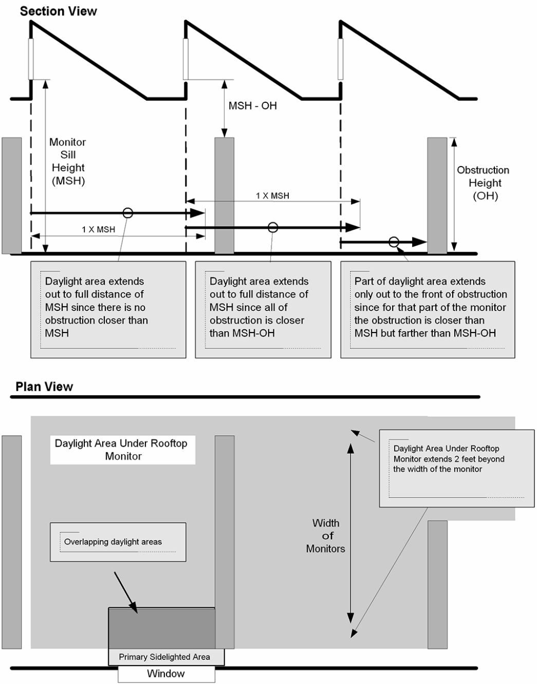
Figure 3.2-1 Computing the daylight area under roof monitors.
ANSI/ASHRAE/IES Standard 90.1-2022 (I-P) 9
PDF Page 12
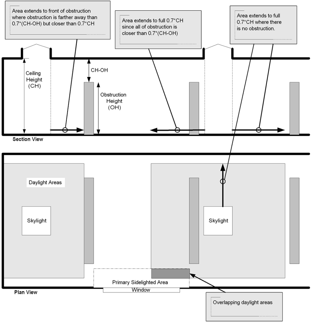
Figure 3.2-2 Computing the daylight area under skylights.
10 ANSI/ASHRAE/IES Standard 90.1-2022 (I-P)
PDF Page 13

Figure 3.2-3 Computing the daylight area under skylights in multistory spaces.
ANSI/ASHRAE/IES Standard 90.1-2022 (I-P) 11
PDF Page 14
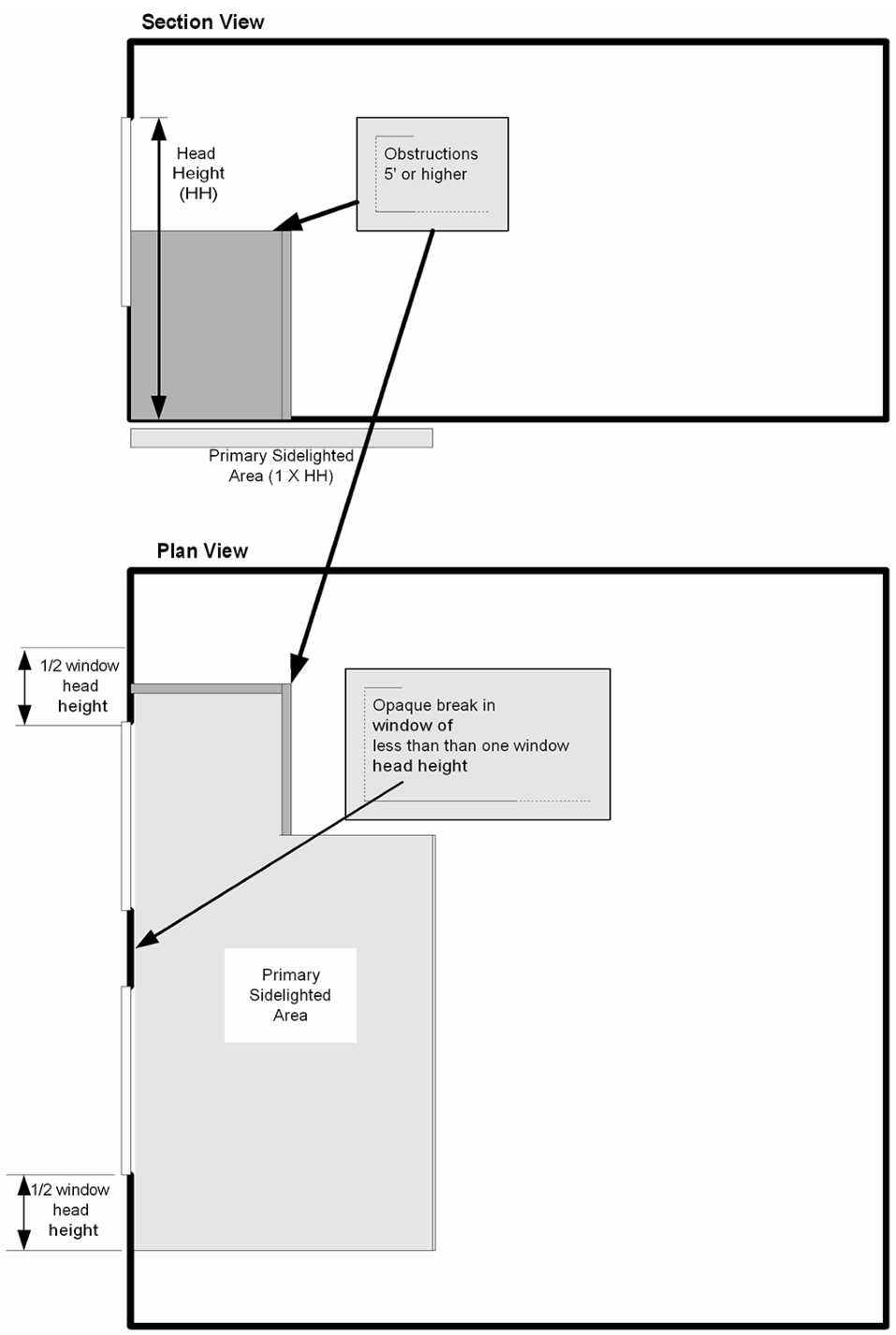
Figure 3.2-4 Computing the primary sidelighted area.
12 ANSI/ASHRAE/IES Standard 90.1-2022 (I-P)
PDF Page 15
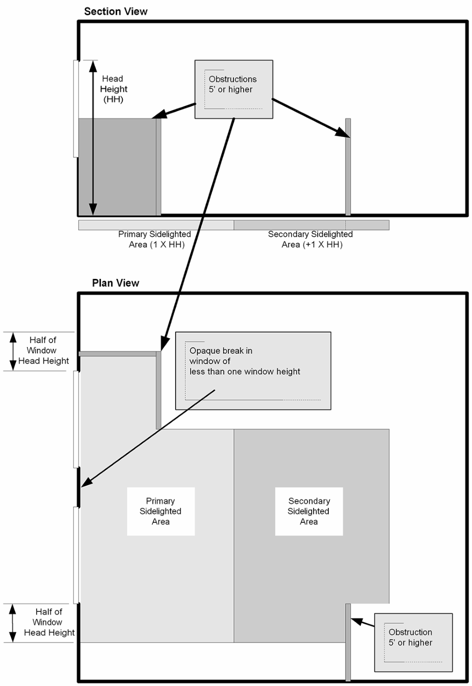
Figure 3.2-5 Computing the secondary sidelighted area.
ANSI/ASHRAE/IES Standard 90.1-2022 (I-P) 13
PDF Page 16
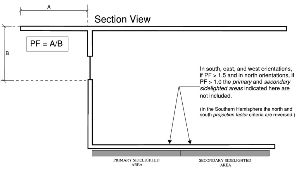
Figure 3.2-6 Computing the primary and secondary sidelighted areas with external projections.
14 ANSI/ASHRAE/IES Standard 90.1-2022 (I-P)
PDF Page 17
ductwork: a system of ducts for distribution and extraction of air.
dwelling unit: a single unit providing complete independent living facilities for one or more persons, including permanent provisions for living, sleeping, eating, cooking, and sanitation.
direct-expansion dedicated outdoor air system units (DX-DOAS units): a type of air-cooled, water-cooled, or water-source factory-assembled product that dehumidifies 100% outdoor air to a low dew point and includes reheat that is capable of controlling the supply dry-bulb temperature of the dehumidified air to the designed supply air temperature. This conditioned outdoor air is then delivered directly or indirectly to the conditioned spaces . It may precondition outdoor air by containing an enthalpy wheel, sensible wheel, desiccant wheel, plate heat exchanger, heat pipes, or other heat or mass transfer apparatus.
dynamic glazing: any glazing system /glazing infill that has the fully reversible ability to change its performance properties, including U-factor, solar heat gain coefficient, or visible transmittance . This includes (but is not limited to) shading systems between the glazing layers and chromogenic glazing.
east-oriented: facing within 45 degrees of true east to the south and within less than 22.5 degrees of true east to the north in the northern hemisphere; facing within 45 degrees of true east to the north and within less than 22.5 degrees of true east to the south in the southern hemisphere.
economizer, air: a duct and damper arrangement and automatic control system that together allow a cooling system to supply outdoor air to reduce or eliminate the need for mechanical cooling during mild or cold weather.
economizer, fluid: a system by which the supply air of a cooling system is cooled indirectly with a fluid that is itself cooled by heat or mass transfer to the environment without the use of mechanical cooling . Examples of commonly used fluids are water, glycol mixtures, and refrigerants.
effective panel surface: see thermally effective panel surface .
efficacy (of a lamp): the ratio of the total luminous output of a lamp to the total power input to the lamp, typically expressed in lm/W.
efficiency: performance at specified rating conditions.
electric resistance: see resistance, electric.
emittance: the ratio of the radiant heat flux emitted by a specimen to that emitted by a blackbody at the same temperature and under the same conditions.
enclosed space: a volume substantially surrounded by solid surfaces, such as walls, floors, roofs, and openable devices, such as doors and operable windows.
energy: the capacity for doing work. It takes a number of forms that may be transformed from one into another such as thermal (heat), mechanical (work), electrical, and chemical (Btu).
energy cost budget: the annual energy cost for the budget building design intended for use in determining minimum compliance with this standard.
energy efficiency ratio (EER): the ratio of net cooling capacity (Btu/h) to total rate of electric input in watts under designated operating conditions. ( Informative Note: EER2 reflects the new higher static effective 1/1/2023.)
energy factor (EF): a measure of water heater overall efficiency .
envelope performance factor: the trade-off value for the building envelope performance compliance option, expressed in annual energy cost, calculated using the procedures specified in Section 5.6. For the purposes of determining building envelope requirements, the classifications are defined as follows:
base envelope performance factor: the building envelope performance factor for the base design.
proposed envelope performance factor: the building envelope performance factor for the proposed design .
energy recovery ratio, series (SERR): the difference between the dry-bulb air temperatures leaving the series energy recovery unit and leaving the dehumidifying coil divided by the difference between 75°F and the dry-bulb temperature of the air leaving the dehumidifying cooling coil.
energy recovery, series: a three-step process in which the first step is to remove energy from a single airstream without the use of mechanical cooling . In the second step, the airstream is mechanically cooled for the purpose of dehumidification. In the third step, the energy removed in step one is reintroduced to the airstream.
ANSI/ASHRAE/IES Standard 90.1-2022 (I-P) 15
PDF Page 18
enthalpy recovery ratio: change in the enthalpy of the outdoor air supply divided by the difference between the outdoor air and entering exhaust air enthalpy, expressed as a percentage.
entrance door: see vertical fenestration.
equipment: devices for space heating, space cooling, ventilation, humidification, dehumidification, electric power, lighting, transportation, refrigeration, cooking, or service water heating, including (but not limited to) furnaces, boilers, air conditioners, heat pumps, chillers, water heaters, lamps, luminaires, ballasts, elevators, escalators, or other devices or installations.
essential facility: those portions of a building serving one of the following functions:
a. Hospitals and other health care facilities having surgery or emergency treatment facilities b. Fire, rescue, and police stations and emergency vehicle garages c. Designated earthquake, hurricane, or other emergency shelters d. Designated emergency preparedness, communication, and operation centers and other facilities
required for emergency response e. Power-generating stations and other public utility facilities required as emergency backup facilities for
other essential facilities f. Structures containing highly toxic materials where the quantity of the material exceeds the maximum allowable quantities g. Aviation control towers, air traffic control centers, and emergency aircraft hangars h. Buildings and other structures having critical national defense functions
evaporation design wet-bulb temperature: the outdoor wet-bulb temperature used in conjunction with the mean coincident dry-bulb temperature, often used for the sizing of evaporative systems such as cooling towers.
existing building: a building or portion thereof that was previously occupied or approved for occupancy by the authority having jurisdiction .
existing equipment: equipment previously installed in an existing building or on an existing site.
existing site: a site or portion thereof that was previously approved by the authority having jurisdiction .
existing system: a system or systems previously installed in an existing building or on an existing site .
exterior building envelope: see building envelope .
exterior lighting power allowance: see lighting power allowance, exterior .
exterior wall: see building envelope and wall .
eye adaptation: the process by which the retina becomes accustomed to more or less light than it was exposed to during an immediately preceding period. It results in a change in the sensitivity to light.
F-factor: the perimeter heat loss factor for slab-on-grade floors (Btu/h·ft·°F).
facade area: area of the facade, including overhanging soffits, cornices, and protruding columns, measured in elevation in a vertical plane parallel to the plane of the face of the building . Nonhorizontal roof surfaces shall be included in the calculation of vertical facade area by measuring the area in a plane parallel to the surface.
fan array: multiple fans in parallel between two plenum sections in an air distribution system .
fan brake horsepower (bhp): the horsepower delivered to the fan’s shaft. Brake horsepower does not include the mechanical drive losses (belts, gears, etc.).
fan, embedded: a fan that is part of a manufactured assembly where the assembly includes functions other than air movement.
fan energy index (FEI): the ratio of the electric input power of a reference fan to the electric input power of the actual fan as calculated per AMCA 208.
fan nameplate electrical input power: the nominal electrical input power rating stamped on a fan assembly nameplate.
fan system brake horsepower (bhp): the sum of the fan brake horsepower of all fans that are required to operate at fan system design conditions to supply air from the heating or cooling source to the conditioned spaces and return it to the source or exhaust it to the outdoors.
fan system design conditions: operating conditions that can be expected to occur during normal system operation that result in the highest supply airflow rate to conditioned spaces served by the system, other than during air economizer operation.
16 ANSI/ASHRAE/IES Standard 90.1-2022 (I-P)
PDF Page 19
fan system motor nameplate horsepower (hp): the sum of the motor nameplate horsepower of all fans that are required to operate at design conditions to supply air from the heating or cooling source to the condi- tioned spaces and return it to the source or exhaust it to the outdoors.
feeder conductors: the wires that connect the service equipment to the branch circuit breaker panels.
fenestration: an assembly, including the frame, in the building envelope that allows light to pass. Fenestra- tion assemblies include (but are not limited to) windows, plastic panels, clerestories, roof monitors, sky- lights, glass block, and doors where more than one-half of the door area is glazed. For the purposes of determining building envelope requirements, the classifications are defined as follows:
field-fabricated fenestration: fenestration whose frame is made at the construction site of materials that were not previously cut, or otherwise formed with the specific intention of being used to fabricate a fen- estration product or exterior glazed door . Field-fabricated fenestration does not include site -built fenes- tration designed to be glazed or assembled in the field using specific factory-cut or otherwise factoryformed framing and glazing units, such as storefront systems, curtain walls, and atrium roof systems. skylight: a fenestration surface having a slope of less than 60 degrees from the horizontal plane. Other fenestration, even if mounted on the roof of a building, is considered vertical fenestration . vertical fenestration: all fenestration other than skylights . Trombe wall assemblies, where glazing is installed within 12 in. of a mass wall, are considered walls, not fenestration.
fenestration area: total area of the fenestration measured using the rough opening and including the glazing, sash, and frame. For doors where the glazed vision area is less than 50% of the door area, the fenestration area is the glazed vision area. For all other doors, the fenestration area is the door area . (See door area .)
fixture: the component of a luminaire that houses the lamp or lamps or positions the lamp, shields it from view, and distributes the light. The fixture also provides for connection to the power supply, which may require the use of a ballast / driver .
floor: that lower portion of the building envelope, including opaque area and fenestration, that has conditioned or semiheated space above and is horizontal or tilted at an angle of less than 60 degrees from horizontal but excluding slab-on-grade floors . For the purposes of determining building envelope requirements, the classifications are defined as follows:
mass floor: a floor with a heat capacity that exceeds (a) 7 Btu/ft [2] ·°F or (b) 5 Btu/ft [2] ·°F, provided that the floor has a material unit mass not greater than 120 lb/ft [3] . steel-joist floor: a floor that (a) is not a mass floor and (b) has steel joist members supported by structural members. wood-framed and other floors: all other floor types, including wood-joist floors .
(See building envelope, fenestration, opaque, and slab-on-grade floor ) .
floor area, gross: the sum of the floor areas of the spaces within the building, including basements, mezzanine and intermediate-floored tiers, and penthouses with a headroom height of 7.5 ft or greater. It is measured from the exterior faces of walls or from the centerline of walls separating buildings, but excluding covered walkways, open roofed-over areas, porches and similar spaces, pipe trenches, exterior terraces or steps, chimneys, roof overhangs, and similar features.
gross conditioned floor area: the gross floor area of conditioned spaces . gross lighted floor area: the gross floor area of lighted spaces .
(See building envelope, floor, slab-on-grade floor, and space .)
flue damper: a device in the flue outlet or in the inlet of or upstream of the draft control device of an individual, automatically operated, fossil - fuel -fired appliance that is designed to automatically open the flue outlet during appliance operation and to automatically close the flue outlet when the appliance is in a standby condition.
fluid economizer: see economizer, fluid.
fuel: a material that may be used to produce heat or generate power by combustion.
fossil fuel: fuel derived from a hydrocarbon deposit, such as petroleum, coal, or natural gas derived from living matter of a previous geologic time.
functional performance testing (FPT): a systematic process to verify that controls and other elements of the building project are capable of and configured to operate or perform as required.
general lighting: see lighting, general .
ANSI/ASHRAE/IES Standard 90.1-2022 (I-P) 17
PDF Page 20
generally accepted engineering standard: a specification, rule, guide, or procedure in the field of engineering, or related thereto, recognized and accepted as authoritative.
grade: the finished ground level adjoining a building at all walls .
greenhouse: a space with a skylight roof ratio of 50% or more above the growing area used exclusively for horticultural production, cultivation, or maintenance by utilizing a sunlit environment. Greenhouses are spaces erected for a period of 180 days or more.
gross conditioned floor area: see floor area, gross .
gross floor area: see floor area, gross .
gross lighted floor area: see floor area, gross .
gross roof area: see roof area, gross .
gross wall area: see wall area, gross .
growth media: an engineered formulation of inorganic and organic materials including but not limited to heat-expanded clays, slates, shales, aggregate, sand, perlite, vermiculite, and organic material including (but not limited to) compost worm castings, coir, peat, and other organic material.
heat capacity (HC): the amount of heat necessary to raise the temperature of a given mass 1°F. Numerically, the HC per unit area of surface (Btu/ft [2] ·°F) is the sum of the products of the mass per unit area of each individual material in the roof, wall, or floor surface multiplied by its individual specific heat.
heat recovery coefficient of performance (COPHR): a ratio of the net heat recovery capacity plus the net refrigerating capacity to the total input power at any given set of rating conditions. COPHR applies to units that are operating in a manner that uses either all or only a portion of heat generated during chiller operation to heat a load, while the remaining heat, if any, is rejected to the outdoor ambient. COPHR takes into account the beneficial cooling capacity as well as the heat recovery capacity.
heat trace: a heating system where the externally applied heat source follows (traces) the object to be heated (e.g., water piping ).
heated space: see space .
heating degree-day, base: see degree-day .
heating design temperature: the outdoor dry-bulb temperature equal to the temperature that is exceeded at least 99.6% of the number of hours during a typical weather year.
heating seasonal performance factor (HSPF): the total heating output of a heat pump during its normal annual usage period for heating (Btu) divided by the total electric energy input during the same period. ( Informative Note: HSPF2 reflects the new higher static and load line effective 1/1/2023.)
high-end trim: process of setting the maximum light output of individual luminaires or groups of luminaires to support visual needs of a space, task, or area. High-end trim is also known as “institutional tuning” or “task tuning.”
historic: a building or space that has been specifically designated historically significant by the adopting authority or is listed in The National Register of Historic Places or has been determined to be eligible for such listing by the U.S. Secretary of the Interior.
hot-water supply boiler: a boiler used to heat water for purposes other than space heating.
humidistatic controls: automatic controls used to maintain humidity at a fixed or adjustable set point .
HVAC system: the equipment, distribution systems, and terminals that provide, either collectively or individually, the processes of heating, ventilating, or air conditioning to a building or portion of a building .
HVAC zone: a space or group of spaces within a building with heating and cooling requirements that are sufficiently similar so that desired conditions (e.g., temperature) can be maintained throughout using a single sensor (e.g., thermostat or temperature sensor).
hydronic system balancing: see balancing, hydronic system .
IEC Design H motor: an electric motor that
a. is an induction motor designed for use with three-phase power; b. contains a cage rotor; c. is capable of direct-on-line starting; d. has 4, 6, or 8 poles;
18 ANSI/ASHRAE/IES Standard 90.1-2022 (I-P)
PDF Page 21
e. is rated from 0.4 to 1600 kW at a frequency of 60 Hz; and f. conforms to Sections 8.1, 8.2, and 8.3 of IEC 60034-12 (edition 2.1) requirements for starting torque, locked rotor apparent power, and starting.
IEC Design N motor: an electric motor that
a. is an induction motor designed for use with three-phase power; b. contains a cage rotor; c. is capable of direct-on-line starting; d. has 2, 4, 6, or 8 poles; e. is rated from 0.4 to 1600 kW at a frequency of 60 Hz; and f. conforms to Sections 6.1, 6.2, and 6.3 of IEC 60034-12 (edition 2.1) requirements for torque characteristics, locked rotor apparent power, and starting.
indirectly conditioned space: see space .
indoor grow: a space, other than a greenhouse, used exclusively for horticultural production, cultivation, or maintenance.
indoor pool dehumidifier: a type of air-cooled or water-cooled electrically operated vapor compression refrigeration system, factory assembled as a single package or split system, that includes an indoor cooling/ dehumidifying coil, an air reheat coil, one or more compressors, and an air-moving device. It may also include a refrigerant heat recovery unit, an auxiliary refrigerant condenser, an economizer, and an air-to-air heat recovery device. It shall provide the function of dehumidification, air circulation, and air reheating and may include the function of air-cooling, air-cleaning, pool water heating, and air-to-air heat recovery.
ineffective panel surface: see thermally ineffective panel surface .
installed exterior lighting power: the power in watts of all site, landscape, and building lighting systems for exterior luminaires .
installed interior lighting power: the power in watts of all general, task, and furniture lighting systems for interior luminaires .
insulated metal panel: a factory-manufactured panel consisting of metal facings, an insulative core, and a panel joint intended for use in an assembly forming an exterior wall, an exterior wall covering, or a roof cov- ering of a building envelope .
integrated energy efficiency ratio (IEER): a single-number figure of merit expressing cooling part-load EER efficiency for commercial unitary air-conditioning and heat-pump equipment on the basis of weighted operation at various load capacities for the equipment .
integrated part-load value (IPLV .IP ): a single-number figure of merit based on part-load EER expressing part-load efficiency for air-conditioning and heat-pump equipment on the basis of weighted operation at various load capacities for the equipment .
integrated seasonal coefficient of performance (ISCOP): a seasonal efficiency number that is a combined value based on the formula listed in AHRI Standard 920 of the two COP values for the heating season of a DX-DOAS unit water or air source heat pump, expressed in W/W.
integrated seasonal moisture removal efficiency (ISMRE): a seasonal efficiency number that is a combined value based on the formula listed in AHRI Standard 920 of the four dehumidification moisture removal effi- ciency ( MRE ) ratings required for DX-DOAS units, expressed in lb of moisture/kWh.
interior lighting power allowance: see lighting power allowance .
isolation devices: devices that isolate HVAC zones so that they can be operated independently of one another. Isolation devices include, but are not limited to, separate systems, isolation dampers, and controls providing shutoff at terminal boxes.
IT equipment energy: annual energy used for computer storage and network equipment along with supplemental equipment represented by the uninterruptible power supply (UPS) output calculated in accordance with industry-accepted standards (see Informative Appendix E).
joist, steel: any structural steel member of a building or structure made of hot-rolled or cold-rolled solid or open-web sections.
kilovolt-ampere (kVA): where the term kilovolt-ampere is used in this standard, it is the product of the line current (amperes) times the nominal system voltage (kilovolts) times 1.732 for three-phase currents. For
ANSI/ASHRAE/IES Standard 90.1-2022 (I-P) 19
PDF Page 22
single-phase applications, kVA is the product of the line current (amperes) times the nominal system voltage (kilovolts).
kilowatt (kW): the basic unit of electric power, equal to 1000 W.
labeled: equipment or materials to which a symbol or other identifying mark has been attached by the manu- facturer indicating compliance with specified standards or performance in a specified manner.
lamp: a generic term for a man-made light source, often called a “bulb” or “tube.”
high-intensity discharge (HID) lamp: an electric discharge lamp in which light is produced when an electric arc is discharged through a vaporized metal such as mercury or sodium. Some HID lamps may also have a phosphor coating that contributes to the light produced or enhances the light color.
light-to-solar-gain ratio (LSG): the ratio of the center-of-glass visible transmittance to the center-of-glass solar heat gain coefficient .
lighting, decorative: lighting that is ornamental or installed for aesthetic effect. Decorative lighting shall not include general lighting .
lighting, general: lighting that provides a substantially uniform level of illumination throughout an area. General lighting shall not include decorative lighting or lighting that provides a dissimilar level of illumination to serve a specialized application or feature within such area.
lighting, horticultural: electric lighting used for horticultural production, cultivation, or maintenance with either plug-in or hard-wired connections for electric power.
lighting power allowance (LPA), exterior: the maximum lighting power in watts allowed for the exterior of a property .
lighting power allowance (LPA), interior: the maximum lighting power in watts allowed for the interior of a building .
lighting power density (LPD): the lighting power per unit area of a building, space, or outdoor area expressed in W/ft [2] .
lighting system: a group of luminaires circuited or controlled to perform a specific function.
liner system (Ls): a continuous vapor barrier liner installed below the purlins and uninterrupted by framing members.
linear thermal bridge: see thermal bridge.
low-rise residential buildings: single-family houses, multifamily structures of three stories or fewer above grade, manufactured houses (mobile homes), and manufactured houses (modular).
lumen maintenance: a lighting control strategy that increases light source power over time to maintain light levels as sources age, dirt accumulates in luminaires, or both. Also known as “lumen depreciation compensation” or “constant lumen output.”
luminaire: a complete lighting unit consisting of a lamp or lamps together with the housing designed to distribute the light, position and protect the lamps, and connect the lamps to the power supply.
makeup air (dedicated replacement air): outdoor air deliberately brought into the building from the outside and supplied to the vicinity of an exhaust hood to replace air, vapor, and contaminants being exhausted. Makeup air is generally filtered and fan-forced, and it may be heated or cooled depending on the requirements of the application. Makeup air may be delivered through outlets integral to the exhaust hood or through outlets in the same room.
manual (nonautomatic): requiring personal intervention for control. Nonautomatic does not necessarily imply a manual controller, only that personal intervention is necessary. (See automatic .)
manufacturer: the company engaged in the original production and assembly of products or equipment or a company that purchases such products and equipment manufactured in accordance with company specifications.
mass floor: see floor .
mass wall: see wall.
mean temperature: one-half the sum of the minimum daily temperature and maximum daily temperature.
20 ANSI/ASHRAE/IES Standard 90.1-2022 (I-P)
PDF Page 23
mechanical cooling: reducing the temperature of a gas or liquid by using vapor compression, absorption, desiccant dehumidification combined with evaporative cooling, or another energy -driven thermodynamic cycle. Indirect or direct evaporative cooling alone is not considered mechanical cooling .
mechanical heating: raising the temperature of a gas or liquid by use of fossil fuel burners, electric resis- tance heaters, heat pumps, or other systems that require energy to operate.
metal building: a complete integrated set of mutually dependent components and assemblies that form a building, which consists of a steel-framed superstructure and metal skin.
metal building roof: see roof .
metal building wall: see wall .
metal building envelope: see building envelope.
metal framing: see vertical fenestration .
metering: instruments that measure electric voltage, current, power, etc.
moisture removal efficiency (MRE): a ratio of the moisture removal capacity in lb of moisture/h to the power input values in kW at any given set of standard rating conditions expressed in lb of moisture/kWh.
motor power, rated: the rated output power from the motor.
nameplate horsepower (hp): the nominal motor output power rating stamped on the motor nameplate.
nameplate rating: the design load operating conditions of a device as shown by the manufacturer on the nameplate or otherwise marked on the device.
NEMA Design A motor: a squirrel-cage motor that
a. is designed to withstand full-voltage starting and developing locked-rotor torque as shown in NEMA
MG 1, paragraph 12.38.1; b. has pull-up torque not less than the values shown in NEMA MG 1, paragraph 12.40.1; c. has breakdown torque not less than the values shown in NEMA MG 1, paragraph 12.39.1; d. has a locked-rotor current higher than the values shown in NEMA MG 1, paragraph 12.35.1, for 60 Hz,
and NEMA MG 1, paragraph 12.35.2, for 50 Hz; and e. has a slip at rated load of less than 5% for motors with fewer than 10 poles.
NEMA Design B motor: a squirrel-cage motor that is
a. designed to withstand full-voltage starting; b. develops locked-rotor, breakdown, and pull-up torques adequate for general application as specified in
NEMA MG1, paragraphs 12.38, 12.39, and 12.40; c. draws locked-rotor current not to exceed the values shown in NEMA MG1, paragraph 12.35.1, for 60
Hz, and paragraph 12.35.2 for 50 Hz; and d. has a slip at rated load of less than 5% for motors with fewer than 10 poles.
NEMA Design C motor: a squirrel-cage motor that
a. is designed to withstand full-voltage starting and developing locked-rotor torque for high-torque appli cations up to the values shown in NEMA MG1, paragraph 12.38.2 (incorporated by reference; see §431.15); b. has pull-up torque not less than the values shown in NEMA MG1, paragraph 12.40.2; c. has breakdown torque not less than the values shown in NEMA MG1, paragraph 12.39.2; d. has a locked-rotor current not to exceed the values shown in NEMA MG1, paragraph 12.35.1, for 60
Hz, and paragraph 12.35.2 for 50 Hz; and e. has a slip at rated load of less than 5%.
networked guest room control system: a control system, accessible from the hotel/motel front desk or other central location, that is capable of identifying rented and unrented rooms according to a timed schedule, and is capable of controlling HVAC in each hotel/motel guest room separately.
nonautomatic: see manual .
nonmetal framing: see vertical fenestration .
nonrecirculating system: a domestic or service hot-water distribution system that is not a recirculating system .
nonresidential: all occupancies other than residential . (See residential .)
ANSI/ASHRAE/IES Standard 90.1-2022 (I-P) 21
PDF Page 24
nonstandard part-load value (NPLV. IP ): a single-number part-load efficiency figure of merit calculated and referenced to conditions other than IPLV .IP conditions, for units that are not designed to operate at AHRI standard rating conditions.
nonswinging door: see door .
nontransient: occupancy of a dwelling unit or sleeping unit for more than 30 days.
nonweatherized space constrained single-package vertical unit: a single-package vertical air conditioner ( SPVAC ) or single-package vertical heat pump ( SPVHP ) that meets all of the following requirements:
a. Is for indoor use only b. Has rated cooling capacities no greater than 36,000 Btu/h c. Is a single-package unit requiring opening in an exterior wall or semiexterior wall with overall exterior
dimensions that requires or uses an existing sleeve that meets one of the following criteria:
- Has a width of less than 32 in. and height of less than 45 in.
- Fits inside an existing 1310 in. [2] opening d. Is commonly installed in site -built commercial buildings e. Is of a similar cooling capacity and, if a heat pump, similar heating capacity f. Draws outdoor air for heat exchange directly through an existing opening, used for both inlet and outlet, in the exterior wall or semiexterior wall g. Is restricted to applications where an existing air conditioner, heat pump, or gas/electric unit, installed
in an existing exterior wall or semiexterior wall opening, is to be replaced h. Bears a permanent “Replacement” marking, conspicuously placed and clearly indicating that its appli cation is limited to installations where an existing air conditioner or heat pump is to be replaced
north-oriented: facing within 67.5 degrees of true north in the northern hemisphere; facing within 67.5 degrees of true south in the southern hemisphere.
occupancy sensor: a device that detects the presence or absence of people within an area and causes lighting, equipment, or appliances to be regulated accordingly.
occupied-standby mode: when a zone is scheduled to be occupied, and an occupant sensor indicates no occupants are within the zone.
off-mode power consumption (PW,OFF): the power consumption when the unit is connected to its main power source but is neither providing cooling nor heating to the building it serves.
on-site electricity generation systems: systems located at the building site that generate electricity, including, but not limited to, generators, combined heat and power systems, fuel cells, and on-site renewable energy systems .
on-site renewable energy: energy from renewable resources harvested at the building site .
opaque: all areas in the building envelope, except fenestration and building service openings such as vents and grilles. (See building envelope and fenestration .)
optimum start controls: controls that are designed to automatically adjust the start time of an HVAC system each day with the intention of bringing the space to desired occupied temperature levels immediately before scheduled occupancy.
orientation: the direction an envelope element faces, i.e., the direction of a vector perpendicular to and pointing away from the surface outside of the element.
outdoor (outside) air: air that is outside the building envelope or is taken from outside the building that has not been previously circulated through the building .
overcurrent: any current in excess of the rated current of equipment or the ampacity of a conductor. It may result from overload, short circuit, or ground fault.
packaged terminal air conditioner (PTAC): a factory-selected wall sleeve and separate unencased combination of heating and cooling components, assemblies, or sections. It may include heating capability by hot water, steam, or electricity and is intended for mounting through the wall to serve a single room or zone.
packaged terminal heat pump (PTHP): a PTAC capable of using the refrigerating system in a reverse cycle or heat-pump mode to provide heat.
parking garage daylight transition zone: covered vehicle entrances and exits from buildings and parking structures not exceeding a depth of 66 ft inside the structure, or a depth as determined by ANSI/IES RP-8,
22 ANSI/ASHRAE/IES Standard 90.1-2022 (I-P)
PDF Page 25
and not exceeding a width of 30 ft to either side of the drive aisle centerline and not extending beyond adjacent walls.
parking garage section: a part of a parking garage where airflow is restricted from other parts of the garage by solid walls.
party wall: a fire wall on an interior lot line used or adapted for joint service between two buildings .
PEICL: the pump energy index for a constant load, hp.
PEIVL: the pump energy index for a variable load.
PERCL: the pump energy rating for a constant load, hp, determined in accordance with either testing for bare pumps, pumps sold with single-phase induction motors, and pumps sold with drivers other than electric motors, or testing for pumps sold with motors and rated using the testing-based approach, or testing for pumps sold with motors and rated using the calculation-based approach.
PERSTD: the PERCL for a pump that is minimally compliant with U.S. DOE energy conservation standards with the same flow and specific speed characteristics as the tested pump (hp).
PERVL: the pump energy rating for a variable load, hp, determined in accordance with testing for pumps sold with motors and continuous or noncontinuous controls rated using the testing-based approach, or testing for pumps sold with motors and continuous controls rated using the calculation-based approach.
Performance Rating Method: a calculation procedure that generates an index of merit for the performance of building designs that substantially exceeds the energy efficiency levels required by this standard or when using the Performance Rating Method as an alternative path for minimum standard compliance in accordance with Section 4.2.1.1.
permanently installed: equipment that is fixed in place and is not portable or movable.
photosensor: a device that detects the presence of visible light, infrared (IR) transmission, and/or ultraviolet (UV) energy .
photosynthetic photon efficacy (PPE): photosynthetic photon flux emitted by a light source between 400 and 700 nm divided by its electrical input power, expressed in units of micromoles per joule as defined by ANSI/ ASABE S640-2017.
piping: the pipes or tubes interconnecting the various parts of a fluid distribution system, including all elements that are in series with the fluid flow, such as pumps, valves, strainers, and air separators, but not including elements that are not in series with the fluid flow, such as expansion tanks, fill lines, chemical feeders, and drains.
plenum: a compartment or chamber to which one or more ducts are connected, that forms a part of the air distribution system, and that is not used for occupancy or storage. A plenum often is formed in part or in total by portions of the building .
point thermal bridge: see thermal bridge.
pool: any structure, basin, or tank containing an artificial body of water for swimming, diving, or recreational bathing. The term includes (but is not limited to) swimming pools, whirlpools, spas, and hot tubs.
power roof/wall ventilators (PRV): a fan consisting of a centrifugal or axial impeller with an integral driver in a weather-resistant housing and with a base designed to fit, usually by means of a curb, over a wall or roof opening.
primary sidelighted area: see daylight area .
process application: a manufacturing, industrial, or commercial procedure or activity where the primary purpose is other than conditioning spaces and maintaining comfort and amenities for the occupants of a building .
process energy: energy consumed in support of a process application .
process load: the load on a building resulting from the consumption or release of process energy .
projection factor (PF): the ratio of the horizontal depth of the external shading projection divided by the sum of the height of the fenestration and the distance from the top of the fenestration to the bottom of the farthest point of the external shading projection, in consistent units.
property: building or site.
proposed building performance: the annual energy cost calculated for a proposed design .
ANSI/ASHRAE/IES Standard 90.1-2022 (I-P) 23
PDF Page 26
proposed design: a computer representation of the actual proposed building design, or portion thereof, used as the basis for calculating the design energy cost .
psi-factor (ψ or Psi): thermal transmittance per unit length of a linear thermal bridge in units of Btu/ (h·ft·°F).
public facility restroom: a restroom used by the transient public.
pump: equipment designed to move liquids that may include entrained gases, free solids, and totally dissolved solids by physical or mechanical action and that includes a bare pump and, if included by the manu- facturer at the time of sale, mechanical equipment, driver, and controls. ( Informative Note: The U.S. Code of Federal Regulations (CFR) contains official definitions related to pumps in 10 CFR 431.462. In the United States, the official definitions take precedence over the definitions shown below.)
clean-water pump: a device that is designed for use in pumping water with a maximum nonabsorbent free solid content of 0.016 lb/ft [3] and with a maximum dissolved solid content of 3.1 lb/ft [3], provided that the total gas content of the water does not exceed the saturation volume, and disregarding any additives necessary to prevent the water from freezing at a minimum of 14°F.
end-suction close-coupled (ESCC) pump: a close-coupled, dry-rotor, end-suction device that has a shaft input power greater than or equal to 1.0 hp and less than or equal to 200 hp at its best efficiency point ( BEP ) and full impeller diameter and that is not a dedicated-purpose pool pump . It is also a singlestage, rotodynamic pump in which the liquid enters the bare pump in a direction parallel to the impeller shaft and on the side opposite the bare pump ’s driver end and is then discharged through a volute in a plane perpendicular to the shaft.
end-suction frame-mounted/own-bearings (ESFM) pump: a mechanically coupled, dry-rotor, endsuction device that has a shaft input power greater than or equal to 1.0 hp and less than or equal to 200 hp at its best efficiency point ( BEP ) and full impeller diameter and that is not a dedicated-purpose pool pump . It is also a single-stage, rotodynamic pump in which the liquid enters the bare pump in a direction parallel to the impeller shaft and on the side opposite the bare pump ’s driver end and is then discharged through a volute in a plane perpendicular to the shaft.
inline (IL) pump: a device that is either a twin-head pump or a single-stage, single-axis flow, dry-rotor, rotodynamic pump that has a shaft input power greater than or equal to 1.0 hp and less than or equal to 200 hp at its best efficiency point ( BEP ) and full impeller diameter, in which liquid is discharged through a volute in a plane perpendicular to the shaft. Such pumps do not include pumps that are mechanically coupled or close-coupled, have a pump power output that is less than or equal to 5.0 hp at its BEP at full impeller diameter, and are distributed in commerce with a horizontal motor.
radially split, multistage, vertical, inline diffuser casing (RSV) pump: a device that is a vertically suspended, multistage, single-axis-flow, dry-rotor, rotodynamic pump and
a. has a shaft input power greater than or equal to 1.0 hp and less than or equal to 200 hp at its best
efficiency point ( BEP ) and full impeller diameter and at the number of stages required for testing; b. in which liquid is discharged in a place perpendicular to the impeller shaft; c. for which each stage (or bowl) consists of an impeller and diffuser; and d. for which no external part of such a pump is designed to be submerged in the pumped liquid.
submersible turbine (ST) pump: a device that is a single-stage or multistage, dry-rotor, rotodynamic pump that is designed to be operated with the motor and stage(s) fully submerged in the pumped liquid; that has a shaft input power greater than or equal to 1.0 hp and less than or equal to 200 hp at its best efficiency point ( BEP ) and full impeller diameter and at the number of stages required for testing; and in which each stage of this pump consists of an impeller and diffuser, and liquid enters and exits each stage of the bare pump in a direction parallel to the impeller shaft.
pump system power: the sum of the nominal power demand ( nameplate horsepower ) of motors of all pumps that are required to operate at design conditions to supply fluid from the heating or cooling source to all heat transfer devices (e.g., coils, heat exchanger) and return it to the source.
purchased energy: energy or power purchased for consumption and delivered to the building site .
purchased energy rates: costs for units of energy or power purchased at the building site . These costs may include energy costs as well as costs for power demand as determined by the adopting authority .
R-value: see thermal resistance .
24 ANSI/ASHRAE/IES Standard 90.1-2022 (I-P)
PDF Page 27
radiant heating system: a heating system that transfers heat to objects and surfaces within the heated space primarily (greater than 50%) by infrared radiation.
rated motor power: see motor power, rated .
rated R-value of insulation: the thermal resistance of the insulation alone as specified by the manufacturer in units of h·ft [2] ·°F/Btu at a mean temperature of 75°F. Rated R-value refers to the thermal resistance of the added insulation in framing cavities or insulated sheathing only and does not include the thermal resistance of other building materials or air films. (See thermal resistance .)
rating authority: the organization or agency that adopts or sanctions use of Normative Appendix G when quantifying performance that exceeds requirements of this standard.
readily accessible: installed in a manner and location that allows it to be reached quickly for operation, renewal, or inspection without requiring those to whom ready access is requisite to climb over or remove obstacles or to resort to portable ladders, chairs, etc. In public facilities, accessibility may be limited to certified personnel through locking covers or by placing equipment in locked rooms.
recirculating system: a domestic or service hot-water distribution system that includes a closed circulation circuit designed to maintain usage temperatures in hot-water pipes near terminal devices (e.g., lavatory faucets, shower heads) in order to reduce the time required to obtain hot water when the terminal device valve is opened. The motive force for circulation is either natural (due to water density variations with temperature) or mechanical (recirculation pump ).
recool: to lower the temperature of air that has been previously heated by a mechanical heating system .
record documents: drawings and other documents that record the conditions of the project as constructed. These include any refinements of the construction documents or bid documents.
refrigeration system, low-temperature: system for maintaining food products in their frozen state in refrigeration applications.
refrigeration system, medium-temperature: system for maintaining food products above their frozen state in refrigeration applications.
refrigerant dew point: the refrigerant vapor saturation temperature at a specified pressure.
regulated energy use: energy used by building systems and components with requirements prescribed in Sections 5 through 10. This includes energy used for HVAC, lighting, service water heating, motors, trans- formers, vertical transportation, refrigeration equipment, computer-room cooling equipment, and other building systems, components, and processes with requirements prescribed in Sections 5 through 10.
reheat: to raise the temperature of air that has been previously cooled either by mechanical refrigeration or an economizer system .
renewable energy resources: energy from solar, wind, biomass or hydro, or extracted from hot fluid or steam heated within the earth.
repair: the reconstruction or renewal of any part of an existing building for the purpose of its maintenance.
replacement air: outdoor air that is used to replace air removed from a building through an exhaust system . Replacement air may be derived from one or more of the following: makeup air, supply air, and transfer air .
reset: automatic adjustment of the controller set point to a higher or lower value.
residential: spaces in building s used primarily for living and sleeping. Residential spaces include, but are not limited to, dwelling units, hotel/motel guest rooms, dormitories, nursing homes, patient rooms in hospitals, lodging houses, fraternity/sorority houses, hostels, prisons, and fire stations.
residential associated HVAC zone: any HVAC zone that primarily includes nonresidential spaces designed to serve occupants of residential spaces, including but not limited to corridors, stairwells, elevator lobbies, and common restrooms, on a floor where over 75% of the gross conditioned floor area are residential spaces . This definition does not apply to HVAC zones within hospitals.
resistance, electric: the property of an electric circuit or of any object used as part of an electric circuit that determines for a given circuit the rate at which electric energy is converted into heat or radiant energy and that has a value such that the product of the resistance and the square of the current gives the rate of conversion of energy .
ANSI/ASHRAE/IES Standard 90.1-2022 (I-P) 25
PDF Page 28
roof: the upper portion of the building envelope, including opaque areas and fenestration, that is horizontal or tilted at an angle of less than 60 degrees from horizontal. For the purposes of determining building enve- lope requirements, the classifications are defined as follows:
attic and other roofs: all other roofs, including roofs with insulation entirely below (inside of) the roof structure (i.e., attics, cathedral ceilings, and single-rafter ceilings), roofs with insulation both above and below the roof structure, and roofs without insulation but excluding metal building roofs . metal building roof: a roof that
a. is constructed with a metal, structural, weathering surface; b. has no ventilated cavity; and c. has the insulation entirely below deck (i.e., does not include composite concrete and metal deck
construction nor a roof framing system that is separated from the superstructure by a wood substrate) and whose structure consists of one or more of the following configurations:
- Metal roofing in direct contact with the steel framing members
- Metal roofing separated from the steel framing members by insulation
- Insulated metal roofing panels installed as described in subitems (a) or (b) roof with insulation entirely above deck: a roof with all insulation
a. installed above (outside of) the roof structure and b. continuous (i.e., uninterrupted by framing members). single-rafter roof: a subcategory of attic roofs where the roof above and the ceiling below are both attached to the same wood rafter and where insulation is located in the space between these wood rafters.
roof area, gross: the area of the roof measured from the exterior faces of walls or from the centerline of party walls . (See roof and wall .)
roof covering: the topmost component of the roof assembly intended for weather resistance, fire classification, or appearance.
roof monitor: that part of a building that projects above the plane of the roof and whose walls contain verti- cal fenestration for lighting the interior.
roof recovering: the process of installing an additional roof covering over an existing roof covering without removing the existing roof covering .
roof replacement: an alteration that includes the removal of all existing layers of the roof assembly materials down to the roof deck and installing a new roof assembly above the roof deck.
room air conditioner: an encased assembly designed as a unit to be mounted in a window or through a wall or as a console. It is designed primarily to provide direct delivery of conditioned air to an enclosed space, room, or zone. It includes a prime source of refrigeration for cooling and dehumidification and a means for circulating and cleaning air. It may also include a means for ventilating and heating.
room cavity ratio (RCR): a factor that characterizes room configuration as a ratio between the walls and ceiling and is based on room dimensions.
saturated condensing temperature: the saturation temperature corresponding to the measured refrigerant pressure at the condenser inlet for single component and azeotropic refrigerants, and the arithmetic average of the refrigerant dew-point temperature and the bubble-point temperature corresponding to the refrigerant pressure at the condenser entrance for zeotropic refrigerants.
seal class A: a ductwork sealing category that requires sealing all transverse joints, longitudinal seams, and duct wall penetrations. Duct wall penetrations are openings made by pipes, holes, conduit, tie rods, or wires. Longitudinal seams are joints oriented in the direction of airflow. Transverse joints are connections of two duct sections oriented perpendicular to airflow.
seasonal energy efficiency ratio (SEER): the total cooling output of an air conditioner during its normal annual usage period for cooling (Btu) divided by the total electric energy input during the same period (W). ( Informative Note: SEER2 reflects the new higher static effective 1/1/2023.)
secondary sidelighted area: see daylight area.
sectional garage door: see door .
semiexterior building envelope: see building envelope .
semiexterior wall: see building envelope and wall .
26 ANSI/ASHRAE/IES Standard 90.1-2022 (I-P)
PDF Page 29
semiheated floor area: see floor area, gross .
semiheated space: see space .
sensible energy recovery ratio: change in the dry-bulb temperature of the outdoor air supply divided by the difference between the outdoor air and entering exhaust air dry-bulb temperatures, expressed as a percentage.
sensible heating panel: a panel designed for sensible heating of an indoor space through heat transfer from the thermally effective panel surfaces to the occupants and/or indoor space by thermal radiation and natural convection.
service agency: an agency capable of providing calibration, testing, or manufacture of equipment, instrumentation, metering, or control apparatus, such as a contractor, laboratory, or manufacturer .
service water heating: heating water for domestic or commercial purposes other than space heating and pro- cess application requirements.
setback: reduction of heating (by reducing the set point ) or cooling (by increasing the set point ) during hours when a building is unoccupied or during periods when lesser demand is acceptable.
set point: point at which the desired temperature, °F, of the heated or cooled space is set.
SHGC: see solar heat gain coefficient .
shading coefficient (SC): the ratio of solar heat gain at normal incidence through glazing to that occurring through 1/8 in. thick clear, double-strength glass. SC does not include interior, exterior, or integral shading devices.
sidelighting effective aperture: relationship of daylight transmitted through vertical fenestration to the pri- mary sidelighted areas . The sidelighting effective aperture is calculated according to the following formula:
Sidelighting Effective Aperture
Vertical Fenestration Area Vertical Fenestration VT
= ----------------------------------------------------------------------------------------------------------------------------------------- - Area of Primary Sidelighted Area
where “ Vertical Fenestration VT ” is the visible transmittance of vertical fenestration as determined in accordance with Section 5.8.2.6.
simulation program: a computer program, including the simulation engine and the corresponding user interface, that is capable of simulating the energy performance of building systems .
simultaneous cooling and heating coefficient of performance (COPSHC): a ratio of the net heating capacity plus the net refrigerating capacity to the total input power at any given set of rating conditions. COPSHC applies to units that are operating in a manner that uses both the net heating and refrigerating capacities generated during operation. COPSHC takes into account the beneficial capacity as well as the heating capacity.
single-line diagram: a simplified schematic drawing that shows the connection between two or more items. Common multiple connections are shown as one line.
single-package vertical air conditioner (SPVAC): a type of air-cooled small or large commercial package airconditioning and heating equipment ; factory assembled as a single package having its major components arranged vertically, which is an encased combination of cooling and optional heating components; is intended for exterior mounting on, adjacent interior to, or through an outside wall ; and is powered by single or threephase current. It may contain separate indoor grilles, outdoor louvers, various ventilation options, or indoor free air discharge, ductwork, wall plenum, or sleeve. Heating components may include electrical resistance, steam, hot water, gas, or no heat, but may not include reverse-cycle refrigeration as a heating means.
single-package vertical heat pump (SPVHP): an SPVAC that uses reverse-cycle refrigeration as its primary heat source, with secondary supplemental heating by means of electrical resistance, steam, hot water, or gas.
single-rafter roof: see roof .
single-zone system: an HVAC system serving a single HVAC zone .
site: an area of land that is under the control of a single owner or entity, which contains systems or equipment .
site-recovered energy: waste energy recovered at the building site that is used to offset consumption of purchased fuel or electrical energy supplies.
skylight: a fenestration surface having a slope of less than 60 degrees from the horizontal plane. Other fenes- tration, even if mounted on the roof of a building, is considered vertical fenestration .
ANSI/ASHRAE/IES Standard 90.1-2022 (I-P) 27
PDF Page 30
skylight effective aperture: the overall amount of visible transmittance of the roof via skylights . Skylight effective aperture is calculated according to the following formula:
Sidelighting Effective Aperture
0.85 Skylight Area Skylight VT WF
= -------------------------------------------------------------------------------------------------- - Daylight Area Under Skylights
where Skylight Area = total fenestration area of skylights Skylight VT = area-weighted average visible transmittance of skylights as determined in accordance with Section 5.8.2.6. WF = area-weighted average skylight well factor, where skylight well factor is 0.9 if skylight well depth is less than 2 ft, or 0.7 if skylight well depth is 2 ft or greater. Skylight well depth is measured vertically from the underside of the lowest point on the skylight glazing to the ceiling plane under the skylight .
skylight well: the shaft from the skylight to the ceiling.
slab-on-grade floor: that portion of a slab floor of the building envelope that is in contact with the ground and that is either above grade or is less than or equal to 24 in. below the final elevation of the nearest exterior grade .
heated slab-on-grade floor: a slab-on-grade floor with a heating source either within or below it. unheated slab-on-grade floor: a slab-on-grade floor that is not a heated slab-on-grade floor .
small electric motor: a NEMA general purpose, alternating current, single-speed induction motor, built in a two-digit frame number series in accordance with NEMA Standards Publication MG1-1987, including IEC metric equivalent motors; constructed in the NEMA 42, 48, and 56 frame sizes or IEC metric equivalent.
solar energy source: source of thermal, chemical, or electrical energy derived from direct conversion of incident solar radiation at the building site .
solar heat gain coefficient (SHGC): the ratio of the solar heat gain entering the space through the fenestra- tion area to the incident solar radiation. Solar heat gain includes directly transmitted solar heat and absorbed solar radiation, which is then reradiated, conducted, or convected into the space . (See fenestration area .)
south-oriented: facing within 45 degrees of true south in the northern hemisphere; facing within 45 degrees of true north in the southern hemisphere.
space: an enclosed space within a building . The classifications of spaces are as follows for the purpose of determining building envelope requirements:
conditioned space: a cooled space, heated space, or indirectly conditioned space defined as follows:
a. cooled space: an enclosed space within a building that is cooled by a cooling system whose sensible
output capacity is 3.4 Btu/h·ft [2] of floor area. b. heated space: an enclosed space within a building that is heated by a heating system whose output
capacity relative to the floor area is greater than or equal to the criteria in Table 3.2. c. indirectly conditioned space: an enclosed space within a building that is not a heated space or a
cooled space, which is heated or cooled indirectly by being connected to adjacent spaces, provided
- the product of the U-factors and surface areas of the space adjacent to connected spaces exceeds the combined sum of the product of the U-factor s and surface areas of the space adjoining the outdoors, unconditioned spaces, and to or from semiheated spaces (e.g., corridors) or
- that air from heated or cooled spaces is intentionally transferred (naturally or mechanically) into the space at a rate exceeding 3 ach (e.g., atria). semiheated space: an enclosed space within a building that is heated by a heating system whose output capacity is greater than or equal to 3.4 Btu/h·ft [2] of floor area but is not a conditioned space . unconditioned space: an enclosed space within a building that is not a conditioned space or a semi- heated space . Crawlspaces, attics, and parking garages with natural or mechanical ventilation are not considered enclosed spaces .
space conditioning category:
a. nonresidential conditioned space (See nonresidential .) b. residential conditioned space (See residential .) c. nonresidential and residential semiheated space (See space .)
28 ANSI/ASHRAE/IES Standard 90.1-2022 (I-P)
PDF Page 31
| Table 3.2 Heated Space Criteria | Col2 |
|---|---|
| Climate Zone | Heating Output, Btu/h·ft2 |
| 0 | >5 |
| 1 | >5 |
| 2 | >5 |
| 3A, 3B | >9 |
| 3C | >7 |
| 4A, 4B | >10 |
| 4C | >8 |
| 5 | >12 |
| 6 | >14 |
| 7 | >16 |
| 8 | >19 |
standby power mode consumption (PW,SB): the power used by a product or appliance when enabled but in the standby operating mode (refer to 10 CFR 430).
steel-framed wall: see wall .
steel-joist floor: see floor .
story: portion of a building that is between one finished floor level and the next higher finished floor level or the roof, provided, however, that a basement or cellar shall not be considered a story.
structure: that which is built or constructed.
substantial contact: a condition where adjacent building materials are placed so that proximal surfaces are contiguous, being installed and supported so they eliminate voids between materials without compressing or degrading the thermal performance of either product.
swinging door: see door .
system: a combination of equipment and auxiliary devices (e.g., controls, accessories, interconnecting means, and terminal elements) by which energy is transformed so it performs a specific function, such as HVAC, service water heating, or lighting. ( Informative Note: This definition is not applicable to the use of this word in building envelope contexts such as, but not limited to, “curtain wall system,” “drainage system,” “fenestration system,” “framing system,” “roof system,” and “shading system.”)
task lighting: lighting directed to a specific surface or area that provides illumination for visual tasks.
temperature control throttling range: the number of degrees that room temperature must change in order to go from full heating to no heating or from full cooling to no cooling.
terminal: a device by which energy from a system is finally delivered, e.g., registers, diffusers, lighting fix- tures, faucets, etc.
thermal block: a collection of one or more HVAC zones grouped together for simulation purposes. Spaces need not be contiguous to be combined within a single thermal block .
thermal bridge: an element that has higher thermal conductivity than the surrounding materials, which creates a path of least resistance for heat transfer. For the purposes of determining building envelope requirements, the classifications for thermal bridges are defined as follows:
clear-field thermal bridge: elements of a building envelope assembly that are distributed over the area of the assembly and addressed in determining the thermal performance of the assembly in accordance with Normative Appendix A. Examples of clear-field thermal bridges include studs, webs and face shells of masonry units, ties, tracks, plates, girts and purlins for metal building envelopes, and fasteners. Fasteners used to construct assemblies in accordance with Normative Appendix A are not considered nor separately defined as point thermal bridges . linear thermal bridge: a length-based element associated with horizontal, vertical, or diagonal elements that penetrates the insulation in the building envelope and with length measured along the exterior sur
ANSI/ASHRAE/IES Standard 90.1-2022 (I-P) 29
PDF Page 32
face of the building envelope . Examples of linear thermal bridges include edges of floors, balconies, columns and beams in the plane of an assembly, parapets, roof-wall-floor intersections, fenestration interfaces, shelf angles, and similar conditions not otherwise defined as a clear field thermal bridge or point thermal bridge . point thermal bridge: a discrete element that penetrates the insulation in the building envelope . Examples of point thermal bridges include a beam penetrating a wall, a column penetrating a roof or floor, and an anchor or connection used to attach an element to the building and not otherwise defined as a clear field thermal bridge or linear thermal bridge . The cross-sectional area of the point thermal bridge is measured at the outer surface of the outermost layer of insulation that is penetrated by the element.
thermal conductance (C-factor): time rate of steady-state heat flow through unit area of a material or con- struction, induced by a unit temperature difference between the body surfaces (Btu/h·ft [2] ·°F). Note that the C-factor does not include soil or air films.
thermal resistance (R-value): the reciprocal of the time rate of heat flow through a unit area induced by a unit temperature difference between two defined surfaces of material or construction under steady-state conditions (h·ft [2] ·°F/Btu).
thermal transmittance (U-factor): heat transmission in unit time through unit area of a material or construc- tion and the boundary air films, induced by unit temperature difference between the environments on each side (Btu/h·ft [2] ·°F).
thermally effective panel surface: any exterior surface of a panel that is intended to transfer heat between the panel and the occupants and/or the indoor space .
thermally ineffective panel surface: any exterior surface of a panel that is not intended to transfer heat between the panel and the occupants and/or the indoor space .
thermostat: an automatic control device used to maintain temperature at a fixed or adjustable set point .
thermostatic control: an automatic control device or system used to maintain temperature at a fixed or adjustable set point .
tinted: (as applied to fenestration ) bronze, green, blue, or gray coloring that is integral with the glazing material. Tinting does not include surface-applied films such as reflective coatings, applied either in the field or during the manufacturing process.
toplighting: lighting building interiors with daylight admitted through fenestration, such as skylights and roof monitors, located on the roof .
total system performance ratio (TSPR): ratio of the sum of a building’s annual heating and cooling load in kBtu to the sum of annual energy input of the building mechanical systems, where the input units are in accordance with Section L5.
transfer air: air transferred from one room to another through openings in the room envelope, whether it is transferred intentionally or not. The driving force for transfer air is generally a small pressure differential between the rooms, although one or more fans may be used.
transformer: a piece of electrical equipment used to convert electric power from one voltage to another voltage.
dry-type transformer: a transformer in which the core and coils are in a gaseous or dry compound.
trim compressor: a compressor that is designated for part-load operation, handling the short-term variable trim load of end uses in addition to the fully loaded base compressors.
TSPR reference building design: a computer representation of a hypothetical building design based on modifications to the proposed design in accordance with Section L4.3. This representation is used as the basis for calculating the mechanical total system performance ratio for determining alternative mechanical system performance in accordance with Section 6.6.2.
U-factor: see thermal transmittance .
unconditioned space: see space .
unenclosed space: a space that is not an enclosed space .
unitary air conditioners: one or more factory-made assemblies that normally include an evaporator or cooling coil and a compressor and condenser combination. Units that perform a heating function are also included.
30 ANSI/ASHRAE/IES Standard 90.1-2022 (I-P)
PDF Page 33
unitary heat pump: one or more factory-made assemblies that normally include an indoor conditioning coil, compressors, and an outdoor refrigerant-to-air coil or refrigerant-to-water heat exchanger. These units provide both heating and cooling functions.
unmet load hour: an hour in which one or more zones is outside of the thermostat set point plus or minus one half of the temperature control throttling range . Any hour with one or more zones with an unmet cooling load or unmet heating load is defined as an unmet load hour .
unregulated energy use: energy used by building systems and components that is not regulated energy use . (See regulated energy use .)
variable-air-volume (VAV) system: HVAC system that controls the dry-bulb temperature within a space by varying the volumetric flow of heated or cooled supply air to the space .
variable-refrigerant-flow (VRF) system: an engineered direct expansion (DX) multisplit system incorporating at least one variable capacity compressor distributing refrigerant through a piping network to multiple indoor fan-coil units, each capable of individual zone temperature control, through integral zone temperature control devices and common communications network. Variable refrigerant flow uses three or more steps of control on common, interconnecting piping .
vegetative roof system: vegetation, growth media, drainage system, and waterproofing over a roof deck.
vent damper: a device intended for installation in the venting system of an individual, automatically operated, fossil- fuel -fired appliance in the outlet or downstream of the appliance draft control device, which is designed to automatically open the venting system when the appliance is in operation and to automatically close off the venting system when the appliance is in a standby or shutdown condition.
ventilation: the process of supplying or removing air by natural or mechanical means to or from any space . Such air is not required to have been conditioned.
ventilation system motor nameplate horsepower (hp): the sum of the motor nameplate horsepower of all fans that are required to operate as part of the system .
verification and testing provider (V&T provider): an entity who completes the activities needed to implement the building functional performance testing ( FPT ) activities or verify that elements of the building project meet stated requirements.
vertical fenestration: all fenestration other than skylights . Trombe wall assemblies, where glazing is installed within 12 in. of a mass wall, are considered walls, not fenestration . For the purposes of determining building envelope requirements, the vertical fenestration classifications are defined as follows:
entrance door: any doorway, set of doors, turnstile, vestibule, or other form of portal that is ordinarily used to gain access by its users and occupants to the building or to individual tenant spaces accessed from the exterior. (See building entrance and door .)
fixed: all types of vertical fenestration, other than entrance door and operable, including, but not limited to, curtain walls, window walls, fixed windows, picture windows, glass block walls, nonopenable clerestory windows, roof monitors with nonopenable windows, and nonopenable sidelights and transoms.
operable: all vertical fenestration that opens, except entrance doors, including, but not limited to, casement windows, projecting windows, pivoting windows, horizontal sliding windows, vertical sliding windows, openable clerestory windows, openable sidelights and transoms, sliding glass doors, roof monitors with openable windows, and doors that are not entrance doors .
visible transmittance (VT): the ratio of visible radiation entering the space through the fenestration product to the incident visible radiation, determined as the spectral transmittance of the total fenestration system, weighted by the photopic response of the eye and integrated into a single dimensionless value.
voltage drop: a decrease in voltage caused by losses in the lines connecting the power source to the load.
VT: see visible transmittance .
walk-in cooler: an enclosed storage space of <3000 ft [2] that can be walked into and that is designed to maintain a space temperature of >32°F and 55°F.
walk-in freezer: an enclosed storage space of <3000 ft [2] that can be walked into that is designed to maintain a space temperature of 32°F.
wall: that portion of the building envelope, including opaque area and fenestration, that is vertical or tilted at an angle of 60 degrees from horizontal or greater. This includes above- and below-grade walls, between
ANSI/ASHRAE/IES Standard 90.1-2022 (I-P) 31
PDF Page 34
floor spandrels, peripheral edges of floors, and foundation walls . For the purposes of determining building envelope requirements, the classifications are defined as follows:
above-grade wall: a wall that is not a below-grade wall . below-grade wall: that portion of a wall in the building envelope that is entirely below the finish grade and in contact with the ground. mass wall: a wall with a heat capacity exceeding (a) 7 Btu/ft [2] ·°F or (b) 5 Btu/ft [2] ·°F, provided that the wall has a material unit weight not greater than 120 lb/ft [3] . metal building wall: a wall whose structure consists of metal spanning members supported by steel structural members (i.e., does not include spandrel glass or metal panels in curtain wall systems). steel-framed wall: a wall with a cavity (insulated or otherwise) whose exterior surfaces are separated by steel framing members (i.e., typical steel stud walls and curtain wall systems). wood-framed and other walls: all other wall types, including wood stud walls .
wall area, gross: the area of the wall measured on the exterior face from the top of the floor to the bottom of the roof .
warm-up: increase in space temperature to occupied set point after a period of shutdown or setback .
water heater: vessel in which water is heated and is withdrawn for use external to the system .
west-oriented: facing within 45 degrees of true west to the south and within less than 22.5 degrees of true west to the north in the northern hemisphere; facing within 45 degrees of true west to the north and within less than 22.5 degrees of true west to the south in the southern hemisphere.
wood-framed and other floors: see floor .
wood-framed and other walls: see wall .
3.3 Abbreviations and Acronyms
χ chi-factor, thermal transmittance of a point thermal bridge
Ψ psi-factor, thermal transmittance per unit length of a linear thermal bridge
ac alternating current
ach air changes per hour
AFUE annual fuel utilization efficiency
AHAM Association of Home Appliance Manufacturers
ANSI American National Standards Institute
AHRI Air-Conditioning, Heating and Refrigeration Institute
AMCA Air Movement Control Association
ASTM ASTM International
BEP best efficiency point
( fan ) bhp ( fan) brake horsepower
BSR Board of Standards Review
Btu British thermal unit
Btu/h British thermal unit per hour
Btu/ft [2] ·°F British thermal unit per square foot per degree Fahrenheit
Btu/h·ft [2] British thermal unit per hour per square foot
Btu/h·ft·°F British thermal unit per hour per linear foot per degree Fahrenheit
Btu/h·ft [2] ·°F British thermal unit per hour per square foot per degree Fahrenheit
CDD cooling degree-day
CDD 50 cooling degree-days base 50°F
CEER combined energy efficiency ratio
CFEI ceiling fan energy index
32 ANSI/ASHRAE/IES Standard 90.1-2022 (I-P)
PDF Page 35
cfm cubic feet per minute
CHW chilled water
CHWST chilled-water supply temperature
c.i. continuous insulation
COP coefficient of performance
COPH coefficient of performance, heat pump—heating
COPHR heat recovery coefficient of performance
COPSHC simultaneous cooling and heating coefficient of performance
CTI Cooling Technology Institute
CV constant volume
db dry-bulb
DCV demand control ventilation
DDC direct digital control
DOAS dedicated outdoor air system
DOE U.S. Department of Energy
DX direct expansion
Ec combustion efficiency
EER / EER2 energy efficiency ratio
EF energy factor
ER energy recovery
Et thermal efficiency
ESCC end-suction close-coupled
ESFM end-suction frame-mounted/own-bearings
°F Fahrenheit
FC filled cavity
FEI fan energy index
FL full-load
FPT functional performance testing
FPTU fan-powered terminal unit
ft foot
gr grains of moisture per pound of dry air
h hour
HC heat capacity
HDD heating degree-day
HDD 65 heating degree-days base 65°F
h·ft [2] ·°F/Btu hour per square foot per degree Fahrenheit per British thermal unit
HW heating water
HWST heating-water supply temperature
HID high-intensity discharge
hp horsepower
HSPF/HSPF2 heating seasonal performance factor
HVAC heating, ventilating, and air conditioning
ANSI/ASHRAE/IES Standard 90.1-2022 (I-P) 33
PDF Page 36
HVACR heating, ventilating, air conditioning, and refrigeration
IEC International Electrotechnical Commission
IEER integrated energy efficiency ratio
IES Illuminating Engineering Society
IL inline
in. inches
I-P inch-pound
IPLV .IP integrated part-load value
ISCOP integrated seasonal coefficient of performance
ISMRE integrated seasonal moisture removal efficiency
IT information technology
J joule
K kelvin
kJ kilojoule
kVA kilovolt-ampere
kW kilowatt
L length of a linear thermal bridge
LED light-emitting diode
lb pound
lin linear
lin ft linear foot
LPA maximum lighting power allowance in watts (W)
LPD lighting power density
Ls liner system
LSG light-to-solar-gain ratio
MICA Midwest Insulation Contractors Association
min. minimum
MPF mechanical performance factor
MRE moisture removal efficiency
MSH monitor seal height
n number of occurrences a point thermal bridge
NAECA U.S. National Appliance Energy Conservation Act
NEMA National Electric Manufacturers Association
NFPA National Fire Protection Association
NFRC National Fenestration Rating Council
NPLV .IP nonstandard part-load value
OAT outdoor air temperature (dry-bulb unless wet-bulb is specified)
OA outdoor air
PEI pump energy index
PER pump energy rating
PF projection factor
PFP parallel fan-powered
34 ANSI/ASHRAE/IES Standard 90.1-2022 (I-P)
PDF Page 37
PPE photosynthetic photon efficacy
PRV power roof/wall ventilator
PSZ-AC packaged single-zone air conditioner
PSZ-HP packaged single-zone heat pump
PTAC packaged terminal air conditioner
PTHP packaged terminal heat pump
R R-value ( thermal resistance )
RAT return air temperature (dry-bulb unless wet-bulb is specified)
Rc thermal resistance of a material or construction from surface to surface
RCR room cavity ratio
Ru total thermal resistance of a material or construction including air film resistances
rpm revolutions per minute
RSV radially split, multistage, vertical, inline diffuser casing
SAT supply air temperature (dry-bulb unless wet-bulb is specified)
SC shading coefficient
SEER / SEER2 seasonal energy efficiency ratio
SERR series energy recovery ratio
SHGC solar heat gain coefficient
SHW service hot water
SL standby loss
SMACNA Sheet Metal and Air Conditioning Contractors’ National Association
SPVAC single-package vertical air conditioner
SPVHP single-package vertical heat pump
ST submersible turbine
SZ single zone
Tdb dry-bulb temperature
TDA total display area
TSPR total system performance ratio
TSPRp TSPR of a proposed design
TSPRr TSPR of a TSPR reference building design
Twb wet-bulb temperature
UPS uninterruptible power supply
VAV variable air volume
VRF variable refrigerant flow
VSD variable-speed drive
VT visible transmittance (also known as visible light transmittance [VLT])
V&T verification and testing
W watt
wb wet-bulb
W/ft [2] watts per square foot
WF well factor
Wh watt-hour
ANSI/ASHRAE/IES Standard 90.1-2022 (I-P) 35
PDF Page 38
4. ADMINISTRATION AND ENFORCEMENT
4.1 General
4.1.1 Scope
4.1.1.1 New Buildings. New buildings shall comply with the standard as described in Section 4.2.
4.1.1.2 Additions to Existing Buildings. Additions to existing buildings shall comply with the standard as described in Section 4.2.
4.1.1.3 Alterations of Existing Buildings. Alterations of existing buildings shall comply with the standard as described in Section 4.2.
4.1.1.4 Replacement of Portions of Existing Buildings. Portions of a building envelope, heating, ventilating, air-conditioning, service water heating, power, lighting, and other systems and equipment that are being replaced shall be considered as alterations of existing buildings and shall comply with the standard as described in Section 4.2.
4.1.1.5 Changes in Space Conditioning. Whenever unconditioned space or semiheated space in a building is converted to a conditioned space, such conditioned space shall be brought into compliance with all the applicable requirements of this standard that would apply to the building envelope, heating, ventilating, air-conditioning, service water heating, power, lighting, and other systems and equipment of the space as if the building was new.
4.1.1.6 Sites and New Site Systems and Equipment. Sites, with or without a contiguous building or buildings, and s ite systems and equipment using or producing energy, such as site lighting, motors for pumps (for example, fountain pumps and water movement equipment ), and transportation equipment (for example, elevators and escalators) shall comply with the standard as described in Section 4.2 for systems and equip- ment specifically identified in the standard.
4.1.2 Administrative Requirements. Administrative requirements relating to permit requirements, enforcement by the authority having jurisdiction, locally adopted energy standards, interpretations, claims of exemption, and rights of appeal are specified by the authority having jurisdiction .
4.1.3 Alternative Materials, Methods of Construction, or Design. The provisions of this standard are not intended to prevent the use of any material, method of construction, design, equipment, or building sys- tem not specifically prescribed herein.
4.1.4 Validity. If any term, part, provision, section, paragraph, subdivision, table, chart, or referenced standard of this standard shall be held unconstitutional, invalid, or ineffective, in whole or in part, such determination shall not be deemed to invalidate any remaining term, part, provision, section, paragraph, subdivision, table, chart, or referenced standard of this standard.
4.1.5 Other Laws. The provisions of this standard shall not be deemed to nullify any provisions of local, state, or federal law. Where there is a conflict between a requirement of this standard and such other law affecting construction of the building, precedence shall be determined by the authority having jurisdiction .
4.1.6 Referenced Standards. The standards referenced in this standard and listed in Section 13 shall be considered part of the requirements of this standard to the prescribed extent of such reference. Where differences occur between the provision of this standard and referenced standards, the provisions of this standard shall apply. Informative references are cited to acknowledge sources and are not part of this standard. They are identified in Informative Appendix E.
4.1.7 Normative Appendices. The normative appendices to this standard are considered to be integral parts of the mandatory requirements of this standard, which, for reasons of convenience, are placed apart from all other normative elements.
4.1.8 Informative Appendices. The informative appendices to this standard, and informative notes located within this standard, contain additional information and are not mandatory or part of this standard.
4.1.9 Reference Standard Reproduction Annex. The reference standard reproduction annex contains material that is cited in this standard but contained in another standard. The reference standard reproduction annex is not part of this standard but is included in the publication of this standard to facilitate use of this standard.
4.2 Compliance
4
4.2.1 Compliance Paths

visions of
36 ANSI/ASHRAE/IES Standard 90.1-2022 (I-P)
PDF Page 39

existing buildings, and/or alterations to existing buildings shall be less than or equal to the Performance Cost Index Target (PCI t ) when calculated in accordance with the following:
PCI t = BBUEC + BPF BBREC - PRE BBP
where PCI = Performance Cost Index calculated in accordance with Section G1.2.2 BBUEC = baseline building unregulated energy cost, the portion of the annual energy cost of a baseline building design that is due to unregulated energy use BPF = building performance factor from Table 4.2.1.1. For building area types not listed in Table
Table 4.2.1.1. BBREC = baseline building regulated energy cost, the portion of the annual energy cost of a baseline building design that is due to regulated energy use PRE = PBP nre - PBP pre PBP = proposed building performance, including the reduced, annual purchased energy cost associated with all on-site renewable energy generation systems PBP nre = proposed building performance without any credit for reduced annual energy costs from on- site renewable energy generation systems PBP pre = proposed building performance, excluding any renewable energy system in the proposed design and including an on-site renewable energy system that meets but does not exceed the requirements of Section 10.5.1.1 modeled following the requirements for a budget building

| design in Table 12.5.1, row 15 BBP = baseline building performance Regulated energy cost shall be calculated by multiplying the total energy cost by the ratio of regulated energy use to total energy use for each fuel type. Unregulated energy cost shall be calculated by subtracting regulated energy cost from total energy cost. MOST OF OREGON, | Col2 | Col3 | Col4 | Col5 | Col6 | Col7 | Col8 | Col9 | Col10 | Col11 | Col12 | Col13 | Col14 | Col15 | Col16 | Col17 | Col18 | Col19 | Col20 |
|---|---|---|---|---|---|---|---|---|---|---|---|---|---|---|---|---|---|---|---|
| Table 4.2.1.1 Building Performance Factor (BPF) MOST OF OREGON, SEE 90.1-22 ERRATA LIST OF COUNTIES | Table 4.2.1.1 Building Performance Factor (BPF) MOST OF OREGON, SEE 90.1-22 ERRATA LIST OF COUNTIES | Table 4.2.1.1 Building Performance Factor (BPF) MOST OF OREGON, SEE 90.1-22 ERRATA LIST OF COUNTIES | Table 4.2.1.1 Building Performance Factor (BPF) MOST OF OREGON, SEE 90.1-22 ERRATA LIST OF COUNTIES | Table 4.2.1.1 Building Performance Factor (BPF) MOST OF OREGON, SEE 90.1-22 ERRATA LIST OF COUNTIES | Table 4.2.1.1 Building Performance Factor (BPF) MOST OF OREGON, SEE 90.1-22 ERRATA LIST OF COUNTIES | Table 4.2.1.1 Building Performance Factor (BPF) MOST OF OREGON, SEE 90.1-22 ERRATA LIST OF COUNTIES | Table 4.2.1.1 Building Performance Factor (BPF) MOST OF OREGON, SEE 90.1-22 ERRATA LIST OF COUNTIES | Table 4.2.1.1 Building Performance Factor (BPF) MOST OF OREGON, SEE 90.1-22 ERRATA LIST OF COUNTIES | Table 4.2.1.1 Building Performance Factor (BPF) MOST OF OREGON, SEE 90.1-22 ERRATA LIST OF COUNTIES | Table 4.2.1.1 Building Performance Factor (BPF) MOST OF OREGON, SEE 90.1-22 ERRATA LIST OF COUNTIES | Table 4.2.1.1 Building Performance Factor (BPF) MOST OF OREGON, SEE 90.1-22 ERRATA LIST OF COUNTIES | Table 4.2.1.1 Building Performance Factor (BPF) MOST OF OREGON, SEE 90.1-22 ERRATA LIST OF COUNTIES | Table 4.2.1.1 Building Performance Factor (BPF) MOST OF OREGON, SEE 90.1-22 ERRATA LIST OF COUNTIES | Table 4.2.1.1 Building Performance Factor (BPF) MOST OF OREGON, SEE 90.1-22 ERRATA LIST OF COUNTIES | Table 4.2.1.1 Building Performance Factor (BPF) MOST OF OREGON, SEE 90.1-22 ERRATA LIST OF COUNTIES | Table 4.2.1.1 Building Performance Factor (BPF) MOST OF OREGON, SEE 90.1-22 ERRATA LIST OF COUNTIES | Table 4.2.1.1 Building Performance Factor (BPF) MOST OF OREGON, SEE 90.1-22 ERRATA LIST OF COUNTIES | Table 4.2.1.1 Building Performance Factor (BPF) MOST OF OREGON, SEE 90.1-22 ERRATA LIST OF COUNTIES | Table 4.2.1.1 Building Performance Factor (BPF) MOST OF OREGON, SEE 90.1-22 ERRATA LIST OF COUNTIES |
| Building Area Type | Climate Zone | Climate Zone | Climate Zone | Climate Zone | Climate Zone | Climate Zone | Climate Zone | Climate Zone | Climate Zone | Climate Zone | Climate Zone | Climate Zone | Climate Zone | Climate Zone | Climate Zone | Climate Zone | Climate Zone | Climate Zone | Climate Zone |
| Building Area Type | 0A | 0B | 1A | 1B | 2A | 2B | 3A | 3B | 3C | 4A | 4B | 4C | 5A | 5B | 5C | 6A | 6B | 7 | 8 |
| Multifamily | 0.69 | 0.68 | 0.71 | 0.70 | 0.72 | 0.72 | 0.71 | 0.76 | 0.63 | 0.69 | 0.76 | 0.71 | 0.66 | 0.72 | 0.71 | 0.65 | 0.67 | 0.65 | 0.67 |
| Healthcare/hospital | 0.69 | 0.69 | 0.70 | 0.68 | 0.67 | 0.65 | 0.65 | 0.66 | 0.64 | 0.64 | 0.66 | 0.63 | 0.67 | 0.65 | 0.65 | 0.66 | 0.67 | 0.68 | 0.70 |
| Hotel/motel | 0.66 | 0.66 | 0.69 | 0.65 | 0.65 | 0.64 | 0.64 | 0.65 | 0.65 | 0.63 | 0.65 | 0.63 | 0.62 | 0.63 | 0.62 | 0.61 | 0.62 | 0.59 | 0.58 |
| Office | 0.54 | 0.54 | 0.53 | 0.52 | 0.52 | 0.52 | 0.50 | 0.54 | 0.48 | 0.48 | 0.53 | 0.48 | 0.49 | 0.52 | 0.48 | 0.48 | 0.49 | 0.46 | 0.48 |
| Restaurant | 0.62 | 0.59 | 0.57 | 0.57 | 0.57 | 0.53 | 0.57 | 0.53 | 0.51 | 0.55 | 0.54 | 0.54 | 0.57 | 0.56 | 0.55 | 0.59 | 0.58 | 0.61 | 0.64 |
| Retail | 0.51 | 0.49 | 0.48 | 0.48 | 0.44 | 0.43 | 0.43 | 0.43 | 0.44 | 0.42 | 0.43 | 0.46 | 0.43 | 0.42 | 0.47 | 0.43 | 0.43 | 0.41 | 0.44 |
| School | 0.52 | 0.57 | 0.57 | 0.56 | 0.52 | 0.53 | 0.52 | 0.49 | 0.50 | 0.46 | 0.47 | 0.47 | 0.47 | 0.46 | 0.46 | 0.46 | 0.44 | 0.45 | 0.45 |
| Warehouse | 0.26 | 0.26 | 0.22 | 0.25 | 0.21 | 0.22 | 0.25 | 0.21 | 0.19 | 0.25 | 0.22 | 0.22 | 0.28 | 0.24 | 0.22 | 0.31 | 0.28 | 0.29 | 0.32 |
| All others | 0.62 | 0.60 | 0.62 | 0.59 | 0.55 | 0.51 | 0.53 | 0.52 | 0.55 | 0.53 | 0.52 | 0.55 | 0.53 | 0.53 | 0.56 | 0.54 | 0.54 | 0.54 | 0.54 |
ANSI/ASHRAE/IES Standard 90.1-2022 (I-P) 37
PDF Page 40
When (PBP pre - PBP)/BBP > 0.05, new buildings, additions to existing buildings, and/or alterations to existing buildings shall comply with the following:
PCI + [(PBP pre - PBP)/BBP] – 0.05 < PCI t Informative Notes:
- PBP nre = proposed building performance, no renewable energy .
- PBP pre = proposed building performance, prescriptive renewable energy .
- PRE = prescriptive renewable energy .
- See Informative Appendix I for using other metrics, including site energy, source energy, and carbon emissions, in conjunction with the Normative Appendix G Performance Rating Method when approved by the rating authority .
4.2.1.2 Additions to Existing Buildings. Additions to existing buildings shall comply with the provisions of Section 4.2.2 through 4.2.5 and one of the following:
a. Sections 5, “Building Envelope”; 6, “Heating, Ventilating, and Air Conditioning”; 7, “Service Water
Heating”; 8, “Power”; 9, “Lighting”; 10, “Other Equipment”; and 11, “Additional Efficiency Requirements,” or b. Section 12, “Energy Cost Budget Method,” or c. Normative Appendix G, “Performance Rating Method,” in accordance with Section 4.2.1.1.
4.2.1.2.1 When an addition to an existing building cannot comply by itself, trade-offs will be allowed by modification to one or more of the existing components of the existing building . Modeling of the modified components of the existing building and addition shall employ the procedures of Section 12 or Normative Appendix G; the addition shall not increase the energy consumption of the existing building plus the addition beyond the energy that would be consumed by the existing building plus the addition if the addition alone did comply.
4.2.1.3 Alterations of Existing Building Assemblies, Systems, and Equipment. Alterations of exist- ing building assemblies, systems, and equipment shall comply with the provisions of Section 4.2.2 through 4.2.5 and one of the following:
a. Sections 5, “Building Envelope”; 6, “Heating, Ventilating, and Air Conditioning”; 7, “Service Water
Heating”; 8, “Power”; 9, “Lighting”; 10, “Other Equipment”; and 11, “Additional Efficiency Requirements,” or b. Section 12, “Energy Cost Budget Method,” or c. Normative Appendix G, “Performance Rating Method,” in accordance with Section 4.2.1.1 with the fol lowing modifications:
-
Alterations that meet the criteria in Section G3.1.4(a) shall use the BPF from Table 4.2.1.1 multiplied by 1.05.
-
All other alterations modeled following Section G3.3 shall use BPF = 1.
Exceptions to 4.2.1.3: A building that has been specifically designated as historically significant by the
adopting authority or is listed in The National Register of Historic Places or has been determined to be eligible for listing by the U.S. Secretary of the Interior need not comply with these requirements.
4.2.1.4 New Sites and New Site Systems and Equipment. New sites and new site systems and equip- ment shall comply with either the provisions of
a. Sections 6, “Heating, Ventilating, and Air Conditioning”; 7, “Service Water Heating”; 8, “Power”; 9,
“Lighting”; and 10, “Other Equipment,” or b. Section 12, “Energy Cost Budget Method.”
4.2.1.5 Additions and Alterations to Existing Sites and Site Systems and Equipment. Additions and alterations to existing sites and existing site systems and equipment shall comply with the provisions of Sections 5, 6, 7, 8, 9, and 10, or Section 11. This section shall not apply to buildings on the site where the alterations or additions are to be performed except as required by Sections 4.2.1.2 and 4.2.1.3.
4.2.2.1 Construction Details. Compliance documents shall show all the pertinent data and features of the building, equipment, and systems in sufficient detail to permit a determination of compliance by the building official and to indicate compliance with the requirements of this standard.
38 ANSI/ASHRAE/IES Standard 90.1-2022 (I-P)
PDF Page 41
4.2.2.2 Supplemental Information. Supplemental information necessary to verify compliance with this standard, such as calculations, worksheets, compliance forms, vendor literature, or other data, shall be made available when required by the building official .
4.2.2.3 Manuals. Operating and maintenance information shall be provided to the building owner. This information shall include but not be limited to the information specified in Sections 5.7.3.2, 6.7.3.2, 7.7.3.2, 8.7.3.2, 9.7.3.2, and 10.7.3.2. 4.2.3 Labeling of Material and Equipment. Materials and equipment shall be labeled in a manner that will allow for a determination of their compliance with the applicable provisions of this standard.
4.2.4 I nspections. All building construction, additions, or alterations work subject to the provisions of this standard shall remain accessible and exposed for inspection purposes until approved in accordance with the procedures specified by the building official . The building official, upon notification, shall make the inspections set forth in Section 4.2.4.1 through 4.2.4.6.
4.2.4.1 Fenestration Inspections. Fenestration shall be inspected in accordance with the compliance path selected in Section 4.2.1 and approved documentation provided in Section 4.2.2.
4.2.4.2 Opaque Assembly Thermal Insulation Inspections. Opaque assemblies shall be inspected in accordance with the compliance path selected in Section 4.2.1 and approved documentation provided in Section 4.2.2.
4.2.4.3 Continuous-Air-Barrier Inspections. Where a continuous air barrier is installed as a component of an opaque roof, above-grade walls and below-grade walls, or floors, it shall be inspected for compliance in accordance with Section 5.8.3.1. Integration with adjoining fenestration and other continuous air barrier elements shall be in accordance with Section 5.4.3.1.
4.2.4.4 Operable Fenestration and Door Inspections. Fenestration and door closers, inclusive of operating mechanisms, shall be installed in accordance with the manufacturer ’s installation instructions. Associated seals and gaskets shall be installed in accordance with the manufacturer ’s installation instructions and consistent with the provisions of Section 5.4.3.
4.2.4.5 Loading-Dock Weatherseals Inspections. Loading-dock weatherseals shall be inspected for installation and to verify that the seals are in good condition.
4.2.4.6 Other Inspections. Other inspections related to mechanical, plumbing, lighting, and other equipment shall be inspected in accordance with the compliance path selected in Section 4.2.1 and approved documentation provided in Section 4.2.2, or as otherwise required by the building official .
Informative Notes:
.1: CDs: ID V&T Provider, FPT Scope of Documentation + Verification. .2: BECx: Now required per ASHRAE IES Standard 202 or other standard. .3: Owner Letter to AHJ prior to Occupancy OR reports if AHJ asks. :)
- There are additional requirements within specific sections of this standard regarding documentation, procedures, independence of providers, and reporting. Requirements in individual sections are in addition to the general requirements provided in Section 4.2.5.
- See Informative Appendix H for additional commissioning guidance. 4.2.5.1 Building Systems Verification and Testing Requirements. Verification or functional perfor- mance testing ( FPT ) to confirm compliance with required provisions of this standard shall be performed on building systems, controls, and the building envelope, as required by Sections 5.9.1, 6.9.1, 7.9.1, 8.9.1, 9.9.1, 10.9.1, 12.2(e), and G1.2.1(e). Where testing is required but specific FPT procedures are not specified in this main verif design + install AB standard, testing shall use generally accepted engineering standards acceptable to the building official .
For alterations and additions, verification and testing (V&T) shall be performed for new systems, and their interface and integration with existing building systems shall be verified or tested.
4.2.5.1.1 Information on Building Permit Application. The following information shall be included on th e construction documents as part of the building permit application:
a. For systems that are required to comply with Section 4.2.5.1, the construction documents shall identify
V&T providers. b. V&T providers shall review the construction documents to verify that the relevant sensor locations,
devices, and control sequences are properly specified; performance and testing criteria are included; and equipment to be tested is accessible for testing and maintenance.
ANSI/ASHRAE/IES Standard 90.1-2022 (I-P) 39

PDF Page 42

the deferred tests. A copy of verification and FPT documentation shall be submitted to the building official if requested.
4.2.5.2 Building Commissioning Requirements. Commissioning shall be performed in accordance with this section and Sections 5.9.2, 6.9.2, 7.9.2, 8.9.2, 9.9.2, 10.9.2, 12.2(e), and G1.2.1(f). Commissioning shall use ASHRAE/IES Standard 202 or other generally accepted engineering standards acceptable to the building official . FPT and verification requirements for commissioning are as stated in Section 4.2.5.1. Com-
ing envelope with required provisions of this standard. Commissioning requirements shall be incorporated into the construction documents .
The commissioning provider shall have the necessary training, experience, and FPT equipment . The

Exceptions to 4.2.5.2:
EXCEPTIONS ARE FOR MECH, BUT 4.2.5.2 LINE 2 STATES 5.9.2 FOR AIR BARRIERS.
- Buildings, additions, or alterations with less than 10,000 ft [2] of conditioned space and combined heating, cooling, and service water heating equipment totaling less than 960,000 Btu/h in capacity.
- Buildings or portions of buildings that use the simplified approach building compliance path for HVAC systems in Section 6.3.
- Dwelling units . DOES THIS EXCEPTION MEAN COMMISSIONING IS NOT REQUIRED IN PORTIONS OF BUILDINGS WITH DWELLING UNITS?
- Nonrefrigerated warehouses.
4.2.5.2.1 Commissioning Activities Prior to Building Permit Issuance. The following activities shall be completed prior to issuance of a building permit:
a. A copy of the commissioning plan shall be submitted to the owner. A copy of the commissioning plan
shall be submitted with the building permit application if requested by the building official . b. A commissioning provider shall be designated by the owner to manage commissioning activities prior to
completion of construction documents . The construction documents shall identify the commissioning provider . c. The commissioning provider shall submit the design review report to the owner. d. Construction phase commissioning requirements shall be incorporated into construction documents .
4.2.5.2.2 Project Commissioning Documents. Project commissioning documents shall comply with ASHRAE/IES Standard 202 or other generally accepted engineering standards acceptable to the building official. The commissioning provider shall certify completion of the required commissioning process and provide the following documents to the owner and design teams:
a. Commissioning Plan. Identify FPT or verification procedures for all systems to be verified, commis sioned, or tested. b. Design Review Report. Detail compliance of the design with the Owner’s Project Requirements and
provisions of this standard. This commissioning design review shall not be considered a design peer review or a code or regulatory review. c. Preliminary Commissioning Report. The preliminary commissioning report shall include the following:
-
Required performance of commissioned equipment, systems, and assemblies, and results of FPT and verification
-
Summary of compliance of the building and its components, assemblies, controls, and systems with required provisions of this standard
-
Issues and resolution logs, including itemization of deficiencies found during verification, testing, and commissioning that have not been corrected at the time of report preparation
-
Deferred tests that cannot be performed at the time of report preparation
40 ANSI/ASHRAE/IES Standard 90.1-2022 (I-P)
PDF Page 43
- Documentation of the training of operating personnel and building occupants on commissioned sys- tems, and a plan for the completion of any deferred trainings not completed at the time of report preparation
- A plan for the completion of commissioning and training, including climatic and other conditions required for performance of the deferred tests d. Final Commissioning Report. T he construction documents shall require the commissioning provider to
provide a final commissioning report to the owner before completion of the contractor’s general warranty period. 4.2.5.3 Activities Prior to Building Occupancy. B efore issuance of a certificate of occupancy, the V&T providers or commissioning provider shall complete the following activities:
a. Verification and FPT of the systems specified in Section 4.2.5.1 shall be completed and documented.
Exception to 4.2.5.3(a): Systems for which operation is seasonally dependent, and which cannot be fully
verified or tested at the time of occupancy, shall be functionally tested or commissioned when allowed for by post-occupancy operating conditions as determined by the commissioning or V&T providers. b. The owner shall be provided with the verification and FPT documentation as provided for in Section
4.2.5.1.2, or a preliminary commissioning report as provided for in Section 4.2.5.2.2. c. The owner shall provide the building official with one of the following:
- A copy of the reports listed in Section 4.2.5.3(b), if requested by the building official
ANSI/ASHRAE/IES Standard 90.1-2022 (I-P) 41
PDF Page 44
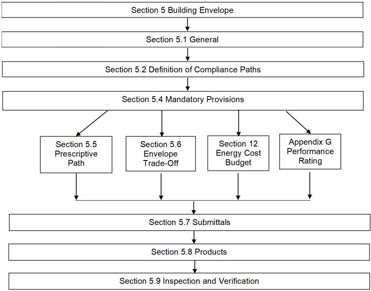
5. BUILDING ENVELOPE
5.1 General
5.1.1 Scope. Section 5 specifies requirements for the building envelope .
5.1.2 New Buildings. Building envelope components installed in new buildings shall comply with the requirements of Section 5.2. 2nd choice: prescriptive or trade-off w/ required for all paths.
5.1.3 Additions to Existing Buildings. Building envelope components installed in additions shall comply with the requirements of Section 5.2.
5.1.4 Alterations to Building Envelopes. Alterations to the building envelope shall comply with the requirements of Section 5.2 for insulation, air leakage, and fenestration applicable to those specific portions of the building that are being altered.
Exceptions to 5.1.4: The following alterations need not comply with these requirements, provided such
alterations will not increase the energy use of the building :
- Installation of storm windows or glazing panels over existing glazing, provided the storm window or glazing panel contains a low-emissivity coating. However, a low-emissivity coating is not required where the existing glazing already has a low-emissivity coating. Installation is permitted to be either on the inside or outside of the existing glazing.
- Replacement of glazing in existing sash and frame, provided the U-factor and SHGC will be equal to or lower than before the glass replacement.
- Alterations to roof, wall, or floor cavities that are insulated to full depth with insulation having a minimum nominal value of R-3.0/in.
- Alterations to walls and floors, where the existing structure is without framing cavities and no new framing cavities are created.
element requirements for roofs in Tables 5.5-0 through 5.5-8 and Section 5.5.3.1.4. 8. Replacement of existing doors that separate a conditioned space from the exterior shall not require the installation of a vestibule or revolving door, provided that an existing vestibule that separates a conditioned space from the exterior shall not be removed.
42 ANSI/ASHRAE/IES Standard 90.1-2022 (I-P)
PDF Page 45
- Replacement of existing fenestration, provided that the area of the replacement fenestration does not exceed 25% of the total fenestration area of an existing building and that the U-factor and
lation requirements in Section 5.5.3.1.1 cannot be met due to existing roof conditions, the roof replacement shall be constructed in accordance with approved construction documents, which shall include
a. a roof inspection report documenting existing roof conditions and b. a roof design minimizing deviation from the requirements of Section 5.5.3.1.1.
Informative Note: The proposed roof design should be prepared by an approved entity capable of determining whether the design complies with the requirements of Section 5.1.4.1 to the extent practical.
5.1.5 Climate. Determine the climate zone for the location. For U.S. locations, follow the procedure in Section 5.1.5.1. For international locations, follow the procedure in Section 5.1.5.2.
Exception to 5.1.5.1: If there are recorded historical climatic data available for a construction site, they
may be used to determine compliance if approved by the building official .
Informative Note: Annex 1 (included at the end of this document) contains an extraction from ASHRAE Standard 169, Table B-1, “U.S. Climate Zones by State and County.”
5.1.5.2 International Locations. For locations in Canada that are listed in ASHRAE Standard 169, Table A-5, “Canada Stations and Climate Zones,” use this table to determine the required assigned climate zone number and, where required, the assigned climate zone letter. For locations in other international countries that are listed in ASHRAE Standard 169, Table A-6, “International Stations and Climate Zones,” use this table to determine the required climate zone number and, where required, the assigned climate zone letter. For all international locations that are not listed either in ASHRAE Standard 169, Table A-5, “Canada Stations and Climate Zones,” or ASHRAE Standard 169, Table A-6, “International Stations and Climate Zones,” use ASHRAE Standard 169, Section A3, “Climate Zone Definitions,” and Table A-3, “Thermal Climate Zone Definitions,” to determine both the climate zone number and letter.
Informative Note: Annex 1 (included at the end of this document) contains extractions from ASHRAE Standard 169, Table A-5, “Canada Stations and Climate Zones”; ASHRAE Standard 169, Table A-6, “International Stations and Climate Zones”; ASHRAE Standard 169, Section A3, “Climate Zone Definitions”; and Table A-3, “Thermal Climate Zone Definitions.”
5.1.6 Space Conditioning Categories 5.1.6.1 Separate building envelope requirements are specified for (a) nonresidential conditioned space, (b) residential conditioned space, and (c) semiheated space .
5.1.6.2 The minimum skylight area requirements in Section 5.5.4.2.3 are also specified for uncondi- tioned spaces .
5.1.6.3 Spaces shall be assumed to be conditioned spaces and shall comply with the requirements for conditioned spaces at the time of construction, regardless of whether mechanical or electrical equipment is included in the building permit application or installed at that time.
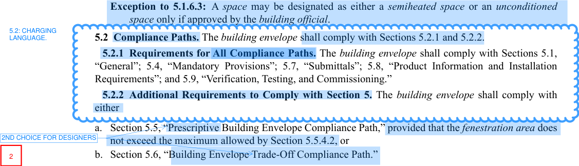
ANSI/ASHRAE/IES Standard 90.1-2022 (I-P) 43
PDF Page 46
5.3 Simplified Building Compliance Path (Not Used)
PRESCRIPTIVE TRADE-OFF
INSTALL AND LABEL PRODUCTS CORRECTLY
SEMIEXTERIOR AIR BARRIER EXCEPTION.
3
5.4 Mandatory Provisions requirements found in Section 5.8.1. 5.4.1 Insulation. Where insulation is required in Section 5.5 or Section 5.6, it shall comply with the INSTALL AND LABEL PRODUCTS CORRECTLY PRESCRIPTIVE TRADE-OFF
5.4.2 Fenestration and Doors. Procedures for determining fenestration and door performance are described in Section 5.8.2. Product samples used for determining fenestration performance shall be production line units or representative of units purchased by the consumer or contractor.
5.4.3 Air Leakage
a. Air leakage control for the building envelope shall comply with this section. Materials and assemblies
that are part of the continuous air barrier and fenestration and doors shall comply with Section 5.8.3.
air barrier of an adjacent conditioned space . 2. Single wythe concrete masonry buildings in Climate Zone 2B.

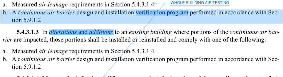
leakage of the building envelope shall not excee d 0.35 cfm/ft [2] under a pressure differential of 75 Pa (0.30 in. of water), with this air leakage rate normalized by the sum of the above- grade and below- grade building envelope areas of the conditioned space and semiheated space and in accordance with this section.
a. Whole- building pressurization testing shall be conducted in accordance with ASTM E3158. For buildings
less than 10,000 ft [2] of gross conditioned floor area, and that contain no more than one single-zone system, air leakage testing may be conducted in accordance with ASTM E779, ASTM E1827, or ASTM E3158. Testing shall be conducted excluding HVAC related elements and be performed by an independent thirdparty verification and testing provider in accordance with Section 4.2.5.1. b. Where a building contains both conditioned space and semiheated space, compliance shall be shown
using one of the following as applicable:
- Separately for the conditioned space and for the semiheated space, with the air leakage rate for the conditioned space normalized by the exterior building envelope area of the conditioned space and the air leakage rate for the semiheated space normalized by the semiexterior building envelope area of the semiheated space
- For the conditioned space and for the semiheated space together, with the air leakage rate for the overall space normalized by the sum of the exterior building envelope area and the semiexterior building envelope area minus the semiexterior building envelope area that separates the conditioned space from the semiheated space c. Where the measured air leakage rate exceeds 0.35 cfm/ft [2] but does not exceed 0.45 cfm/ft [2], a diagnostic
evaluation, such as a smoke tracer or infrared imaging, shall be conducted while the building is pressurized, and any leaks noted shall be sealed if such sealing can be made without destruction of existing building components. In addition, a visual inspection of the air barrier shall be conducted, and any leaks noted shall be sealed if such sealing can be made without destruction of existing building components.
44 ANSI/ASHRAE/IES Standard 90.1-2022 (I-P)
PDF Page 47
An additional report identifying the corrective actions taken to seal leaks shall be submitted to the code official and the building owner and shall be deemed to satisfy the requirements of this section. d. Where the measured air leakage rate exceeds 0.45 cfm/ft [2], corrective actions must be made to the enve-
lope and an additional test completed where results are 0.45 cfm/ft [2] or less in order to demonstrate compliance. e. Reporting shall be in compliance with Section 4.2.5.1.2.
5.4.3.2 Continuous Air Barrier Design and Installation. The continuous air barrier shall be designed and installed in the following manner:
c. The continuous air barrier shall extend over all surfaces of the building envelope and be identified in the
construction documents to be continuous across the components of the below- grade areas, walls, fenes- tration, doors, and roofs . d. The continuous air barrier shall be designed to resist positive and negative pressures from wind, stack
effect, and mechanical ventilation and allow for anticipated movements. e. The following areas of the continuous air barrier in the building envelope shall be wrapped, sealed,
caulked, gasketed, or taped in an approved manner to minimize air leakage :
- Joints around fenestration and door frames
- Junctions between walls and floors ; between walls at building corners; between walls and roofs, including parapets and copings; and walls at foundations
- Penetrations through the continuous air barrier in building envelope roofs, walls, and floors
- Building assemblies used as ducts or plenums
- Joints, seams, connections between planes, and other changes in continuous air barrier materials
- Building and service components projecting through or attached through the continuous air barrier
- Junctions of the continuous air barrier that separate conditioned spaces from unconditioned spaces, semiheated spaces, and areas that are not enclosed spaces 5.4.3.3 Loading Dock Weatherseals. In Climate Zones 0 and 4 through 8, cargo doors and loading dock doors shall be equipped with weatherseals to restrict air leakage when vehicles are parked in the doorway.
5.4.3.4 Vestibules and Revolving Doors. Vestibules and revolving doors shall be installed in accordance with this section.
5.4.3.4.1 Location. Building entrances that separate conditioned space from the exterior shall have one of the following:
a. An enclosed vestibule, with all doors opening into and out of the vestibule equipped with self-closing
devices b. A revolving door or doors opening into a vestibule or directly into the conditioned space c. A combination of (a) and (b)
5.4.3.4.2 Vestibule Size. Vestibules shall be designed so that in passing through the vestibule it is not necessary for the interior and exterior doors to open at the same time. Interior and exterior doors shall have a minimum distance between them of not less than 7 ft when in the closed position. The floor area of each vestibule shall not exceed the greater of 50 ft [2] or 2% of the gross conditioned floor area for that level of the building .
5.4.3.4.3 Vestibule Envelope. The exterior surfaces of both conditioned vestibules and unconditioned vestibules shall comply with the continuous air barrier requirements.
VESTIBULE EXCEPTIONS
- Doors opening directly from a dwelling unit.
- Building entrances in buildings located in Climate Zone 1 or 2.
- Doors opening into semiheated spaces .
- Enclosed elevator lobbies for building entrances directly from parking garages.
- Building entrances in buildings that are located in Climate Zone 3, where the building is less than four stories above grade and less than 10,000 ft [2] in gross conditioned floor area.
- Building entrances in buildings that are located in Climate Zone 0, 4, 5, 6, 7, or 8, where the building is less than 1000 ft [2] in gross conditioned floor area.
ANSI/ASHRAE/IES Standard 90.1-2022 (I-P) 45
PDF Page 48
CHARGING LANGUAGE FOR PRESCRIPTIVE
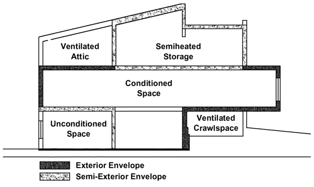
Figure 5.5.2 Exterior and semiexterior building envelope.
- Doors that open directly from a space that is less than 3000 ft [2 ] in area and is separate from the building entrance.
- Self-closing doors in buildings in Climate Zones 0, 3, and 4 that have an air curtain unit complying with Sections 6.4.3.9 and 10.4.5.
- Self-closing doors in buildings 15 stories or less in Climate Zones 5 through 8 that have an air curtain unit complying with Sections 6.4.3.9 and 10.4.5.
climate.
The exterior surfaces of conditioned vestibules shall comply with the building envelope requirements for a conditioned space .
5.5.2 Semiexterior Building Envelope. If a building contains any semiheated space or unconditioned space then the semiexterior building envelope shall comply with the requirements for semiheated space in Tables 5.5-0 through 5.5-8 for the appropriate climate. (See Figure 5.5.2.)
The interior surfaces and exterior surfaces of unconditioned vestibules shall comply with the building envelope requirements for a semiheated space .
5.5.3 Opaque Elements. For all opaque elements, compliance with Tables 5.5-0 through 5.5-8 for each class of construction as described in Normative Appendix A, Sections A2 through A8 shall be demonstrated by one of the following two methods:
a. Providing a minimum rated R-value of insulation added to the assembly equal to or greater than the insu lation minimum R-value required of each insulation component. b. Providing insulation such that the maximum U-factor, C-factor, or F-factor for the entire assembly is not
exceeded as determined by one of the following:
-
Precalculated values in accordance with Normative Appendix A, Section A1.1.
-
Applicant-determined values in accordance with Normative Appendix A, Section A1.2 where such values are approved by the code official . Exceptions to 5.5.3:
-
For opaque assemblies not complying with the classes of construction as described in Normative Appendix A, Sections A2 through A8, compliance with the maximum U-factors for the “attic and other” or “wood frame and other” opaque element conditions in Tables 5.5-0 through 5.5-8 shall be

46 ANSI/ASHRAE/IES Standard 90.1-2022 (I-P)
PDF Page 49
Table 5.5.3.1.4 Increased Roof Insulation Levels
Roofs Nonresidential Residential
Opaque Elements
Assembly Maximum
Insulation Min. R-Value
Climate Zone 0
Assembly Maximum
Insulation Min. R-Value
Insulation entirely above deck U-0.027 R-36 c.i. U-0.027 R-36 c.i.
Metal buildings U-0.028 R-35
Climate Zones 1 to 3
Insulation entirely above deck U-0.030 R-33 c.i. U-0.029 R-34 c.i.
Metal buildings U-0.028 R-35
demonstrated by testing or calculations representative of the designed assembly in accordance with Normative Appendix A, Section A9.1 where approved by the code official . 2. For multiple assemblies within a single class of construction for a single space conditioning cate- gory, compliance shall be shown for either (a) the most restrictive requirement or (b) an areaweighted average U-factor, C-factor, or F-factor .
5.5.3.1 Roofs 5.5.3.1.1 All roofs shall comply with the insulation values specified in Tables 5.5-0 through 5.5-8. 5.5.3.1.2 Roof Curbs. Skylight and other roof curbs shall be insulated to not less than R-5.0. 5.5.3.1.3 Joints in Roof Insulation. Joints in the insulation shall be installed in accordance with Section 5.8.1.10.
5.5.3.1.4 Roof Solar Reflectance and Thermal Emittance. Roofs in Climat e Zones 0 through 3 s hall have one of the following:
a. A minimum three-year-aged solar reflectance of 0.55 and a minimum three-year-aged thermal emittance
of 0.75 when tested in accordance with CRRC S100. b. A minimum Solar Reflectance Index of 64 when determined in accordance with the Solar Reflectance
Index method in ASTM E1980 using a convection coefficient of 2.1 Btu/h·ft [2] ·°F, based on three-yearaged solar reflectance and three-year-aged thermal emittance tested in accordance with CRRC S100. c. Increased roof insulation levels found in Table 5.5.3.1.4.
The values for three-year-aged solar reflectance and three-year-aged thermal emittance shall be determined by a laboratory accredited by a nationally recognized accreditation organization and shall be labeled and certified by the manufacturer .
Exceptions to 5.5.3.1.4:
- Ballasted roofs with a minimum stone ballast of 17 lb/ft [2 ] or 23 lb/ft [2] pavers.
- Vegetative roof systems that contain a minimum thickness of 2.5 in. of growing medium and covering a minimum of 75% of the roof area with durable plantings.
- Roofs where a minimum of 75% of the roof area a. is shaded during the peak sun angle on June 21 by permanent components or features of the
building ; b. is covered by offset photovoltaic arrays, building -integrated photovoltaic arrays, or solar air
or water collectors; or c. is permitted to be interpolated using a combination of 1 and 2 above. 4. Steep-sloped roofs . 5. Low-sloped metal building roofs in Climate Zones 2 and 3. 6. Roofs over ventilated attics, roofs over semiheated spaces, or roofs over conditioned spaces that are not cooled spaces . 7. Asphaltic membranes in Climate Zones 2 and 3.
5.5.3.1.5 Insulated Metal Panels. The U-factor of roof assemblies that include insulated metal panels shall not be greater than the U-factors of Tables 5.5-0 through 5.5-8 for the applicable class of construction . U-factors of insulated metal panels shall be determined in accordance with Section A9.4.7.
ANSI/ASHRAE/IES Standard 90.1-2022 (I-P) 47
PDF Page 50
Table 5.5-0 Building Envelope Requirements for Climate Zone 0 (A,B)*
Nonresidential Residential Semiheated
Insulation Min. R-Value
Assembly Maximum
Roofs
Insulation Min. R-Value
Assembly Maximum
Insulation Min. R-Value
Opaque Elements
Insulation entirely
above deck
Assembly Maximum
U-0.039 R-25 c.i. U-0.032 R-30 c.i. U-0.218 R-3.8 c.i.
Metal building [ a] U-0.041 R-10 + R-19 FC U-0.041 R-10 + R-19 FC U-0.115 R-10
Attic and other U-0.027 R-38 U-0.027 R-38 U-0.081 R-13
Walls, above-Grade
Mass U-0.580 NR U-0.151 [b] R-5.7 c.i. [b] U-0.580 NR
Metal building U-0.094 R-0 + R-9.8 c.i. U-0.094 R-0 + R-9.8 c.i. U-0.352 NR
Steel-framed U-0.124 R-13 U-0.124 R-13 U-0.352 NR
Wood-framed and other U-0.089 R-13 U-0.089 R-13 U-0.292 NR
Wall, below-Grade
Below-grade wall C-1.140 NR C-1.140 NR C-1.140 NR
Floors
Mass U-0.322 NR U-0.322 NR U-0.322 NR
Steel joist U-0.350 NR U-0.350 NR U-0.350 NR
Wood-framed and other U-0.282 NR U-0.282 NR U-0.282 NR
Slab-on-Grade Floors
Unheated F-0.730 NR F-0.730 NR F-0.730 NR
Heated F-1.020 R-7.5 for 12 in. F-1.020 R-7.5 for 12 in. F-1.020 R-7.5 for 12 in.
Opaque Doors
Swinging U-0.370 U-0.370 U-0.700
Nonswinging U-0.310 U-0.310 U-1.450
Assembly
Max. U
Assembly
Max. U
Assembly Max. SHGC
Assembly
Min. VT/SHGC
Assembly Max. SHGC
Assembly
Min. VT/SHGC
Assembly Max. SHGC
Assembly
Min. VT/SHGC
Fenestration
Assembly
Max. U
Vertical Fenestration, 0% to 40% of Wall
Fixed 0.50 0.22 1.10 (for all
0.50 0.22 1.10 (for all
types)
1.20 NR (for all
types)
NR (for all
Operable 0.62 0.20 types) 0.62 0.20 types) 1.20 types) types)
types)
Entrance door 0.83 0.20 0.83 0.20 1.10
Skylight, 0% to 3% of Roof
All types 0.70 0.30 NR 0.70 0.30 NR 1.80 NR NR
- The following definitions apply: c.i. = continuous insulation (see Section 3.2), FC = filled cavity (see Section A2.3.2.5), NR = no (insulation) requirement. a. When using the R-value compliance method for metal building roofs, a thermal spacer block is required (see Section A2.3.2). b. Exception to Section 5.5.3.2 applies for mass walls above grade .
48 ANSI/ASHRAE/IES Standard 90.1-2022 (I-P)
PDF Page 51
Table 5.5-1 Building Envelope Requirements for Climate Zone 1 (A,B)*
Nonresidential Residential Semiheated
Insulation Min. R-Value
Assembly Maximum
Roofs
Insulation Min. R-Value
Assembly Maximum
Insulation Min. R-Value
Opaque Elements
Insulation entirely
above deck
Assembly Maximum
U-0.048 R-20 c.i. U-0.039 R-25 c.i. U-0.218 R-3.8 c.i.
Metal building [ a] U-0.041 R-10 + R-19 FC U-0.041 R-10 + R-19 FC U-0.115 R-10
Attic and other U-0.027 R-38 U-0.027 R-38 U-0.081 R-13
Walls, above Grade
Mass U-0.580 NR U-0.151 [b] R-5.7 c.i. [b] U-0.580 NR
Metal building U-0.094 R-0 + R-9.8 c.i. U-0.094 R-0 + R-9.8 c.i. U-0.352 NR
Steel-framed U-0.124 R-13 U-0.124 R-13 U-0.352 NR
Wood-framed and other U-0.089 R-13 U-0.089 R-13 U-0.292 NR
Wall, below Grade
Below-grade wall C-1.140 NR C-1.140 NR C-1.140 NR
Floors
Mass U-0.322 NR U-0.322 NR U-0.322 NR
Steel joist U-0.350 NR U-0.350 NR U-0.350 NR
Wood-framed and other U-0.282 NR U-0.282 NR U-0.282 NR
Slab-on-Grade Floors
Unheated F-0.730 NR F-0.730 NR F-0.730 NR
Heated F-1.020 R-7.5 for 12 in. F-1.020 R-7.5 for 12 in. F-1.020 R-7.5 for 12 in.
Opaque Doors
Swinging U-0.370 U-0.370 U-0.700
Nonswinging U-0.310 U-0.310 U-1.450
Assembly
Max. U
Assembly
Max. U
Assembly Max. SHGC
Assembly
Min. VT/SHGC
Assembly Max. SHGC
Assembly
Min. VT/SHGC
Assembly Max. SHGC
Assembly
Min. VT/SHGC
Fenestration
Assembly
Max. U
Vertical Fenestration, 0% to 40% of Wall
Fixed 0.50 0.23 1.10 (for all
0.50 0.23 1.10 (for all
types)
1.20 NR (for all types)
NR (for all
Operable 0.62 0.21 types) 0.62 0.21 types) 1.20 types)
types)
Entrance door 0.83 0.21 0.83 0.21 1.10
Skylight, 0% to 3% of Roof
All types 0.70 0.30 NR 0.70 0.30 NR 1.80 NR NR
- The following definitions apply: c.i. = continuous insulation (see Section 3.2), FC = filled cavity (see Section A2.3.2.5), NR = no (insulation) requirement. a. When using the R-value compliance method for metal building roofs, a thermal spacer block is required (see Section A2.3.2). b. Exception to Section 5.5.3.2 applies for mass walls above grade .
ANSI/ASHRAE/IES Standard 90.1-2022 (I-P) 49
PDF Page 52
Table 5.5-2 Building Envelope Requirements for Climate Zone 2 (A,B)*
Nonresidential Residential Semiheated
Insulation Min. R-Value
Assembly Maximum
Roofs
Insulation Min. R-Value
Assembly Maximum
Insulation Min. R-Value
Opaque Elements
Insulation entirely
above deck
Assembly Maximum
U-0.039 R-25 c.i. U-0.039 R-25 c.i. U-0.173 R-5 c.i.
Metal building [ a] U-0.041 R-10 + R-19 FC U-0.041 R-10 + R-19 FC U-0.096 R-16
Attic and other U-0.027 R-38 U-0.027 R-38 U-0.053 R-19
Walls, above Grade
Mass U-0.151 [b] R-5.7 c.i. [b] U-0.123 R-7.6 c.i. U-0.580 NR
Metal building U-0.094 R-0 + R-9.8 c.i. U-0.094 R-0 + R-9.8. c.i. U-0.162 R-13
Steel-framed U-0.084 R-13 + R-3.8 c.i. U-0.064 R-13 + R-7.5 c.i. U-0.124 R-13
Wood-framed and other U-0.089 R-13 U-0.089 R-13 U-0.089 R-13
Wall, below Grade
Below-grade wall C-1.140 NR C-1.140 NR C-1.140 NR
Floors
Mass U-0.107 R-6.3 c.i. U-0.087 R-8.3 c.i. U-0.322 NR
Steel joist U-0.038 R-30 U-0.038 R-30 U-0.069 R-13
Wood-framed and other U-0.033 R-30 U-0.033 R-30 U-0.066 R-13
Slab-on-Grade Floors
Unheated F-0.730 NR F-0.730 NR F-0.730 NR
Heated F-0.900 R-10 for 24 in. F-0.860 R-15 for 24 in. F-1.020 R-7.5 for 12 in.
Opaque Doors
Swinging U-0.370 U-0.370 U-0.700
Nonswinging U-0.310 U-0.310 U-1.450
Assembly
Max. U
Assembly
Max. U
Assembly
Min. VT/SHGC
Assembly Max. SHGC
Assembly
Min. VT/SHGC
Assembly Max. SHGC
Assembly
Min. VT/SHGC
Assembly
Max. SHGC
Fenestration
Assembly
Max. U
Vertical Fenestration, 0% to 40% of Wall
Fixed 0.45 0.25 1.10 (for all
0.45 0.25 1.10 (for all
types)
0.50 NR (for all
types)
NR (for all
Operable 0.60 0.23 types) 0.60 0.23 types) 0.65 types) types)
types)
Entrance door 0.77 0.23 0.77 0.23 0.77
Skylight, 0% to 3% of Roof
All types 0.65 0.30 NR 0.65 0.30 NR 0.90 NR NR
- The following definitions apply: c.i. = continuous insulation (see Section 3.2), FC = filled cavity (see Section A2.3.2.5), NR = no (insulation) requirement. a. When using the R-value compliance method for metal building roofs, a thermal spacer block is required (see Section A2.3.2). b. Exception to Section 5.5.3.2 applies for mass walls above grade .
50 ANSI/ASHRAE/IES Standard 90.1-2022 (I-P)
PDF Page 53
Table 5.5-3 Building Envelope Requirements for Climate Zone 3 (A,B,C)*
Nonresidential Residential Semiheated
Insulation Min. R-Value
Assembly Maximum
Roofs
Insulation Min. R-Value
Assembly Maximum
Insulation Min. R-Value
Opaque Elements
Insulation entirely
above deck
Assembly Maximum
U-0.039 R-25 c.i. U-0.039 R-25 c.i. U-0.119 R-7.6 c.i.
Metal building [ a] U-0.041 R-10 + R-19 FC U-0.041 R-10 + R-19 FC U-0.096 R-16
Attic and other U-0.027 R-38 U-0.027 R-38 U-0.053 R-19
Walls, above Grade
Mass U-0.123 R-7.6 c.i. U-0.104 R-9.5 c.i. U-0.580 NR
Metal building U-0.094 R-0 + R-9.8 c.i. U-0.072 R-0 + R-13 c.i. U-0.162 R-13
Steel-framed U-0.077 R-13 + R-5 c.i. U-0.064 R-13 + R-7.5 c.i. U-0.124 R-13
Wood-framed and other U-0.089 R-13 U-0.064 R-13 + R-3.8 c.i. or R-20 U-0.089 R-13
Wall, below Grade
Below-grade wall C-1.140 NR C-1.140 NR C-1.140 NR
Floors
Mass U-0.074 R-10 c.i. U-0.074 R-10 c.i. U-0.137 R-4.2 c.i.
Steel joist U-0.038 R-30 U-0.038 R-30 U-0.052 R-19
Wood-framed and other U-0.033 R-30 U-0.033 R-30 U-0.051 R-19
Slab-on-Grade Floors
Unheated F-0.730 NR F-0.540 R-10 for 24 in. F-0.730 NR
Heated F-0.860 R-15 for 24 in. F-0.860 R-15 for 24 in. F-1.020 R-7.5 for 12 in.
Opaque Doors
Swinging U-0.370 U-0.370 U-0.370
Nonswinging U-0.310 U-0.310 U-0.360
Assembly
Max. U
Assembly
Max. U
Assembly
Min. VT/SHGC
Assembly Max. SHGC
Assembly
Min. VT/SHGC
Assembly Max. SHGC
Assembly
Min. VT/SHGC
Assembly
Max. SHGC
Fenestration
Assembly
Max. U
Vertical Fenestration, 0% to 40% of Wall
Fixed 0.42 0.25 1.10 (for all
0.42 0.25 1.10 (for all
types)
0.50 NR (for all
types)
NR (for all
Operable 0.54 0.23 types) 0.54 0.23 types) 0.65 types) types)
types)
Entrance door 0.68 0.23 0.68 0.23 0.77
Skylight, 0% to 3% of Roof
All types 0.55 0.30 NR 0.55 0.30 NR 0.90 NR NR
- The following definitions apply: c.i. = continuous insulation (see Section 3.2), FC = filled cavity (see Section A2.3.2.5), NR = no (insulation) requirement. a. When using the R-value compliance method for metal building roofs, a thermal spacer block is required (see Section A2.3.2).
ANSI/ASHRAE/IES Standard 90.1-2022 (I-P) 51
PDF Page 54
| Nonresidential | Residential | Semiheated |
|---|---|---|
| ** Opaque Elements** Assembly Maximum Insulation Min. R-Value | ||
| ** Opaque Elements** Assembly Maximum Insulation Min. R-Value | Assembly Maximum Insulation Min. R-Value | Assembly Maximum Insulation Min. R-Value |
| Insulation entirely above deck U-0.032 R-30_c.i._ Metal building a U-0.037 R-19 + R-11_Ls_ or R-25 + R-8_Ls_ Attic and other U-0.021 R-49 | Roofs U-0.032 R-30_c.i._ U-0.037 R-19 + R-11_Ls_ or R-25 + R-8_Ls_ U-0.021 R-49 | U-0.093 R-10_c.i._ U-0.082 R-19 U-0.034 R-30 |
| Wa Mass U-0.104 R-9.5_c.i._ Metal building U-0.060 R-0 + R-15.8_c.i._ Steel-framed U-0.064 R-13 + R-7.5_c.i._ Wood-framed and other U-0.064 R-13 + R-3.8_c.i._ or R-20 | lls, above Grade U-0.090 R-11.4_c.i._ U-0.050 R-0 + R-19_c.i._ U-0.064 R-13 + R-7.5 c.i U-0.064 R-13 + R-3.8_c.i._ or R-20 | U-0.580 NR U-0.162 R-13 U-0.124 R-13 U-0.089 R-13 |
| Wa Below-grade wall C-0.119 R-7.5_c.i._ | ll, below Grade C-0.092 R-10_c.i._ | C-1.140 NR |
| Mass U-0.057 R-14.6_c.i._ Steel joist U-0.038 R-30 Wood-framed and other U-0.033 R-30 | Floors U-0.051 R-16.7_c.i._ U-0.038 R-30 U-0.033 R-30 | U-0.107 R-6.3_c.i._ U-0.052 R-19 U-0.051 R-19 |
| Slab Unheated F-0.520 R-15 for 24 in. Heated F-0.843 R-20 for 24 in. | -on-Grade Floors F-0.520 R-15 for 24 in. F-0.688 R-20 for 48 in. | F-0.730 NR F-0.900 R-10 for 24 in. |
Swinging U-0.370 Nonswinging U-0.310 | Opaque Doors U-0.370 U-0.310 | U-0.370 U-0.360 |
| Fenestration Assembly Max. U Assembly Max. SHGC Assembly Min. VT/SHGC Nonresidential | Assembly Max. U Assembly Max. SHGC Assembly Min. VT/SHGC Residential | Assembly Max. U Assembly Max. SHGC Assembly Min. VT/SHGC Semiheated |
| Vertical Fene Fixed 0.36 0.36 1.10 (for all types) Operable 0.45 0.33 Entrance door 0.63 0.33 | _ stration_, 0% to 40% of_Wall_ 0.36 0.36 1.10 (for all types) 0.45 0.33 0.63 0.33 | 0.50 NR (for all types) NR (for all types) 0.65 0.77 |
| Skyligh All types 0.50 0.40 NR | t, 0% to 3% of_Roof_ 0.50 0.40 NR | 0.75 NR NR |
- The following definitions apply: c.i. = continuous insulation (see Section 3.2), FC = filled cavity (see Section A2.3.2.5), Ls = liner system (see Section A2.3.2.4); NR = no (insulation) requirement. a. When using the R-value compliance method for metal building roofs, a thermal spacer block is required (see Section A2.3.2).
52 ANSI/ASHRAE/IES Standard 90.1-2022 (I-P)
PDF Page 55
Table 5.5-5 Building Envelope Requirements for Climate Zone 5 (A,B,C)*
Nonresidential Residential Semiheated
Insulation Min. R-Value
Assembly Maximum
Roofs
Insulation Min. R-Value
Assembly Maximum
Insulation Min. R-Value
Opaque Elements
Insulation entirely
above deck
Assembly Maximum
U-0.032 R-30 c.i. U-0.032 R-30 c.i. U-0.063 R-15 c.i.
Metal building [ a] U-0.037 R-19 + R-11 Ls or
R-25 + R-8 Ls
U-0.037 R-19 + R-11 Ls or
R-25 + R-8 Ls
U-0.082 R-19
Attic and other U-0.021 R-49 U-0.021 R-49 U-0.034 R-30
Walls, above grade
Mass U-0.090 R-11.4 c.i. U-0.080 R-13.3 c.i. U-0.151 [b] R-5.7 c.i. [b]
Metal building U-0.050 R-0 + R-19 c.i. U-0.050 R-0 + R-19 c.i. U-0.094 R-0 + R-9.8 c.i.
Steel-framed U-0.055 R-13 + R-10 c.i. U-0.055 R-13 + R-10 c.i. U-0.084 R-13+R-3.8 c.i.
Wood-framed and other U-0.051 R-13 + R-7.5 c.i. or
R-19 + R-5 c.i.
U-0.051 R-13 + R-7.5 c.i. or
R-19 + R-5 c.i.
U-0.089 R-13
Wall, below Grade
Below-grade wall C-0.119 R-7.5 c.i. C-0.092 R-10 c.i. C-1.140 NR
Floors
Mass U-0.057 R-14.6 c.i. U-0.051 R-16.7 c.i. U-0.107 R-6.3 c.i.
Steel joist U-0.038 R-30 U-0.038 R-30 U-0.052 R-19
Wood-framed and other U-0.033 R-30 U-0.033 R-30 U-0.051 R-19
Slab-on-Grade Floors
Unheated F-0.520 R-15 for 24 in F-0.510 R-20 for 24 in. F-0.730 NR
Heated F-0.688 R-20 for 48 in. F-0.688 R-20 for 48 in. F-0.900 R-10 for 24 in.
Opaque Doors
Swinging U-0.370 U-0.370 U-0.370
Nonswinging U-0.310 U-0.310 U-0.360
Assembly
Max. U
Assembly
Max. U
Assembly
Min. VT/SHGC
Assembly Max. SHGC
Assembly
Min. VT/SHGC
Assembly Max. SHGC
Assembly
Min. VT/SHGC
Assembly
Max. SHGC
Fenestration
Assembly
Max. U
Vertical Fenestration, 0% to 40% of Wall
Fixed 0.36 0.38 1.10 (for all
0.36 0.38 1.10 (for all
types)
0.50 NR (for all
types)
NR (for all
Operable 0.45 0.33 types) 0.45 0.33 types) 0.65 types) types)
types)
Entrance door 0.63 0.33 0.63 0.33 0.77
Skylight, 0% to 3% of Roof
All types 0.50 0.40 NR 0.50 0.40 NR 0.75 NR NR
- The following definitions apply: c.i. = continuous insulation (see Section 3.2), FC = filled cavity (see Section A2.3.2.5), Ls = liner system (see Section A2.3.2.4); NR = no (insulation) requirement. a. When using the R-value compliance method for metal building roofs, a thermal spacer block is required (see Section A2.3.2). b. Exception to Section 5.5.3.2 applies for mass walls above grade .
ANSI/ASHRAE/IES Standard 90.1-2022 (I-P) 53
PDF Page 56
Table 5.5-6 Building Envelope Requirements for Climate Zone 6 (A,B)*
Nonresidential Residential Semiheated
Insulation Min. R-Value
Assembly Maximum
Roofs
Insulation Min. R-Value
Assembly Maximum
Insulation Min. R-Value
Opaque Elements
Insulation entirely
above deck
Assembly Maximum
U-0.032 R-30 c.i. U-0.032 R-30 c.i. U-0.063 R-15 c.i.
Metal building [ a] U-0.031 R-25 + R-11 Ls U-0.029 R-30 + R-11 Ls U-0.060 R-19 + R-19
Attic and other U-0.021 R-49 U-0.021 R-49 U-0.034 R-30
Walls, above Grade
Mass U-0.080 R-13.3 c.i. U-0.071 R-15.2 c.i. U-0.151 [b] R-5.7 c.i. [b]
Metal building U-0.050 R-0 + R-19 c.i. U-0.050 R-0 + R-19 c.i. U-0.094 R-0 + R-9.8 c.i.
Steel-framed U-0.049 R-13 + R-12.5 c.i. U-0.049 R-13 + R-12.5 c.i. U-0.084 R-13 + R-3.8 c.i.
Wood-framed and other U-0.051 R-13 + R-7.5 c.i. or
R-19 + R-5 c.i.
U-0.051 R-13 + R-7.5 c.i. or
R-19 + R-5 c.i.
U-0.089 R-13
Wall, below Grade
Below-grade wall C-0.092 R-10 c.i. C-0.063 R-15 c.i. C-0.119 R-7.5 c.i
Floors
Mass U-0.051 R-16.7 c.i. U-0.051 R-16.7 c.i. U-0.087 R-8.3 c.i.
Steel joist U-0.032 R-38 U-0.032 R-38 U-0.052 R-19
Wood-framed and other U-0.027 R-38 U-0.027 R-38 U-0.051 R-19
Slab-on-Grade Floors
Unheated F-0.510 R-20 for 24 in. F-0.434 R-20 for 48 in F-0.730 NR
Heated F-0.688 R-20 for 48 in. F-0.671 R-25 for 48 in. F-0.860 R-15 for 24 in.
Opaque Doors
Swinging U-0.370 U-0.370 U-0.370
Nonswinging U-0.310 U-0.310 U-0.360
Assembly
Max. U
Assembly
Max. U
Assembly
Min. VT/SHGC
Assembly Max. SHGC
Assembly
Min. VT/SHGC
Assembly Max. SHGC
Assembly
Min. VT/SHGC
Assembly
Max. SHGC
Fenestration
Assembly
Max. U
Vertical Fenestration, 0% to 40% of Wall
Fixed 0.34 0.38 1.10 (for all
0.34 0.38 1.10 (for all
types)
0.39 NR (for all
types)
NR (for all
Operable 0.42 0.34 types) 0.42 0.34 types) 0.48 types) types)
types)
Entrance door 0.63 0.34 0.63 0.34 0.68
Skylight, 0% to 3% of Roof
All types 0.47 0.40 NR 0.50 0.40 NR 0.75 NR NR
- The following definitions apply: c.i. = continuous insulation (see Section 3.2), FC = filled cavity (see Section A2.3.2.5), Ls = liner system (see Section A2.3.2.4); NR = no (insulation) requirement. a. When using the R-value compliance method for metal building roofs, a thermal spacer block is required (see Section A2.3.2). b. Exception to Section 5.5.3.2 applies for mass walls above grade .
54 ANSI/ASHRAE/IES Standard 90.1-2022 (I-P)
PDF Page 57
Table 5.5-7 Building Envelope Requirements for Climate Zone 7*
Nonresidential Residential Semiheated
Insulation Min. R-Value
Assembly Maximum
Roofs
Insulation Min. R-Value
Assembly Maximum
Insulation Min. R-Value
Opaque Elements
Insulation entirely
above deck
Assembly Maximum
U-0.028 R-35 c.i. U-0.028 R-35 c.i. U-0.039 R-25 c.i.
Metal building [ a] U-0.029 R-30 + R-11 Ls U-0.029 R-30 + R-11 Ls U-0.037 R-19 + R-11 Ls or
R-25 + R-8 Ls
Attic and other U-0.017 R-60 U-0.017 R-60 U-0.027 R-38
Walls, above Grade
Mass U-0.071 R-15.2 c.i. U-0.071 R-15.2 c.i. U-0.123 R-7.6 c.i.
Metal building U-0.044 R-0 + R.22.1 c.i. U-.044 R-0 + R.22.1 c.i. U-0.072 R-0 + R-13 c.i.
Steel-framed U-0.049 R-13 + R-12.5 c.i. U-0.042 R-13 + R-15.6 c.i. U-0.064 R-13 + R-7.5 c.i.
Wood-framed and other U-0.051 R-13 + R-7.5 c.i. or
R-19 + R-5 c.i.
U-0.051 R-13 + R-7.5 c.i. or
R-19 + R-5 c.i.
U-0.064 R-13 + R-3.8 c.i.
Wall, below Grade
Below-grade wall C-0.063 R-15 c.i. C-0.063 R-15 c.i. C-0.119 R-7.5 c.i.
Floors
Mass U-0.042 R-20.9 c.i. U-0.042 R-20.9 c.i. U-0.074 R-10.4 c.i.
Steel joist U-0.032 R-38 U-0.032 R-38 U-0.052 R-19
Wood-framed and other U-0.027 R-38 U-0.027 R-38 U-0.051 R-19
Slab-on-Grade Floors
Unheated F-0.510 R-20 for 24 in. F-0.434 R-20 for 48 in. F-0.730 NR
Heated F-0.671 R-25 for 48 in. F-0.671 R-25 for 48 in. F-0.860 R-15 for 24 in.
Opaque Doors
Swinging U-0.370 U-0.370 U-0.370
Nonswinging U-0.310 U-0.310 U-0.310
Assembly
Max. U
Assembly
Max. U
Assembly Max. SHGC
Assembly
Min. VT/SHGC
Assembly Max. SHGC
Assembly
Min. VT/SHGC
Assembly Max. SHGC
Assembly
Min. VT/SHGC
Fenestration
Assembly
Max. U
Vertical Fenestration, 0% to 40% of Wall
Fixed 0.29 0.40 1.10 (for all
0.29 0.40 1.10 (for all
types)
0.36 NR (for all
types)
NR (for all
Operable 0.36 0.36 types) 0.36 0.36 types) 0.44 types) types)
types)
Entrance door 0.63 0.36 0.63 0.36 0.63
Skylight, 0% to 3% of Roof
All types 0.44 NR NR 0.44 NR NR 0.75 NR NR
- The following definitions apply: c.i. = continuous insulation (see Section 3.2), FC = filled cavity (see Section A2.3.2.5), Ls = liner system (see Section A2.3.2.4); NR = no (insulation) requirement. a. When using the R-value compliance method for metal building roofs, a thermal spacer block is required (see Section A2.3.2).
ANSI/ASHRAE/IES Standard 90.1-2022 (I-P) 55
PDF Page 58
Table 5.5-8 Building Envelope Requirements for Climate Zone 8*
Nonresidential Residential Semiheated
Insulation Min. R-Value
Assembly Maximum
Insulation Min. R-Value
Assembly Maximum
Insulation Min. R-Value
Opaque Elements
Roofs
Insulation entirely
above deck
Assembly Maximum
U-0.028 R-35 c.i. U-0.028 R-35 c.i. U-0.039 R-25 c.i.
Metal building [ a] U-0.026 R-25 + R-11+R-11 Ls U-0.026 R-25 + R-11+R-11 Ls U-0.037 R-19+R-11 Ls or
R-25 + R-8 Ls
Attic and other U-0.017 R-60 U-0.017 R-60 U-0.027 R-38
Walls, above Grade
Mass U-0.048 R-19 c.i. U-0.048 R-19 c.i. U-0.104 R-9.5 c.i.
Metal building U-0.039 R-0 + R-25 c.i. U-0.039 R-0 + R-25 c.i. U-0.060 R-0 + R-15.8 c.i.
Steel-framed U-0.037 R-13 + R-18.8 c.i. U-0.037 R-13 + R-18.8 c.i. U-0.064 R-13 + R-7.5 c.i.
Wood-framed and other U-0.032 R-13 + R-18.8 c.i. U-0.032 R-13 + R-18.8 c.i. U-0.051 R-13 + R-7.5 c.i.
Wall, below Grade
Below-grade wall C-0.063 R-15 c.i. C-0.063 R-15 c.i. C-0.119 R-7.5 c.i.
Floors
Mass U-0.038 R-23 c.i. U-0.038 R-23 c.i. U-0.064 R-12.5 c.i.
Steel joist U-0.032 R-38 U-0.032 R-38 U-0.052 R-19
Wood-framed and other U-0.027 R-38 U-0.027 R-38 U-0.033 R-30
Slab-on-Grade Floors
Unheated F-0.434 R-20 for 48 in. F-0.424 R-25 for 48 in. F-0.540 R-10 for 24 in.
Heated F-0.671 R-25 for 48 in. F-0.373 R-20 full slab F-0.860 R-15 for 24 in.
Opaque Doors
Swinging U-0.370 U-0.370 U-0.370
Nonswinging U-0.310 U-0.310 U-0.310
Assembly
Max. U
Assembly
Max. U
Assembly
Min. VT/SHGC
Assembly Max. SHGC
Assembly
Min. VT/SHGC
Assembly Max. SHGC
Assembly
Min. VT/SHGC
Assembly
Max. SHGC
Fenestration
Assembly
Max. U
Vertical Fenestration, 0% to 40% of Wall
Fixed 0.26 0.40 1.10 (for all
0.26 0.40 1.10 (for all
types)
0.36 NR (for all
types)
NR (for all
Operable 0.32 0.36 types) 0.32 0.36 types) 0.44 types) types)
types)
Entrance door 0.63 0.36 0.63 0.36 0.63
Skylight, 0% to 3% of Roof
All types 0.41 NR NR 0.41 NR NR 0.75 NR NR
- The following definitions apply: c.i. = continuous insulation (see Section 3.2), FC = filled cavity (see Section A2.3.2.5), Ls = liner system (see Section A2.3.2.4); NR = no (insulation) requirement. a. When using the R-value compliance method for metal building roofs, a thermal spacer block is required (see Section A2.3.2).
56 ANSI/ASHRAE/IES Standard 90.1-2022 (I-P)
PDF Page 59
5.5.3.2 Above-Grade Walls. Above-grade walls shall comply with the insulation values specified in Tables 5.5-0 through 5.5-8. For the purposes of this provision, wall plates, tracks, headers, or bond beams are considered part of the base wall assembly.
Exception to 5.5.3.2: For mass walls, where the requirement in Tables 5.5-0 through 5.5-8 is for a max imum assembly U-0.151 followed by footnote “b,” concrete masonry unit (CMU) walls complying with ASTM C90 that are ungrouted or partially grouted at 32 in. or greater on center vertically and 48 in. or greater on center horizontally, shall have their ungrouted openings (e.g., cores, cells) filled with insulating material having a maximum thermal conductivity of 0.44 Btu·in./h·ft [2] ·°F.
5.5.3.2.1 Walls That Are Both Above and Below Grade. W hen a wall consists of both above-grade and below - grade portions, the entire wall for that story shall be insulated on either the exterior or the interior or be integral.
a. If insulated on the interior, the wall shall be insulated to the above-grade wall requirements. b. If insulated on the exterior or integral, the below-grade wall portion shall be insulated to the below-grade
wall requirements, and the above-grade wall portion shall be insulated to the above-grade wall requirements.
a. A minimum of 75% of the opaque wall area shall have a minimum area-weighted initial solar reflectance
of 0.30 when tested in accordance with ASTM C1549 with AM1.5GV output, or ASTM E903 with the AM1.5GV output, or determined in accordance with generally accepted engineering standards, and a minimum emittance or emissivity of 0.75 when tested in accordance with ASTM C835, C1371, E408, or determined in accordance with generally accepted engineering standards. For the portion of the opaque wall that is glass spandrel area, a minimum solar reflectance of 0.29, determined in accordance with NFRC 300 or ISO 9050, shall be permitted. Area-weighting is permitted only between the south-, east-, and west-oriented walls and only between walls of the same space conditioning category . b. A minimum of 30% of the above-grade wall area shall be shaded through the use of human-made struc-
tures, existing buildings, hillsides, permanent building projections, on-site renewable energy systems, or a combination of these. Shade coverage shall be calculated by projecting the shading surface downward on the wall at an angle of 45 degrees.
Exception to 5.5.3.2.2: Exterior walls of semiheated spaces .
5.5.3.2.3 Insulated Metal Panels. The U-factor of wall assemblies that include insulated metal panels shall not be greater than the U-factors of Tables 5.5-0 through 5.5-8 for the applicable class of construction . U-factors of insulated metal panels shall be determined in accordance with Section A9.4.7.
5.5.3.3 Below-Grade Wall Insulation. Below-grade walls shall have a rated R-value of insulation no less than the insulation values specified in Tables 5.5-0 through 5.5-8.
Exception to 5.5.3.3: Where framing, including metal and wood studs, is used, compliance shall be
based on the maximum assembly C-factor .
5.5.3.4 Floors
5.5.3.4.1 Floor Insulation. All floors shall comply with the insulation values specified in Tables 5.5-0 through 5.5-8.
5.5.3.4.2 Insulated Metal Panels. The U-factor of floor assemblies that include insulated metal pan- els shall not be greater than the U-factors of Tables 5.5-0 through 5.5-8 for the applicable class of construc- tion . U-factors of insulated metal panels shall be determined in accordance with Section A9.4.7.
5.5.3.5 Slabs-on-Grade. All slab-on-grade floors, including heated slab-on-grade floors and unheated slab-on-grade floors, shall comply with the insulation values specified in Tables 5.5-0 through 5.5-8.
5.5.3.6 Opaque Doors. All opaque doors shall have a U-factor not greater than that specified in Tables 5.5-0 through 5.5-8.
Exceptions to 5.5.3.6:
- For conditioned spaces, nonswinging doors that are horizontally hinged sectional doors with a single row of fenestration shall have an assembly U-factor less than or equal to 0.440 in Climate Zones 0 through 6 and less than or equal to 0.360 in Climate Zones 7 and 8, provided the fenes- tration area is at least 14% and no more than 25% of the total door area .
ANSI/ASHRAE/IES Standard 90.1-2022 (I-P) 57
PDF Page 60
- For semiheated spaces, nonswinging doors that are horizontally hinged sectional doors with a single row of fenestration shall have an assembly U-factor less than or equal to 0.440 in Climate Zones 3 through 6 and less than or equal to 0.360 in Climate Zones 7 and 8, provided the fenes- tration area is at least 14% and no more than 25% of the total door area .
5.5.4 Fenestration 5.5.4.1 General. Compliance with U-factors, SHGC, and VT / SHGC shall be demonstrated for the overall fenestration product. Gross wall areas and gross roof areas shall be calculated separately for each space conditioning category for the purposes of determining compliance.
Exceptions to 5.5.4.1:
- If there are multiple assemblies within a single class of construction for a single space condition- ing category, it shall be permitted to demonstrate compliance based on a n area-weighted average U-factor, SHGC, VT / SHGC, or LSG . The area-weighted average across multiple classes of con- struction or multiple space conditioning categories shall not be permitted for use to demonstrate compliance.
- Vertical fenestration shall be permitted to demonstrate compliance based on an area-weighted average U-factor, SHGC, VT / SHGC, or LSG across multiple classes of construction for a single space conditioning category, but not across multiple space conditioning categories .
Exception to 5.5.4.2.1: Vertical fenestration complying with Section 5.5.4.4.1, Exception 3.
5.5.4.2.2 Maximum Skylight Fenestration Area. The total skylight area shall not be greater than that specified in Tables 5.5-0 through 5.5-8.
Exception to 5.5.4.2.2: The total skylight area is permitted to be increased to no greater than 6% of the
gross roof area, provided the skylights meet all of the criteria in Section 5.5.4.4.2, Exception 1 and the total daylight area under skylights is a minimum of half the floor area of the space .
5.5.4.2.3 Minimum Skylight Fenestration Area. In any enclosed space in a building that is
a. 2500 ft [2] and greater; b. directly under a roof with ceiling heights greater than 15 ft; and c. one of the following space types: office, lobby, atrium, concourse, corridor, storage (including nonrefriger ated warehouse), gymnasium, fitness/exercise area, playing area, gymnasium seating area, convention exhibit/event space, courtroom, automotive service, fire station engine room, manufacturing corridor/ transition and bay areas, retail, library reading and stack areas, distribution/sorting area, transportation baggage and seating areas, or workshop, the total daylight area under skylights shall be a minimum of half the floor area and either
- provide a minimum skylight area to daylight area under skylights of 3% with a skylight VT of at least 0.40 or
- provide a minimum skylight effective aperture of at least 1%.
These skylights shall have a glazing material or diffuser with a measured haze value greater than 90% when tested according to ASTM D1003. General lighting in the daylight area shall be controlled as described in Section 9.4.1.1(f).
Exceptions to 5.5.4.2.3:
- Enclosed spaces in Climate Zones 6 through 8.
- Enclosed spaces where it is documented that existing structures or natural objects block directbeam sunlight on at least half of the roof over the enclosed space for more than 1500 daytime hours per year between 8 a.m. and 4 p.m.
- Enclosed spaces where the daylight area under roof monitors is greater than 50% of the enclosed space floor area.
- Enclosed spaces where it is documented that 90% of the skylight area is shaded on June 21 in the Northern Hemisphere (December 21 in the Southern Hemisphere) at noon by permanent architectural features of the building.
- Enclosed spaces where the total area minus the primary sidelighted area and secondary side- lighted area is less than 2500 ft [2] and where the lighting is controlled according to sidelighting requirements described in Section 9.4.1.1(e).
58 ANSI/ASHRAE/IES Standard 90.1-2022 (I-P)
PDF Page 61
Table 5.5.4.4.1 SHGC Multipliers for Permanent Projections
| Projection Factor (PF) | SHGC Multiplier (South, East, and West Orientations) |
|---|---|
| 0 to 0.10 | 1.00 |
| >0.10 to 0.20 | 0.91 |
| >0.20 to 0.30 | 0.82 |
| >0.30 to 0.40 | 0.74 |
| >0.40 to 0.50 | 0.67 |
| >0.50 to 0.60 | 0.61 |
| >0.60 to 0.70 | 0.56 |
| >0.70 to 0.80 | 0.51 |
| >0.80 to 0.90 | 0.47 |
| >0.90 to 1.00 | 0.44 |
5.5.4.3 Fenestration U-Factor. Fenestration shall have a U-factor not greater than that specified in Tables 5.5-0 through 5.5-8.
Exception to 5.5.4.3: The U-factor for skylights is permitted to be increased to no greater than 0.90 Btu/
h·ft [2] ·°F in Climate Zones 0 through 3 and 0.75 Btu/h·ft [2] ·°F in Climate Zones 4 through 8, provided the skylights meet all of the criteria in Section 5.5.4.4.2, Exception 1.
5.5.4.4 Fenestration Solar Heat Gain Coefficient (SHGC) 5.5.4.4.1 SHGC of Vertical Fenestration. Vertical fenestration shall have an SHGC not greater than that specified in Tables 5.5-0 through 5.5-8.
Exceptions to 5.5.4.4.1:
- For demonstrating compliance for south -, east -, or west-oriented vertical fenestration shaded by opaque permanent projections that will last as long as the building itself, the SHGC of the shaded vertical fenestration in the proposed design is permitted to be reduced by using the multipliers in Table 5.5.4.4.1. Permanent projections consisting of open louvers shall be considered to provide shading, provided that no sun penetrates the louvers during the peak sun angle on June 21.
- For demonstrating compliance for south -, east -, or west-oriented vertical fenestration shaded by partially opaque permanent projections (e.g., framing with glass or perforated metal) that will last as long as the building itself, the projection factor ( PF ) shall be reduced by multiplying it by a factor of Os, which is derived as follows:
Os = ( Ai × Oi ) + ( Af × Of )
where Os = percent opacity of the shading device Ai = percent of the area of the shading device that is a partially opaque infill Oi = percent opacity of the infill for glass Oi = (100% – Ts ), where Ts is the solar transmittance as determined in accordance with NFRC 300; for perforated or decorative metal panels, Oi = percentage of solid material Af = percent of the area of the shading device that represents the framing members Of = percent opacity of the framing members; if solid then 100%
The SHGC of the shaded vertical fenestration in the proposed building is permitted to then be reduced by using the multipliers in Table 5.5.4.4.1 for each fenestration product. 3. Vertical fenestration that is located on the street side of the street-level story only, provided that a. the street side of the street-level story does not exceed 20 ft in height, b. the fenestration has a continuous overhang with a weighted average PF greater than 0.5, and c. the fenestration area for the street side of the street-level story is less than 75% of the gross
wall area for the street side of the street-level story .
ANSI/ASHRAE/IES Standard 90.1-2022 (I-P) 59
PDF Page 62
When this exception is used, separate calculations shall be performed for these sections of the building envelope, and these values shall not be averaged with any others for compliance purposes. No credit shall be given here or elsewhere in the building for not fully utilizing the fenestration area allowed. 4. For dynamic glazing, the minimum SHGC shall be used to demonstrate compliance with this section. Dynamic glazing shall be considered separately from other vertical fenestration, and areaweighted averaging with other vertical fenestration that is not dynamic glazing shall not be permitted.
5.5.4.4.2 SHGC of Skylights. Skylights shall have an SHGC not greater than that specified in Tables 5.5-0 through 5.5-8. Exceptions to 5.5.4.4.2:
- Skylights are exempt from SHGC requirements provided the following: a. They have a glazing material or diffuser with a measured haze value greater than 90% when
tested according to ASTM D1003. b. They have a skylight VT greater than 0.40. c. They have all general lighting in the daylight area under skylights controlled by multilevel
photocontrols in accordance with Section 9.4.1.1(f). 2. For dynamic glazing, the minimum SHGC shall be used to demonstrate compliance with this section. Dynamic glazing shall be considered separately from other skylights, and areaweighted averaging with other skylights that is not dynamic glazing shall not be permitted.
5.5.4.5 Fenestration Orientation. T h e vertical fenestration shall comply with either (a) or (b):
a. For Climate Zones 0 through 8:
AW ( AT )/4 and AE ( AT )/4
b. For Climate Zones 0 through 3,
AW × SHGCW ( AT × SHGCC )/4 and AE × SHGCE ( AT × SHGCC )/4
where AW = west-oriented vertical fenestration area AE = east-oriented vertical fenestration area AT = total vertical fenestration area SHGCC = SHGC criteria in Tables 5.5-0 through 5.5-8 for each climate zone SHGCE = SHGC for east-oriented fenestration that complies with Section 5.5.4.4.1 SHGCW = SHGC for west-oriented fenestration that complies with Section 5.5.4.4.1
Exceptions to 5.5.4.5:
-
Buildings with shade on 75% of the east- and west-oriented vertical fenestration areas from permanent projections, existing buildings, existing permanent infrastructure, or topography at 9 a.m. and 3 p.m., respectively, on the summer solstice (June 21 in the northern hemisphere).
-
Alterations and additions with no increase in vertical fenestration area .
-
Buildings in Climate Zone 8.
Exceptions to 5.5.4.6:
- A light-to-solar-gain ratio ( LSG ) of not less than 1.25 is allowed to be used as an alternative to VT / SHGC . When using this option, the center-of-glass VT and the center-of-glass SHGC shall be deter
60 ANSI/ASHRAE/IES Standard 90.1-2022 (I-P)

PDF Page 63
3
4
mined in accordance with NFRC 300 and NFRC 301, determined by an independent laboratory or included in a database published by a government agency, and certified by the manufacturer . 2. Fenestration not covered in the scope of the NFRC 200. 3. Enclosed spaces where the daylight area under roof monitors is greater than 50% of the enclosed space floor area. 4. Enclosed spaces with skylights that comply with Section 5.5.4.2.3. 5. Enclosed spaces where the sidelighting effective aperture is greater than or equal to 0.15. 6. For dynamic glazing, the VT / SHGC ratio and the LSG shall be determined using the maximum VT and maximum SHGC . Dynamic glazing shall be considered separately from other fenestration, and area-weighted averaging with other fenestration that is not dynamic glazing shall not be permitted.
5.5.5 Linear Thermal Bridges and Point Thermal Bridges. Where linear thermal bridges and point thermal bridges occur as described in Sections 5.5.5.1 through 5.5.5.5, they shall
a. comply with the applicable requirements of Sections 5.5.5.1 through 5.5.5.5 or

Informative Note: For linear thermal bridges and point thermal bridges that fall under the provisions of Section 4.2 and cannot comply prescriptively with the provisions of Sections 5.5.5.1 through 5.5.5.4, projects can use Section 5.5.5.5, Section 12, Normative Appendix C, or Normative Appendix G.
5.5.5.1 Roof and Wall Intersections. Where a roof with insulation entirely above deck intersects an
5.5.5.1.1 Roof Edges. At roof edges without parapets or overhangs, the roof insulation and the wall insulation shall comply with the following, as applicable to the location of the insulation:
a. Where a wall has exterior continuous insulation, the roof insulation shall extend to the exterior of the
wall insulation and the wall insulation shall extend to the roof insulation. b. Where a wall has cavity or integral insulation that represents more than 50% of the total wall insulation
R-value, the roof -to-wall insulation shall comply with one of the following:
- The cavity or integral insulation shall extend to the underside of the roof insulation.
- The cavity or integral insulation shall extend to the underside of the roof deck, and the roof insulation shall extend to the exterior face of the wall . The wall insulation shall be permitted to be interrupted by roof framing members.
- Additional insulation having a rated R-value of insulation not less than R-5 shall extend inward on the underside of the roof deck for not less than 2 ft and be permitted to be interrupted by roof framing members.
- Insulation having a rated R-value of insulation not less than R-5 shall be placed at the exterior of the roof edge and be located between the bottom plane of the roof insulation and the plane of the bottom of the roof deck.
- The wall insulation values in Tables 5.5-0 through 5.5-8 shall be adjusted in accordance with Table 5.5.5.1.1-1.
- The roof insulation values in Tables 5.5-0 through 5.5-8 shall be adjusted in accordance with Table 5.5.5.1.1-2.
ANSI/ASHRAE/IES Standard 90.1-2022 (I-P) 61
Exceptions to 5.5.5:
-
Buildings located in Climate Zones 0 through 3.
-
Semiheated spaces in buildings located in Climate Zones 0 through 6.
-
Thermal bridges in uninsulated assemblies.
-
Linear and point thermal bridges that have a material thermal conductivity less than 3.0 Btu·in/ h·ft [2] ·°F.
-
Alterations to existing buildings other than additions.
-
Roofs that project over exterior walls.
PDF Page 64
Table 5.5.5.1.1-1 Additional Wall Insulation Required for Mass Walls with Insulation on the Interior or Integral at Intersections with Roof Edges and Parapets
| Climate Zone | R-Value Increase | U-factor % Decrease |
|---|---|---|
| 4 | R-1.0 | 8% |
| 5 | R-1.0 | 8% |
| 6 | R-1.5 | 10% |
| 7 | R-1.5 | 10% |
| 8 | R-2.5 | 14% |
Table 5.5.5.1.1-2 Additional Roof Insulation Required for Mass Walls with Insulation on the Interior or Integral at Intersections with Roof Edges and Parapets
| Climate Zone | R-Value Increase | U-factor % Decrease |
|---|---|---|
| 4 | R-7.0 | 24% |
| 5 | R-7.0 | 24% |
| 6 | R-7.0 | 26% |
| 7 | R-9.0 | 26% |
| 8 | R-9.0 | 26% |
c. Where a mass wall has interior insulation that represents more than 50% of the total wall insulation R-
value, the interior insulation shall extend to the underside of the roof deck, shall be permitted to be interrupted by framing members, and shall comply with one of the following:
- Additional insulation having a rated R-value of insulation not less than R-5 shall extend inward on the underside of the roof deck for not less than 2 ft and be permitted to be interrupted by roof framing members.
- Additional insulation having a rated R-value of insulation not less than R-5 shall be placed at the exterior of the roof edge and be located between the bottom plane of the roof insulation and the plane of the bottom of the roof assembly in contact with the exterior wall .
- The wall insulation values in Tables 5.5-0 through 5.5-8 shall be adjusted in accordance with Table 5.5.5.1.1-1.
- The roof insulation values in Tables 5.5-0 through 5.5-8 shall be adjusted in accordance with Table 5.5.5.1.1-2. Informative Note: See Informative Appendix K, Figure K-1.
5.5.5.1.2 Parapets. At roof edges with parapets, the exterior wall insulation shall comply with one or more of the following as applicable to the location of the insulation and wall assembly:
a. Where a wall has exterior continuous insulation, such insulation shall be applied to both vertical sides of
the parapet. Informative Note: See Informative Appendix K, Figure K-2(a). b. Where a wall has cavity or integral insulation that represents more than 50% of the total wall insulation
- The wall insulation shall extend within the cavity of the parapet not less than the height of the top of the roof insulation. The wall insulation shall be permitted to be interrupted by roof framing members.
- Additional insulation having a rated R-value of insulation not less than R-5 shall extend inward on the underside of the roof deck for not less than 2 ft and be permitted to be interrupted by roof framing members.
- Insulation having a rated R-value of insulation not less than R-5 shall be placed at the exterior of the roof edge and be located between the bottom plane of the roof insulation and the plane of the bottom of the roof deck.
- The wall insulation values in Tables 5.5-0 through 5.5-8 shall be adjusted in accordance with Table 5.5.5.1.1-1.
62 ANSI/ASHRAE/IES Standard 90.1-2022 (I-P)
insulation both sides of parapet with exterior wall insulation.
PDF Page 65
- The roof insulation values in Tables 5.5-0 through 5.5-8 shall be adjusted in accordance with Table 5.5.5.1.1-2. Informative Note: See Informative Appendix K, Figure K-2(b). c. Where a mass wall has interior insulation that represents more than 50% of the total wall insulation R-
value, the interior insulation shall extend to the underside of the roof deck, shall be permitted to be interrupted by framing members, and shall comply with one of the following:
- Additional insulation having a rated R-value of insulation not less than R-5 shall extend inward on the underside of the roof deck for not less than 2 ft and be permitted to be interrupted by roof framing members.
- Additional insulation having a rated R-value of insulation not less than R-5 shall be placed at the exterior of the roof edge and be located between the bottom plane of the roof insulation and the plane of the bottom of the roof assembly in contact with the exterior wall .
- The wall insulation values in Tables 5.5-0 through 5.5-8 shall be adjusted in accordance with Table 5.5.5.1.1-1.
- The roof insulation values in Tables 5.5-0 through 5.5-8 shall be adjusted in accordance with Table 5.5.5.1.1-2. Informative Note: See Informative Appendix K, Figures K-2(c) and K-2(d).
5.5.5.1.3 Parapets within the Field of a Roof. Exterior continuous insulation having a minimum rated R-value of insulation not less than R-5 shall be applied to both vertical sides of the parapet and extend from the coping at the top of the parapet to not less than the top of the roof insulation below.
Informative Notes:
- See Informative Appendix K, Figure K-3.
- Parapets that are an integral part of a fire-resistance-rated wall, and the exterior continuous insu- lation applied to the parapet, shall comply with the fire resistance ratings of the building code.
5.5.5.2 Walls and Intermediate Floor Intersections. A t floor and exterior wall intersections, the exte- rior wall insulation shall comply with Sections 5.5.5.2.1 and 5.5.5.2.2 as applicable to the type of floor intersection, exterior wall assembly, and location of the exterior wall insulation.
5.5.5.2.1 Intermediate floor edges that do not serve as balconies or floor overhangs shall comply with the following as applicable:
a. Where a wall has exterior continuous insulation, such insulation shall extend continuously past the floor
edge. b. Where a wall has cavity insulation that represents more than 50% of the total wall insulation R-value, the
cavity insulation shall extend to the underside of the floor deck and shall be permitted to be interrupted by floor framing members and wall top and bottom plates or tracks. ( Informative Note: See Informative Appendix K, Figures K-4[a] and K-4[b].) c. Where a mass wall has integral insulation that represents more than 50% of the total wall insulation R-
value, the intermediate floor intersection shall comply with one of the following:
- The full thickness of integral insulation shall extend past the floor edge.
- Where the intermediate floor deck extends through the integral insulation, insulation having a rated R-value of insulation not less than R-5 shall be maintained to the full depth of the floor edge on the exterior side of the floor edge. See Informative Appendix K, Figures K-4(c) and K-4(d). d. Where a mass wall has interior insulation that represents more than 50% of the total wall insulation R-
value, the interior insulation shall extend to the underside of the floor deck, shall be permitted to be interrupted by framing members, and shall comply with one of the following:
- Additional interior insulation having a rated R-value of insulation not less than R-5 shall cover the full depth of the floor edge. Such insulation shall be permitted to be interrupted by floor framing members. Fire safing applied to the full depth of the floor edge meets this requirement.
- Additional insulation having a rated R-value of insulation not less than R-5 shall cover the full depth of the floor edge on the exterior side of the wall .
- The wall insulation values in Tables 5.5-0 through 5.5-8 shall be adjusted in accordance with Table 5.5.5.2.1. Informative Note: See Informative Appendix K, Figures K-4(e) and K-4(f). e. Where mass walls have not less than 50% of the rated R-value of insulation on the exterior side of the
wall and the remainder on the interior side, the insulation on the interior side of the wall shall be permit
ANSI/ASHRAE/IES Standard 90.1-2022 (I-P) 63
PDF Page 66
| with Section 5.5.5.2.1(d)(3) | Col2 | Col3 |
|---|---|---|
| Climate Zone | R-Value Increase | U-factor % Decrease |
| 4 | R-1.5 | 13% |
| 5 | R-2.0 | 15% |
| 6 | R-2.5 | 16% |
| 7 | R-3.0 | 20% |
| 8 | R-4.0 | 25% |
| Climate Zone | Maximum Percent of Building Perimeter |
|---|---|
| 4 | 35% |
| 5 | 30% |
| 6 | 20% |
| 7 | 10% |
| 8 | 0% |
17
18
15
Table 5.5.5.2.1 Additional Wall Insulation Required for Mass Walls With Insulation on the Interior Complying
Table 5.5.5.2.2 Mass Floor Balcony or Floor Overhang Allowances
ted to be interrupted by an intermediate floor . ( Informative Note: See Informative Appendix K, Figure K-4[g].)
5.5.5.2.2 The total length of mass floor assembly projections serving as balconies or floor overhangs that penetrate the building envelope shall not exceed the percentages of the total building perimeter depicted in Table 5.5.5.2.2. For this calculation, total building perimeter is the sum of the perimeters of each above_grade_ floor where it intersects the exterior building envelope .
Exceptions to 5.5.5.2.2:
- Mass floor assembly projections located directly above and providing protection to a pedestrian walkway at street-level.
- Mass floor assembly projections thermally broken with a continuous thermal spacer block not less than R-12. The thermal spacer block shall be permitted to be interrupted by structural connections.
struction using point connections to accommodate the full depth of any exterior continuous insulation exclusive of the point connections.
Exception to 5.5.5.3: Girts in metal building walls as described in Normative Appendix A.
( Informative Note: See Informative Appendix K, Figure K-5.)
5.5.5.4 Opaque Wall and Vertical Fenestration Intersection. Vertical fenestration shall be installed in accordance with one or more of the following:
a. For vertical fenestration, the outermost glazing layer shall be aligned within the thickness of or within 2
in. of either face of the continuous insulation layer. ( Informative Note: See Informative Appendix K, Figures K-6[a] and K-6[b].) b. For vertical fenestration, where continuous insulation is not present, the outermost glazing layer shall be
aligned within the thickness of the wall insulation layer and not more than 2 in. from the exterior side of the outermost insulation layer. ( Informative Note: See Informative Appendix K, Figure K-6[c].) c. Intersections between vertical fenestration and opaque walls where the surfaces of the rough opening
located between the edge of the frame of the vertical fenestration and the opaque wall insulation shall be
64 ANSI/ASHRAE/IES Standard 90.1-2022 (I-P)
PDF Page 67
| Allowable Area per Point Thermal Bridge, in.2 | Common Material Name |
|---|---|
| 3 | Carbon steel |
| 9 | Stainless steel |
| 65 | Concrete and masonry |
16
Table 5.5.5.5 Allowable Point Thermal Bridge Cross-Sectional Area
shall have a thermal break with a thermal conductivity of 3.6 Btu·in/ h·ft [2] ·°F or less. Exception to 5.5.5.4: Intersections between vertical fenestration and uninsulated opaque walls .
5.5.5.5 Other Elements and Building Assembly Intersections. Individual point thermal bridges and
Above grade area of the building envelope ≥ ( k 1 × A 1) + ( k 2 × A 2) + ( k 3 × A 3) … (5.5.5.5)
where k 1, k 2, k 3 … = thermal conductivity of material 1, material 2, material 3, etc., expressed in Btu·in./ (ft [2] ·h·°F) for point thermal bridge material 1, material 2, material 3, etc. (e.g., concrete, carbon steel, stainless steel, wood) A 1, A 2, A 3, … = the total cross-sectional area of point thermal bridges and linear thermal bridges of material 1, material 2, material 3, etc., expressed in ft [2]
Exceptions to 5.5.5.5:
- Service penetrations, including mechanical, electrical, plumbing, telecommunications, and fire services, that pass through the opaque building envelope .
- Insulated roof curbs and blocking.
- Individual point thermal bridges that are less than the allowances in Table 5.5.5.5.
( Informative Note: See ASHRAE Handbook—Fundamentals Appendix A, Chapter 26, or Chapter 33 for typical material thermal conductivity.)
5.6 Building Envelope Trade-Off Compliance Path 5.6.1 The building envelope complies with the standard if
a. the proposed design satisfies the provisions of Sections 5.1, 5.4, 5.7, 5.8, and 5.9 and b. the proposed envelope performance factor of the proposed design is less than or equal to the proposed
envelope performance factor of the base design .
5.6.1.1 All components of the building envelope shown on architectural drawings or installed in existing buildings shall be modeled in the proposed design . The simulation program model fenestration and opaque
5.6.1.2 Trade-Offs Limited to Building Permit. When the building permit being sought applies to less than the whole building, parameters relating to unmodified existing conditions or to future building components shall be identical for both the proposed envelope performance factor and the base envelope perfor- mance factor . Future building components shall meet the prescriptive requirements of Section 5.5.
5.6.1.3 Envelope performance factor shall be calculated using the procedures of Normative Appendix C.
5.7 Submittals 5.7.1 General. Compliance documentation and supplemental information shall be submitted in accordance with Section 4.2.2 of this standard.
ANSI/ASHRAE/IES Standard 90.1-2022 (I-P) 65


PDF Page 68
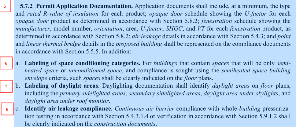

a. A report complying with Section 4.2.5.1.2 providing the results of continuous air barrier compliance
with whole- building pressurization testing in accordance with Section 5.4.3.1.4 or verification of the building envelope in accordance with Section 5.9.1.2. b. Insulation documentation in accordance with Section 5.8.1.11.
5.7.3.2 Manuals. Construction documents shall require that an operating manual and a maintenance manual be provided to the building owner, or the designated representative of the building owner, within 90 days after the date of building envelope acceptance. These manuals shall be in accordance with industryaccepted standards (see Informative Appendix E) and shall include, at a minimum, operation manuals and maintenance manuals for each component of the building envelope requiring maintenance, except components not furnished as part of the project. Required routine maintenance actions shall be clearly identified.
5.8.1.1 Labeling of Building Envelope Insulation. The rated R-value of insulation shall be clearly identified by an identification mark applied by the manufacturer to each piece of building envelope insulation.
Exceptions to 5.8.1.1: When insulation does not have such an identification mark, the rated R-value of
insulation and the additional information specified below shall be identified by the manufacturer on each package, shipping container, or bundle of insulation. Insulation documentation shall be provided in accordance with Section 5.8.1.11 and the following:
- For batts and blankets of any type: The rated R-value of insulation, length, width, thickness.
- For boardstock: The rated R-value of insulation, length, width, and thickness of the boards in the package.
- For all loose-fill insulation: The minimum settled thickness, initial installed thickness, maximum net coverage area, number of bags per 1000 ft [2] and minimum weight per ft [2] at R-values of 13, 19, 30, 38, and 49. The package shall also state the minimum net weight of the insulation in the package.
- For spray-applied polyurethane foam: The R-value for the insulation at a 1 in. thickness and additional inch increments up to the maximum thickness allowed.
5.8.1.2 Manufacturer’s Installation Instructions. Insulation materials shall be installed in accordance with the manufacturer ’s recommendations and in such a manner as to achieve the rated R-value of insulation .
Exceptions to 5.8.1.2:
- The R-value of compressed cavity insulation is determined in accordance with Table A9.4.3.
- Where metal building roof or wall insulation is compressed between the steel structure and the metal roof or wall panels, the overall assembly U-factor is determined in accordance with Section A2.3, Section A3.2, or Section A9.4.6.
66 ANSI/ASHRAE/IES Standard 90.1-2022 (I-P)
PDF Page 69
5.8.1.3 Loose-Fill Insulation Limitation. Open-blown or poured loose-fill insulation shall not be used in attic roof spaces when the slope of the ceiling is more than three in twelve.
5.8.1.4 Baffles. When eave vents are installed, baffling of the vent openings shall be provided to deflect the incoming air above the surface of the insulation.
5.8.1.5 Substantial Contact. Insulation shall be installed in a permanent manner in substantial contact with the inside surface in accordance with the manufacturer ’s recommendations for the framing system used. Flexible batt insulation installed in floor cavities shall be supported in a permanent manner by supports no greater than 24 in. on center.
Exception to 5.8.1.5: Insulation materials that rely on air spaces adjacent to reflective surfaces for their
rated performance.
5.8.1.6 Recessed Equipment. Lighting fixtures ; heating, ventilating, and air-conditioning equipment, including wall heaters, ducts, and plenums ; and other equipment shall not be recessed in such a manner as to affect the insulation thickness unless
a. the total combined area affected (including necessary clearances) is less than 1% of the opaque area of
the assembly, b. the entire roof, wall, or floor is covered with insulation to the full depth required, or c. the effects of reduced insulation are included in calculations using an area-weighted-average method and
compressed insulation values obtained from Table A9.4.3.
In all cases, air leakage through or around the recessed equipment to the conditioned space shall be limited in accordance with Section 5.4.3.
5.8.1.7 Insulation Protection. Exterior insulation shall be covered with a protective material to prevent damage from sunlight, moisture, landscaping operations, equipment maintenance, and wind.
5.8.1.7.1 In attics and mechanical rooms, a way to access equipment that prevents damaging or compressing the insulation shall be provided.
5.8.1.7.2 Foundation vents shall not interfere with the insulation. 5.8.1.7.3 Insulation materials in ground contact shall have a water absorption rate no greater than 0.3% when tested in accordance with ASTM C272.
5.8.1.8 Location of Roof Insulation. The roof insulation shall not be installed on a suspended ceiling with removable ceiling panels.
5.8.1.9 Extent of Insulation. Insulation shall extend over the full component area to the required rated R-value of insulation, U-factor, C-factor, or F-factor, unless otherwise allowed in Section 5.8.1.
5.8.1.10 Joints in Rigid Insulation. Where two or more layers of rigid insulation board are used in a construction assembly, the edge joints between each layer of boards shall be staggered.
5.8.2.1 Rating of Fenestration Products. The U-factor, SHGC, VT, and air leakage rate for all manufactured fenestration products shall be determined by a laboratory accredited by a nationally recognized accreditation organization, such as the National Fenestration Rating Council.
5.8.2.2 Labeling of Fenestration and Door Products. All manufactured and site -built fenestration and
Exception to 5.8.2.2: Doors with less than 25% glazing are not required to list SHGC and VT .
5.8.2.3 Manufacturer’s Installation Instructions. Fenestration products shall be installed in accordance with manufacturer ’s instructions.
5.8.2.4 U-Factor. U-factors shall be determined in accordance with NFRC 100. U-factors for skylights shall be determined for a slope of 20 degrees above the horizontal.
Exceptions to 5.8.2.4:
- U-factors from Section A8.1 shall be an acceptable alternative for determining compliance with the U-factor criteria for skylights . Where credit is being taken for a low-emissivity coating, the emissivity of the coating shall be determined in accordance with NFRC 300. Emissivity shall be verified and certified by the manufacturer .
ANSI/ASHRAE/IES Standard 90.1-2022 (I-P) 67

PDF Page 70
- U-factors from Section A8.2 shall be an acceptable alternative for determining compliance with the U-factor criteria for vertical fenestration .
- U-factors from Section A7 shall be an acceptable alternative for determining compliance with the U-factor criteria for opaque doors .
- For sectional garage doors and metal coiling doors, ANSI/DASMA105 shall be an acceptable alternative for determining U-factors .
5.8.2.5 Solar Heat Gain Coefficient. SHGC for the overall fenestration area shall be determined in accordance with NFRC 200.
Exceptions to 5.8.2.5:
- Shading coefficient ( SC ) of the center-of-glass multiplied by 0.86 shall be an acceptable alternative for determining compliance with the SHGC requirements for the overall fenestration area . SC shall be determined using a spectral data file determined in accordance with NFRC 300. SC shall be verified and certified by the manufacturer .
- SHGC of the center-of-glass shall be an acceptable alternative for determining compliance with the SHGC requirements for the overall fenestration area . SHGC shall be determined using a spectral data file determined in accordance with NFRC 300. SHGC shall be verified and certified by the manufacturer .
- SHGC from Section A8.1 shall be an acceptable alternative for determining compliance with the SHGC criteria for skylights . Where credit is being taken for a low-emissivity coating, the emissivity of the coating shall be determined in accordance with NFRC 300. Emissivity shall be verified and certified by the manufacturer .
- SHGC from Section A8.2 shall be an acceptable alternative for determining compliance with the SHGC criteria for vertical fenestration .
5.8.2.6 Visible Transmittance. VT shall be determined in accordance with NFRC 200. VT shall be verified and certified by the manufacturer .
Exceptions to 5.8.2.6:
- VTannual determined in accordance with NFRC 203 shall be an acceptable alternative for determining compliance with the VT requirements for tubular daylighting devices.
- For skylights whose transmittances are not within the scope of NFRC 200, their transmittance shall be the solar photometric transmittance of the skylight glazing materials determined in accordance with ASTM E972.
5.8.3 Air Leakage 5.8.3.1 Testing, Acceptable Materials, and Assemblies. Air leakage for materials or assemblies used as components of the continuous air barrier shall be determined in accordance with the test method and minimum air pressure specified in Table 5.8.3.1 and shall not exceed the maximum air leakage specified in Table 5.8.3.1 when complying with the continuous air barrier design and installation verification program in accordance with Section 5.9.1.2. Air leakage shall be determined by a laboratory accredited by a nationally recognized accreditation organization.
5.8.3.2 Fenestration and Doors. Air leakage for fenestration and doors shall be determined in accordance with the test method and minimum air pressure specified in Table 5.8.3.2 and shall not exceed the maximum air leakage specified in Table 5.8.3.2 when complying with the continuous air barrier design and installation verification program in accordance with Section 5.9.1.2. Air leakage shall be determined by a laboratory accredited by a nationally recognized accreditation organization and shall be labeled and certified by the manufacturer .
Exceptions to 5.8.3.2:
- Field-fabricated fenestration and doors .
- Metal coiling doors in semiheated spaces in Climate Zones 0 through 6 shall have an air leakage not exceeding 1.0 cfm/ft [2] when tested at a pressure of at least 1.57 psf in accordance with ANSI/ DASMA 105, NFRC 400, or ASTM E283.
- Products in buildings that are tested and shown to comply with a whole- building air leakage in accordance with Section 5.4.3.1.4.
5.9 Verification, Testing, and Commissioning 5.9.1 Verification and Testing 5.9.1.1 Building Envelope Performance Verification. The building envelope shall be verified in
68 ANSI/ASHRAE/IES Standard 90.1-2022 (I-P)
PDF Page 71
Table 5.8.3.1 Maximum Air Leakage for Materials and Assemblies
| Continuous Air Barrier | Maximum Air Leakage, cfm/ft2 | Minimum Test Pressure, psf | Test Method |
|---|---|---|---|
| Materials a | 0.004 | 1.57 | ASTM E2178 |
| Assemblies b | 0.04 | 1.57 | ASTM E2357, ASTM E1677, ASTM E1680, ASTM E283 |
a. The following materials comply with the requirements in Table 5.8.3.1:
-
Plywood—minimum 3/8 in.
-
Oriented strand board—minimum 3/8 in.
-
Extruded polystyrene insulation board—minimum 1/2 in.
-
Foil-faced polyisocyanurate insulation board—minimum 1/2 in.
-
Exterior gypsum sheathing or interior gypsum board—minimum 1/2 in.
-
Cement board—minimum 1/2 in.
-
Built-up roofing membrane
-
Modified bituminous roof membrane
-
Single-ply roof membrane
-
A Portland cement/sand parge, stucco, or gypsum plaster—minimum 1/2 in. thick
-
Cast-in-place and precast concrete
-
Sheet metal
-
Closed-cell 2 lb/ft [3] nominal density spray polyurethane foam—minimum 1 in. b. The following assemblies comply with the requirements in Table 5.8.3.1:
-
Concrete masonry walls that are (a) fully grouted or (b)painted to fill the pores
-
Shale or clay masonry units that are assembled as a solid wall : without weeps, with nominal width of 4 in. or more, and with Type S mortar
| Table 5.8.3.2 Maximum Air Leakage for Fenestration and Doors | Col2 | Col3 | Col4 |
|---|---|---|---|
| Fenestration and Door Products | Maximum Air Leakage, cfm/ft2 | Minimum Test Pressure, psf | Test Methods |
| Glazed swinging_entrance doors_, glazed power-operating sliding_entrance_ doors, glazed power-operated folding_entrance doors_, and revolving_doors_ | 1.0 | 1.57 | AAMA/WDMA/CSA 101/I.S.2/A440, NFRC 400, or ASTM E283; |
| Curtainwall and storefront glazing | 0.06 | 1.57 | NRFC 400 or ASTM 283 |
| Unit_skylights_ having condensation weepage openings | 0.3 | 1.57 | AAMA/WDMA/CSA 101/I.S.2/A440 or NFRC 400 |
| Unit_skylights_ having condensation weepage openings | OR | OR | OR |
| Unit_skylights_ having condensation weepage openings | 0.5 | 6.24 | AAMA/WDMA/CSA 101/I.S.2/A440 |
| Nonswinging doors intended for vehicular access and material transportation, with a minimum opening rate of 32 in./s | 1.3 | 1.57 | ANSI/DASMA 105, NFRC 400, or ASTM E283 |
| Other_opaque nonswinging doors_, glazed_sectional garage doors_, and upward acting glazed_nonswinging_ | 0.4 | 1.57 | ANSI/DASMA 105, NFRC 400, or ASTM E283 |
| All other products | 0.2 | 1.57 | AAMA/WDMA/CSA 101/I.S.2/A440 or NFRC 400 |
| All other products | OR | OR | OR |
| All other products | 0.3 | 6.24 | AAMA/WDMA/CSA 101/I.S.2/A440 |
ANSI/ASHRAE/IES Standard 90.1-2022 (I-P) 69
PDF Page 72
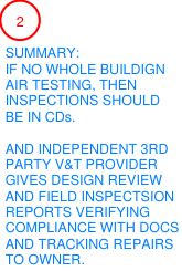
5.9.1.2 Verification of the Design and Installation of the Continuous Air Barrier. Where verification of the design and installation of the continuous air barrier is used for compliance in Section 5.4.3.1, it shall be determined in accordance with the following:
- plan.Verification and “FUNCTIONAL PERFORMANCE TESTING” = VERIFY AB IS FUNCTIONING FPT documentation shall comply with Section 4.2.5.1.2 and the field inspection V&T PROVIDER CERT COMPLETION OF FPT PLAN DEFERRED FPT, TO OWNER. 5.9.1.3 Dynamic Glazing. Dynamic glazing operation shall be tested for conformance with the manu- facturer’s installation instructions.
AB DOC AB FENEST
“FUNCTIONAL PERFORMANCE TESTING” = VERIFY AB IS FUNCTIONING V&T PROVIDER CERT COMPLETION OF FPT PLAN DEFERRED FPT, TO OWNER.
5.9.1.4 Air Curtains. Air curtains shall comply with Section 10.4.5. 5.9.2 Commissioning. The energy performance of the building envelope shall be commissioned i n accordance with Section 4.2.5.2. Commissionin g reporting shall comply with Section 4.2.5.2.2.
Informative Note: See Informative Appendix E and Informative Appendix H for commissioning references and guidance.
70 ANSI/ASHRAE/IES Standard 90.1-2022 (I-P)
PDF Page 73
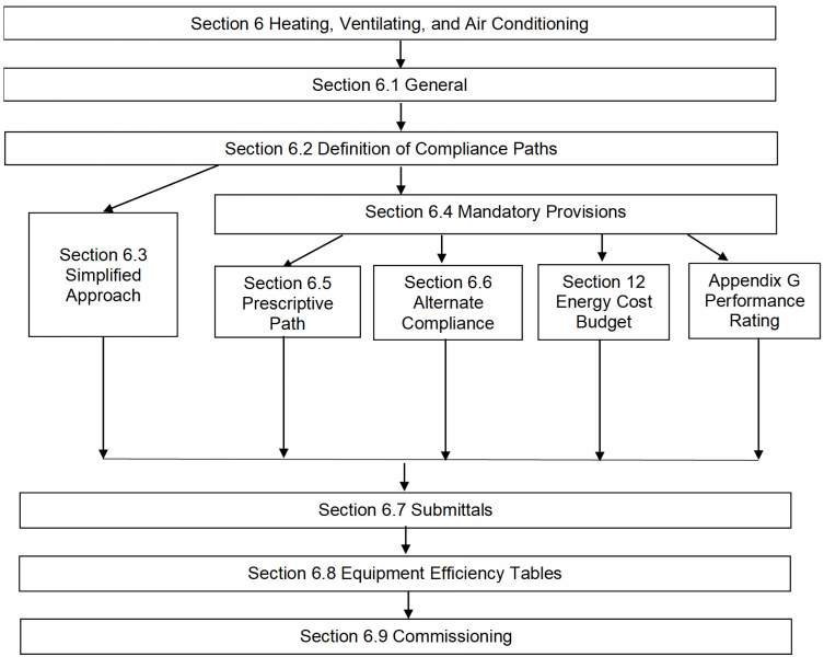
6. HEATING, VENTILATING, AND AIR CONDITIONING
6.1 General 6.1.1 Scope. Section 6 specifies requirements for mechanical equipment and systems. 6.1.2 New Buildings. Mechanical equipment and systems serving the heating, cooling, ventilating, or refrigeration needs of new buildings shall comply with the requirements of this section as described in Section 6.2.
6.1.3 Additions to Existing Buildings. Mechanical equipment and systems serving the heating, cooling, ventilating, or refrigeration needs of additions to existing buildings shall comply with the requirements of this section as described in Section 6.2.
Exception to 6.1.3: When HVACR to an addition is provided by existing HVACR systems and equip-
ment, such existing systems and equipment shall not be required to comply with this standard. However, any new systems or equipment installed must comply with specific requirements applicable to those systems and equipment .
6.1.4 Alterations to Heating, Ventilating, Air Conditioning, and Refrigeration in Existing Buildings 6.1.4.1 New HVACR equipment as a direct replacement of existing HVACR equipment shall comply with the following sections as applicable for the equipment being replaced:
a. 6.3, “Simplified Approach Building Compliance Path for HVAC Systems” b. 6.4.1, “Equipment Efficiencies, Verification, and Labeling Requirements” c. 6.4.3.1, “Zone Thermostatic Controls” d. 6.4.3.2, “Set-Point Overlap Restrictions” e. 6.4.3.3, “Off-Hour Controls” except for Section 6.4.3.3.4, “Zone Isolation” f. 6.4.3.4, “Ventilation System Controls” g. 6.4.3.7, “Freeze Protection and Snow/Ice Melting Systems” h. 6.4.3.8, “Ventilation Controls for High-Occupancy Areas” only for single-zone equipment i. 6.4.3.9, “Heated or Cooled Vestibules or Air Curtains with Integral Heating” j. 6.4.5, “Walk-In Coolers and Walk-In Freezers” k. 6.5.1.1, “Air Economizers” for units located outdoors l. 6.5.1.3, “Integrated Economizer Control” m. 6.5.1.4, “Economizer Heating System Impact” n. 6.5.3.1.3, “Fan Efficiency”
ANSI/ASHRAE/IES Standard 90.1-2022 (I-P) 71
PDF Page 74
o. 6.5.3.2.1, “Supply Fan Airflow Control” p. 6.5.3.6, “Fractional Horsepower Fan Motors” q. 6.5.4.1, “Boiler Turndown” r. 6.5.4.3, “Chiller and Boiler Isolation” s. 6.5.5.2, “Fan Speed Control”
6.1.4.2 New cooling systems installed to serve previously uncooled spaces shall comply with this section as described in Section 6.2.
6.1.4.3 Alterations to existing cooling systems shall not decrease economizer capability unless the sys- tem complies with Section 6.5.1.
6.1.4.4 New and replacement ductwork shall comply with Sections 6.4.4.1 and 6.4.4.2. 6.1.4.5 New and replacement piping shall comply with Section 6.4.4.1. Exceptions to 6.1.4.5: Compliance shall not be required
- for equipment that is being modified or repaired but not replaced, provided that such modifications and/or repairs will not result in an increase in the annual energy consumption of the equip- ment using the same energy type;
- where a replacement or alteration of equipment requires extensive revisions to other systems, equipment, or elements of a building, and such replaced or altered equipment is a like-for-like replacement;
- for a refrigerant change of existing equipment ;
- for the relocation of existing equipment ; or
- for ducts and piping where there is insufficient space or access to meet these requirements.
6.1.5 Climate. Climate zones shall be determined in accordance with Section 5.1.5.
6.2 Compliance Paths. Mechanical equipment and systems providing heating, cooling, ventilating, or refrigeration shall comply with Sections 6.2.1 and 6.2.2.
6.2.1 Requirements for all Compliance Paths. Mechanical equipment and systems shall comply with all of the following:
a. Section 6.1, “General” b. Section 6.4, “Mandatory Provisions”
Exception to 6.2.1(b): When compliance is shown using Section 6.2.2(a), compliance with Section 6.4
is not required unless required in Section 6.3.2. c. Section 6.7, “Submittals” d. Section 6.8, “Minimum Equipment Efficiency Tables”
6.2.2 Additional Requirements to Comply with Section 6. Refrigeration equipment and systems shall comply with Section 6.5, “Prescriptive Compliance Path.” All building HVAC systems shall comply with one of the following:
a. Section 6.3, “Simplified Approach Building Compliance Path for HVAC Systems” b. Section 6.5, “Prescriptive Compliance Path” c. Section 6.6.1, “Computer Room System Path” d. Section 6.6.2, “Mechanical System Performance Path”
Informative Note: Section 6.3 requires all HVAC systems in the building to qualify for the simplified path. Section 6.6.2 requires all allowable systems to meet Normative Appendix L requirements. Section 6.6.2 does allow part of the building to use the Mechanical System Performance Path and part of the building to use Section 6.5 where there are excluded occupancy types or system types in Section L1.1.1.2. HVAC sys- tems for larger computer rooms may comply with either Section 6.5, Section 6.6.1, or Section 6.6.2.
6.3 Simplified Approach Building Compliance Path for HVAC Systems 6.3.1 Scope. The simplified approach is an optional path for compliance when the following conditions are met:
a. The building is two stories or fewer in height. b. Gross floor area is less than 25,000 ft [2] . c. Each HVAC system in the building complies with the requirements listed in Section 6.3.2.
6.3.2 Criteria. The HVAC system must meet all of the following criteria:
a. The system serves a single HVAC zone . b. The equipment must meet the variable flow requirements of Section 6.5.3.2.1.
72 ANSI/ASHRAE/IES Standard 90.1-2022 (I-P)
PDF Page 75
c. Cooling (if any) shall be provided by a unitary packaged or split- system air conditioner that is either air
cooled or evaporatively cooled, with efficiency meeting the requirements shown in Table 6.8.1-1 (air conditioners), Table 6.8.1-2 (heat pumps), or Table 6.8.1-4 (packaged terminal and room air condition- ers and heat pumps) for the applicable equipment category. Cooling equipment shall also comply with Section 6.4.1.4. d. The system shall have an air economizer meeting the requirements of Sections 6.5.1 and 6.4.3.12. e. Heating (if any) shall be provided by a unitary packaged or split- system heat pump that meets the appli cable efficiency requirements shown in Table 6.8.1-2 (heat pumps) or Table 6.8.1-4 (packaged terminal and room air conditioners and heat pumps), a fuel -fired furnace that meets the applicable efficiency requirements shown in Table 6.8.1-5 (furnaces, duct furnaces, and unit heaters), an electric resistance heater, or a baseboard system connected to a boiler that meets the applicable efficiency requirements shown in Table 6.8.1-6 ( boilers ). Heating equipment shall also comply with Section 6.4.1.4. f. The system shall meet the exhaust air energy recovery requirements of Section 6.5.6.1. g. The system shall be controlled by a manual changeover or dual set-point thermostat . h. If a heat pump equipped with auxiliary internal electric resistance heaters is installed, controls shall be
provided that prevent supplemental heater operation when the heating load can be met by the heat pump alone during both steady-state operation and setback recovery. Supplemental heater operation is permitted during outdoor coil defrost cycles. The heat pump must be controlled by either (1) a digital or electronic thermostat designed for heat pump use that energizes auxiliary heat only when the heat pump has insufficient capacity to maintain set point or to warm up the space at a sufficient rate or (2) a multistage space thermostat and an outdoor air thermostat wired to energize auxiliary heat only on the last stage of the space thermostat and when outdoor air temperature is less than 40°F. Exceptions to 6.3.2.(h): Heat pumps that comply with the following:
- Have a minimum efficiency regulated by NAECA.
- Meet the requirements in Table 6.8.1-2.
- Include all usage of internal electric resistance heating. i. The system controls shall not permit reheat or any other form of simultaneous heating and cooling for humidity control. Exception to 6.3.2(i): Humidity control assisted by hot-gas reheat or heat from 100% site-recovered
energy is permitted. j. Systems serving spaces other than residential spaces, that do not require continuous operation, with a cooling or heating capacity greater than 7000 Btu/h shall comply with Sections 6.4.3.3.1 and 6.4.3.3.2. k. Systems serving residential spaces other than hotel/motel guest rooms shall comply with Sections
6.4.3.3.1 and 6.4.3.3.2 except for electric resistance heaters rated at 2 hp or less with a readily accessible manual control that lowers the set point or turns the unit off. l. Systems serving hotel/motel guest rooms shall comply with Section 6.4.3.3.5. m. Except for piping within manufacturers ’ units, HVAC piping shall be insulated in accordance with
Tables 6.8.3-1 and 6.8.3-2. Insulation exposed to weather shall be suitable for outdoor service, e.g., protected by aluminum, sheet metal, painted canvas, or plastic cover. Cellular foam insulation shall be protected as above or painted with a coating that is water retardant and provides shielding from solar radiation. n. Ductwork and plenums shall be insulated in accordance with Table 6.8.2 and shall be sealed in accor dance with Section 6.4.4.2.1. o. Construction documents shall require a ducted system to be air balanced in accordance with industry
accepted procedures. p. Outdoor air intake and exhaust systems shall meet the requirements of Section 6.4.3.4. q. Where separate heating and cooling equipment serves the same temperature zone, thermostats shall be
interlocked to prevent simultaneous heating and cooling. r. Systems with a design supply air capacity greater than 10,000 cfm shall have optimum start controls . s. The system shall comply with the demand control ventilation requirements in Section 6.4.3.8, occupiedstandby controls in Section 6.5.3.9, and the ventilation design requirements in Section 6.5.3.8. t. The system complies with the door switch requirements in Section 6.5.10.
6.4 Mandatory Provisions 6.4.1 Equipment Efficiencies, Verification, and Labeling Requirements 6.4.1.1 Minimum Equipment Efficiencies—Listed Equipment—Standard Rating and Operating Conditions. Equipment shown in Tables 6.8.1-1 through 6.8.1-21 shall have a minimum performance at the specified rating conditions when tested in accordance with the specified test procedure. Where multiple rating
ANSI/ASHRAE/IES Standard 90.1-2022 (I-P) 73
PDF Page 76
conditions or performance requirements are provided, the equipment shall satisfy all stated requirements unless otherwise exempted by footnotes in the table. Equipment covered under the Federal Energy Policy Act of 1992 (EPACT) shall have no minimum efficiency requirements for operation at minimum capacity or other than standard rating conditions. Equipment used to provide service water-heating functions as part of a combination system shall satisfy all stated requirements for the appropriate space heating or cooling category.
Tables are as follows:
a. Table 6.8.1-1, “Electrically Operated Unitary Air Conditioners and Condensing Units—Minimum Effi ciency Requirements” b. Table 6.8.1-2, “Electrically Operated Air-Cooled Unitary Heat Pumps—Minimum Efficiency Require ments” c. Table 6.8.1-3, “Liquid-Chilling Packages—Minimum Efficiency Requirements” (See Section 6.4.1.2 for
liquid-cooled centrifugal liquid-chilling packages that are designed to operate at nonstandard conditions.) d. Table 6.8.1-4, “Electrically Operated Packaged Terminal Air Conditioners, Packaged Terminal Heat
Pumps, Single-Package Vertical Air Conditioners, Single-Package Vertical Heat Pumps, Room Air Conditioners, and Room Air Conditioner Heat Pumps—Minimum Efficiency Requirements” e. Table 6.8.1-5, “Warm-Air Furnaces and Combination Warm-Air Furnaces/Air-Conditioning Units,
Warm-Air Duct Furnaces, and Unit Heaters—Minimum Efficiency Requirements” f. Table 6.8.1-6, “Gas- and Oil-Fired Boilers—Minimum Efficiency Requirements” g. Table 6.8.1-7, “Performance Requirements for Heat-Rejection Equipment—Minimum Efficiency
Requirements” h. Table 6.8.1-8, “Electrically Operated Variable-Refrigerant-Flow Air Conditioners—Minimum Effi ciency Requirements” i. Table 6.8.1-9, “Electrically Operated Variable-Refrigerant-Flow and Applied Heat Pumps—Minimum Efficiency Requirements j. Table 6.8.1-10, “Floor-Mounted Air Conditioners and Condensing Units Serving Computer Rooms— Minimum Efficiency Requirements” k. Table 6.8.1-11, “Commercial Refrigerators, Commercial Freezers, and Refrigeration—Minimum Effi ciency Requirements” l. Table 6.8.1-12, “Vapor-Compression-Based Indoor Pool Dehumidifiers—Minimum Efficiency Requirements” m. Table 6.8.1-13, “Electrically Operated DX-DOAS Units, Single-Package and Remote Condenser, with out Energy Recovery—Minimum Efficiency Requirements” n. Table 6.8.1-14, “Electrically Operated DX-DOAS Units, Single-Package and Remote Condenser, with
Energy Recovery—Minimum Efficiency Requirements” o. Table 6.8.1-15, “Electrically Operated Water-Source Heat Pumps—Minimum Efficiency Requirements” p. Table 6.8.1-16, “Heat Pump and Heat Recovery Water-Chilling Packages—Minimum Efficiency
Requirement” q. Table 6.8.1-17, “Ceiling-Mounted Computer-Room Air Conditioners—Minimum Efficiency Require ments” r. Table 6.8.1-18, “Walk-In Cooler and Freezer Display Door Efficiency Requirements” s. Table 6.8.1-19, “Walk-In Cooler and Freezer Nondisplay Door Efficiency Requirements” t. Table 6.8.1-20, “Walk-In Cooler and Freezer Refrigeration System Efficiency Requirements” u. Table 6.8.1-21, “Ceiling Fan Efficiency Requirements”
6.4.1.2 Minimum Equipment Efficiencies—Listed Equipment—Nonstandard Conditions 6.4.1.2.1 Liquid-Cooled Centrifugal Chilling Package Cooling Efficiency Adjustment. Liquidcooled centrifugal chiller packages not designed for cooling operation at AHRI Standard 550/590 test and rating conditions of 44.00°F leaving and 54.00°F entering chilled-liquid temperatures, and with 85.00°F entering and 94.30°F leaving condenser-liquid temperatures, shall have maximum full-load kW /ton (FL) and part-load cooling energy efficiency ( IPLV .IP) rating requirements, listed in Tables 6.8.1-3 and 6.8.1-16, adjusted using the following equations:
FL.IP adj = FL.IP/ Kadj PLV.IP adj = IPLV .IP/ Kadj
Kadj = A × B
where
74 ANSI/ASHRAE/IES Standard 90.1-2022 (I-P)
PDF Page 77
FL.IP = full-load kW /ton value from Table 6.8.1-3 or 6.8.1-16
FL.IP adj = maximum full-load kW /ton rating, adjusted for nonstandard conditions
IPLV. IP = IPLV. IP value from Table 6.8.1-3 or 6.8.1-16
PLV . IP adj = maximum NPLV. IP rating, adjusted for nonstandard conditions
A = 0.00000014592 × (LIFT) [4] - 0.0000346496 × (LIFT) [3 ] + 0.00314196 × (LIFT) [2] - 0.147199 × (LIFT) + 3.93073
B = 0.0015 × LvgEvap + 0.934
LIFT = LvgCond – LvgEvap
LvgCond = full-load condenser leaving liquid temperature, °F
LvgEvap = full-load evaporator leaving liquid temperature, °F
The FL . IP adj and PLV . IP adj values are only applicable for centrifugal chilling packages meeting all of the following full-load design ranges:
-
36.00°F LvgEvap 70.00°F and
-
60.00°F LvgCond 135.00°F and
-
20.00°F LIFT 80.00°F
Manufacturers shall calculate the FL.IP adj and PLV.IP adj before determining whether to label the chiller per Section 6.4.1.5. Compliance with Standard 90.1-2007, 2010, 2013, 2016, 2019, 2022, or combinations thereof, shall be labeled on chilling packages within the scope of the standard.
Centrifugal chilling packages designed to operate outside of these ranges are not covered by this standard.
6.4.1.2.2 Chilling Packages Employing Freeze-Protection Liquids. Electrically operated chilling packages that employ freeze-protection liquids in any heat exchanger with an application cooling duty evaporator liquid leaving temperature or heating operation source liquid temperature above 32.00°F shall show efficiency compliance in accordance with the applicable requirements in Sections 6.4.1.2.2.1 through 6.4.1.2.2.4. Absorption chilling packages with freeze-protection liquids are exempt from the efficiency requirements listed in Table 6.8.1-3 and shall only show compliance when applied with water.
6.4.1.2.2.1 All electrically operated cooling-only air-cooled and electrically operated positive displacement liquid-cooled chilling packages shall show compliance with the cooling efficiency requirements listed in Table 6.8.1-3when applied within the operating limits of AHRI 550/590 at AHRI 550/590 standard rating conditions when tested or rated with water used as a heat transfer liquid.
6.4.1.2.2.2 All liquid-cooled electrically operated cooling-only centrifugal chilling packages shall show compliance with the cooling efficiency requirements listed in Table 6.8.1-3 when applied within the operating limits defined in AHRI 550/590 at the application rating conditions for a cooling efficiency, adjusted using Kadj as defined in Section 6.4.1.2.1, when tested or rated with water used as a heat transfer liquid.
6.4.1.2.2.3 All electrically operated air source and electrically operated positive displacement liquidsource heat pump and heat recovery chilling packages shall show compliance with the cooling efficiency requirements listed in Table 6.8.1-16 when applied within the operating limits of AHRI 550/590 at AHRI 550/ 590 standard rating conditions when tested or rated with water used as a heat transfer liquid. They also shall show compliance with the heating efficiency requirements listed in Table 6.8.1-16 at one of the AHRI 550/590 standard heating rating conditions when tested or rated with water used as a heat transfer liquid. Heating-only chilling packages shall meet the efficiency requirements at one of the AHRI 550/590 heating liquid temperature rating conditions and are not required to meet the cooling efficiency requirements of Table 6.8.1-16.
6.4.1.2.2.4 All liquid-source centrifugal heat pump and heat recovery chilling packages shall show compliance with the cooling efficiency requirements listed in Table 6.8.1-16 when applied within the operating limits defined in AHRI 550/590 at the application rating conditions for cooling efficiency, adjusted using Kadj as defined in Section 6.4.1.2.1, when tested or rated with water. They also shall show compliance with the heating efficiency requirements in Table 6.8.1-16 at one of the AHRI 550/590 standard rating conditions when tested or rated with water used as a heat-transfer liquid. Heating-only chilling packages shall meet the heating efficiency requirements at one of the AHRI 550/590 heating liquid temperature rating conditions and are not required to meet the cooling efficiency requirements of Table 6.8.1-16.
6.4.1.3 Equipment not Listed. Equipment not listed in the tables referenced in Sections 6.4.1.1 and 6.4.1.2 may be used.
ANSI/ASHRAE/IES Standard 90.1-2022 (I-P) 75
PDF Page 78
6.4.1.4 Verification of Equipment Efficiencies. Equipment efficiency information supplied by manu- facturers shall be verified by one of the following:
a. Equipment covered under EPACT shall comply with U.S. Department of Energy certification require ments. b. If a certification program exists for a covered product, and it includes provisions for verification and
challenge of equipment efficiency ratings, then the product shall be listed in the certification program. c. If a certification program exists for a covered product, and it includes provisions for verification and
challenge of equipment efficiency ratings, but the product is not listed in the existing certification program, the ratings shall be verified by an independent laboratory test report. d. If no certification program exists for a covered product, the equipment efficiency ratings shall be sup ported by data furnished by the manufacturer . e. Where components such as indoor or outdoor coils from different manufacturers are used, the system
designer shall specify component efficiencies whose combined efficiency meets the minimum equipment efficiency requirements in Section 6.4.1. 6.4.1.5 Labeling 6.4.1.5.1 Mechanical Equipment. Mechanical equipment that is not covered by the U.S. National Appliance Energy Conservation Act (NAECA) of 1987 shall carry a permanent label installed by the manu- facturer stating that the equipment complies with the requirements of Standard 90.1.
6.4.1.5.2 Packaged Terminal Air Conditioners. Nonstandard-size packaged terminal air condition- ers and heat pumps with existing sleeves having an external wall opening of less than 16 in. high or less than 42 in. wide and having a cross-sectional area less than 670 in. [2] shall be factory labeled as follows: “Manufactured for nonstandard-size applications only: Not to be installed in new construction projects.”
6.4.2 Calculations 6.4.2.1 Load Calculations. Heating and cooling system design loads for the purpose of sizing systems and equipment shall be determined in accordance with ASHRAE/ACCA Standard 183.
6.4.2.2 Pump Head. Pump differential pressure (head) for the purpose of sizing pumps shall be determined in accordance with generally accepted engineering standards and handbooks acceptable to the adopt- ing authority . The pressure drop through each device and pipe segment in the critical circuit at design conditions shall be calculated.
6.4.3 Controls and Diagnostics 6.4.3.1 Zone Thermostatic Controls 6.4.3.1.1 General. The supply of heating and cooling energy to each zone shall be individually controlled by thermostatic controls responding to temperature within the zone. For the purposes of this section, a dwelling unit shall be permitted to be considered a single zone.
Exceptions to 6.4.3.1.1: Independent perimeter systems that are designed to offset only building enve-
lope loads shall be permitted to serve one or more zones also served by an interior system, provided that
- the perimeter system includes at least one thermostatic control zone for each building exposure having walls facing only one orientation for 50 contiguous feet or more and
- the perimeter system heating and cooling supply is controlled by thermostatic controls located within the zones served by the system .
Exterior walls and semiexterior walls are considered to have different orientations if the exposures they face differ by more than 45 degrees. 6.4.3.1.2 Dead Band. Where used to control both heating and cooling, zone thermostatic controls shall be capable of and configured to provide a temperature range or dead band of at least 5°F within which the supply of heating and cooling energy to the zone is shut off or reduced to a minimum.
Exceptions to 6.4.3.1.2:
- Thermostats that require manual changeover between heating and cooling modes.
- Special occupancy or special applications where wide temperature ranges are not acceptable (such as retirement homes, process applications, museums, some areas of hospitals) and are approved by the authority having jurisdiction .
6.4.3.2 Set-Point Overlap Restriction. Where heating and cooling to a zone are controlled by separate zone thermostatic controls located within the zone, means (such as limit switches; mechanical stops; or, for DDC systems, software programming) shall be provided to prevent the heating set point from exceeding the cooling set point, minus any applicable proportional band.
76 ANSI/ASHRAE/IES Standard 90.1-2022 (I-P)
PDF Page 79
6.4.3.3 Off-Hour Controls. HVAC systems shall have the off-hour controls required by Sections 6.4.3.3.1 through 6.4.3.3.5. Exceptions to 6.4.3.3:
- HVAC systems intended to operate continuously.
- HVAC systems not serving residential spaces and having a design heating capacity and cooling capacity less than 7000 Btu/h that are equipped with readily accessible manual on/off controls .
6.4.3.3.1 Automatic Shutdown. HVAC systems shall be equipped with at least one of the following:
a. Controls that can start and stop the system under different time schedules for seven different day types
per week, are capable of retaining programming and time setting during loss of power for a period of at least ten hours, and include an accessible manual override or equivalent function that allows temporary operation of the system for up to two hours. b. An occupancy sensor that is capable of shutting the system off when no occupant is sensed for a period
of up to 30 minutes. c. A manually operated timer capable of being adjusted to operate the system for up to two hours. d. An interlock to a security system that shuts the system off when the security system is activated.
Exceptions to 6.4.3.3.1:
- Systems serving residential occupancies with controls that can start and stop the system under at least two different time schedules per week.
- Systems serving non- residential occupancies where heating or cooling capacity is less than 15,000 Btu/h, with controls that can start and stop the system under at least two different time schedules per week.
6.4.3.3.2 Setback Controls. Heating systems shall be equipped with controls capable of and configured to automatically restart and temporarily operate the system as required to maintain zone temperatures above an adjustable heating set point at least 10°F below the occupied heating set point . Cooling systems shall be equipped with controls capable of and configured to automatically restart and temporarily operate the mechanical cooling system at the lowest practical fan speed as required to maintain zone temperatures below an adjustable cooling set point at least 5°F above the occupied cooling set point or to prevent maximum space humidity levels as required by Standard 62.1.
Exception to 6.4.3.3.2: Radiant heating systems capable of and configured with a setback heating set
point at least 4°F below the occupied heating set point .
6.4.3.3.3 Optimum Start Controls. Individual heating and cooling systems with setback controls and DDC shall have optimum start controls . The control algorithm shall, as a minimum, be a function of the difference between space temperature and occupied set point, the outdoor temperature, and the amount of time prior to scheduled occupancy. Mass radiant floor slab systems shall incorporate floor temperature into the optimum start algorithm.
Exception to 6.4.3.3.3 : Residential spaces are not required to have optimum start controls .
6.4.3.3.4 Zone Isolation. HVAC systems serving zones that are intended to operate or be occupied nonsimultaneously shall be divided into isolation areas. Zones may be grouped into a single isolation area provided it does not exceed 25,000 ft [2] of conditioned floor area nor include more than one story . Each isolation area shall be equipped with isolation devices capable of and configured to automatically shut off the supply of conditioned air and outdoor air to and exhaust air from the area. Each isolation area shall be controlled independently by a device meeting the requirements of Sections 6.4.3.3.1. For central systems and plants, controls and devices shall be provided to allow stable system and equipment operation for any length of time while serving only the smallest isolation area served by the system or plant.
Exceptions to 6.4.3.3.4: Isolation devices and controls are not required for
- exhaust air and outdoor air connections to isolation zones when the fan system to which they connect is 5000 cfm and smaller;
- exhaust airflow from a single isolation zone of less than 10% of the design airflow of the exhaust system to which it connects; or
- zones intended to operate continuously or intended to be inoperative only when all other zones are inoperative.
Informative Note: ASHRAE Guideline 36 includes detailed sequences of control for zone isolation using logical groups of zone air terminal units serving each isolation area.
ANSI/ASHRAE/IES Standard 90.1-2022 (I-P) 77
PDF Page 80
6.4.3.3.5 Automatic Control of HVAC in Hotel/Motel Guest Rooms. Hotels and motels with greater than 50 guest rooms shall be provided with automatic controls for the HVAC equipment serving each guest room capable of and configured according to the requirements in the following subsections.
6.4.3.3.5.1 Guest Room HVAC Set-Point Control. HVAC systems serving hotel guest rooms shall be capable of and configured with three modes of temperature control.
a. Rented and unoccupied. Within 20 minutes of all occupants leaving the guest room, HVAC set points
shall be automatically raised by at least 4°F from the occupant set point in the cooling mode and auto- matically lowered by at least 4°F from the occupant set point in the heating mode. b. Unrented and unoccupied. HVAC set points shall be automatically reset to 80°F or higher in the cool ing mode and to 60°F or lower in the heating mode. The HVAC set points in the unrented and unoccupied guest room modes shall be initiated within 16 hours of the guest room being continuously unoccupied or within 20 minutes of the guest room being continuously unoccupied where a networked guest room control system indicates the guest room is unrented. c. Occupied. HVAC set points shall return to their occupied set points once occupancy is sensed.
Exceptions to 6.4.3.3.5.1:
- A networked guest room control system shall be permitted to return the thermostat set points to their default occupied set points 60 minutes prior to the time the room is scheduled to be occupied.
- Dehumidification shall be permitted to limit the space humidity levels as required by Standard 62.1 during unoccupied mode for both rented and unrented periods.
6.4.3.3.5.2 Guest Room Ventilation Control. Within 20 minutes of all occupants leaving the guest room, ventilation and exhaust fans shall automatically be turned off, or isolation devices serving each guest room shall automatically shut off the supply of outdoor air to the guest room and shut off exhaust air from the guest room.
Exception to 6.4.3.3.5.2: Guest room ventilation systems shall be permitted to have an automatic
daily preoccupancy purge cycle that provides daily outdoor air ventilation during unrented periods at the design ventilation rate for 60 minutes, or at a rate and duration equivalent to one air change.
6.4.3.4 Ventilation System Controls 6.4.3.4.1 Stair and Elevator Shaft Vent Dampers. Where stair and elevator shafts have vents, they shall be equipped with motorized dampers that are capable of and configured to automatically close during normal building operation and are interlocked to open as required by fire and smoke detection systems or by thermostatic control systems .
Exception to 6.4.3.4.1: Nonmotorized gravity backdraft dampers are acceptable in buildings less than
three stories in height and for buildings of any height located in Climate Zones 0, 1, 2, and 3.
6.4.3.4.2 Shutoff Damper Controls. All outdoor air intake and exhaust systems shall be equipped with motorized dampers that will automatically shut when the systems or spaces served are not in use. Out- door air and exhaust/relief dampers shall be capable of and configured to automatically shut off during preoccupancy building warm-up, cooldown, and setback, except when the supply of outdoor air reduces energy costs or when outdoor air must be supplied to meet code requirements.
Exceptions to 6.4.3.4.2:
- Nonmotorized (gravity backdraft) dampers are acceptable for exhaust and relief in buildings less than three stories in height and for outdoor air intakes and exhaust and relief dampers in buildings of any height located in Climate Zones 0, 1, 2, and 3. Nonmotorized dampers for out- door air intakes must be protected from direct exposure to wind.
- Nonmotorized dampers are acceptable in systems with a design outdoor air intake or exhaust capacity of 300 cfm or less.
- Dampers are not required in ventilation or exhaust systems serving unconditioned spaces .
- Dampers are not required in exhaust systems serving Type 1 kitchen exhaust hoods.
- Dampers are not required in systems intended to operate continuously.
6.4.3.4.3 Damper Leakage. Where outdoor air supply and exhaust/relief dampers are required by Section 6.4.3.4.1, they shall have a maximum leakage rate as indicated in Table 6.4.3.4.3.
6.4.3.4.4 Ventilation Fan Controls. Fans with motors greater than 0.75 hp shall have automatic con- trols complying with Section 6.4.3.3.1 that are capable of and configured to shut off fans when not required.
Exception to 6.4.3.4.4: HVAC systems intended to operate continuously.
78 ANSI/ASHRAE/IES Standard 90.1-2022 (I-P)
PDF Page 81
Table 6.4.3.4.3 Maximum Damper Leakage [a,b] , cfm per ft [2] at 1.0 in. of water
| Climate Zone | Outdoor Air Intake | Col3 | Exhaust/Relief | Col5 |
|---|---|---|---|---|
| Climate Zone | Nonmotorized a | Motorized | Nonmotorized c | Motorized |
0, 1, 2
Any height 20 4 20 4
3
Any height 20 10 20 10
4, 5B, 5C
| Fewer than three stories | 20 d | 10 | 20 | 10 |
|---|---|---|---|---|
| Three or more_stories_ | 20 d | 10 | 20 d | 10 |
| 5A, 6, 7, 8 | Col2 | Col3 | Col4 | Col5 |
|---|---|---|---|---|
| Fewer than three stories | 20 d | 4 | 20 | 4 |
| Three or more_stories_ | 20 d | 4 | 20 d | 4 |
a. When tested in accordance with AMCA Standard 500-D. b. Dampers smaller than 12 in. in height, width, or diameter need not be tested but shall be of the same design and construction as the smallest tested damper
meeting the listed leakage rate requirement. c. Nonmotorized dampers smaller than 24 in. in height, width, or diameter may have a leakage rate of 40 cfm/ft [2] . d. Where allowed by Section 6.4.3.4.2, Exception 2.
6.4.3.4.5 Parking Garage Ventilation Systems. Parking garage ventilation systems shall meet all of the following:
a. Separate ventilation systems and control systems shall be provided for each parking garage section . b. Control systems for each parking garage section shall automatically detect and control contaminant lev els and shall be capable of and configured to reduce airflow to 20% or less of design capacity . c. The ventilation system for each parking garage section shall have controls and devices that result in fan
motor demand of no more than 30% of design wattage at 50% of the design airflow.
Exception to 6.4.3.4.5: Garage ventilation systems serving a single parking garage section having a
total ventilation system motor nameplate horsepower not exceeding 5 hp at fan system design con- ditions and where the parking garage section has no mechanical cooling or mechanical heating .
6.4.3.5 Heat-Pump Auxiliary Heat Control. Heat pumps equipped with internal electric resistance heaters shall have controls that prevent supplemental heater operation when the heating load can be met by the heat pump alone during both steady-state operation and setback recovery. Supplemental heater operation is permitted during outdoor coil defrost cycles.
Exception to 6.4.3.5: Heat pumps whose minimum efficiency is regulated by NAECA and whose rat ings meet the requirements shown in Table 6.8.1-2 and include all usage of internal electric resis- tance heating. 6.4.3.6 Humidification and Dehumidification Control 6.4.3.6.1 Dehumidification. Humidistatic controls shall not use mechanical cooling to reduce the humidity below the lower of a dew point of 55°F or relative humidity of 60% in the coldest zone served by the system .
Informative Note: Lower humidity is permitted when operating mechanical cooling for temperature control.
6.4.3.6.2 Humidification. Humidistatic controls shall not use fossil fuel or electricity to produce relative humidity above 30% in the warmest zone served by the system .
6.4.3.6.3 Control Interlock. Where a zone is served by a system or systems with both humidification and dehumidification capability, means (such as limit switches, mechanical stops, or, for DDC systems, software programming) shall be provided capable of and configured to prevent simultaneous operation of humidification and dehumidification equipment .
Exception to 6.4.3.6.1 and 6.4.3.6.2: Systems serving zones where specific humidity levels are
required, such as museums and hospitals, and approved by the authority having jurisdiction or
ANSI/ASHRAE/IES Standard 90.1-2022 (I-P) 79
PDF Page 82
Table 6.4.3.8 Demand Control Ventilation (DCV) Floor Area Thresholds
| Climate Zone | Occupant Outdoor Airflow Component (cfm/1000 ft2) a | Col3 | Col4 | Col5 | Col6 | Col7 |
|---|---|---|---|---|---|---|
| Climate Zone | 100 to 199 | 200 to 399 | 400 | 100 to 199 | 200 to 399 | 400 |
| Climate Zone | Minimum Space Floor Area in ft2 where DCV Is Required | Minimum Space Floor Area in ft2 where DCV Is Required | Minimum Space Floor Area in ft2 where DCV Is Required | Minimum Space Floor Area in ft2 where DCV Is Required | Minimum Space Floor Area in ft2 where DCV Is Required | Minimum Space Floor Area in ft2 where DCV Is Required |
| Climate Zone | Areas without Exhaust Air Energy Recovery | Areas without Exhaust Air Energy Recovery | Areas without Exhaust Air Energy Recovery | Areas with Exhaust Air Energy Recovery b | Areas with Exhaust Air Energy Recovery b | Areas with Exhaust Air Energy Recovery b |
| 7, 8 | 400 | 200 | 150 | 800 | 400 | 250 |
| 5A, 6A, 6B | 600 | 250 | 150 | 1400 | 900 | 400 |
| 0A, 0B, 1B, 3A, 4A, 5B, 5C | 800 | 400 | 250 | 2000 | 1000 | 500 |
| 2A, 2B, 4C | 1100 | 600 | 300 | 2300 | 1100 | 600 |
| 3B, 4B | 1500 | 700 | 400 | 5200 | 2350 | 1250 |
| 1A | 2400 | 1100 | 600 | 5800 | 2600 | 1400 |
| 3C | 7000 | 3000 | 1700 | 12,000 | 6000 | 3000 |
a. Occupant outdoor airflow component in cfm per 1000 ft [2] shall be calculated as the product of default occupant density and outdoor airflow rate per occu pant ( Rp ) as shown in ASHRAE Standard 62.1, Table 6.2.2.1. b. Where exhaust air energy recovery is required by Section 6.5.6.1.
required by accreditation standards, and where humidistatic controls are capable of and configured to maintain a dead band of at least 10% rh where no active humidification or dehumidification takes place.
Exception to 6.4.3.6.1, 6.4.3.6.2, and 6.4.3.6.3: Systems serving zones where humidity levels are
required to be maintained with precision of not more than ±5% rh to comply with applicable codes or accreditation standards or as approved by the authority having jurisdiction .
6.4.3.7 Freeze Protection and Snow/Ice Melting Systems. Freeze protection systems, such as heat tracing of outdoor piping and heat exchangers, including self-regulating heat tracing, shall include automatic controls capable of and configured to shut off the systems when outdoor air temperatures are above 40°F or when the conditions of the protected fluid will prevent freezing. Snow and ice melting systems shall include automatic controls capable of and configured to shut off the systems when the pavement temperature is above 50°F and no precipitation is falling, and an automatic or manual control that will allow shutoff when the outdoor temperature is above 40°F so that the potential for snow or ice accumulation is negligible.
6.4.3.8 Ventilation Controls for High-Occupancy Areas. Demand control ventilation ( DCV ) is required for spaces larger than the floor area shown in Table 6.4.3.8 based on an occupant outdoor airflow component in cfm per 1000 ft [2] and served by systems with one or more of the following:
a. Air economizer b. Automatic modulating control of outdoor air damper c. Design outdoor airflow greater than 3000 cfm
Exceptions to 6.4.3.8:
- Multiple-zone systems without DDC of individual zones communicating with a central control panel.
- Spaces where >75% of the space design outdoor airflow is required for makeup air that is exhausted from the space or transfer air that is required for makeup air that is exhausted from other spaces .
- Spaces with one of the following occupancy categories as defined in ASHRAE Standard 62.1: correctional cells, daycare sickrooms, science labs, barbers, beauty and nail salons, and bowling alley seating.
- Spaces where the requirements of ASHRAE Standard 170, applicable codes, or applicable accreditation standards do not allow the reduction of outdoor airflow.
Informative Note: ASHRAE Guideline 36 includes detailed sequences of control for CO2-based demand control ventilation and how it can be implemented while complying with ASHRAE Standard 62.1.
80 ANSI/ASHRAE/IES Standard 90.1-2022 (I-P)
PDF Page 83
Table 6.4.3.10.1 DDC Applications and Qualifications
| Building Status | Application | Qualifications |
|---|---|---|
| New_building_ | Air-handling_system_ and all zones served by the_system_ | Individual_systems_ supplying more than three zones and with_fan system bhp of 10_hp and larger |
| New_building_ | Chilled-water plant and all coils and_terminal_ units served by the_system_ | Individual plants supplying more than three zones and with design cooling capacity of 300,000 Btu/h and larger |
| New_building_ | Hot-water plant and all coils and_terminal_ units served by the_system_ | Individual plants supplying more than three zones and with design heating capacity of 300,000 Btu/h and larger |
| Alteration or addition | Zone_terminal_ unit such as_VAV_ box | Where existing zones served by the same air-handling, chilled-water, or hot-water_system_ have_DDC_ |
| Alteration or addition | Air-handling_system_ or fan coil | Where existing air-handling_system_s and fan coils served by the same chilled- or hot-water plant have_DDC_ |
| Alteration or addition | New air-handling_system_ and all new zones served by the_system_ | Individual_systems_ with_fan system bhp_ of 10 hp and larger and supplying more than three zones and more than 75% of zones are new |
| Alteration or addition | New or upgraded chilled-water plant | Where all chillers are new and plant design cooling capacity is 300,000 Btu/h and larger |
| Alteration or addition | New or upgraded hot-water plant | Where all_boilers_ are new and plant design heating capacity is 300,000 Btu/h and larger |
6.4.3.9 Heated or Cooled Vestibules or Air Curtains with Integral Heating. Heating systems for vestibules and air curtain units with integral heating shall include automatic controls capable of and configured to shut off the heating system when outdoor air temperatures are above 45°F. Vestibule heating and cooling systems shall be controlled by a thermostat in the vestibule capable of and configured to limit heating to a maximum of 60°F and cooling to a minimum of 85°F.
Exception to 6.4.3.9: Heating or cooling provided by site-recovered energy or by transfer air that
would otherwise be exhausted.
6.4.3.10 Direct Digital Control (DDC) Requirements. Direct digital control shall be required as follows.
6.4.3.10.1 DDC Applications. DDC shall be provided in the applications and qualifications listed in Table 6.4.3.10.1.
Exception to 6.4.3.10.1: DDC is not required for systems using the simplified approach to compliance
in accordance with Section 6.3.
6.4.3.10.2 DDC Controls. Where DDC is required by Section 6.4.3.10.1, the DDC system shall be capable of and configured with all of the following, as required, to provide the control logic required in Section 6.5:
a. Monitoring zone and system demand for fan pressure, pump pressure, heating, and cooling b. Transferring zone and system demand information from zones to air distribution system controllers and
from air distribution systems to heating and cooling plant controllers c. Automatically detecting those zones and systems that may be excessively driving the reset logic and gen erate an alarm or other indication to the system operator d. Readily allowing operator removal of zones from the reset algorithm
Informative Note: ASHRAE Guideline 36 includes detailed sequences of control for monitoring zone and system demand, automatically detecting and alarming zones that are excessively driving reset logic, and readily excluding those zones from reset logic.
6.4.3.10.3 DDC Display. Where DDC is required by Section 6.4.3.10.1 for new buildings, the DDC system shall be capable of trending and graphically displaying input and output points.
6.4.3.11 Chilled-Water Plant Monitoring
6.4.3.11.1 Monitoring. For electric-motor-driven chilled-water plants in new buildings, or for new plants in existing buildings, measurement devices shall be installed and shall measure the electric energy use and efficiency of the chilled-water plant for
ANSI/ASHRAE/IES Standard 90.1-2022 (I-P) 81
PDF Page 84
a. water-cooled chilled-water plants larger than 1500 tons peak cooling capacity for Climate Zones 5
through 8, 3C, and 4C, and larger than 1000 tons peak cooling capacity for all other zones; and b. air-cooled chilled-water plants larger than 860 tons peak cooling capacity for Climate Zones 5 through 8,
3C, and 4C, and larger than 570 tons peak cooling capacity for all other zones.
The efficiency shall be calculated in kW /ton (see Informative Appendix E).
6.4.3.11.2 Electric-Motor-Driven Chiller System Recording and Reporting. The electrical energy use efficiency shall be trended every 15 minutes and graphically displayed and include hourly, daily, monthly, and annual data. The system shall maintain all data collected for a minimum of 36 months.
6.4.3.12 Economizer Fault Detection and Diagnostics (FDD). Air-cooled direct-expansion cooling units listed in Tables 6.8.1-1 and 6.8.1-2, where an air economizer is installed in accordance with Section 6.5.1, shall include a fault detection and diagnostics (FDD) system complying with the following:
a. The following temperature sensors shall be permanently installed to monitor system operation:
- Outdoor air
- Supply air
- Return air, where required for economizer control b. The system shall have the capability of displaying the value of each sensor. c. The FDD system or unit controls shall be capable of and configured to provide system status by indicat ing the following:
- Free cooling available
- Economizer enabled
- Compressor enabled
- Heating enabled
- Mixed-air low-limit cycle active d. The FDD system or unit controls shall have provisions to manually initiate each operating mode so that
the operation of compressors, economizers, fans, and the heating system can be independently tested and verified. e. The FDD system shall be capable of and configured to detect the following faults:
- Air temperature sensor failure/fault
- Not economizing when the unit should be economizing
- Economizing when the unit should not be economizing
- Damper not modulating
- Excess outdoor air f. The FDD system shall be capable of and configured to report faults to a fault management application or DDC system accessible by operating or service personnel, or annunciated locally on zone thermostats .
Informative Note: ASHRAE Guideline 36 includes detailed sequences of control for monitoring and alarming air economizer faults for air economizers that are controlled by DDC systems .
6.4.4 HVAC System Construction and Insulation 6.4.4.1 Insulation 6.4.4.1.1 General. Insulation required by this section shall be installed in accordance with industryaccepted standards (see Informative Appendix E). These requirements do not apply to HVAC equipment . Insulation shall be protected from damage, including that due to sunlight, moisture, equipment maintenance and wind, but not limited to the following:
a. Insulation exposed to weather shall be suitable for outdoor service, e.g., protected by aluminum, sheet
metal, painted canvas, or plastic cover. Cellular foam insulation shall be protected as above or painted with a coating that is water retardant and provides shielding from solar radiation that can cause degradation of the material. b. Insulation covering chilled-water piping, refrigerant suction piping, or cooling ducts located outside the
conditioned space shall include a vapor retardant located outside the insulation (unless the insulation is inherently vapor retardant), all penetrations and joints of which shall be sealed.
6.4.4.1.2 Duct and Plenum Insulation. All supply and return ducts and plenums installed as part of an HVAC air distribution system shall be thermally insulated in accordance with Table 6.8.2.
Exceptions to 6.4.4.1.2:
- Factory-installed plenums, casings, or ductwork furnished as a part of HVAC equipment tested and rated in accordance with Section 6.4.1.
82 ANSI/ASHRAE/IES Standard 90.1-2022 (I-P)
PDF Page 85
- Ducts or plenums located in heated spaces, semiheated spaces, or cooled spaces .
- For runouts less than 10 ft in length to air terminals or air outlets, the rated R-value of insula- tion need not exceed R-3.5.
- Backs of air outlets and outlet plenums exposed to unconditioned space or indirectly condi- tioned space with face areas exceeding 5 ft [2] need not exceed R-2; those 5 ft [2] or smaller need not be insulated.
6.4.4.1.3 Piping Insulation. Piping shall be thermally insulated in accordance with Tables 6.8.3-1 and 6.8.3-2. Exceptions to 6.4.4.1.3:
- Factory-installed piping within HVAC equipment tested and rated in accordance with Section 6.4.1.
- Piping that conveys fluids having a design operating temperature range between 60°F and 105°F, inclusive.
- Piping that conveys fluids that have not been heated or cooled through the use of fossil fuels or electricity (such as roof and condensate drains, domestic cold-water supply, and natural-gas piping ).
- Where heat gain or heat loss will not increase energy use (such as liquid refrigerant piping ).
- In piping 1 in. or less, insulation is not required for strainers, control valves, and balancing valves.
6.4.4.1.4 Sensible Heating Panel Insulation. All thermally ineffective panel surfaces of sensible heating panels, including U-bends and headers, shall be insulated with a minimum of R-3.5. Adjacent build- ing envelope insulation counts toward this requirement.
6.4.4.1.5 Radiant Floor Heating. The bottom surfaces of floor structures incorporating radiant heating shall be insulated with a minimum of R-3.5. Adjacent building envelope insulation counts toward this requirement.
Exception to 6.4.4.1.5: See Section 5 requirements for heated slab-on-grade floors incorporating
radiant heating.
6.4.4.2 Ductwork and Plenum Leakage 6.4.4.2.1 Duct Sealing. Ductwork and all plenums with pressure class ratings shall be constructed to Seal Class A . Openings for rotating shafts shall be sealed with bushings or other devices that seal off leaking air. Pressure-sensitive tape shall not be used as the primary sealant unless it has been certified to comply with UL-181A or UL-181B by an independent testing laboratory, and the tape is used in accordance with that certification. All connections shall be sealed, including (but not limited to) spin-ins, taps, other branch connections, access doors, access panels, and duct connections to equipment . Sealing that would void product listings is not required. Spiral lock seams need not be sealed. All duct pressure class ratings shall be designated in the design documents.
6.4.4.2.2 Duct Leakage Tests. Ductwork that is designed to operate at static pressures in excess of 3 in. of water and all ductwork located outdoors shall be leak-tested according to industry-accepted test procedures (see Informative Appendix E). Representative sections totaling no less than 25% of the total installed duct area for the designated pressure class shall be tested. All sections shall be selected by the building owner or the designated representative of the building owner. Positive pressure leakage testing is acceptable for negative pressure ductwork . The maximum permitted duct leakage shall be
Lmax = CLP [0.65]
where Lmax = maximum permitted leakage, cfm per 100 ft [2] of duct surface area CL = 4, duct leakage class, cfm per 100 ft [2] of duct surface area per in. of water [0.65]
P = test pressure, which shall be equal to the design duct pressure class rating, in. of water 6.4.5 Walk-In Coolers and Walk-In Freezers. Site-assembled or site -constructed walk-in coolers and walk-in freezers shall conform to the following requirements:
a. Shall be equipped with automatic door closers that firmly close walk-in doors that have been closed to
within 1 in. of full closure. Exception to 6.4.5(a): Doors wider than 3 ft 9 in. or taller than 7 ft. b. Doorways shall have strip doors (curtains), spring-hinged doors, or other method of minimizing infiltra tion when doors are open.
ANSI/ASHRAE/IES Standard 90.1-2022 (I-P) 83
PDF Page 86
c. Walk-in coolers shall contain wall, ceiling, and door insulation of at least R-25 and at least R-32 for
walk-in freezers . Exception to 6.4.5(c): Glazed portions of doors or structural members. d. Walk-in freezers shall contain floor insulation of at least R-28. e. Evaporator fan motors that are less than 1 hp and less than 460 V shall use electronically commutated
motors (brushless direct-current motors) or three-phase motors. f. Lights shall use light sources with an efficacy of 40 lm/W or more, including ballast losses (if any). Light sources with lower efficacy may be used in conjunction with a timer or device that turns off the lights within 15 minutes of when the walk-in cooler or walk-in freezer is not occupied by people. g. Transparent reach-in doors for walk-in freezers, and windows in walk-in freezer doors, shall be of triple pane glass, either filled with inert gas or with heat-reflective treated glass or vacuum insulating glazing. ( Informative Note: For applications in the U.S., alternate innovative component technologies (e.g., vacuum insulating glazing for transparent reach-in doors) are allowable only if the manufacturer has obtained a waiver from U.S. DOE.) h. Transparent reach-in doors for walk-in coolers, and windows in walk-in cooler doors, shall be double pane glass with heat-reflective treated glass and gas filled, or triple-pane glass, either filled with inert gas or with heat-reflective treated glass or vacuum insulating glazing. ( Informative Note: For applications in the U.S., alternate innovative component technologies (e.g., vacuum insulating glazing for transparent reach-in doors) are allowable only if the manufacturer has obtained a waiver from U.S. DOE.) i. Antisweat heaters without antisweat heater controls shall have a total door rail, glass, and frame heater power draw of 7.1 W/ft [2] of door opening for walk-in freezers and 3.0 W/ft [2] of door opening for walk-in coolers . j. Antisweat heater controls shall reduce the energy use of the antisweat heater as a function of the relative humidity in the air outside the door or in response to the condensation on the inner glass pane. k. Condenser fan motors that are less than 1 hp shall use electronically commutated motors, permanent
split-capacitor-type motors, or three-phase motors. l. All walk-in freezers shall incorporate temperature-based defrost termination control with a time limit default. The defrost cycle shall terminate first on an upper temperature limit breach and second upon a time limit breach. Exception to 6.4.5(l): Walk-in coolers and walk-in freezers combined in a single enclosure greater than
3000 ft [2] . m. Doors in walk-in coolers and walk-in freezers shall meet the requirements of Tables 6.8.1-18 and 6.8.1 19. Walk-in cooler and walk-in freezer refrigeration systems, except for walk-in process cooling refrigeration systems as defined in 10 CFR 431.302, shall meet the requirements of Table 6.8.1-20.
6.4.6 Refrigerated Display Case
a. All refrigerated display cases shall conform to Section 6.4.1.1 and Table 6.8.1-11. b. Lighting in refrigerated display cases and glass doors installed on walk-in coolers and walk-in freezers
shall be controlled by one of the following:
- Automatic time-switch controls to turn off lights during nonbusiness hours: Timed overrides for display cases or walk-in coolers and walk-in freezers may be used to turn the lights on for up to one hour and shall automatically time out to turn the lights off.
- Motion sensor controls on each display case or walk-in door section that reduce lighting power by at least 50% within three minutes after the area within the sensor range is vacated. c. All low-temperature display cases shall incorporate temperature-based defrost termination control with a
time-limit default. The defrost cycle shall terminate first on an upper temperature limit breach and second on a time limit breach. d. Antisweat heater controls shall reduce the energy use of the antisweat heater as a function of the relative
humidity in the air outside the door or in response to the condensation on the inner glass pane.
6.4.7 Liquid-to-Liquid Heat Exchangers. Plate-type liquid-to-liquid heat exchangers shall be rated in accordance with AHRI 400. Section 12 contains a complete specification of the referenced test procedure.
6.5 Prescriptive Compliance Path 6.5.1 Economizers. Each cooling system shall include either an air economizer or fluid economizer meeting the requirements of Sections 6.5.1.1 through 6.5.1.5.
Exceptions to 6.5.1: Economizers are not required for the following systems :
- Individual fan-cooling units with a supply capacity less than the minimum listed in Table 6.5.1-1.
84 ANSI/ASHRAE/IES Standard 90.1-2022 (I-P)
PDF Page 87
Table 6.5.1-1 Minimum Fan-Cooling Unit Size for which an Economizer Is Required
| Climate Zone | Cooling Capacity for which an Economizer Is Required | Application |
|---|---|---|
| 0A, 0B, 1A, 1B | No economizer requirement | All |
| 2A, 2B, 3A, 4A, 5A, 6A, 3B, 3C, 4B, 4C, 5B, 5C, 6B, 7, 8 | 33,000 Btu/h | Fan-cooling units located outside the building |
| 2A, 2B, 3A, 4A, 5A, 6A, 3B, 3C, 4B, 4C, 5B, 5C, 6B, 7, 8 | 54,000 Btu/h | All other fan-cooling-unit locations |
Table 6.5.1-2 Eliminate Required Economizer for Comfort Cooling by Increasing Cooling Efficiency
| Climate Zone | Efficiency Improvement a |
|---|---|
| 2A | 17% |
| 2B | 21% |
| 3A | 27% |
| 3B | 32% |
| 3C | 65% |
| 4A | 42% |
| 4B | 49% |
| 4C | 64% |
| 5A | 49% |
| 5B | 59% |
| 5C | 74% |
| 6A | 56% |
| 6B | 65% |
| 7 | 72% |
| 8 | 77% |
a. If a unit is rated with an annualized or part-load metric, then to eliminate the required economizer, only the annualized or part-load minimum cooling
efficiency of the unit must be increased by the percentage shown. If the unit is only rated with a full-load metric like EER cooling then these must be increased by the percentage shown. To determine the efficiency required to eliminate the economizer when the unit equipment efficiency is rated with an energy-input divided by a thermal-output metric, the metric shall first be converted to COP by the efficiency improvement percentage shown. The COP shall then be converted back to the original rated metric to establish the efficiency required to eliminate the economizer. Informative Note: Some examples of annualized or part-load metrics are IPLV .IP, IEER, and SEER .
- Chilled-water cooling systems without a fan or that use induced airflow, where the total capacity of these systems is less than 1,000,000 Btu/h in Climate Zones 0, 1B, and 2 through 4; less than 1,400,000 Btu/h in Climate Zones 5 through 8; or any size in Climate Zone 1A.
- Systems that include nonparticulate air treatment as required by Standard 62.1, Section 6.2.1.
- In hospitals and ambulatory surgery centers, where more than 75% of the air designed to be supplied by the system is to spaces that are required to be humidified above 35°F dew-point temperature to comply with applicable codes or accreditation standards; in all other buildings, where more than 25% of the air designed to be supplied by the system is to spaces that are designed to be humidified above 35°F dew-point temperature to satisfy process application needs. This exception does not apply to computer rooms .
- Systems that include a condenser heat recovery system with a minimum capacity as defined in Section 6.5.6.2.2.
- Systems that serve residential spaces where the system capacity is less than five times the requirement listed in Table 6.5.1-1.
- Systems that serve spaces whose sensible cooling load at design conditions, excluding transmission less than or equal to transmission losses at an outdoor temperature of 60°F.
- Systems expected to operate fewer than 20 hours per week.
ANSI/ASHRAE/IES Standard 90.1-2022 (I-P) 85
PDF Page 88
Table 6.5.1.1.3 High-Limit Shutoff Control Settings for Air Economizers [ a]
| Control Type | Allowed Only in Climate Zone at Listed Set Point | Required High-Limit Set Points (Economizer Off when): | Col4 |
|---|---|---|---|
| Control Type | Allowed Only in Climate Zone at Listed Set Point | Equation | Description |
| Fixed dry-bulb temperature | 0B, 1B, 2B, 3B, 3C, 4B, 4C, 5B, 5C, 6B, 7, 8 | TOA > 75°F | Outdoor air temperature exceeds 75°F |
| Fixed dry-bulb temperature | 5A, 6A | TOA > 70°F | Outdoor air temperature exceeds 70°F |
| Fixed dry-bulb temperature | 0A, 1A, 2A, 3A, 4A, | TOA > 65°F | Outdoor air temperature exceeds 65°F |
| Differential dry-bulb temperature | 0B, 1B, 2B, 3B, 3C, 4B, 4C, 5A, 5B, 5C, 6A, 6B, 7, 8 | TOA >TRA | Outdoor air temperature exceeds return air temperature |
| Fixed enthalpy with fixed dry-bulb temperature | All | hOA > 28 Btu/lb b or_ TOA >_75°F | Outdoor air enthalpy exceeds 28 Btu/lb b of dry air b or_outdoor air_ temperature exceeds 75°F |
| Differential enthalpy with fixed dry-bulb temperature | All | hOA >hRA or_ TOA >_75°F | Outdoor air enthalpy exceeds return air enthalpy or_outdoor air_ temperature exceeds 75°F |
a. Devices with selectable rather than adjustable set points shall be capable of being set to within 2°F and 2 Btu/lb of the set point listed. b. At altitudes substantially different than sea level, the fixed enthalpy limit shall be set to the enthalpy value at 75°F and 50% rh. As an example, at approximately 6000 ft elevation,
the fixed enthalpy limit is approximately 30.7 Btu/lb.
- Where the use of outdoor air for cooling will affect supermarket open refrigerated casework systems .
- For comfort cooling, where the cooling efficiency meets or exceeds the efficiency improvement requirements in Table 6.5.1-2.
- Systems primarily serving computer rooms where a. the total design cooling load of all computer rooms in the building is less than 3,000,000 Btu/h
and the building in which they are located is not served by a centralized chilled-water plant; b. the room total design cooling load is less than 600,000 Btu/h and the building in which they are
located is served by a centralized chilled-water plant; c. the local water authority does not allow cooling towers; or d. less than 600,000 Btu/h of computer-room cooling equipment capacity is being added to an exist-
ing building . 12. Dedicated systems for computer rooms, where a minimum of 75% of the design load serves a. those spaces classified as an essential facility, b. those spaces having a design of Tier IV as defined by ANSI/TIA-942, c. those spaces classified under NFPA 70 Article 708— Critical Operations Power Systems (COPS),
or d. those spaces where core clearing and settlement services are performed such that their failure to
settle pending financial transactions could present systemic risk as described in “The Interagency Paper on Sound Practices to Strengthen the Resilience of the U.S. Financial System” (April 7, 2003).
6.5.1.1 Air Economizers 6.5.1.1.1 Design Capacity. Air economizer systems shall be capable of and configured to modulate outdoor air and return air dampers to provide up to 100% of the design supply air quantity as outdoor air for cooling.
6.5.1.1.2 Control Signal. Economizer controls shall be capable of and configured to sequence the dampers with the mechanical cooling equipment and shall not be controlled by only mixed-air temperature.
Exception to 6.5.1.1.2: The use of mixed-air temperature limit control shall be permitted for systems
controlled from space temperature (such as single-zone systems ).
Informative Note: ASHRAE Guideline 36 includes detailed sequences of control for sequencing air economizers with mechanical cooling using supply air (not mixed air) control loops.
6.5.1.1.3 High-Limit Shutoff. All air economizers shall be capable of and configured to automati- cally reduce outdoor air intake to the design minimum outdoor air quantity when outdoor air intake will no longer reduce cooling energy use. High-limit shutoff control types and associated set points for specific climate zones shall be chosen from Table 6.5.1.1.3.
Informative Note: ASHRAE Guideline 36 includes detailed sequences of control for disabling air econ- omizers using all options of high-limit shutoff options with compliant set points .
86 ANSI/ASHRAE/IES Standard 90.1-2022 (I-P)
PDF Page 89
6.5.1.1.4 Dampers. Exhaust/relief, and outdoor air dampers shall meet the requirements of Table 6.4.3.4.3. Return dampers shall meet the requirements of motorized exhaust/relief dampers in Table 6.4.3.4.3.
Exception to 6.5.1.1.4: Exhaust/relief and outdoor air intake dampers on systems intended to operate
continuously.
6.5.1.1.5 Relief of Excess Outdoor Air
a. Systems shall provide one of the following means to relieve excess outdoor air during air economizer
operation to prevent overpressurizing the building :
- Return or relief fan(s) meeting the requirements of Section 6.5.3.2.4.
- Barometric or motorized damper relief path with a total pressure drop at design relief airflow rate less than 0.10 in. of water from the occupied space to outdoors. Design relief airflow rate shall be the design supply airflow rate minus any continuous exhaust flows, such as toilet exhaust fans, whose makeup is provided by the economizer system . b. The relief air outlet shall be located so as to avoid recirculation into the building .
6.5.1.1.6 Sensor Accuracy. Outdoor air, return air, mixed air, and supply air sensors shall be calibrated within the following accuracies:
a. Dry-bulb and wet-bulb temperatures shall be accurate to ±2°F over the range of 40°F to 80°F. b. Enthalpy and the value of a differential enthalpy sensor shall be accurate to ±3 Btu/lb over the range of
20 to 36 Btu/lb. c. Relative humidity shall be accurate to ±5% over the range of 20% to 80% rh.
6.5.1.2 Fluid Economizers Informative Note: ASHRAE Guideline 36 includes detailed sequences of control for enabling and controlling fluid economizers in water-cooled chilled-water plants.
6.5.1.2.1 Design Capacity. Fluid economizer systems shall be capable of providing up to 100% of the expected system cooling load at outdoor air temperatures of 50°F dry bulb/45°F wet bulb and below.
Exceptions to 6.5.1.2.1:
- Systems primarily serving computer rooms in which 100% of the expected system cooling load at the dry-bulb and wet-bulb temperatures listed in Table 6.5.1.2.1 is met with water-cooled fluid economizers .
- Systems primarily serving computer rooms in which 100% of the expected system cooling load at the dry-bulb temperatures listed in Table 6.5.1.2.1 is met with air-cooled fluid economizers .
- Systems where dehumidification requirements cannot be met using outdoor air temperatures of 50°F dry-bulb/45°F wet-bulb and where 100% of the expected system cooling load at 45°F drybulb/40°F wet-bulb is met with water-cooled fluid economizers .
6.5.1.2.2 Maximum Hydronic Pressure Drop. Precooling coils and fluid-to-water heat exchangers used as part of a fluid economizer system shall either have a water-side pressure drop of less than 15 ft of water, or a secondary loop shall be created so that the coil or heat exchanger pressure drop is not seen by the circulating pumps when the system is in the normal cooling (noneconomizer) mode.
6.5.1.3 Integrated Economizer Control. Economizer systems shall be integrated with the mechanical cooling system and be capable of and configured to provide partial cooling even when additional mechanical cooling is required to meet the remainder of the cooling load. Controls shall not false load the mechanical cooling systems by limiting or disabling the economizer or by any other means, such as hot-gas bypass, except at the lowest stage of mechanical cooling .
Units that include an air economizer shall comply with the following:
a. Unit controls shall have the mechanical cooling capacity control interlocked with the air economizer
controls such that the outdoor air damper is at the 100% open position when mechanical cooling is on, and the outdoor air damper does not begin to close to prevent coil freezing due to minimum compressor run time until the leaving air temperature is less than 45°F. b. DX units with a rated capacity no less than 65,000 Btu/h that control the capacity of the mechanical
cooling directly based on occupied space temperature shall have a minimum of two stages of mechanical cooling capacity. c. All other DX units, including those that control space temperature by modulating the airflow to the
space, shall comply with the requirements of Table 6.5.1.3.
ANSI/ASHRAE/IES Standard 90.1-2022 (I-P) 87
PDF Page 90
Table 6.5.1.2.1 Fluid Economizer Sizing Dry-Bulb and Wet-Bulb Requirements for Computer Rooms
| Climate Zone | Col2 | Water Cooled | Col4 | Air Cooled |
|---|---|---|---|---|
| Climate Zone | Climate Zone | ** Dry Bulb, °F** | ** Wet Bulb, °F** | Dry Bulb, °F |
| 0 | A | NR | NR | NR |
| 0 | B | NR | NR | NR |
| 1 | A | NR | NR | NR |
| 1 | B | NR | NR | NR |
| 2 | A | 40.0 | 35.0 | 30.0 |
| 2 | B | 35.0 | 30.0 | 30.0 |
| 3 | A | 40.0 | 35.0 | 25.0 |
| 3 | B | 30.0 | 25.0 | 25.0 |
| 3 | C | 30.0 | 25.0 | 30.0 |
| 4 | A | 40.0 | 35.0 | 25.0 |
| 4 | B | 30.0 | 25.0 | 25.0 |
| 4 | C | 30.0 | 25.0 | 25.0 |
| 5 | A | 40.0 | 35.0 | 20.0 |
| 5 | B | 30.0 | 25.0 | 20.0 |
| 5 | C | 30.0 | 25.0 | 25.0 |
| 6 | A | 35.0 | 30.0 | 20.0 |
| 6 | B | 30.0 | 25.0 | 20.0 |
| 7 | 30.0 | 25.0 | 20.0 | |
| 8 | 30.0 | 25.0 | 20.0 |
NR—Not required
Table 6.5.1.3 DX Cooling Stage Requirements for Modulating Airflow Units
| Rating Capacity, Btu/h | Minimum Number of Mechanical Cooling Stages | Minimum Compressor Displacementa |
|---|---|---|
| 65,000 and <240,000 | 3 | 35% of full load |
| 240,000 | 4 | 25% full load |
a. For mechanical cooling stage control that does not use variable compressor displacement the percent displacement shall be equivalent to the mechanical
cooling capacity reduction evaluated at the full load rating conditions for the compressor.
6.5.1.4 Economizer Heating System Impact. HVAC system design and economizer controls shall be such that economizer operation does not increase the building heating energy use during normal operation.
Exception to 6.5.1.4: Economizers on VAV systems that cause zone-level heating to increase due to a
reduction in supply air temperature.
6.5.1.5 Economizer Humidification System Impact. Systems with hydronic cooling and humidification systems designed to maintain inside humidity at a dew-point temperature greater than 35°F shall use a fluid economizer if an economizer is required by Section 6.5.1.
6.5.2 Simultaneous Heating and Cooling Limitation
6.5.2.1 Zone Controls. Zone thermostatic control shall prevent
a. reheating ; b. recooling ; c. mixing or simultaneously supplying air that has been previously mechanically heated and air that has
been previously cooled, either by mechanical cooling or by economizer systems ; and d. other simultaneous operation of heating and cooling systems to the same zone.
88 ANSI/ASHRAE/IES Standard 90.1-2022 (I-P)
PDF Page 91
Exceptions to 6.5.2.1:
- Zones for which the volume of air that is reheated, recooled, or mixed is less than the larger of the following: a. For systems without DDC, 30% of the zone design peak supply . b. For systems with DDC, the minimum primary airflow rate required to meet the Simplified
Procedure ventilation requirements of ASHRAE Standard 62.1 for the zone, permitted to be the average airflow rate as allowed by ASHRAE Standard 62.1. c. Any higher rate that can be demonstrated to the satisfaction of the authority having jurisdiction
to reduce overall system annual energy use by offsetting reheat / recool energy losses through a reduction in outdoor air intake for the system. d. The airflow rate required to comply with applicable codes or accreditation standards, such as
pressure relationships or minimum air change rates. 2. Zones with DDC that comply with all of the following: a. The airflow rate in dead band between heating and cooling does not exceed the larger of the
following: i. The minimum primary airflow rate required to meet the Simplified Procedure ventilation requirements of ASHRAE Standard 62.1 for the zone, permitted to be the average airflow rate as allowed by ASHRAE Standard 62.1. ii. Any higher rate that can be demonstrated, to the satisfaction of the authority having juris-
diction, to reduce overall system annual energy use by offsetting reheat / recool energy losses through a reduction in outdoor air intake. iii. The airflow rate required to comply with applicable codes or accreditation standards, such
as pressure relationships or minimum air change rates. b. The airflow rate that is reheated, recooled, or mixed shall be less than 50% of the zone design
peak supply rate. c. The first stage of heating consists of modulating the zone supply air temperature set point up to
a maximum set point while the airflow is maintained at the dead band flow rate. d. The second stage of heating consists of modulating the airflow rate from the dead band flow rate
up to the heating maximum flow rate. 3. Laboratory exhaust systems that comply with Section 6.5.7.3. 4. Zones where at least 75% of the energy for reheating or for providing warm air in mixing systems is provided from site-recovered energy (including condenser heat) or on-site renewable energy .
Informative Note: ASHRAE Guideline 36 includes detailed sequences of control for minimizing simultaneous heating and cooling for most types of VAV system zone air terminal units including the supply air temperature reheat limit.
6.5.2.1.1 Supply Air Temperature Reheat Limit. Where reheating is permitted by other parts of this standard, zones that have both supply and return/exhaust air openings greater than 6 ft above the floor shall not supply heating air more than 20°F above the space temperature set point .
Exceptions to 6.5.2.1.1:
- Laboratory exhaust systems that comply with Section 6.5.7.3.
- During preoccupancy building warm-up and setback .
6.5.2.2 Hydronic System Controls. The heating of fluids in hydronic systems that have been previously mechanically cooled, and the cooling of fluids that have been previously mechanically heated, shall be limited in accordance with Sections 6.5.2.2.1 through 6.5.2.2.3.
6.5.2.2.1 Three-Pipe System. Hydronic systems that use a common return system for both hot water and chilled water shall not be used.
6.5.2.2.2 Two-Pipe Changeover System. Systems that use a common distribution system to supply both heated and chilled water are acceptable, provided all of the following are met:
a. The system is designed to allow a dead band between changeover from one mode to the other of at least
15°F outdoor air temperature. b. The system is designed to operate, and is provided with controls that will allow operation, in one mode
for at least four hours before changing over to the other mode. c. Reset controls are provided that allow heating and cooling supply temperatures at the changeover point
to be no more than 30°F apart.
ANSI/ASHRAE/IES Standard 90.1-2022 (I-P) 89
PDF Page 92
6.5.2.2.3 Hydronic (Water Loop) Heat Pump Systems. Hydronic heat pumps connected to a common heat-pump water loop with central devices for heat rejection (e.g., cooling tower) and heat addition (e.g., boiler ) shall have the following:
a. Controls that are capable of and configured to provide a heat-pump water supply temperature dead band
of at least 20°F between initiation of heat rejection and heat addition by the central devices (e.g., tower and boiler ). b. For Climate Zones 3 through 8, if a closed-circuit cooling tower (fluid cooler) is used, either an auto-
matic valve shall be installed to bypass all but a minimal flow of water around the tower (for freeze protection) or low-leakage positive closure dampers shall be provided. If an open-circuit cooling tower is used directly in the heat-pump loop, an automatic valve shall be installed to bypass all heat-pump water flow around the tower. If an open-circuit cooling tower is used in conjunction with a separate heat exchanger to isolate the tower from the heat-pump loop, then heat loss shall be controlled by shutting down the circulation pump on the cooling tower loop.
Exception to 6.5.2.2.3: Where a system loop temperature optimization controller is used to determine
the most efficient operating temperature based on real-time conditions of demand and capacity, dead bands of less than 20°F shall be allowed.
6.5.2.3 Dehumidification. Where humidity controls are provided, such controls shall prevent reheating, mixing of hot and cold airstreams, or other means of simultaneous heating and cooling of the same airstream.
Exceptions to 6.5.2.3:
- The system is capable of and configured to reduce supply air volume to 50% or less of the design airflow rate or the minimum outdoor air ventilation rate specified in ASHRAE Standard 62.1 or other applicable federal, state, or local code or recognized standard, whichever is larger, before simultaneous heating and cooling takes place.
- The individual fan cooling unit has a design cooling capacity of 65,000 Btu/h or less and is capable of and configured to unload to 50% capacity before simultaneous heating and cooling takes place.
- The individual mechanical cooling unit has a design cooling capacity of 40,000 Btu/h or less. An individual mechanical cooling unit is a single system comprising a fan or fans and a cooling coil capable of providing mechanical cooling .
- Systems serving spaces where specific humidity levels are required to satisfy process application needs, such as vivariums; museums; surgical suites; pharmacies; and buildings with refrigerating systems, such as supermarkets, refrigerated warehouses, and ice arenas, and where the building includes site-recovered energy or on-site renewable energy that provides energy equal to at least 75% of the annual energy for reheating or for providing warm air in mixing systems . This exception does not apply to computer rooms .
- At least 90% of the annual energy for reheating or for providing warm air in mixing systems is provided from site-recovered energy (including condenser heat) or on-site renewable energy .
- Systems where the heat added to the airstream is the result of the use of a desiccant system, and 75% of the heat added by the desiccant system is removed by a heat exchanger, either before or after the desiccant system, with energy recovery.
6.5.2.4 Humidification 6.5.2.4.1 Humidifiers with preheating jackets mounted in the airstream shall be provided with an auto- matic valve to shut off preheat when humidification is not required.
6.5.2.4.2 Humidification system dispersion-tube hot surfaces in the airstreams of ducts or air-handling units shall be insulated with a product with an insulating value of at least R-0.5.
Exception to 6.5.2.4.2: Systems where mechanical cooling, including economizer operation, does not
occur simultaneously with humidification.
6.5.2.5 Preheat Coils. Preheat coils shall have controls that stop their heat output whenever mechanical cooling, including economizer operation, is occurring.
6.5.2.6 Ventilation Air Heating Control. Units that provide ventilation air to multiple zones and operate in conjunction with zone heating and cooling systems shall not use heating or heat recovery to warm supply air above 60°F when representative building loads or outdoor air temperature indicate that the majority of zones require cooling.
Exception to 6.5.2.6: Units that heat the airstream using only series energy recovery when representative
building loads or outdoor air temperature indicate that the majority of zones require cooling in Climate Zones 0A, 1A, 2A, 3A, and 4A.
90 ANSI/ASHRAE/IES Standard 90.1-2022 (I-P)
PDF Page 93
6.5.3 Air System Design and Control 6.5.3.1 Fan System Power and Efficiency 6.5.3.1.1 Each HVAC system having a total fan system motor nameplate horsepower exceeding 5 hp at fan system design conditions shall not exceed the allowable fan system motor nameplate horsepower (Option 1) or fan system bhp (Option 2) as shown in Table 6.5.3.1-1. This includes supply fans, return/relief fans, exhaust fans, and fan-powered terminal units associated with systems providing heating or cooling capability that operate at fan system design conditions . Single-zone VAV systems shall comply with the constant-volume fan power limitation.
Exceptions to 6.5.3.1.1:
- Hospital, vivarium, and laboratory systems that use flow control devices on exhaust and/or return to maintain space pressure relationships necessary for occupant health and safety or environmental control may use variable-volume fan power limitation.
- Individual exhaust fans with motor nameplate horsepower of 1 hp or less.
6.5.3.1.2 Fan Motor Selection
a. For each fan less than 6 bhp, the selected fan motor shall be no larger than the first available motor with
a nameplate rating greater than 1.5 times the fan bhp . b. For each fan 6 bhp and larger, the selected fan motor shall be no larger than the first available motor with
a nameplate rating greater than 1.3 times the fan bhp .
The fan bhp must be indicated on the design documents to allow for compliance verification by the building official .
Exceptions to 6.5.3.1.2:
- Motors equipped with electronic speed control devices to vary the fan airflow as a function of load.
- Systems complying with Section 6.5.3.1.1 Option 1.
- Fans with motor nameplate horsepower of less than 1 hp.
- Fans with a fan nameplate electrical input power of less than 0.89 kW .
6.5.3.1.3 Fan Efficiency. Each fan and fan array shall have a fan energy index (FEI) of 1.00 or higher at its highest design airflow rate. Each fan and fan array used for a variable-air-volume system that meets the requirements of Section 6.5.3.2.1 shall have an FEI of 0.95 or higher at its highest design airflow rate. The FEI for fan arrays shall be calculated in accordance with AMCA 208 Annex C.
Exceptions to 6.5.3.1.3:
- Fans that are not embedded fans with a motor nameplate horsepower of less than 1.0 hp or with a fan nameplate electrical input power of less than 0.89 kW .
- Embedded fans and fan arrays with a combined motor nameplate horsepower of 5 hp or less or with a fan system electrical input power of 4.1 kW or less.
- Embedded fans that are part of equipment listed under Section 6.4.1.1.
- Embedded fans included in equipment bearing a third-party-certified seal for air performance or energy performance of the equipment package.
- Ceiling fans.
- Fans used for moving gases at temperatures above 482°F.
- Fans used for operation in explosive atmospheres.
- Reversible fans used for tunnel ventilation .
- Fans outside the scope of AMCA 208.
- Fans when operating during emergency conditions.
6.5.3.2 Fan Control 6.5.3.2.1 Supply Fan Airflow Control. Each cooling system listed in Table 6.5.3.2.1 shall be designed to vary the supply fan airflow as a function of load and shall comply with the following requirements:
a. DX and chilled-water cooling units that control the capacity of the mechanical cooling directly based on
space temperature shall have a minimum of two stages of fan control. Low or minimum speed shall not exceed 66% of full speed. At low or minimum speed, the fan system shall draw no more than 40% of the fan power at full fan speed. Low or minimum speed shall be used during periods of low cooling load and ventilation -only operation. b. All other units, including DX cooling units and chilled-water units that control the space temperature by
modulating the airflow to the space, shall have modulating fan control. Minimum speed shall not exceed
ANSI/ASHRAE/IES Standard 90.1-2022 (I-P) 91
PDF Page 94
Table 6.5.3.1-1 Fan Power Limitation [a]
| Col1 | Limit | Constant Volume | Variable Volume |
|---|---|---|---|
| Option 1: Fan_system_ motor nameplate hp | Allowable motor_ nameplate hp_ | hp cfm_S_ × 0.0011 | hp cfm_S_ × 0.0015 |
| Option 2:fan system bhp | Allowable_fan system bhp_ | bhp cfm_S_ × 0.00094 +A | bhp cfm_S_ × 0.0013 +A |
a. where
cfm S = maximum design supply airflow rate to conditioned spaces served by the system in cubic feet per minute hp = maximum combined motor nameplate horsepower bhp = maximum combined fan brake horsepower A = sum of (PD × cfm D /4131) where PD = each applicable pressure drop adjustment from Table 6.5.3.1-2 in in. of water cfm D = the design airflow through each applicable device from Table 6.5.3.1-2 in cubic feet per minute
Table 6.5.3.1-2 Fan Power Limitation Pressure Drop Adjustment
| Device | Adjustment |
|---|---|
| Credits Return or exhaust_systems_ required by code or accreditation standards to be fully ducted, or_systems_ required to maintain air pressure differentials between adjacent rooms. Return and/or exhaust airflow_control devices_ Exhaust filters, scrubbers, or other exhaust treatment Particulate Filtration Credit: MERV 9 through 12 Particulate Filtration Credit: MERV 13 through 15 Particulate Filtration Credit: MERV 16 and greater and electronically enhanced filters Carbon and other gas-phase air cleaners Biosafety cabinet Energy recovery device, other than coil runaround loop Coil runaround loop Evaporative humidifier/cooler in series with another cooling coil Sound attenuation section (fans serving_spaces_ with design background noise goals below NC35) Exhaust_system_ serving fume hoods Laboratory and vivarium exhaust_systems_ in high-rise_buildings_ | 0.5 in. of water (2.15 in. of water for laboratory and vivarium systems) 0.5 in. of water The pressure drop of device calculated at_fan system design_ condition 0.5 in. of water 0.9 in. of water Pressure drop calculated at 2× clean filter pressure drop at_fan_ system design condition Clean filter pressure drop at_fan system design condition_ Pressure drop of device at_fan system design condition_ For each airstream [(2.2 ×Enthalpy Recovery Ratio) – 0.5] in. of water 0.6 in. of water for each airstream Pressure drop of device at_fan system design condition_ 0.15 in. of water 0.35 in. of water 0.25 in. of water/100 ft of vertical duct exceeding 75 ft |
| Deductions Systems without central cooling device Systems without central heating device Systems with central_electric resistance_ heat | –0.6 in. of water –0.3 in. of water –0.2 in. of water |
| Table 6.5.3.2.1 Fan Airflow Control | Col2 | Col3 |
|---|---|---|
| Cooling System Type | Fan Motor Size, hp | Mechanical Cooling Capacity, Btu/h |
| DX cooling | Any | 65,000 |
| Chilled-water and evaporative cooling | 1/4 | Any |
92 ANSI/ASHRAE/IES Standard 90.1-2022 (I-P)
PDF Page 95
50% of full speed. At minimum speed, the fan system shall draw no more than 30% of the power at full fan speed. Low or minimum speed shall be used during periods of low cooling load and ventilation -only operation. c. Units that include an air economizer to meet the requirements of Section 6.5.1 shall have a minimum of
two speeds of fan control during economizer operation.
Exceptions to 6.5.3.2.1:
- Modulating fan control is not required for chilled-water and evaporative cooling units with <1 hp fan motors if the units are not used to provide ventilation air and if the indoor fan cycles with the load.
- If the volume of outdoor air required to meet the ventilation requirements of Standard 62.1 at low speed exceeds the air that would be delivered at the speed defined in Section 6.5.3.2.1(a) or 6.5.3.2.1(b) then the minimum speed shall be selected to provide the required ventilation air.
6.5.3.2.2 VAV Static Pressure Sensor Location. Static pressure sensors used to control VAV fans shall be located such that the controller set point is no greater than 1.2 in. of water. If this results in the sensor being located downstream of major duct splits, sensors shall be installed in each major branch to ensure that static pressure can be maintained in each.
Exception to 6.5.3.2.2: Systems complying with Section 6.5.3.2.3.
6.5.3.2.3 VAV Set-Point Reset. For multiple-zone VAV systems having a total fan system motor name- plate horsepower exceeding 5 hp with DDC of individual zones reporting to the central control panel, static pressure set point shall be reset based on the zone requiring the most pressure; i.e., the set point is reset lower until one zone damper is nearly wide open. Controls shall provide the following:
a. Monitor zone damper positions or other indicator of need for static pressure. b. Automatically detect those zones that may be excessively driving the reset logic and generate an alarm to
the system operator. c. Readily allow operator removal of zones from the reset algorithm.
Informative Note: ASHRAE Guideline 36 includes detailed sequences of control for resetting static pressure set point based on VAV system zone damper position and other indicators of zone demand, including automatically detecting and alarming zones that are excessively driving reset logic and readily excluding those zones from reset logic.
6.5.3.2.4 Return and Relief Fan Control. Return and relief fans used to meet Section 6.5.1.1.5 shall comply with all of the following:
a. Relief air rate shall be controlled to maintain building pressure either directly, or indirectly through dif ferential supply-return airflow tracking. Systems with constant speed or multispeed supply fans shall also be allowed to control the relief system based on outdoor air damper position. b. Fans shall have variable-speed control or other devices that will result in total return/relief fan system
demand of no more than 30% of total design power at 50% of total design fan flow.
Exceptions to 6.5.3.2.4:
- Return or relief fans with total motor size less than or equal to 0.5 hp.
- Staged relief fans with a minimum of four stages.
Informative Note: ASHRAE Guideline 36 includes detailed sequences of control for controlling build- ing pressure using economizer relief systems such as relief dampers, relief fans, and return fans.
6.5.3.3 Multiple-Zone VAV System Ventilation Optimization Control. Multiple-zone VAV systems with DDC of individual zone boxes reporting to a central control panel shall include means to automatically reduce outdoor air intake flow below design rates in response to changes in system ventilation efficiency as defined by ASHRAE Standard 62.1, Normative Appendix A.
Exceptions to 6.5.3.3:
- VAV systems with zonal transfer fans that recirculate air from other zones without directly mixing it with outdoor air, dual-duct dual-fan VAV systems, and VAV systems with fan-powered terminal units.
- Systems where total design exhaust airflow is more than 70% of total design outdoor air intake flow requirements.
Informative Note: ASHRAE Guideline 36 includes detailed sequences of control for dynamically adjusting minimum ventilation rate set points based on ASHRAE Standard 62.1, Normative Appendix A.
ANSI/ASHRAE/IES Standard 90.1-2022 (I-P) 93
PDF Page 96
6.5.3.4 Parallel-Flow Fan-Powered VAV Air Terminal Control. Parallel-flow fan-powered VAV air terminals shall have automatic controls configured to
a. turn off the terminal fan except when space heating is required or if required for ventilation ; b. turn on the terminal fan as the first stage of heating before the heating coil is activated; and c. during heating for warm-up or setback temperature control, either
- operate the terminal fan and heating coil without primary air or
- reverse the terminal damper logic and provide heating from the central air handler through primary air. Informative Note: ASHRAE Guideline 36 includes detailed sequences of control for both constantspeed and variable-speed parallel fan-powered VAV air terminal units.
6.5.3.5 Supply Air Temperature Reset Controls. Multiple zone HVAC systems shall include controls that are capable of and configured to automatically reset the supply air temperature in response to representative building loads or outdoor air temperature. The controls shall reset the supply air temperature at least 25% of the difference between the design supply air temperature and the design room air temperature. Controls that adjust the reset based on zone humidity are allowed in Climate Zones 0B, 1B, 2B, 3B, 3C, and 4 through 8. HVAC zones that are expected to experience relatively constant loads shall have maximum airflow designed to accommodate the fully reset supply air temperature.
Exceptions to 6.5.3.5:
- Systems in Climate Zones 0A, 1A, and 3A with less than 3000 cfm of design outdoor air .
- Systems in Climate Zone 2A with less than 10,000 cfm of design outdoor air .
- Systems in Climate Zones 0A, 1A, 2A, and 3A with at least 80% outdoor air and employing exhaust air energy recovery complying with Section 6.5.6.1.
- Systems that prevent reheating, recooling, or mixing of heated and cooled supply air.
- Systems in which at least 75% of the energy for reheating (on an annual basis) is from site recov- ered energy or on-site renewable energy .
Informative Notes:
- HVAC zones that are expected to experience relatively constant loads typically include electronic equipment rooms and interior zones.
- ASHRAE Guideline 36 includes detailed sequences of control for resetting supply air temperature set point on multiple zone air handling units based on both zone air terminal unit demand and outdoor air temperature.
6.5.3.5.1 Dehumidification Control Interaction. In Climate Zones 0A, 1A, 2A, and 3A, the system design shall allow supply air temperature reset while dehumidification is provided. When dehumidification control is active, air economizers shall be locked out.
Informative Note: Examples of HVAC systems that can allow supply air temperature reset while dehumidifying include cooling of outdoor air with a separate cooling coil, bypassing return air around the cooling coil, a dedicated outdoor air system, and series energy recovery.
6.5.3.6 Fractional Horsepower Fan Motors. Motors for fans that are 1/12 hp or greater and less than 1 hp shall be electronically commutated motors or shall have a minimum motor efficiency of 70% when rated in accordance with DOE 10 CFR 431. These motors shall also have the means to adjust motor speed for either balancing or remote control. Belt-driven fans may use sheave adjustments for airflow balancing in lieu of a varying motor speed.
Exceptions to 6.5.3.6:
- Motors in the airstream within fan-coils and terminal units that operate only when providing heating to the space served.
- Motors installed in space conditioning equipment certified under Section 6.4.1.
- Motors covered by Table 10.8-3 or 10.8-4.
6.5.3.7 Low Power Fans. Fans that are not covered by Section 6.5.3.6 and having a fan nameplate elec- trical input power of less than 180 W, or having a motor nameplate horsepower less than 1/12 hp, shall meet the fan efficacy requirements of Table 6.5.3.7 at one or more rating points.
Exceptions to 6.5.3.7:
- Fans in space -conditioning equipment .
- Intermittently operating dryer exhaust duct power ventilators, domestic range hoods, and domestic range booster fans.
- Fans in radon mitigation systems .
- Fans not covered within the scope of the test methods referenced in Table 6.5.3.7.
- Ceiling fans regulated under 10 CFR 430 Appendix U.
94 ANSI/ASHRAE/IES Standard 90.1-2022 (I-P)
PDF Page 97
| Table 6.5.3.7 Minimum Fan Efficacy for Low-Power | Fans | Col3 |
|---|---|---|
| System Type | Minimum Fan Efficacy a, b, cfm/W | Test Method and Rating Conditions |
| HRV c, ERV d, or other system with exhaust air_energy_ recovery | 1.2 | CAN/CSA 439-18 |
| Transfer fans; in-line e supply or exhaust fan | 3.8 | ASHRAE Standard 51 |
| Other exhaust fan, <90 cfm | 2.8 | 2.8 |
| Other exhaust fan,90 cfm and200 cfm | 3.5 | 3.5 |
| Other exhaust fan, >200 cfm | 4.0 | 4.0 |
a. Fan efficacy is the volumetric fan airflow rate divided by total fan motor electrical input power at a specified static pressure difference. b. Fans shall be tested in accordance with the referenced test method. Fan efficacy shall be reported in the product listing or shall be derived from the fan
motor electrical input power and airflow values reported in the product listing or on the label. Fan efficacy for fully ducted HRV or ERV, balanced, and in-line fans shall be determined at a static pressure difference not less than 0.2 in. of water for each airstream. Fan efficacy for other ducted fan systems shall be determined at a static pressure difference not less than 0.1 in. of water. c. A heat recovery ventilator (HRV) is a mechanically powered ventilating device with separate intake and exhaust airstreams and a heat exchanger to trans fer a portion of the sensible energy, heat, from one airstream to the other. d. An energy recovery ventilator (ERV) is a mechanically powered ventilating device with separate intake and exhaust airstreams and a heat exchanger to
transfer a portion of the total energy, heat and moisture, from one airstream to the other. e. An in-line fan is an exhaust or supply fan installed with ductwork on both the fan inlet and outlet.
6.5.3.8 Ventilation Design. The required minimum outdoor air rate is the larger of the minimum outdoor air rate or the minimum exhaust air rate required by Standard 62.1, Standard 62.2, Standard 170, or applicable codes or accreditation standards. Outdoor air ventilation systems shall comply with one of the following:
a. Design minimum system outdoor air provided shall not exceed 135% of the required minimum outdoor
air rate. b. Dampers, ductwork, and controls shall be provided that allow the system to supply no more than the
required minimum outdoor air rate with a single set-point adjustment. c. The system includes exhaust air energy recovery complying with Section 6.5.6.1.
6.5.3.9 Occupied-Standby Zone Controls. Zones serving only rooms that are required to have auto- matic partial OFF or automatic full OFF lighting controls per Section 9.4.1.1, where the ASHRAE Standard 62.1 occupancy category permits ventilation air to be reduced to zero when the space is in occupied-standby mode and when using the Ventilation Rate Procedure, shall meet the following within five minutes of all rooms in that zone entering occupied-standby mode .
a. Active heating set point shall be setback at least 1°F. b. Active cooling set point shall be set up at least 1°F. c. All airflow supplied to the zone shall be shut off whenever the space temperature is between the active
heating and cooling set points .
Exception to 6.5.3.9: Multiple zone systems without automatic zone flow control dampers. Informative Note: ASHRAE Guideline 36 includes detailed sequences of control for occupied standby controls of zone air terminal units.
6.5.3.9.1 Occupied-Standby Control of Multiple-Zone Systems. Multiple-zone systems that are capable of resetting the minimum outdoor air set point and that serve zones with occupied-standby zone controls shall reset the minimum outdoor air set point based on a zone outdoor air requirement of zero for all zones in occupied-standby mode .
Informative Note: ASHRAE Guideline 36 includes sequences for this reset . 6.5.4 Hydronic System Design and Control 6.5.4.1 Boiler Turndown. Boiler systems with design input of at least 1,000,000 Btu/h shall comply with the turndown ratio specified in Table 6.5.4.1.
The system turndown requirement shall be met through the use of multiple single-input boilers, one or more modulating boilers, or a combination of single-input and modulating boilers .
All boilers shall meet the minimum efficiency requirements in Table 6.8.1-6. 6.5.4.2 Hydronic Variable Flow Systems. Chilled- and hot-water distribution systems that include three or more control valves designed to modulate or step open and close as a function of load shall be designed for variable fluid flow and shall be capable of and configured to reduce pump flow rates to no more than the larger of 25% of the design flow rate or the minimum flow required by the heating/cooling equip-
ANSI/ASHRAE/IES Standard 90.1-2022 (I-P) 95
PDF Page 98
| Table 6.5.4.1 Boiler Turndown | Col2 |
|---|---|
| Boiler System Design Input, Btu/h | Minimum Turndown Ratio |
| 1,000,000 and5,000,000 | 3 to 1 |
| >5,000,000 and10,000,000 | 4 to 1 |
| >10,000,000 | 5 to 1 |
Table 6.5.4.2 Pump Flow Control Requirements
| Chilled-Water Pumps in These Climate Zones | Heating Water Pumps in These Climate Zones | Motor Nameplate Horsepower |
|---|---|---|
| 0A, 0B, 1A, 1B, 2B | NR | 2 hp |
| 2A, 3B | NR | 3 hp |
| 3A, 3C, 4A, 4B | 7, 8 | 5 hp |
| 4C, 5A, 5B, 5C, 6A, 6B | 3C, 5A, 5C, 6A, 6B | 7.5 hp |
| 4C, 5A, 5B, 5C, 6A, 6B | 4A, 4C, 5B | 10 hp |
| 7, 8 | 4B | 15 hp |
| 7, 8 | 2A, 2B, 3A, 3B | 25 hp |
| 7, 8 | 1B | 100 hp |
| 7, 8 | 0A, 0B, 1A | 200 hp |
ment manufacturer for the proper operation of equipment . Individual or parallel pumps serving variable-flow heating-water or chilled-water systems, where the nameplate horsepower of the motor or combined parallel motors is at least the power shown in Table 6.5.4.2, shall have controls or devices that will result in pump motor demand of no more than 30% of design wattage at 50% of design water flow The controls or devices shall be controlled as a function of desired flow or to maintain a minimum required differential pressure. Differential pressure shall be measured at or near the most remote heat exchanger or the heat exchanger requiring the greatest differential pressure. The differential pressure set point shall be no more than 110% of that required to achieve design flow through the heat exchanger. Where differential pressure control is used to comply with this section and DDC systems are used, the set point shall be reset downward based on valve positions until one valve is nearly wide open.
Exceptions to 6.5.4.2:
- Differential pressure set-point reset is not required where valve position is used to comply with Section 6.5.4.4.
- Variable- pump flow control is not required on heating-water pumps where more than 50% of annual heat is generated by an electric boiler .
- Variable flow is not required for primary pumps in a primary/secondary system .
- Variable flow is not required for a coil pump provided for freeze protection.
- Variable flow is not required for heat recovery coil runaround loops.
Informative Note: ASHRAE Guideline 36 includes detailed sequences of control of variable flow hydronic systems, including resetting differential pressure set point based on control valve position.
6.5.4.3 Chiller and Boiler Isolation Informative Note: ASHRAE Guideline 36 includes detailed sequences of control for chiller and boiler flow isolation and staging.
6.5.4.3.1 When a chilled-water plant includes more than one chiller, provisions shall be made so that all fluid flow through the chiller is automatically shut off when the chiller is shut down. Chillers piped in series for the purpose of increased temperature differential shall be considered as one chiller. Where constant-speed chilled-water or condenser water pumps are used to serve multiple chillers, the number of pumps shall be no less than the number of chillers and staged on and off with the chillers.
6.5.4.3.2 When a boiler plant includes more than one boiler, provisions shall be made so that the flow through the boiler is automatically shut off when the boiler is shut down. Where constant-speed hot-water
96 ANSI/ASHRAE/IES Standard 90.1-2022 (I-P)
PDF Page 99
Table 6.5.4.6 Piping System Design Maximum Flow Rate in GPM
| Operating Hours/Year | 2000 Hours/Year | Col3 | >2000 and 4400 Hours/Year | Col5 | >4400 Hours/Year | Col7 |
|---|---|---|---|---|---|---|
| Nominal Pipe Size, in. | Other | Variable Flow/ Variable Speed | Other | Variable Flow/ Variable Speed | Other | Variable Flow/ Variable Speed |
| 2 1/2 | 120 | 180 | 85 | 130 | 68 | 110 |
| 3 | 180 | 270 | 140 | 210 | 110 | 170 |
| 4 | 350 | 530 | 260 | 400 | 210 | 320 |
| 5 | 410 | 620 | 310 | 470 | 250 | 370 |
| 6 | 740 | 1100 | 570 | 860 | 440 | 680 |
| 8 | 1200 | 1800 | 900 | 1400 | 700 | 1100 |
| 10 | 1800 | 2700 | 1300 | 2000 | 1000 | 1600 |
| 12 | 2500 | 3800 | 1900 | 2900 | 1500 | 2300 |
| Maximum velocity for pipes over 14 to 24 in. in size | 8.5 ft/s | 13.0 ft/s | 6.5 ft/s | 9.5 ft/s | 5.0 ft/s | 7.5 ft/s |
pumps are used to serve multiple boilers, the number of pumps shall be no less than the number of boilers and staged on and off with the boilers .
6.5.4.4 Chilled- and Hot-Water Temperature Reset Controls. Chilled- and hot-water systems with a design capacity exceeding 300,000 Btu/h supplying chilled or heated water to comfort conditioning systems shall include controls that automatically reset supply water temperatures by representative building loads (including return water temperature) or by outdoor air temperature. Where DDC is used to control valves, the set point shall be reset based on valve positions until one valve is nearly wide open or set-point limits of the system equipment or application have been reached.
Exceptions to 6.5.4.4:
- Where chilled-water supply is already cold, such as chilled water supplied from a district cooling or thermal energy storage system, such that blending would be required to achieve the reset chilledwater supply temperature.
- Where a specific temperature is required for a process application .
- Water temperature reset is not required where valve position is used to comply with Section 6.5.4.2.
Informative Note: ASHRAE Guideline 36 includes detailed sequences of control for resetting chilledwater and hot-water system temperature set points based on control valve position.
6.5.4.5 Hydronic (Water Loop) Heat Pumps and Water-Cooled Unitary Air Conditioners
6.5.4.5.1 Each hydronic heat pump and water-cooled unitary air conditioner shall have a two-position automatic valve interlocked to shut off water flow when the compressor is off.
Exception to 6.5.4.5.1: Units employing a fluid economizer.
6.5.4.5.2 Hydronic heat pumps and water-cooled unitary air conditioners having a total pump system power exceeding 5 hp shall have controls and/or devices (such as variable-speed control) that will result in pump motor demand of no more than 30% of design wattage at 50% of design water flow.
6.5.4.6 Pipe Sizing. All chilled-water and condenser-water piping shall be designed such that the design flow rate in each piping segment shall not exceed the values listed in Table 6.5.4.6 for the appropriate total annual hours of operation. Piping size selections for systems that operate under variable flow conditions (e.g., modulating two-way control valves at coils) and that contain variable-speed pump motors are allowed to be made from the “Variable Flow/Variable Speed” columns. All others shall be made from the “Other” columns.
Exceptions to 6.5.4.6:
- Design flow rates exceeding the values in Table 6.5.4.6 are allowed in specific sections of piping if the piping in question is not in the critical circuit at design conditions and is not predicted to be in the critical circuit during more than 30% of operating hours.
- Piping systems that have equivalent or lower total pressure drop than the same system constructed with standard weight steel pipe with piping and fittings sized per Table 6.5.4.6.
ANSI/ASHRAE/IES Standard 90.1-2022 (I-P) 97
PDF Page 100
6.5.4.7 Chilled-Water Coil Selection. Chilled-water cooling coils shall be selected to provide a 15°F or higher temperature difference between leaving and entering water temperatures and a minimum of 57°F leaving water temperature at design conditions .
Exceptions to 6.5.4.7:
- Chilled-water cooling coils that have an air-side pressure drop exceeding 0.70 in. of water when rated at 500 fpm face velocity and dry conditions (no condensation).
- Individual fan-cooling units with a design supply airflow rate 5000 cfm and less.
- Constant-air-volume systems .
- Coils selected at the maximum temperature difference allowed by the chiller.
- Passive coils (no mechanically supplied airflow).
- Coils with design entering chilled-water temperatures of 50°F and higher.
- Coils with design entering air dry-bulb temperatures of 65°F and lower.
6.5.4.8 Buildings with High-Capacity Space-Heating Gas Boiler Systems. New buildings with gas hot-water boiler systems for space heating with a total system input of at least 1,000,000 Btu/h but not more than 10,000,000 Btu/h shall comply with Sections 6.5.4.8.1 and 6.5.4.8.2.
Exceptions to 6.5.4.8:
- Where 25% of the annual space heating requirement is provided by on-site renewable energy, site-recovered energy, or heat recovery chillers.
- Space heating boilers installed in individual dwelling units .
- Where 50% or more of the design heating load is served using perimeter convective heating, radiant ceiling panels, or both.
- Individual gas boilers with input capacity less than 300,000 Btu/h shall not be included in the calculations of the total system input or total system efficiency .
6.5.4.8.1 Boiler Efficiency. Gas hot-water boilers shall have a minimum thermal efficiency ( Et ) of 90% when rated in accordance with the test procedures in Table 6.8.1-6. Systems with multiple boilers are allowed to meet this requirement if the space heating input provided by equipment with thermal efficiency ( Et ) above and below 90% provides an input capacity-weighted average thermal efficiency of at least 90%. For boilers rated only for combustion efficiency, the calculation for the input capacity-weighted average thermal efficiency shall use the combustion efficiency value.
6.5.4.8.2 Hot-Water Distribution System Design. The hot-water distribution system shall be designed to meet all of the following:
a. Coils and other heat exchangers shall be selected so that at design conditions the hot-water return tem perature entering the boilers is 120°F or less. b. Under all operating conditions, the water temperature entering the boiler is 120°F or less, or the flow rate
of supply hot water that recirculates directly into the return system, such as by three-way valves or minimum flow bypass controls, shall be no greater than 20% of the design flow of the operating boilers .
6.5.5 Heat-Rejection Equipment 6.5.5.1 General. Section 6.5.5 applies to heat-rejection equipment used in comfort cooling systems, such as air-cooled condensers, dry coolers, open-circuit cooling towers, closed-circuit cooling towers, and evaporative condensers.
Exception to 6.5.5.1: Heat-rejection devices whose energy use is included in the equipment efficiency
ratings listed in Tables 6.8.1-1 through 6.8.1-4, Tables 6.8.1-8 through 6.8.1-14, and Tables 6.8.1-16, 6.8.1-17, and 6.8.1-20. 6.5.5.2 Fan Speed Control Informative Note: ASHRAE Guideline 36 includes detailed sequences of control for staging and controlling variable-speed cooling tower cells and fans.
6.5.5.2.1 The fan system on a heat-rejection device powered by an individual motor or an array of motors with a connected power, including the motor service factor, totaling 5 hp or more shall have controls and/or devices (such as variable-speed control) that shall result in fan motor demand of no more than 30% of design wattage at 50% of the design airflow and that shall automatically modulate the fan speed to control the leaving fluid temperature or condensing temperature/pressure of the heat-rejection device.
Exceptions to 6.5.5.2.1:
- Condenser fans serving multiple refrigerant or fluid cooling circuits.
- Condenser fans serving flooded condensers.
98 ANSI/ASHRAE/IES Standard 90.1-2022 (I-P)
PDF Page 101
6.5.5.2.2 Multicell heat-rejection equipment with variable-speed fan drives shall
a. operate the maximum number of fans allowed that comply with the manufacturer ’s requirements for all
system components and b. control all fans to the same fan speed required for the instantaneous cooling duty, as opposed to staged
(on/off) operation. Minimum fan speed shall comply with the minimum allowable speed of the fan drive system per the manufacturer ’s recommendations.
6.5.5.3 Limitation on Centrifugal Fan Open-Circuit Cooling Towers. Centrifugal fan open-circuit cooling towers with a combined rated capacity of 1100 gpm or greater at 95°F condenser water return, 85°F condenser water supply, and 75°F outdoor air wet-bulb temperature shall meet the energy efficiency requirement for axial fan open-circuit cooling towers listed in Table 6.8.1-7.
Exception to 6.5.5.3: Centrifugal open-circuit cooling towers that are ducted (inlet or discharge) or
require external sound attenuation. 6.5.5.4 Tower Flow Turndown. Open-circuit cooling towers used on water-cooled chiller systems that are configured with multiple- or variable-speed condenser water pumps shall be designed so that all opencircuit cooling tower cells can be run in parallel with the larger of
a. the flow that is produced by the smallest pump at its minimum expected flow rate or b. 50% of the design flow for the cell.
6.5.6 Energy Recovery 6.5.6.1 Exhaust Air Energy Recovery 6.5.6.1.1 Nontransient Dwelling Units. Nontransient dwelling units shall be provided with outdoor air energy recovery ventilation systems . For nontransient dwelling units, energy recovery systems shall result in an enthalpy recovery ratio of at least 50% at the cooling design condition.
At the heating design condition, energy recovery performance shall be as follows:
a. Where active humidification is provided to spaces served by the system, energy recovery systems shall
result in an enthalpy recovery ratio of at least 60%. b. Where active humidification is not provided to spaces served by the system, energy recovery systems
shall result in a sensible energy recovery ratio of at least 60%.
The energy recovery system shall provide the required enthalpy recovery ratio or sensible energy recov- ery ratio at both heating and cooling design conditions, unless one mode is not required for the climate zone by the exceptions below.
Exceptions to 6.5.6.1.1:
- Nontransient dwelling units in Climate Zone 3C.
- Nontransient dwelling units with no more than 500 ft [2] of gross conditioned floor area in Climate Zone 0, 1, 2, 3, 4C, and 5C.
- Energy recovery performance requirements at heating design condition in Climate Zones 0, 1, and 2.
- Enthalpy recovery ratio requirements at cooling design condition in Climate Zones 4, 5, 6, 7, 8.
6.5.6.1.2 Spaces Other than Nontransient Dwelling Units. Each fan system serving spaces other than nontransient dwelling units shall have an energy recovery system where the design supply fan airflow rate exceeds the value listed in Tables 6.5.6.1.2-1 and 6.5.6.1.2-2, based on the climate zone and percentage of outdoor air at design airflow conditions. Table 6.5.6.1.2-1 shall be used for all ventilation systems that operate less than 8000 hours per year, and Table 6.5.6.1.2-2 shall be used for all ventilation systems that operate 8000 or more hours per year.
Exceptions to 6.5.6.1.2:
- Laboratory systems meeting Section 6.5.7.3.
- Systems serving spaces that are not cooled and that are heated to less than 60°F.
- Heating energy recovery where more than 60% of the outdoor air heating energy is provided from site-recovered energy or on-site renewable energy in Climate Zones 5 through 8.
- Enthalpy recovery ratio requirements at heating design condition in Climate Zones 0, 1, and 2.
- Enthalpy recovery ratio requirements at cooling design condition in Climate Zones 3C, 4C, 5B, 5C, 6B, 7, and 8.
- Where the sum of the airflow rates exhausted and relieved within 20 ft of each other is less than 75% of the design outdoor airflow rate, excluding exhaust air that is a. used for another energy recovery system,
ANSI/ASHRAE/IES Standard 90.1-2022 (I-P) 99
PDF Page 102
Table 6.5.6.1.2-1 Exhaust Air Energy Recovery Requirements for Ventilation Systems Operating Less than 8000 Hours per Year
| Climate Zone | % Outdoor Air at Full Design Airflow Rate | Col3 | Col4 | Col5 | Col6 | Col7 | Col8 | Col9 |
|---|---|---|---|---|---|---|---|---|
| Climate Zone | 10% and ** <20%** | 20% and ** <30%** | 30% and <40% | 40% and <50% | 50% and <60% | 60% and <70% | 70% and <80% | 80% |
| Climate Zone | Design Supply Fan Airflow Rate, cfm | Design Supply Fan Airflow Rate, cfm | Design Supply Fan Airflow Rate, cfm | Design Supply Fan Airflow Rate, cfm | Design Supply Fan Airflow Rate, cfm | Design Supply Fan Airflow Rate, cfm | Design Supply Fan Airflow Rate, cfm | Design Supply Fan Airflow Rate, cfm |
| 3B, 3C, 4B, 4C, 5B | NR | NR | NR | NR | NR | NR | NR | NR |
| 0B, 1B, 2B,5C | NR | NR | NR | NR | 26,000 | 12,000 | 5000 | 4000 |
| 6B | 28,000 | 26,500 | 11,000 | 5500 | 4500 | 3500 | 2500 | 1500 |
| 0A, 1A, 2A, 3A, 4A, 5A, 6A | 26,000 | 16,000 | 5500 | 4500 | 3500 | 2000 | 1000 | 120 |
| 7,8 | 4500 | 4000 | 2500 | 1000 | 140 | 120 | 100 | 80 |
NR—Not required
Table 6.5.6.1.2-2 Exhaust Air Energy Recovery Requirements for Ventilation Systems Operating Greater than or Equal to 8000 Hours per Year
| Climate Zone | % Outdoor Air at Full Design Airflow Rate | Col3 | Col4 | Col5 | Col6 | Col7 | Col8 | Col9 |
|---|---|---|---|---|---|---|---|---|
| Climate Zone | 10% and <20% | 20% and <30% | 30% and <40% | 40% and <50% | 50% and <60% | 60% and <70% | 70% and < 80% | 80% |
| Climate Zone | Design Supply Fan Airflow Rate, cfm | Design Supply Fan Airflow Rate, cfm | Design Supply Fan Airflow Rate, cfm | Design Supply Fan Airflow Rate, cfm | Design Supply Fan Airflow Rate, cfm | Design Supply Fan Airflow Rate, cfm | Design Supply Fan Airflow Rate, cfm | Design Supply Fan Airflow Rate, cfm |
| 3C | NR | NR | NR | NR | NR | NR | NR | NR |
| 0B, 1B, 2B, 3B, 4C, 5C | NR | 19,500 | 9000 | 5000 | 4000 | 3000 | 1500 | 120 |
| 0A, 1A, 2A, 3A, 4B, 5B | 2500 | 2000 | 1000 | 500 | 140 | 120 | 100 | 80 |
| 4A, 5A, 6A, 6B, 7, 8 | 200 | 130 | 100 | 80 | 70 | 60 | 50 | 40 |
NR—Not required
b. not allowed by ASHRAE/ASHE Standard 170 for use in energy recovery systems with leak age potential, or c. of Class 4 as defined in ASHRAE Standard 62.1. 7. Systems in Climate Zones 0 through 4 requiring dehumidification that employ series energy recovery and have a minimum SERR of 0.40. 8. Systems expected to operate less than 20 hours per week at the outdoor air percentage covered by Table 6.5.6.1.2-1. 9. Indoor pool dehumidifiers meeting Section 6.5.6.4.
6.5.6.1.2.1 Minimum Enthalpy Recovery Ratio. Energy recovery systems required by this section shall result in an enthalpy recovery ratio of at least 50% at the cooling design condition.
At the heating design condition, energy recovery performance shall be as follows:
a. Where active humidification is provided to spaces served by the system, energy recovery systems shall
result in an enthalpy recovery ratio of at least 50%. b. Where active humidification is not provided to spaces served by the system, energy recovery systems
shall result in a sensible energy recovery ratio of at least 50%.
The energy recovery system shall provide the required enthalpy recovery ratio or sensible energy recov- ery ratio at both heating and cooling design conditions unless one mode is not required for the climate zone by the exception to Section 6.5.6.1.2.
100 ANSI/ASHRAE/IES Standard 90.1-2022 (I-P)
PDF Page 103
6.5.6.1.2.2 Provision for Air Economizer or Bypass Operation. Provision shall be made for both outdoor air and exhaust air to bypass or control the energy recovery system to enable economizer operation as required by Section 6.5.1.1. The bypass or control shall meet the following criteria:
a. For energy recovery systems where the transfer of energy cannot be stopped, bypass provision shall pre vent the total airflow rate of either outdoor air or exhaust air through the energy recovery exchanger from exceeding 10% of the full design airflow rate. b. The pressure drop of the outdoor air through the energy recovery exchanger shall not exceed 0.4 in. of
water; the pressure drop of the exhaust air through the energy recovery exchanger shall not exceed 0.4 in. of water.
Exception to 6.5.6.1.2.2: Energy recovery systems with 80% or more outdoor air at full design air flow rate and not exceeding 10,000 cfm.
6.5.6.2 Heat Recovery for Service Water Heating 6.5.6.2.1 Condenser heat recovery systems shall be installed for heating or preheating of service hot water provided all of the following are true:
a. The facility operates 24 hours a day. b. The total installed heat-rejection capacity of the water-cooled systems exceeds 6,000,000 Btu/h of heat
rejection. c. The design service water-heating load exceeds 1,000,000 Btu/h.
6.5.6.2.2 The required heat recovery system shall have the capacity to provide the smaller of
a. 60% of the peak heat-rejection load at design conditions or b. preheat of the peak service hot-water draw to 85°F.
Exceptions to 6.5.6.2.2:
- Facilities that employ condenser heat recovery for space heating with a heat recovery design exceeding 30% of the peak water-cooled condenser load at design conditions .
- Facilities that provide 60% of their service water heating from on-site renewable energy or site- recovered energy or from other sources.
6.5.6.3 Heat Recovery for Space Conditioning. Where heating water is used for space heating, a heatpump chiller meeting the requirements of Table 6.8.1-16 for heat recovery that uses the cooling system return water as the heat source shall be installed, provided all of the following are true:
a. The building is an acute inpatient hospital, where the building or portion of a building is used on a 24 hour basis for the inpatient medical, obstetric, or surgical care for patients. b. The total design chilled-water capacity for the acute inpatient hospital, either air cooled or water cooled,
required at cooling design conditions exceeds 3,600,000 Btu/h of cooling. c. Simultaneous heating, including reheat, and cooling occurs above 60°F outdoor air temperature.
The required heat recovery system shall have a cooling capacity that is at least 7% of the total design chilled-water capacity of the acute inpatient hospital at peak design conditions .
Exception to 6.5.6.3: Buildings in Climate Zones 5C, 6B, 7, and 8. 6.5.6.4 Indoor Pool Dehumidifier Energy Recovery. An indoor pool dehumidifier serving a natatorium with a heated indoor pool over 500 ft [2] in size shall include one of the following:
a. An exhaust air sensible energy recovery system with a sensible energy recovery ratio of at least 50% b. A condenser heat recovery system capable of and configured to use 100% of the heat generated through
dehumidification to heat the pool water when there is a pool water heating load c. An exhaust air energy recovery system that results in an enthalpy recovery ratio of at least 50%
Exception to 6.5.6.4: Natatoriums heated by on-site renewable energy or site recovered energy capable
of and configured to provide at least 60% of the annual heating energy required. 6.5.7 Exhaust Systems 6.5.7.1 Transfer Air. Conditioned supply air delivered to any space with mechanical exhaust shall not exceed the greater of
a. the supply flow required to meet the space heating or cooling load; b. the ventilation rate required by the authority having jurisdiction, the facility Environmental Health and
Safety department, or ASHRAE Standard 62.1; or
ANSI/ASHRAE/IES Standard 90.1-2022 (I-P) 101
PDF Page 104
Table 6.5.7.2.2 Maximum Net Exhaust Flow Rate, cfm per Linear Foot of Hood Length
| Type of Hood | Light-Duty Equipment | Medium-Duty Equipment | Heavy-Duty Equipment | Extra-Heavy-Duty Equipment |
|---|---|---|---|---|
| Wall-mounted canopy | 140 | 210 | 280 | 385 |
| Single island | 280 | 350 | 420 | 490 |
| Double island (per side) | 175 | 210 | 280 | 385 |
| Eyebrow | 175 | 175 | NA | NA |
| Backshelf/pass-over | 210 | 210 | 280 | NA |
NA = Not allowed
c. the mechanical exhaust flow minus the available transfer air from conditioned spaces or return air ple-
nums on the same story, not in different smoke or fire compartments, and that at their closest point are within 15 ft of each other. Available transfer air is that portion of outdoor ventilation air that
-
is not required to satisfy other exhaust needs,
-
is not required to maintain pressurization of other spaces, and
-
is transferable according to applicable codes and standards and to the class of air recirculation limitations in ASHRAE Standard 62.1. Exceptions to 6.5.7.1:
-
Biosafety level 3 classified laboratories or higher.
-
Vivarium spaces .
-
Spaces that are required by applicable codes and standards to be maintained at positive pressure relative to adjacent spaces . For spaces taking this exception, any transferable air that is not directly transferred shall be made available to the associated air-handling unit and shall be used whenever economizer or other options do not save more energy .
-
Spaces where the demand for transfer air may exceed the available transfer airflow rate and where the spaces have a required negative pressure relationship. For spaces taking this exception, any transferable air that is not directly transferred shall be made available to the associated airhandling unit and shall be used whenever economizer or other options do not save more energy .
6.5.7.2 Kitchen Exhaust Systems 6.5.7.2.1 Replacement air introduced directly into the hood cavity of kitchen exhaust hoods shall not exceed 10% of the hood exhaust airflow rate.
6.5.7.2.2 If a kitchen/dining facility has a total kitchen hood exhaust airflow rate greater than 5000 cfm then each hood shall have an exhaust rate that complies with Table 6.5.7.2.2. If a single hood or hood section is installed over appliances with different duty ratings then the maximum allowable flow rate for the hood or hood section shall not exceed the Table 6.5.7.2.2 values for the highest appliance duty rating under the hood or hood section. Refer to ASHRAE Standard 154 for definitions of hood type, appliance duty, and net exhaust flow rate.
Exception to 6.5.7.2.2: At least 75% of all the replacement air is transfer air that would otherwise be
exhausted.
6.5.7.2.3 If a kitchen/dining facility has a total kitchen hood exhaust airflow rate greater than 5000 cfm then it shall have one of the following:
a. At least 50% of all replacement air is transfer air that would otherwise be exhausted. b. Demand ventilation systems on at least 75% of the exhaust air. Such systems shall be capable of and con figured to provide at least 50% reduction in exhaust and replacement air system airflow rates, including controls necessary to modulate airflow in response to appliance operation and to maintain full capture and containment of smoke, effluent, and combustion products during cooking and idle. c. Listed energy recovery devices that result in a sensible energy recovery ratio of not less than 40% on at
least 50% of the total exhaust airflow. A 40% sensible energy recovery ratio shall mean a change in the dry-bulb temperature of the outdoor air supply equal to 40% of the difference between the outdoor air and entering exhaust air dry-bulb temperatures at design conditions .
6.5.7.2.4 Performance Testing. An approved field test method shall be used to evaluate design airflow rates and demonstrate proper capture and containment performance of installed commercial kitchen
102 ANSI/ASHRAE/IES Standard 90.1-2022 (I-P)
PDF Page 105
| Table 6.5.9 Hot-Gas Bypass Limitation | Col2 |
|---|---|
| Rated Capacity | Maximum Hot-Gas Bypass, % of Total Capacity |
| 240,000 Btu/h | 15% |
| >240,000 Btu/h | 10% |
exhaust systems . Where demand ventilation systems are used to meet Section 6.5.7.2.3, additional performance testing shall be required to demonstrate proper capture and containment at minimum airflow.
6.5.7.3 Laboratory Exhaust Systems. Buildings with laboratory exhaust systems having a total exhaust rate greater than 5000 cfm shall include at least one of the following features:
a. VAV laboratory exhaust and room supply system capable of and configured to reduce exhaust and
makeup airflow rates and/or incorporate a heat recovery system to precondition makeup air from laboratory exhaust that shall meet the following:
A + B × ( E / M ) 50% where A = percentage that the exhaust and makeup airflow rates can be reduced from design conditions B = sensible energy recovery ratio E = exhaust airflow rate through the heat recovery device at design conditions M = makeup airflow rate of the system at design conditions b. VAV laboratory exhaust and room supply systems that are required to have minimum circulation rates to
comply with code or accreditation standards shall be capable of and configured to reduce zone exhaust and makeup airflow rates to the regulated minimum circulation values or the minimum required to maintain pressurization relationship requirements. Systems serving nonregulated zones shall be capable of and configured to reduce exhaust and makeup airflow rates to 50% of the zone design values or the minimum required to maintain pressurization relationship requirements. c. Direct makeup (auxiliary) air supply equal to at least 75% of the exhaust airflow rate, heated no warmer
than 2°F below room set point, cooled to no cooler than 3°F above room set point, no humidification added, and no simultaneous heating and cooling used for dehumidification control.
6.5.8 Radiant Heating Systems 6.5.8.1 Heating Unenclosed Spaces. Radiant heating shall be used when heating is required for unen- closed spaces .
Exception to 6.5.8.1: Loading docks equipped with air curtains. 6.5.8.2 Heating Enclosed Spaces. Radiant heating systems that are used as primary or supplemental heating for enclosed spaces must be in conformance with the governing provisions of the standard, including but not limited to the following:
a. Radiant hydronic ceiling or floor panels (used for heating or cooling) b. Combination or hybrid systems incorporating radiant heating (or cooling) panels c. Radiant heating (or cooling) panels used in conjunction with other systems such as VAV or thermal stor age systems
6.5.9 Hot-Gas Bypass Limitation. Cooling systems shall not use hot-gas bypass or other evaporator pressure control systems unless the system is designed with multiple steps of unloading or continuous capacity modulation. The capacity of the hot-gas bypass shall be limited as indicated in Table 6.5.9 for VAV units. Hot-gas bypass shall not be used on constant-volume units.
6.5.10 Door Switches. Any conditioned space with a door, including doors with more than one-half glass, opening to the outdoors shall be provided with controls that, when any such door is open,
a. disable mechanical heating or reset the heating set point to 55°F or lower within five minutes of the door
opening and b. disable mechanical cooling or reset the cooling set point to 90°F or greater within five minutes of the
door opening. Mechanical cooling may remain enabled if outdoor air temperature is below space temperature.
Exceptions to 6.5.10:
- Building entries with automatic closing devices.
- Any space without a thermostat .
ANSI/ASHRAE/IES Standard 90.1-2022 (I-P) 103
PDF Page 106
- Alterations to existing buildings .
- Loading docks.
6.5.11 Refrigeration Systems. Refrigeration systems that comprise refrigerated display cases, walk-in coolers, or walk-in freezers connected to remote compressors, remote condensers, or remote condensing units shall meet the requirements of Sections 6.5.11.1 and 6.5.11.2.
Exception to 6.5.11: Systems using transcritical refrigeration cycle or ammonia refrigerant. 6.5.11.1 Condensers Serving Refrigeration Systems. Fan-powered condensers shall conform to the following requirements:
a. Design saturated condensing temperatures for air-cooled condensers shall be less than or equal to the
design dry-bulb temperature plus 10°F for low-temperature refrigeration systems and less than or equal to the design dry-bulb temperature plus 15°F for medium-temperature refrigeration systems .
- Saturated condensing temperature for blend refrigerants shall be determined using the average of liquid and vapor temperatures as converted from the condenser drain pressure. b. Condenser fan motors that are less than 1 hp shall use electronically commutated motors, permanent
split-capacitor-type motors, or three-phase motors. c. All condenser fans for air-cooled condensers, evaporatively cooled condensers, and air- or water-cooled
fluid coolers or cooling towers shall incorporate one of the following continuous variable-speed fan control approaches and shall reduce fan motor demand to no more than 30% of design wattage at 50% of design air volume:
- Refrigeration system condenser control for air-cooled condensers shall use variable set-point control logic to reset the condensing temperature set point in response to ambient dry-bulb temperature.
- Refrigeration system condenser control for evaporatively cooled condensers shall use variable set- point control logic to reset the condensing temperature set point in response to ambient wet-bulb temperature. d. Multiple fan condensers shall be controlled in unison. e. The minimum condensing temperature set point shall be no greater than 70°F.
6.5.11.2 Compressor Systems. Refrigeration compressor systems shall conform to the following requirements:
a. Compressors and multiple-compressor systems suction groups shall include control systems that use
floating suction pressure control logic to reset the target suction pressure temperature based on the temperature requirements of the attached refrigeration display cases or walk-ins. Exceptions to 6.5.11.2(a):
- Single-compressor systems that do not have variable-capacity capability.
- Suction groups that have a design saturated suction temperature equal to or greater than 30°F, suction groups that comprise the high stage of a two-stage or cascade system, or suction groups that primarily serve chillers for secondary cooling fluids.
b. Liquid subcooling shall be provided for all low-temperature compressor systems with a design cooling
capacity equal to or greater than 100,000 Btu/h with a design saturated suction temperature equal to or less than –10°F. The subcooled liquid temperature shall be controlled at a maximum temperature set point of 50°F at the exit of the subcooler using either compressor economizer (interstage) ports or a separate compressor suction group operating at a saturated suction temperature equal to or greater than 18°F.
- Subcooled liquid lines are subject to the insulation requirements of Table 6.8.3-2. c. All compressors that incorporate internal or external crankcase heaters shall provide a means to cycle the
heaters off during compressor operation.
6.6 Alternative Compliance Path 6.6.1 Computer Rooms Systems Path. The Computer Room System Path is an optional path for compliance where the following conditions are met:
a. HVAC systems that only serve the heating, cooling, or ventilating needs of a computer room with IT
equipment load greater than 10 kW shall comply with ASHRAE Standard 90.4, Energy Standard for Data Centers . b. All other HVAC systems shall comply with the applicable requirements in Section 6.5.
6.6.2 Mechanical System Performance Path 6.6.2.1 Scope. The Mechanical System Performance Path is an optional path for compliance where the following conditions are met:
104 ANSI/ASHRAE/IES Standard 90.1-2022 (I-P)
PDF Page 107
Table 6.6.2.2 Mechanical Performance Factors (MPF)
| Building Type | Climate Zone | Col3 | Col4 | Col5 | Col6 | Col7 | Col8 | Col9 | Col10 | Col11 | Col12 | Col13 | Col14 | Col15 | Col16 | Col17 | Col18 | Col19 | Col20 |
|---|---|---|---|---|---|---|---|---|---|---|---|---|---|---|---|---|---|---|---|
| Building Type | 0A | 0B | 1A | 1B | 2A | 2B | 3A | 3B | 3C | 4A | 4B | 4C | 5A | 5B | 5C | 6A | 6B | 7 | 8 |
| Office (small and medium)a | 0.72 | 0.71 | 0.70 | 0.70 | 0.68 | 0.65 | 0.71 | 0.66 | 0.62 | 0.69 | 0.64 | 0.65 | 0.72 | 0.66 | 0.65 | 0.74 | 0.70 | 0.75 | 0.77 |
| Office (large)a | 0.83 | 0.83 | 0.84 | 0.84 | 0.79 | 0.82 | 0.72 | 0.84 | 0.78 | 0.69 | 0.80 | 0.67 | 0.72 | 0.75 | 0.67 | 0.73 | 0.73 | 0.71 | 0.70 |
| Retail | 0.60 | 0.57 | 0.50 | 0.55 | 0.46 | 0.46 | 0.43 | 0.46 | 0.38 | 0.40 | 0.45 | 0.48 | 0.41 | 0.50 | 0.47 | 0.44 | 0.39 | 0.40 | 0.36 |
| Hotel/motel | 0.62 | 0.62 | 0.63 | 0.63 | 0.62 | 0.68 | 0.61 | 0.71 | 0.73 | 0.59 | 0.66 | 0.65 | 0.55 | 0.59 | 0.68 | 0.51 | 0.54 | 0.47 | 0.40 |
| Multifamily/ dormitory | 0.64 | 0.63 | 0.67 | 0.63 | 0.65 | 0.64 | 0.59 | 0.68 | 0.54 | 0.59 | 0.57 | 0.52 | 0.58 | 0.53 | 0.48 | 0.57 | 0.53 | 0.55 | 0.52 |
| School/education | 0.82 | 0.81 | 0.80 | 0.79 | 0.75 | 0.72 | 0.71 | 0.72 | 0.68 | 0.67 | 0.71 | 0.65 | 0.72 | 0.68 | 0.60 | 0.75 | 0.69 | 0.72 | 0.68 |
a. Office sizes defined in Section L1.1.1.1.
a. All HVAC systems in the building that meet the criteria in Section L1.1.1 shall comply with Section
6.6.2.2. b. All other HVAC systems shall comply with one of the following:
- HVAC systems shall comply with the applicable requirements in Section 6.5.
- HVAC systems that only serve the heating, cooling, or ventilating needs of a computer room with IT equipment load greater than 10 kW shall be permitted to comply with ANSI/ASHRAE Standard 90.4, Energy Standard for Data Centers . 6.6.2.2 Criteria. HVAC systems in new buildings, additions, or alterations shall comply with the requirements in Section L2, “Mechanical System Performance Rating Method.” The proposed design total system performance ratio ( TSPRp ) of the HVAC systems using this method shall be greater than or equal to the total system performance ratio of the TSPR reference building design ( TSPRr ) divided by the mechanical performance factor (MPF) when calculated in accordance with the following:
TSPRp - TSPRr /MPF
where TSPR p = proposed TSPR calculated in accordance with Normative Appendix L TSPR r = reference TSPR calculated in accordance with Normative Appendix L MPF = mechanical performance factor from Table 6.6.2.2 based on climate zone and building use type
Where a building has multiple building use types, MPF shall be area weighted as follows:
MPF = ( A 1 × MPF1 + A 2 × MPF2 + … + An × MPF n )/( A 1 + A 2 + … + An )
where MPF1, MPF2, …, MPF n = mechanical performance factors from Table 6.6.2.2 based on climate zone and building use types 1 through n A 1, A 2, …, An = gross conditioned floor areas for building use types 1 through n Informative Note: The Mechanical System Performance Rating Method is a simplified performance trade-off approach for HVAC systems that does not require using the whole- building trade-off approaches in Section 12 or Normative Appendix G. HVAC systems that are allowed to use this approach will not need to comply with all of the prescriptive requirements in Section 6.5. For example, an HVAC system without a required outdoor air economizer can show compliance with Section 6 by demonstrating improved cooling efficiency or reduced fan energy use compared to a reference HVAC system that meets all prescriptive requirements, including outdoor air economizers . This approach does not allow HVAC system efficiency trade-offs with building envelope, plug loads , or lighting systems .
6.7 Submittals 6.7.1 General. Compliance documentation and supplemental information shall be submitted in accordance with Section 4.2.2 of this standard.
6.7.2 Permit Application Documentation (Not Used) 6.7.3 Completion Requirements
ANSI/ASHRAE/IES Standard 90.1-2022 (I-P) 105
PDF Page 108
6.7.3.1 Record Documents. Construction documents shall require that, within 90 days after the date of system acceptance, record documents be provided to the building owner or the designated representative of the building owner. Record documents shall include, as a minimum, the location and performance data on each piece of equipment ; general configuration of the duct and pipe distribution system, including sizes; and the terminal air or water design flow rates.
6.7.3.2 Manuals. Construction documents shall require that an operating manual and a maintenance manual be provided to the building owner or the designated representative of the building owner within 90 days after the date of system acceptance. These manuals shall be in accordance with industry-accepted standards (see Informative Appendix E) and shall include, at a minimum, the following:
a. Submittal data stating equipment size and selected options for each piece of equipment requiring mainte nance. b. Operation manuals and maintenance manuals for each piece of equipment and system requiring mainte nance, except equipment not furnished as part of the project. Required routine maintenance actions shall be clearly identified. c. Names and addresses of at least one service agency . d. HVAC controls system maintenance and calibration information, including wiring diagrams, schematics,
and control sequence descriptions. Desired or field-determined set points shall be permanently recorded on control drawings at control devices or, for digital control systems, in programming comments. e. A complete narrative of how each system is intended to operate, including suggested set points .
6.7.3.3 System Balancing 6.7.3.3.1 General. Construction documents shall require that all HVAC systems be balanced in accordance with generally accepted engineering standards (see Informative Appendix E). Construction docu- ments shall require that a written balance report be provided to the building owner or the designated representative of the building owner for HVAC systems serving zones with a total conditioned area exceeding 5000 ft [2] .
6.7.3.3.2 Air System Balancing. Air systems shall be balanced in a manner to first minimize throttling losses. Then, for fans with fan system power greater than 1 hp, fan speed shall be adjusted to meet design flow conditions.
6.7.3.3.3 Hydronic System Balancing. Hydronic systems shall be proportionately balanced in a manner to first minimize throttling losses; then the pump impeller shall be trimmed or pump speed shall be adjusted to meet design flow conditions.
Exceptions to 6.7.3.3.3: Impellers need not be trimmed nor pump speed adjusted
- for pumps with pump motors of 10 hp or less or
- when throttling results in no greater than 5% of the nameplate horsepower draw, or 3 hp, whichever is greater, above that required if the impeller was trimmed.
6.8 Minimum Equipment Efficiency Tables 6.8.1 Minimum Efficiency Requirement Listed Equipment— Standard Rating and Operating Conditions
6.8.2 Duct Insulation Tables 6.8.3 Piping Insulation Tables. Hot-water heating, steam heating, and steam condensate piping shall be insulated to the minimum thickness required in Tables 6.8.3-1 and 6.8.3-2 and shall either utilize insulation within the thermal conductivity ranges in the tables, or, when the insulation thermal conductivity is not within the range in the tables, the following equation shall be used to calculate the minimum insulation thickness:
t alt = r [(1 + ttable / r ) × kalt / kupper - 1]
where talt = minimum insulation thickness of the alternate material, in. r = actual outside radius of pipe, in. ttable = insulation thickness listed in Table 6.8.3-1 or Table 6.8.3-2 for applicable fluid temperature and pipe size kalt = thermal conductivity of the alternate material at mean rating temperature indicated for the applicable fluid temperature, Btu·in/h·ft [2] ·°F kupper = upper value of the thermal conductivity range listed in this table for the applicable fluid temperature, Btu·in/h·ft [2] ·°F Exception to 6.8.3: For nonmetallic piping thicker than Schedule 80 and having thermal resistance
greater than that of steel pipe, reduced insulation thicknesses are permitted if documentation is pro
106 ANSI/ASHRAE/IES Standard 90.1-2022 (I-P)
PDF Page 109
vided showing that the pipe with the proposed insulation has no more heat transfer per foot than a steel pipe of the same size with the insulation thickness shown in the tables.
6.9 Verification, Testing, and Commissioning 6.9.1 Verification and Testing. HVAC control systems shall be tested in accordance with this section and Section 4.2.5.1. Testing shall verify that systems and control elements are calibrated, adjusted, configured, and operating in accordance with applicable requirements of Sections 6.3, 6.4, and 6.5. FPT and verification documentation shall comply with Section 4.2.5.1.2.
6.9.2 Commissioning. The performance of the mechanical systems shall be commissioned in accordance with Section 4.2.5.2. Commissioning reporting shall comply with Section 4.2.5.2.2.
Informative Note: See Informative Appendix E for commissioning references.
ANSI/ASHRAE/IES Standard 90.1-2022 (I-P) 107
PDF Page 110
Table 6.8.1-1 Electrically Operated Unitary Air Conditioners and Condensing Units— Minimum Efficiency Requirements
| Equipment Type | Size Category | Heating Section Type | Subcategory or Rating Condition | Minimum Efficiency | Test Procedurea |
|---|---|---|---|---|---|
| Air conditioners, air cooled | <65,000 Btu/hb | All | Split_system_, three phase and applications outside U.S. single phase b | 13.0_SEER_ before 1/1/2023 13.4_SEER2_ after 1/1/2023 | AHRI210/240-2017 before 1/1/2023 AHRI 210/240-2023 after 1/1/2023 |
| Air conditioners, air cooled | <65,000 Btu/hb | All | Single-package, three phase and applications outside U.S. single phase b | 14.0_SEER_ before 1/1/2023 13.4_SEER2_ after 1/1/2023 | 14.0_SEER_ before 1/1/2023 13.4_SEER2_ after 1/1/2023 |
| Space constrained, air cooled | 30,000 Btu/hb | All | Split_system_, three phase and applications outside U.S. single phase b | 12.0_SEER_ before 1/1/2023 11.7_SEER2_ after 1/1/2023 | AHRI 210/240-2017 before 1/1/2023 AHRI 210/240-2023 after 1/1/2023 |
| Space constrained, air cooled | 30,000 Btu/hb | All | Single package, three phase and applications outside U.S. single phase b | 12.0_SEER_ before 1/1/2023 11.7_SEER2_ after 1/1/2023 | 12.0_SEER_ before 1/1/2023 11.7_SEER2_ after 1/1/2023 |
| Small duct, high velocity, air cooled | <65,000 Btu/hb | All | Split_system_, three phase and applications outside U.S. single phase b | 12.0_SEER_ before 1/1/2023 12.0_SEER2_ after 1/1/2023 | AHRI 210/240-2017 before 1/1/2023 AHRI 210/240-2023 after 1/1/2023 |
| Air conditioners, air cooled | 65,000 Btu/h and <135,000 Btu/h | Electric resistance (or none) | Split_system_ and single package | 11.2_EER_ 12.9_IEER_ before 1/1/2023 14.8_IEER_ after 1/1/2023 | AHRI 340/360 |
| Air conditioners, air cooled | 65,000 Btu/h and <135,000 Btu/h | All other | All other | 11.0_EER_ 12.7_IEER_ before 1/1/2023 14.6_IEER_ after 1/1/2023 | 11.0_EER_ 12.7_IEER_ before 1/1/2023 14.6_IEER_ after 1/1/2023 |
| Air conditioners, air cooled | 135,000 Btu/h and <240,000 Btu/h | Electric resistance (or none) | Electric resistance (or none) | 11.0_EER_ 12.4_IEER_ before 1/1/2023 14.2_IEER_ after 1/1/2023 | 11.0_EER_ 12.4_IEER_ before 1/1/2023 14.2_IEER_ after 1/1/2023 |
| Air conditioners, air cooled | 135,000 Btu/h and <240,000 Btu/h | All other | All other | 10.8_EER_ 12.2_IEER_ before 1/1/2023 14.0_IEER_ after 1/1/2023 | 10.8_EER_ 12.2_IEER_ before 1/1/2023 14.0_IEER_ after 1/1/2023 |
a. Section 13 contains a complete specification of the referenced test procedure, including the referenced year version of the test procedure. b. Single-phase, U.S. air-cooled air conditioners <65,000 Btu/h are regulated as consumer products by the U.S. Code of Federal Regulations 10 CFR 430. SEER and SEER2 values
for single-phase products are set by the U.S. Department of Energy. Informative Note: See Informative Appendix F for the U.S. Department of Energy minimum efficiency requirements of single-phase air conditioners for U.S. applications.
108 ANSI/ASHRAE/IES Standard 90.1-2022 (I-P)
PDF Page 111
Table 6.8.1-1 Electrically Operated Unitary Air Conditioners and Condensing Units— Minimum Efficiency Requirements (Continued)
| Equipment Type | Size Category | Heating Section Type | Subcategory or Rating Condition | Minimum Efficiency | Test Procedurea |
|---|---|---|---|---|---|
| Air conditioners, air cooled (continued) | 240,000 Btu/h and <760,000 Btu/h | Electric resistance (or none) | Split_system_ and single package | 10.0_EER_ 11.6_IEER_ before 1/1/2023 13.2_IEER_ after 1/1/2023 | AHRI 340/360 |
| Air conditioners, air cooled (continued) | 240,000 Btu/h and <760,000 Btu/h | All other | All other | 9.8_EER_ 11.4_IEER_ before 1/1/2023 13.0_IEER_ after 1/1/2023 | 9.8_EER_ 11.4_IEER_ before 1/1/2023 13.0_IEER_ after 1/1/2023 |
| Air conditioners, air cooled (continued) | 760,000 Btu/h | Electric resistance (or none) | Electric resistance (or none) | 9.7_EER_ 11.2_IEER_ before 1/1/2023 12.5_IEER_ after 1/1/2023 | 9.7_EER_ 11.2_IEER_ before 1/1/2023 12.5_IEER_ after 1/1/2023 |
| Air conditioners, air cooled (continued) | 760,000 Btu/h | All other | All other | 9.5_EER_ 11.0_IEER_ before 1/1/2023 12.3_IEER_ after 1/1/2023 | 9.5_EER_ 11.0_IEER_ before 1/1/2023 12.3_IEER_ after 1/1/2023 |
| Air conditioners, water cooled | <65,000 Btu/h | All | Split_system_ and single package | 12.1_EER_ 12.3_IEER_ | AHRI 210/240 |
| Air conditioners, water cooled | 65,000 Btu/h and <135,000 Btu/h | Electric resistance (or none) | Electric resistance (or none) | 12.1_EER_ 13.9_IEER_ | AHRI 340/360 |
| Air conditioners, water cooled | 65,000 Btu/h and <135,000 Btu/h | All other | All other | 11.9_EER_ 13.7_IEER_ | 11.9_EER_ 13.7_IEER_ |
| Air conditioners, water cooled | 135,000 Btu/h and <240,000 Btu/h | Electric resistance (or none) | Electric resistance (or none) | 12.5_EER_ 13.9_IEER_ | 12.5_EER_ 13.9_IEER_ |
| Air conditioners, water cooled | 135,000 Btu/h and <240,000 Btu/h | All other | All other | 12.3_EER_ 13.7_IEER_ | 12.3_EER_ 13.7_IEER_ |
| Air conditioners, water cooled | 240,000 Btu/h and <760,000 Btu/h | Electric resistance (or none) | Electric resistance (or none) | 12.4_EER_ 13.6_IEER_ | 12.4_EER_ 13.6_IEER_ |
| Air conditioners, water cooled | 240,000 Btu/h and <760,000 Btu/h | All other | All other | 12.2_EER_ 13.4_IEER_ | 12.2_EER_ 13.4_IEER_ |
| Air conditioners, water cooled | 760,000 Btu/h | Electric resistance (or none) | Electric resistance (or none) | 12.2_EER_ 13.5_IEER_ | 12.2_EER_ 13.5_IEER_ |
| Air conditioners, water cooled | 760,000 Btu/h | All other | All other | 12.0_EER_ 13.3_IEER_ | 12.0_EER_ 13.3_IEER_ |
a. Section 13 contains a complete specification of the referenced test procedure, including the referenced year version of the test procedure. b. Single-phase, U.S. air-cooled air conditioners <65,000 Btu/h are regulated as consumer products by the U.S. Code of Federal Regulations 10 CFR 430. SEER and SEER2 values
for single-phase products are set by the U.S. Department of Energy. Informative Note: See Informative Appendix F for the U.S. Department of Energy minimum efficiency requirements of single-phase air conditioners for U.S. applications.
ANSI/ASHRAE/IES Standard 90.1-2022 (I-P) 109
PDF Page 112
Table 6.8.1-1 Electrically Operated Unitary Air Conditioners and Condensing Units— Minimum Efficiency Requirements (Continued)
| Equipment Type | Size Category | Heating Section Type | Subcategory or Rating Condition | Minimum Efficiency | Test Procedurea |
|---|---|---|---|---|---|
| Air conditioners, evaporatively cooled | <65,000 Btu/hb | All | Split_system_ and single package | 12.1_EER_ 12.3_IEER_ | AHRI 210/240 |
| Air conditioners, evaporatively cooled | 65,000 Btu/h and <135,000 Btu/h | Electric resistance (or none) | Electric resistance (or none) | 12.1_EER_ 12.3_IEER_ | AHRI 340/360 |
| Air conditioners, evaporatively cooled | 65,000 Btu/h and <135,000 Btu/h | All other | All other | 11.9_EER_ 12.1_IEER_ | 11.9_EER_ 12.1_IEER_ |
| Air conditioners, evaporatively cooled | 135,000 Btu/h and <240,000 Btu/h | Electric resistance (or none) | Electric resistance (or none) | 12.0_EER_ 12.2_IERR_ | 12.0_EER_ 12.2_IERR_ |
| Air conditioners, evaporatively cooled | 135,000 Btu/h and <240,000 Btu/h | All other | All other | 11.8_EER_ 12.0_IEER_ | 11.8_EER_ 12.0_IEER_ |
| Air conditioners, evaporatively cooled | 240,000 Btu/h and <760,000 Btu/h | Electric resistance (or none) | Electric resistance (or none) | 11.9_EER_ 12.1_IEER_ | 11.9_EER_ 12.1_IEER_ |
| Air conditioners, evaporatively cooled | 240,000 Btu/h and <760,000 Btu/h | All other | All other | 11.7_EER_ 11.9_IEER_ | 11.7_EER_ 11.9_IEER_ |
| Air conditioners, evaporatively cooled | 760,000 Btu/h | Electric resistance (or none) | Electric resistance (or none) | 11.7_EER_ 11.9_IEER_ | 11.7_EER_ 11.9_IEER_ |
| Air conditioners, evaporatively cooled | 760,000 Btu/h | All other | All other | 11.5_EER_ 11.7_IEER_ | 11.5_EER_ 11.7_IEER_ |
| Condensing units, air cooled | 135,000 Btu/h | 10.5_EER_ 11.8_IEER_ | AHRI 365 | ||
| Condensing units, water cooled | 135,000 Btu/h | 13.5_EER_ 14.0_IEER_ | AHRI 365 | ||
| Condensing units, evaporatively cooled | 135,000 Btu/h | 13.5_EER_ 14.0_IEER_ | AHRI 365 |
a. Section 13 contains a complete specification of the referenced test procedure, including the referenced year version of the test procedure. b. Single-phase, U.S. air-cooled air conditioners <65,000 Btu/h are regulated as consumer products by the U.S. Code of Federal Regulations 10 CFR 430. SEER and SEER2 values
for single-phase products are set by the U.S. Department of Energy. Informative Note: See Informative Appendix F for the U.S. Department of Energy minimum efficiency requirements of single-phase air conditioners for U.S. applications.
110 ANSI/ASHRAE/IES Standard 90.1-2022 (I-P)
PDF Page 113
Table 6.8.1-2 Electrically Operated Air-Cooled Unitary Heat Pumps—Minimum Efficiency Requirements
| Equipment Type | Size Category | Heating Section Type | Subcategory or Rating Condition | Minimum Efficiency | Test Procedurea |
|---|---|---|---|---|---|
| Air cooled (cooling mode) | <65,000 Btu/h | All | Split_system_, three phase and applications outside U.S. single phase b | 14.0_SEER_ before 1/1/2023 14.3_SEER2_ after 1/1/2023 | AHRI 210/240-2017 before 1/1/2023 AHRI 210/240-2023 after 1/1/2023 |
| Air cooled (cooling mode) | <65,000 Btu/h | All | Single package, three phase and applications outside U.S. single phase b | 14.0_SEER_ before 1/1/2023 13.4_SEER2_ after 1/1/2023 | 14.0_SEER_ before 1/1/2023 13.4_SEER2_ after 1/1/2023 |
| Space constrained, air cooled (cooling mode) | 30,000 Btu/h | All | Split_system_, three phase and applications outside U.S. single phase b | 12.0_SEER_ before 1/1/2023 11.7_SEER2_ after 1/1/2023 | AHRI 210/240-2017 before 1/1/2023 AHRI 210/240-2023 after 1/1/2023 |
| Space constrained, air cooled (cooling mode) | 30,000 Btu/h | All | Single package, three phase and applications outside U.S. single phase b | 12.0_SEER_ before 1/1/2023 11.7_SEER2_ after 1/1/2023 | 12.0_SEER_ before 1/1/2023 11.7_SEER2_ after 1/1/2023 |
| Small duct, high velocity, air cooled (cooling mode) | <65,000 Btu/h | All | Split_System_, three phase and applications outside U.S. single phase b | 12.0_SEER_ before 1/1/2023 12.0_SEER2_ after 1/1/2023 | AHRI 210/240-2017 before 1/1/2023 AHRI 210/240-2023 after 1/1/2023 |
| Air cooled (cooling mode) | 65,000 Btu/h and <135,000 Btu/h | Electric resistance (or none) | Split_system_ and single package | 11.0_EER_ 12.2_IEER_ before 1/1/2023 14.1_IEER_ after 1/1/2023 | AHRI 340/360 |
| Air cooled (cooling mode) | 65,000 Btu/h and <135,000 Btu/h | All other | All other | 10.8_EER_ 12.0_IEER_ before 1/1/2023 13.9_IEER_ after 1/1/2023 | 10.8_EER_ 12.0_IEER_ before 1/1/2023 13.9_IEER_ after 1/1/2023 |
| Air cooled (cooling mode) | 135,000 Btu/h and <240,000 Btu/h | Electric resistance (or none) | Electric resistance (or none) | 10.6_EER_ 11.6_IEER_ before 1/1/2023 13.5_IEER_ after 1/1/2023 | 10.6_EER_ 11.6_IEER_ before 1/1/2023 13.5_IEER_ after 1/1/2023 |
| Air cooled (cooling mode) | 135,000 Btu/h and <240,000 Btu/h | All other | All other | 10.4_EER_ 11.4_IEER_ before 1/1/2023 13.3_IEER_ after 1/1/2023 | 10.4_EER_ 11.4_IEER_ before 1/1/2023 13.3_IEER_ after 1/1/2023 |
| Air cooled (cooling mode) | 240,000 Btu/h | Electric resistance (or none) | Electric resistance (or none) | 9.5_EER_ 10.6_IEER_ before 1/1/2023 12.5_IEER_ after 1/1/2023 | 9.5_EER_ 10.6_IEER_ before 1/1/2023 12.5_IEER_ after 1/1/2023 |
| Air cooled (cooling mode) | 240,000 Btu/h | All other | All other | 9.3_EER_ 10.4_IEER_ before 1/1/2023 12.3_IEER_ after 1/1/2023 | 9.3_EER_ 10.4_IEER_ before 1/1/2023 12.3_IEER_ after 1/1/2023 |
a. Section 13 contains a complete specification of the referenced test procedure, including the referenced year version of the test procedure. b. Single-phase, U.S. air-cooled heat pumps <65,000 Btu/h are regulated as consumer products by the U.S. Code of Federal Regulations 10 CFR 430. SEER, SEER2, and HSPF values
for single-phase products are set by the U.S. Department of Energy. Informative Note: See Informative Appendix F for the U.S. Department of Energy minimum.
ANSI/ASHRAE/IES Standard 90.1-2022 (I-P) 111
PDF Page 114
Table 6.8.1-2 Electrically Operated Air-Cooled Unitary Heat Pumps—Minimum Efficiency Requirements (Continued)
| Equipment Type | Size Category | Heating Section Type | Subcategory or Rating Condition | Minimum Efficiency | Test Procedurea |
|---|---|---|---|---|---|
| Air cooled (heating mode) | <65,000 Btu/h (cooling capacity) | Split_system_, three phase and applications outside U.S. single phase b | 8.2_HSPF_ before 1/1/2023 7.5_HSPF2_ after 1/1/2023 | AHRI 210/240-2017 before 1/1/2023 AHRI 210/240-2023 after 1/1/2023 | |
| Air cooled (heating mode) | <65,000 Btu/h (cooling capacity) | Single package, three phase and applications outside U.S. single phase b | 8.0_HSPF_ before 1/1/2023 6.7_HSPF2_ after 1/1/2023 | 8.0_HSPF_ before 1/1/2023 6.7_HSPF2_ after 1/1/2023 | |
| Space constrained, air cooled (heating mode) | 30,000 Btu/h (cooling capacity) | Split_system_, three phase and applications outside U.S. single phase b | 7.4_HSPF_ before 1/1/2023 6.3_HSPF2_ after 1/1/2023 | AHRI 210/240-2017 before 1/1/2023 AHRI 210/240-2023 after 1/1/2023 | |
| Space constrained, air cooled (heating mode) | 30,000 Btu/h (cooling capacity) | Single package, three phase and applications outside U.S. single phase b | 7.4_HSPF_ before 1/1/2023 6.3_HSPF2_ after 1/1/2023 | 7.4_HSPF_ before 1/1/2023 6.3_HSPF2_ after 1/1/2023 | |
| Small duct high velocity, air cooled (heating mode) | <65,000 Btu/h | Split_system_, three phase and applications outside U.S. single phase b | 7.2_HSPF_ before 1/1/2023 6.1_HSPF2_ after 1/1/2023 | AHRI 210/240-2017 before 1/1/2023 AHRI 210/240-2023 after 1/1/2023 | |
| Air cooled (heating mode) | 65,000 Btu/h and <135,000 Btu/h (cooling capacity) | 47°F db/43°F wb outdoor air | 3.30_COPH_ before 1/1/2023 3.40_COPH_ after 1/1/2023 | AHRI 340/360 | |
| Air cooled (heating mode) | 65,000 Btu/h and <135,000 Btu/h (cooling capacity) | 17°F db/15°F wb outdoor air | 2.25_COPH_ | 2.25_COPH_ | |
| Air cooled (heating mode) | 135,000 Btu/h (cooling capacity) and <240,000 Btu/h | 135,000 Btu/h (cooling capacity) and <240,000 Btu/h | 47°F db/43°F wb outdoor air | 3.20_COPH_ before 1/1/2023 3.30_COPH_ after 1/1/2023 | 3.20_COPH_ before 1/1/2023 3.30_COPH_ after 1/1/2023 |
| Air cooled (heating mode) | 135,000 Btu/h (cooling capacity) and <240,000 Btu/h | 135,000 Btu/h (cooling capacity) and <240,000 Btu/h | 17°F db/15°F wb outdoor air | 2.05_COPH_ | 2.05_COPH_ |
| Air cooled (heating mode) | 240,000 Btu/h (cooling capacity) | 240,000 Btu/h (cooling capacity) | 47°F db/43°F wb outdoor air | 3.20_COPH_ | 3.20_COPH_ |
| Air cooled (heating mode) | 240,000 Btu/h (cooling capacity) | 240,000 Btu/h (cooling capacity) | 17°F db/15°F wb outdoor air | 2.05_COPH_ | 2.05_COPH_ |
a. Section 13 contains a complete specification of the referenced test procedure, including the referenced year version of the test procedure. b. Single-phase, U.S. air-cooled heat pumps <65,000 Btu/h are regulated as consumer products by the U.S. Code of Federal Regulations 10 CFR 430. SEER, SEER2, and HSPF values
for single-phase products are set by the U.S. Department of Energy. Informative Note: See Informative Appendix F for the U.S. Department of Energy minimum.
112 ANSI/ASHRAE/IES Standard 90.1-2022 (I-P)
PDF Page 115
Table 6.8.1-3 Liquid-Chilling Packages—Minimum Efficiency Requirements [a,b,e]
| Equipment Type | Size Category | Units | Path A | Path B | Test Procedurec |
|---|---|---|---|---|---|
| Air-cooled | <150 tons | EER(Btu/Wh) | 10.100 FL | 9.700 FL | AHRI 550/590 |
| Air-cooled | <150 tons | EER(Btu/Wh) | 13.700_ IPLV_.IP | 15.800_IPLV_.IP | 15.800_IPLV_.IP |
| Air-cooled | 150 tons | 150 tons | 10.100 FL | 9.700 FL | 9.700 FL |
| Air-cooled | 150 tons | 150 tons | 14.000_IPLV_.IP | 16.100_IPLV_.IP | 16.100_IPLV_.IP |
| Air-cooled without condenser, electrically operated | All capacities | EER(Btu/Wh) | Air-cooled without condenser must be rated with matching condensers and comply with air-cooled chiller_efficiency_ requirements. | Air-cooled without condenser must be rated with matching condensers and comply with air-cooled chiller_efficiency_ requirements. | AHRI 550/590 |
| Liquid-cooled, electrically operated positive displacement | <75 tons | kW/ton | 0.750 FL | 0.780 FL | AHRI 550/590 |
| Liquid-cooled, electrically operated positive displacement | <75 tons | kW/ton | 0.600_IPLV_.IP | 0.500_IPLV_.IP | 0.500_IPLV_.IP |
| Liquid-cooled, electrically operated positive displacement | 75 tons and <150 tons | 75 tons and <150 tons | 0.720 FL | 0.750 FL | 0.750 FL |
| Liquid-cooled, electrically operated positive displacement | 75 tons and <150 tons | 75 tons and <150 tons | 0.560_IPLV_.IP | 0.490_IPLV_.IP | 0.490_IPLV_.IP |
| Liquid-cooled, electrically operated positive displacement | 150 tons and <300 tons | 150 tons and <300 tons | 0.660 FL | 0.680 FL | 0.680 FL |
| Liquid-cooled, electrically operated positive displacement | 150 tons and <300 tons | 150 tons and <300 tons | 0.540_IPLV_.IP | 0.440_IPLV_.IP | 0.440_IPLV_.IP |
| Liquid-cooled, electrically operated positive displacement | 300 tons and <600 tons | 300 tons and <600 tons | 0.610 FL | 0.625 FL | 0.625 FL |
| Liquid-cooled, electrically operated positive displacement | 300 tons and <600 tons | 300 tons and <600 tons | 0.520_IPLV_.IP | 0.410_IPLV_.IP | 0.410_IPLV_.IP |
| Liquid-cooled, electrically operated positive displacement | 600 tons | 600 tons | 0.560 FL | 0.585 FL | 0.585 FL |
| Liquid-cooled, electrically operated positive displacement | 600 tons | 600 tons | 0.500_IPLV_.IP | 0.380_IPLV_.IP | 0.380_IPLV_.IP |
| Liquid-cooled, electrically operated centrifugal | <150 tons | kW/ton | 0.610 FL | 0.695 FL | AHRI 550/590 |
| Liquid-cooled, electrically operated centrifugal | <150 tons | kW/ton | 0.550_IPLV_.IP | 0.440_IPLV_.IP | 0.440_IPLV_.IP |
| Liquid-cooled, electrically operated centrifugal | 150 tons and <300 tons | 150 tons and <300 tons | 0.610 FL | 0.635 FL | 0.635 FL |
| Liquid-cooled, electrically operated centrifugal | 150 tons and <300 tons | 150 tons and <300 tons | 0.550_IPLV_.IP | 0.400_IPLV_.IP | 0.400_IPLV_.IP |
| Liquid-cooled, electrically operated centrifugal | 300 tons and <400 tons | 300 tons and <400 tons | 0.560 FL | 0.595 FL | 0.595 FL |
| Liquid-cooled, electrically operated centrifugal | 300 tons and <400 tons | 300 tons and <400 tons | 0.520_IPLV_.IP | 0.390_IPLV_.IP | 0.390_IPLV_.IP |
| Liquid-cooled, electrically operated centrifugal | 400 tons and <600 tons | 400 tons and <600 tons | 0.560 FL | 0.585 FL | 0.585 FL |
| Liquid-cooled, electrically operated centrifugal | 400 tons and <600 tons | 400 tons and <600 tons | 0.500_IPLV_.IP | 0.380_IPLV_.IP | 0.380_IPLV_.IP |
| Liquid-cooled, electrically operated centrifugal | 600 tons | 600 tons | 0.560 FL | 0.585 FL | 0.585 FL |
| Liquid-cooled, electrically operated centrifugal | 600 tons | 600 tons | 0.500_IPLV_.IP | 0.380_IPLV_.IP | 0.380_IPLV_.IP |
| Air-cooled absorption, single effect | All capacities | COP (W/W) | 0.600 FL | NAd | AHRI 560 |
| Liquid-cooled absorption, single effect | All capacities | COP (W/W) | 0.700 FL | NAd | AHRI 560 |
| Absorption double effect, indirect fired | All capacities | COP (W/W) | 1.000 FL | NAd | AHRI 560 |
| Absorption double effect, indirect fired | All capacities | COP (W/W) | 1.050_IPLV_.IP | 1.050_IPLV_.IP | 1.050_IPLV_.IP |
| Absorption double effect, direct fired | All capacities | COP (W/W) | 1.000 FL | NAd | AHRI 560 |
| Absorption double effect, direct fired | All capacities | COP (W/W) | 1.000_IPLV_ | 1.000_IPLV_ | 1.000_IPLV_ |
a. The requirements for centrifugal chilling packages shall be adjusted for nonstandard rating conditions per Section 6.4.1.2.1 and are only applicable for the range of conditions listed
there. The requirements for air-cooled, liquid-cooled positive displacement and absorption chilling packages are at standard rating conditions defined in the reference test procedure. b. Both the full-load and IPLV .IP requirements must be met or exceeded to comply with this standard. When there is a Path B, compliance can be with either Path A or Path B for
any application. c. Section 13 contains a complete specification of the referenced test procedure, including the referenced year version of the test procedure. d. NA means the requirements are not applicable for Path B, and only Path A can be used for compliance. e. FL is the full-load performance requirements, and IPLV .IP is for the part-load performance requirements. f. Electrically operated chilling packages employing a freeze-protection liquid in accordance with Section 6.4.1.2.2 shall be tested or rated with water for the purpose of compliance
with the requirements of this table.
ANSI/ASHRAE/IES Standard 90.1-2022 (I-P) 113
PDF Page 116
Table 6.8.1-4 Electrically Operated Packaged Terminal Air Conditioners, Packaged Terminal Heat Pumps, Single- Package Vertical Air Conditioners, Single-Package Vertical Heat Pumps, Room Air Conditioners, and Room Air- Conditioner Heat Pumps—Minimum Efficiency Requirements
| Equipment Type | Size Category (Input) | Subcategory or Rating Condition | Minimum Efficiencyd | Test Procedurea |
|---|---|---|---|---|
| PTAC (cooling mode) standard size | <7000 Btu/h | 95°F db/75°F wb _outdoor air_c | 11.9_EER_ | AHRI 310/380 |
| PTAC (cooling mode) standard size | 7000 Btu/h and 15,000 Btu/h | 7000 Btu/h and 15,000 Btu/h | 14.0 – (0.300 × Cap/1000)_EER_e | 14.0 – (0.300 × Cap/1000)_EER_e |
| PTAC (cooling mode) standard size | >15,000 Btu/h | >15,000 Btu/h | 9.5_EER_ | 9.5_EER_ |
| PTAC (cooling mode) nonstandard sizeb | <7000 Btu/h | 95°F db/75°F wb _outdoor air_c | 9.4_EER_ | AHRI 310/380 |
| PTAC (cooling mode) nonstandard sizeb | 7000 Btu/h and 15,000 Btu/h | 7000 Btu/h and 15,000 Btu/h | 10.9 – (0.213 × Cap/1000)_EER_e | 10.9 – (0.213 × Cap/1000)_EER_e |
| PTAC (cooling mode) nonstandard sizeb | >15,000 Btu/h | >15,000 Btu/h | 7.7_EER_ | 7.7_EER_ |
| PTHP (cooling mode) standard size | <7000 Btu/h | 95°F db/75°F wb _outdoor air_c | 11.9_EER_ | AHRI 310/380 |
| PTHP (cooling mode) standard size | 7000 Btu/h and 15,000 Btu/h | 7000 Btu/h and 15,000 Btu/h | 14.0 – (0.300 × Cap/1000)_EER_e | 14.0 – (0.300 × Cap/1000)_EER_e |
| PTHP (cooling mode) standard size | >15,000 Btu/h | >15,000 Btu/h | 9.5_EER_ | 9.5_EER_ |
| PTHP (cooling mode) nonstandard sizeb | <7000 Btu/h | 95°F db/75°F wb _outdoor air_c | 9.3_EER_ | AHRI 310/380 |
| PTHP (cooling mode) nonstandard sizeb | 7000 Btu/h and 15,000 Btu/h | 7000 Btu/h and 15,000 Btu/h | 10.8 – (0.213 × Cap/1000)_EER_e | 10.8 – (0.213 × Cap/1000)_EER_e |
| PTHP (cooling mode) nonstandard sizeb | >15,000 Btu/h | >15,000 Btu/h | 7.6_EER_ | 7.6_EER_ |
| PTHP (heating mode) standard size | <7000 Btu/h | 47°F db/43°F wb outdoor air | 3.3_COPH_ | AHRI 310/380 |
| PTHP (heating mode) standard size | 7000 Btu/h and 15,000 Btu/h | 7000 Btu/h and 15,000 Btu/h | 3.7 – (0.052 × Cap/1000)COPH e | 3.7 – (0.052 × Cap/1000)COPH e |
| PTHP (heating mode) standard size | >15,000 Btu/h | >15,000 Btu/h | 2.90_COPH_ | 2.90_COPH_ |
| PTHP (heating mode) nonstandard sizeb | <7000 Btu/h | 47°F db/43°F wb outdoor air | 2.7_COPH_ | AHRI 310/380 |
| PTHP (heating mode) nonstandard sizeb | 7000 Btu/h and 15,000 Btu/h | 7000 Btu/h and 15,000 Btu/h | 2.9 – (0.026 × Cap/1000)COPH e | 2.9 – (0.026 × Cap/1000)COPH e |
| PTHP (heating mode) nonstandard sizeb | >15,000 Btu/h | >15,000 Btu/h | 2.5_COPH_ | 2.5_COPH_ |
| SPVAC (cooling mode) single and three phase | <65,000 Btu/h | 95°F db/75°F wb _outdoor air_c | 11.0_EER_ | AHRI 390 |
| SPVAC (cooling mode) single and three phase | 65,000 Btu/h and <135,000 Btu/h | 65,000 Btu/h and <135,000 Btu/h | 10.0_EER_ | 10.0_EER_ |
| SPVAC (cooling mode) single and three phase | 135,000 Btu/h and <240,000 Btu/h | 135,000 Btu/h and <240,000 Btu/h | 10.0_EER_ | 10.0_EER_ |
| SPVHP (cooling mode) | <65,000 Btu/h | 95°F db/75°F wb _outdoor air_c | 11.0_EER_ | AHRI 390 |
| SPVHP (cooling mode) | 65,000 Btu/h and <135,000 Btu/h | 65,000 Btu/h and <135,000 Btu/h | 10.0_EER_ | |
| SPVHP (cooling mode) | 135,000 Btu/h and <240,000 Btu/h | 135,000 Btu/h and <240,000 Btu/h | 10.0_EER_ | |
| SPVHP (heating mode) | <65,000 Btu/h | 47°F db/43°F wb outdoor air | 3.3_COPH_ | AHRI 390 |
| SPVHP (heating mode) | 65,000 Btu/h and <135,000 Btu/h | 65,000 Btu/h and <135,000 Btu/h | 3.0_COPH_ | 3.0_COPH_ |
| SPVHP (heating mode) | 135,000 Btu/h and <240,000 Btu/h | 135,000 Btu/h and <240,000 Btu/h | 3.0_COPH_ | 3.0_COPH_ |
a. Section 13 contains a complete specification of the referenced test procedure, including the referenced year version of the test procedure. b. Nonstandard size units must be factory labeled as follows: “MANUFACTURED FOR NONSTANDARD SIZE APPLICATIONS ONLY; NOT TO BE INSTALLED IN NEW STANDARD PROJECTS.” Nonstandard size efficiencies apply only to units being installed in existing sleeves having an external wall opening of less than 16 in. high or less than 42 in. wide and having a cross-sectional area less than 670 in. [2] . c. The cooling-mode wet bulb temperature requirement only applies for units that reject condensate to the condenser coil. d. Room air conditioners are regulated as consumer products by 10 CFR 430. For U.S. applications of room air conditioners, refer to Informative Appendix F, Table F-3, for the
U.S. DOE minimum efficiency requirements for U.S. applications. e. “Cap” in EER and COPH equations for PTAC s and PTHP s means cooling capacity in Btu/h at 95°F outdoor dry-bulb temperature.
114 ANSI/ASHRAE/IES Standard 90.1-2022 (I-P)
PDF Page 117
Table 6.8.1-4 Electrically Operated Packaged Terminal Air Conditioners, Packaged Terminal Heat Pumps, Single- Package Vertical Air Conditioners, Single-Package Vertical Heat Pumps, Room Air Conditioners, and Room Air- Conditioner Heat Pumps—Minimum Efficiency Requirements (Continued)
| Equipment Type | Size Category (Input) | Subcategory or Rating Condition | Minimum Efficiencyd | Test Procedurea |
|---|---|---|---|---|
| Room air conditioners without reverse cycle with louvered sides for applications outside U.S. d | <6000 Btu/h | 11.0_CEER_ | ANSI/AHAM RAC-1 | |
| Room air conditioners without reverse cycle with louvered sides for applications outside U.S. d | 6000 Btu/h and <8000 Btu/h | 6000 Btu/h and <8000 Btu/h | 11.0_CEER_ | 11.0_CEER_ |
| Room air conditioners without reverse cycle with louvered sides for applications outside U.S. d | 8000 Btu/h and <14,000 Btu/h | 8000 Btu/h and <14,000 Btu/h | 10.9_CEER_ | 10.9_CEER_ |
| Room air conditioners without reverse cycle with louvered sides for applications outside U.S. d | 14,000 Btu/h and <20,000 Btu/h | 14,000 Btu/h and <20,000 Btu/h | 10.7_CEER_ | 10.7_CEER_ |
| Room air conditioners without reverse cycle with louvered sides for applications outside U.S. d | 20,000 Btu/h and <28,000 Btu/h | 20,000 Btu/h and <28,000 Btu/h | 9.4_CEER_ | 9.4_CEER_ |
| Room air conditioners without reverse cycle with louvered sides for applications outside U.S. d | 28,000 Btu/h | 28,000 Btu/h | 9.0_CEER_ | 9.0_CEER_ |
| Room air conditioners without louvered sides | <6000 Btu/h | <6000 Btu/h | 10.0_CEER_ | ANSI/AHAM RAC-1 |
| Room air conditioners without louvered sides | 6000 Btu/h and <8000 Btu/h | 6000 Btu/h and <8000 Btu/h | 10.0_CEER_ | 10.0_CEER_ |
| Room air conditioners without louvered sides | 8000 Btu/h and <11,000 Btu/h | 8000 Btu/h and <11,000 Btu/h | 9.6_CEER_ | 9.6_CEER_ |
| Room air conditioners without louvered sides | 11,000 Btu/h and <14,000 Btu/h | 11,000 Btu/h and <14,000 Btu/h | 9.5_CEER_ | 9.5_CEER_ |
| Room air conditioners without louvered sides | 14,000 Btu/h and <20,000 Btu/h | 14,000 Btu/h and <20,000 Btu/h | 9.3_CEER_ | 9.3_CEER_ |
| Room air conditioners without louvered sides | 20,000 Btu/h | 20,000 Btu/h | 9.4_CEER_ | 9.4_CEER_ |
| Room air conditioners with reverse cycle, with louvered sides for applications outside U.S. d | <20,000 Btu/h | <20,000 Btu/h | 9.8_CEER_ | ANSI/AHAM RAC-1 |
| Room air conditioners with reverse cycle, with louvered sides for applications outside U.S. d | 20,000 Btu/h | 20,000 Btu/h | 9.3_CEER_ | 9.3_CEER_ |
| Room air conditioners with reverse cycle without louvered sides for applications outside U.S. d | <14,000 Btu/h | <14,000 Btu/h | 9.3_CEER_ | ANSI/AHAM RAC-1 |
| Room air conditioners with reverse cycle without louvered sides for applications outside U.S. d | 14,000 Btu/h | 14,000 Btu/h | 8.7_CEER_ | 8.7_CEER_ |
| Room air conditioners, casement only for applications outside U.S. d | All | All | 9.5_CEER_ | ANSI/AHAM RAC-1 |
| Room air conditioners, casement slider for applications outside U.S. d | All | All | 10.4_CEER_ | ANSI/AHAM RAC-1 |
a. Section 13 contains a complete specification of the referenced test procedure, including the referenced year version of the test procedure. b. Nonstandard size units must be factory labeled as follows: “MANUFACTURED FOR NONSTANDARD SIZE APPLICATIONS ONLY; NOT TO BE INSTALLED IN NEW STANDARD PROJECTS.” Nonstandard size efficiencies apply only to units being installed in existing sleeves having an external wall opening of less than 16 in. high or less than 42 in. wide and having a cross-sectional area less than 670 in. [2] . c. The cooling-mode wet bulb temperature requirement only applies for units that reject condensate to the condenser coil. d. Room air conditioners are regulated as consumer products by 10 CFR 430. For U.S. applications of room air conditioners, refer to Informative Appendix F, Table F-3, for the
U.S. DOE minimum efficiency requirements for U.S. applications. e. “Cap” in EER and COPH equations for PTAC s and PTHP s means cooling capacity in Btu/h at 95°F outdoor dry-bulb temperature.
ANSI/ASHRAE/IES Standard 90.1-2022 (I-P) 115
PDF Page 118
Table 6.8.1-5 Warm-Air Furnaces and Combination Warm-Air Furnaces/Air-Conditioning Units, Warm-Air Duct
| Furnaces, and Unit Heaters—Minimum Efficiency Requirements | Col2 | Col3 | Col4 | Col5 | Col6 | Col7 | Col8 | Col9 |
|---|---|---|---|---|---|---|---|---|
| Equipment Type | Equipment Type | Equipment Type | Equipment Type | Equipment Type | Equipment Type | Equipment Type | Minimum Efficiency b | Test Procedure a |
| Description | Fuel | Electric Power Phase | Application Location | Heating Capacity (input), Btu/h b | Combo-Unit Cooling Capacity, Btu/h | Subtype | Subtype | Subtype |
| Warm-air furnace | Gas | 1 | Inside U.S. | <225,000 | <65,000 | See Informative Appendix F, Table F-4f | See Informative Appendix F, Table F-4f | See Informative Appendix F, Table F-4f |
| Warm-air furnace | Gas | 1 | Inside U.S. | <225,000 | ≥65,000 | Nonweatherized | 80%AFUE | Appendix N g |
| Warm-air furnace | Gas | 1 | Inside U.S. | <225,000 | ≥65,000 | Weatherized | 81%AFUE or 80%Et c | Appendix N g |
| Warm-air furnace | Gas | 1 | Inside U.S. | <225,000 | ≥65,000 | Weatherized | 81%AFUE or 80%Et c | ANSI Z21.47 |
| Warm-air furnace | Gas | 1 | Outside U.S. | <225,000 | All | Nonweatherized | 80%AFUE | Appendix N g |
| Warm-air furnace | Gas | 1 | Outside U.S. | <225,000 | All | Weatherized | 81%_AFUE_or 80%Et c | Appendix N g |
| Warm-air furnace | Gas | 1 | Outside U.S. | <225,000 | All | Weatherized | 81%_AFUE_or 80%Et c | ANSI Z21.47 |
| Warm-air furnace | Gas | 3 | All | <225,000 | All | Nonweatherized | 80%AFUE | Appendix N g |
| Warm-air furnace | Gas | 3 | All | <225,000 | All | Weatherized | 81%_AFUE_or 80%Et c | Appendix N g |
| Warm-air furnace | Gas | 3 | All | <225,000 | All | Weatherized | 81%_AFUE_or 80%Et c | ANSI Z21.47 |
| Warm-air furnace | Gas | All | All | ≥ 225,000 and ≤ 400,000 | All | All | 80%Et c before 1/1/2023 81%Et c after 1/1/2023 | ANSI Z21.47 |
| Warm-air furnace | Gas | All | Inside U.S. | > 400,000 | All | All | 80%Et c before 1/1/2023 81%Et c after 1/1/2023 | ANSI Z21.47 |
| Warm-air furnace | Gas | All | Outside U.S. | > 400,000 | All | All | 80%Et c before 1/1/2023 81%Et c after 1/1/2023 | ANSI Z21.47 or ANSI Z83.8 |
| Warm-air furnace | Oil | 1 | Inside U.S. | <225,000 | <65,000 | See Informative Appendix F, Table F-4 f | See Informative Appendix F, Table F-4 f | See Informative Appendix F, Table F-4 f |
| Warm-air furnace | Oil | 1 | Inside U.S. | <225,000 | ≥65,000 | Nonweatherized | 83%AFUE | Appendix N g |
| Warm-air furnace | Oil | 1 | Inside U.S. | <225,000 | ≥65,000 | Weatherized | 78%AFUE or 80%Et d | Appendix N g |
| Warm-air furnace | Oil | 1 | Inside U.S. | <225,000 | ≥65,000 | Weatherized | 78%AFUE or 80%Et d | Section 42 UL 727 |
| Warm-air furnace | Oil | 1 | Outside U.S. | <225,000 | All | Nonweatherized | 83%AFUE | Appendix N g |
| Warm-air furnace | Oil | 1 | Outside U.S. | <225,000 | All | Weatherized | 78%AFUE or 80%_Et _ d | Appendix N g |
| Warm-air furnace | Oil | 1 | Outside U.S. | <225,000 | All | Weatherized | 78%AFUE or 80%_Et _ d | Section 42 UL 727 |
a. Section 13 contains a complete specification of the referenced test procedure, including the referenced year version of the test procedure. For this table, the following applies:
-
Appendix N = 10 CFR 430 Appendix N
-
ANSI Z21.47 = Section 2.39, Thermal Efficiency, ANSI Z21.47
-
ANSI Z83.3 = Section 2.10, Efficiency, ANSI Z83.3
-
UL 727 = Section 42, Combustion, UL 727
-
UL 731 = Section 40, Combustion, UL 731 b. Compliance of multiple firing rate units shall be at the maximum firing rate. c. Et = thermal efficiency . Units must also include an interrupted or intermittent ignition device (IID), have jacket losses not exceeding 0.75% of the input rating, and have either
power venting or a flue damper . A vent damper is an acceptable alternative to a flue damper for those furnaces where combustion air is drawn from the conditioned space . d. Ec = combustion efficiency (100% less flue losses). See test procedure for detailed discussion. e. Units must also include an interrupted or intermittent ignition device (IID) and have either power venting or an automatic flue damper . f. Includes combination units with cooling capacity <65,000 Btu/h. For U.S. applications of federally covered <225,000 Btu/h products, see Informative Appendix F, Table F-4. g. 10 CFR 430 is limited to-single phase equipment that is not contained within the same cabinet with a central air conditioner whose rated cooling capacity is above 65,000 Btu/
h but for the test and rating procedures are not impacted for three-phase and can be used for AFUE ratings for ASHRAE/IES Standard 90.1 three-phase products and single-phase products with a cooling capacity greater than 65,000 Btu/h.
116 ANSI/ASHRAE/IES Standard 90.1-2022 (I-P)
PDF Page 119
Table 6.8.1-5 Warm-Air Furnaces and Combination Warm-Air Furnaces/Air-Conditioning Units, Warm-Air Duct
| Furnaces, and Unit Heaters—Minimum Efficiency Requirements (Continued) | Col2 | Col3 | Col4 | Col5 | Col6 | Col7 | Col8 | Col9 |
|---|---|---|---|---|---|---|---|---|
| Equipment Type | Equipment Type | Equipment Type | Equipment Type | Equipment Type | Equipment Type | Equipment Type | Minimum Efficiency b | Test Procedure a |
| Description | Fuel | Electric Power Phase | Application Location | Heating Capacity (input), Btu/h b | Combo-Unit Cooling Capacity, Btu/h | Subtype | Subtype | Subtype |
| Warm-air furnace | Oil | 3 | All | <225,000 | All | Nonweatherized | 83%AFUE | Appendix N g |
| Warm-air furnace | Oil | 3 | All | <225,000 | All | Weatherized | 78%AFUE or 80%Et d | Appendix N g |
| Warm-air furnace | Oil | 3 | All | <225,000 | All | Weatherized | 78%AFUE or 80%Et d | Section 42 UL 727 |
| Warm-air furnace | Oil | All | All | ≥225,000 | All | All | 81%Et d before 1/1/2023 82%Et d after 1/1/2023 | Section 42 UL 727 |
| Warm-air furnace | Electric | 1 | Inside U.S. | <225,000 | <65,000 | See Informative Appendix F, Table F-4 f | See Informative Appendix F, Table F-4 f | See Informative Appendix F, Table F-4 f |
| Warm-air furnace | Electric | 1 | Inside U.S. | <225,000 | ≥65,000 | All | 96%AFUE | Appendix N g |
| Warm-air furnace | Electric | 1 | Outside U.S. | <225,000 | All | All | 96%AFUE | Appendix N g |
| Warm-air furnace | Electric | 3 | All | <225,000 | All | All | 96%AFUE | Appendix N g |
| Warm-air duct furnaces | Gas | All | All | All | All | All | 80%Ec d | ANSI Z83.8 |
| Warm-air unit heaters | Gas | All | All | All | All | All | 80%Ec d,e | ANSI Z83.8 |
| Warm-air unit heaters | Oil | All | All | All | All | All | 80%Ec d,e | Section 40 UL 731 |
a. Section 13 contains a complete specification of the referenced test procedure, including the referenced year version of the test procedure. For this table, the following applies:
-
Appendix N = 10 CFR 430 Appendix N
-
ANSI Z21.47 = Section 2.39, Thermal Efficiency, ANSI Z21.47
-
ANSI Z83.3 = Section 2.10, Efficiency, ANSI Z83.3
-
UL 727 = Section 42, Combustion, UL 727
-
UL 731 = Section 40, Combustion, UL 731 b. Compliance of multiple firing rate units shall be at the maximum firing rate. c. Et = thermal efficiency . Units must also include an interrupted or intermittent ignition device (IID), have jacket losses not exceeding 0.75% of the input rating, and have either
power venting or a flue damper . A vent damper is an acceptable alternative to a flue damper for those furnaces where combustion air is drawn from the conditioned space . d. Ec = combustion efficiency (100% less flue losses). See test procedure for detailed discussion. e. Units must also include an interrupted or intermittent ignition device (IID) and have either power venting or an automatic flue damper . f. Includes combination units with cooling capacity <65,000 Btu/h. For U.S. applications of federally covered <225,000 Btu/h products, see Informative Appendix F, Table F-4. g. 10 CFR 430 is limited to-single phase equipment that is not contained within the same cabinet with a central air conditioner whose rated cooling capacity is above 65,000 Btu/
h but for the test and rating procedures are not impacted for three-phase and can be used for AFUE ratings for ASHRAE/IES Standard 90.1 three-phase products and single-phase products with a cooling capacity greater than 65,000 Btu/h.
ANSI/ASHRAE/IES Standard 90.1-2022 (I-P) 117
PDF Page 120
Table 6.8.1-6 Gas- and Oil-Fired Boilers—Minimum Efficiency Requirements
| Equipment Type a | Subcategory or Rating Condition | Size Category (Input) | Minimum Efficiency i | Efficiency as of 3/2/2022 | Test Procedure |
|---|---|---|---|---|---|
| Boilers, hot water | Gas fired h | <300,000 Btu/h f,g for applications outside U.S. i | 82%AFUE | 82%AFUE | 10 CFR 430 Appendix N |
| Boilers, hot water | Gas fired h | 300,000 Btu/h and 2,500,000 Btu/hd | 80%Et c | 80%Et c | 10 CFR 431.86 |
| Boilers, hot water | Gas fired h | >2,500,000 Btu/h d | 82%Ec b | 82%Ec b | 82%Ec b |
| Boilers, hot water | Oil fired e | <300,000 Btu/h f,g for applications outside U.S. i | 84%AFUE | 84%AFUE | 10 CFR 430 Appendix N |
| Boilers, hot water | Oil fired e | 300,000 Btu/h and 2,500,000 Btu/hd | 82%Et c | 82%Et c | 10 CFR 431.86 |
| Boilers, hot water | Oil fired e | >2,500,000 Btu/h d | 84%Ec b | 84%Ec b | 84%Ec b |
| Boilers, steam | Gas fired | <300,000 Btu/hf for applications outside U.S. i | 80%AFUE | 80%AFUE | 10 CFR 430 Appendix N |
| Boilers, steam | Gas fired— all, except natural draft | 300,000 Btu/h and 2,500,000 Btu/hd | 79%Et c | 79%Et c | 10 CFR 431.86 |
| Boilers, steam | Gas fired— all, except natural draft | >2,500,000 Btu/h d | 79%Et c | 79%Et c | 79%Et c |
| Boilers, steam | Gas fired— natural draft | 300,000 Btu/h and 2,500,000 Btu/hd | 77%Et c | 79%Et c | 79%Et c |
| Boilers, steam | Gas fired— natural draft | >2,500,000 Btu/h d | 77%Et c | 79%Et c | 79%Et c |
| Boilers, steam | Oil fired e | <300,000 Btu/h f for applications outside U.S. i | 82%AFUE | 82%AFUE | 10 CFR 430 Appendix N |
| Boilers, steam | Oil fired e | 300,000 Btu/h and 2,500,000 Btu/hd | 81%Et c | 81%Et c | 10 CFR 431.86 |
| Boilers, steam | Oil fired e | >2,500,000 Btu/h d | 81%Et c | 81%Et c | 81%Et c |
a. These requirements apply to boilers with rated input of 8,000,000 Btu/h or less that are not packaged boilers and to all packaged boilers . Minimum efficiency requirements for
boilers cover all capacities of packaged boilers . b. Ec = combustion efficiency (100% less flue losses). See reference document for detailed information. c. Et = thermal efficiency . See reference document for detailed information. d. Maximum capacity—minimum and maximum ratings as provided for and allowed by the unit’s controls. e. Includes oil-fired (residual). f. Boilers shall not be equipped with a constant burning pilot light. g. A boiler not equipped with a tankless domestic water-heating coil shall be equipped with an automatic means for adjusting the temperature of the water such that an incremental
change in inferred heat load produces a corresponding incremental change in the temperature of the water supplied. h. For new construction, refer to Section 6.4.1.1 for additional system compliance requirements. i. See Informative Appendix F, Table F-4, for U.S. minimum efficiencies for residential products covered by U.S. DOE requirements for U.S. applications.
118 ANSI/ASHRAE/IES Standard 90.1-2022 (I-P)
PDF Page 121
Table 6.8.1-7 Performance Requirements for Heat Rejection Equipment—Minimum Efficiency Requirements
| Equipment Type | Total System Heat-Rejection Capacity at Rated Conditions | Subcategory or Rating Condition h | Performance Required a,b,c,f,g | Test Procedure d,e |
|---|---|---|---|---|
| Propeller or axial fan open-circuit cooling towers | All | 95°F entering water 85°F leaving water 75°F entering wb | 40.2 gpm/hp | CTI ATC-105 and CTI STD-201 RS |
| Centrifugal fan open-circuit cooling towers | All | 95°F entering water 85°F leaving water 75°F entering wb | 20.0 gpm/hp | CTI ATC-105 and CTI STD-201 RS |
| Propeller or axial fan closed-circuit cooling towers | All | 102°F entering water 90°F leaving water 75°F entering wb | 16.1 gpm/hp | CTI ATC-105S and CTI STD-201 RS |
| Centrifugal fan closed- circuit cooling towers | All | 102°F entering water 90°F leaving water 75°F entering wb | 7.0 gpm/hp | CTI ATC-105S and CTI STD-201 RS |
| Propeller or axial fan dry coolers (air-cooled fluid coolers) | All | 115°F entering water 105°F leaving water 95°F entering db | 4.5 gpm/hp | CTI ATC-105DS |
| Propeller or axial fan evaporative condensers | All | R-448A test fluid 165°F entering gas temperature 105°F condensing temperature 75°F entering wb | 160,000 Btu/h·hp | CTI ATC-106 |
| Propeller or axial fan evaporative condensers | All | Ammonia test fluid 140°F entering gas temperature 96.3°F condensing temperature 75°F entering wb | 134,000 Btu/h·hp | CTI ATC-106 |
| Centrifugal fan evaporative condensers | All | R-448A test fluid 165°F entering gas temperature 105°F condensing temperature 75°F entering wb | 137,000 Btu/h·hp | CTI ATC-106 |
| Centrifugal fan evaporative condensers | All | Ammonia test fluid 140°F entering gas temperature 96.3°F condensing temperature 75°F entering wb | 110,000 Btu/h·hp | CTI ATC-106 |
| Air-cooled condensers | All | 125°F condensing temperature 190°F entering gas temperature 15°F subcooling 95°F entering db | 176,000 Btu/h·hp | AHRI 460 |
a. For purposes of this table, open-circuit cooling tower performance is defined as the water flow rating of the tower at the thermal rating condition listed in Table 6.8.1-7 divided
by the fan motor nameplate power. b. For purposes of this table, closed-circuit cooling tower performance is defined as the process water flow rating of the tower at the thermal rating condition listed in Table 6.8.1-7
divided by the sum of the fan motor nameplate power and the integral spray pump motor nameplate power. c. For purposes of this table, dry-cooler performance is defined as the process water flow rating of the unit at the thermal rating condition listed in Table 6.8.1-7 divided by the total
fan motor nameplate power of the unit, and air-cooled condenser performance is defined as the heat rejected from the refrigerant divided by the total fan motor nameplate power of the unit. d. Section 13 contains a complete specification of the referenced test procedure, including the referenced year version of the test procedure. e. The efficiencies and test procedures for both open- and closed-circuit cooling towers are not applicable to hybrid cooling towers that contain a combination of separate wet and
dry heat exchange sections. The certification requirements do not apply to field-erected cooling towers. f. All cooling towers shall comply with the minimum efficiency listed in the table for that specific type of tower with the capacity effect of any project-specific accessories and/or
options included in the capacity of the cooling tower. g. For purposes of this table, evaporative condenser performance is defined as the heat rejected at the specified rating condition in the table, divided by the sum of the fan motor name plate power and the integral spray pump nameplate power. h. Requirements for evaporative condensers are listed with ammonia (R-717) and R-448A as test fluids in the table. Evaporative condensers intended for use with halocarbon refrig erants other than R-448A must meet the minimum efficiency requirements listed above with R-448A as the test fluid. For ammonia, the condensing temperature is defined as the saturation temperature corresponding to the refrigerant pressure at the condenser entrance. For R-448A, which is a zeotropic refrigerant, the condensing temperature is defined as the arithmetic average of the dew point and the bubble point temperatures corresponding to the refrigerant pressure at the condenser entrance.
ANSI/ASHRAE/IES Standard 90.1-2022 (I-P) 119
PDF Page 122
Table 6.8.1-8 Electrically Operated Variable-Refrigerant-Flow Air Conditioners— Minimum Efficiency Requirements
| Equipment Typea | Size Category | Heating Section Type | Subcategory or Rating Condition | Minimum Efficiency | Test Procedure |
|---|---|---|---|---|---|
| VRF air conditioners, air cooled | <65,000 Btu/h Three-phase for applications in the U.S. and single- and three- phase for applications outside the U.S. | All | VRF multisplit_system_ | 13.0_SEER_ Before 1/1/23 SEER2 = 13.4 On or after 1/1/23 | AHRI 1230-2014 with Addendum 1 before 1/1/2023 AHRI 210/240-2023 on or after 1/1/2023 |
| VRF air conditioners, air cooled | 65,000 Btu/h and <135,000 Btu/h | Electric resistance (or none) | VRF multisplit_ system_ | 11.2_EER_ 15.5_IEER_ Before 1/1/2024 10.5_EER_ 15.5_IEER_ On or after 1/1/24 | AHRI 1230-2014 with Addendum 1 before 1/1/2024 AHRI 1230-2021 on or after 1/1/2024 |
| VRF air conditioners, air cooled | 135,000 Btu/h and <240,000 Btu/h | Electric resistance (or none) | VRF multisplit_system_ | 11.0_EER_ 14.9_IEER_ Before 1/1/2024 10.3_EER_ 14.9_IEER_ On or after 1/1/24 | 11.0_EER_ 14.9_IEER_ Before 1/1/2024 10.3_EER_ 14.9_IEER_ On or after 1/1/24 |
| VRF air conditioners, air cooled | 240,000 Btu/h | Electric resistance (or none) | VRF multisplit_system_ | 10.0_EER_ 13.9_IEER_ Before 1/1/2024 9.5_EER_ 13.9_IEER_ On or after 1/1/24 | 10.0_EER_ 13.9_IEER_ Before 1/1/2024 9.5_EER_ 13.9_IEER_ On or after 1/1/24 |
a. VRF outdoor units can be combined with innumerable indoor unit combinations, which will vary by application, building type, building size, operating conditions, and comfort
level goals. Selection of indoor units tested during the test is considered to be representative of commonly sold applications and is detailed in AHRI 1230. Informative Note: For single-phase VRF air conditioners, air-cooled systems less than 65,000 Btu/h see Informative Appendix F, Table F-1 for the U.S. Department of Energy mini mum.
120 ANSI/ASHRAE/IES Standard 90.1-2022 (I-P)
PDF Page 123
Table 6.8.1-9 Electrically Operated Variable-Refrigerant-Flow and Applied Heat Pumps— Minimum Efficiency Requirements
| Equipment Type | Size Category | Heating Section Type | Subcategory or Rating Condition | Minimum Efficiency | Test Procedure |
|---|---|---|---|---|---|
| VRF air cooled (cooling mode) | <65,000 Btu/h Three-phase for applications in the U.S. and single- and three- phase for applications outside the U.S. | All | VRF multisplit_system_ | 13.0_SEER_ Before 1/1/2023 SEER2 = 13.4 On or after 1/1/2023 | AHRI 1230-2014 with Addendum 1 before 1/1/2023 AHRI 210/240-2023 on or after 1/1/2023 |
| VRF air cooled (cooling mode) | 65,000 Btu/h and <135,000 Btu/h | Electric resistance (or none) | Electric resistance (or none) | 11.0_EER_ 14.6_IEER_ Before 1/1/2024 10.3_EER_ 14.6_IEER_ On or after 1/1/24 | AHRI 1230-2014 with Addendum 1 before 1/1/2024 AHRI 1230-2021 on or after 1/1/2024 |
| VRF air cooled (cooling mode) | 65,000 Btu/h and <135,000 Btu/h | Electric resistance (or none) | VRF multisplit_system_ with heat recovery | 10.8_EER_ 14.4_IEER_ Before 1/1/2024 10.1_EER_ 14.4_IEER_ On or after 1/1/24 | 10.8_EER_ 14.4_IEER_ Before 1/1/2024 10.1_EER_ 14.4_IEER_ On or after 1/1/24 |
| VRF air cooled (cooling mode) | 135,000 Btu/h and <240,000 Btu/h | 135,000 Btu/h and <240,000 Btu/h | VRF multisplit_system_ | 10.6_EER_ 13.9_IEER_ Before 1/1/2024 9.9_EER_ 13.9_IEER_ On or after 1/1/24 | 10.6_EER_ 13.9_IEER_ Before 1/1/2024 9.9_EER_ 13.9_IEER_ On or after 1/1/24 |
| VRF air cooled (cooling mode) | 135,000 Btu/h and <240,000 Btu/h | 135,000 Btu/h and <240,000 Btu/h | VRF multisplit_system_ with heat recovery | 10.4_EER_ 13.7_IEER_ Before 1/1/2024 9.7_EER_ 13.7_IEER_ On or after 1/1/24 | 10.4_EER_ 13.7_IEER_ Before 1/1/2024 9.7_EER_ 13.7_IEER_ On or after 1/1/24 |
| VRF air cooled (cooling mode) | 240,000 Btu/h | 240,000 Btu/h | VRF multisplit_system_ | 9.5_EER_ 12.7_IEER_ Before 1/1/2024 9.1_EER_ 12.7_IEER_ On or after 1/1/24 | 9.5_EER_ 12.7_IEER_ Before 1/1/2024 9.1_EER_ 12.7_IEER_ On or after 1/1/24 |
| VRF air cooled (cooling mode) | 240,000 Btu/h | 240,000 Btu/h | VRF multisplit_system_ with heat recovery | 9.3_EER_ 12.5_IEER_ Before 1/1/2024 8.9_EER_ 12.5_IEER_ On or after 1/1/24 | 9.3_EER_ 12.5_IEER_ Before 1/1/2024 8.9_EER_ 12.5_IEER_ On or after 1/1/24 |
a. VRF outdoor units can be combined with innumerable indoor unit combinations, which will vary by application, building type, building size, operating conditions, and comfort
level goals. Selection of indoor units tested during the test is considered to be representative of commonly sold applications and is detailed in AHRI 1230. Informative Note: For single-phase VRF multisplit system less than 65,000 Btu/h, see Informative Appendix F, Table F-1 for the U.S. Department of Energy minimum.
ANSI/ASHRAE/IES Standard 90.1-2022 (I-P) 121
PDF Page 124
Table 6.8.1-9 Electrically Operated Variable-Refrigerant-Flow and Applied Heat Pumps— Minimum Efficiency Requirements (Continued)
| Equipment Type | Size Category | Heating Section Type | Subcategory or Rating Condition | Minimum Efficiency | Test Procedure |
|---|---|---|---|---|---|
| VRF water source (cooling mode) | <65,000 Btu/h | All | VRF multisplit_systems_ 86°F entering water | 12.0_EER_ 16.0_IEER_ | AHRI 1230-2014 with Addendum 1 before 1/1/2024 AHRI 1230-2021 on or after 1/1/2024 |
| VRF water source (cooling mode) | <65,000 Btu/h | All | VRF multisplit_systems_ with heat recovery 86°F entering water | 11.8_EER_ 15.8_IEER_ | 11.8_EER_ 15.8_IEER_ |
| VRF water source (cooling mode) | 65,000 Btu/h and <135,000 Btu/h | 65,000 Btu/h and <135,000 Btu/h | VRF multisplit_system_ 86°F entering water | 12.0_EER_ 16.0_IEER_ | 12.0_EER_ 16.0_IEER_ |
| VRF water source (cooling mode) | 65,000 Btu/h and <135,000 Btu/h | 65,000 Btu/h and <135,000 Btu/h | VRF multisplit_system_ with heat recovery 86°F entering water | 11.8_EER_ 15.8_IEER_ | 11.8_EER_ 15.8_IEER_ |
| VRF water source (cooling mode) | 135,000 Btu/h and <240,000 Btu/h | 135,000 Btu/h and <240,000 Btu/h | VRF multisplit_system_ 86°F entering water | 10.0_EER_ 14.0_IEER_ | 10.0_EER_ 14.0_IEER_ |
| VRF water source (cooling mode) | 135,000 Btu/h and <240,000 Btu/h | 135,000 Btu/h and <240,000 Btu/h | VRF multisplit_system_ with heat recovery 86°F entering water | 9.8_EER_ 13.8_IEER_ | 9.8_EER_ 13.8_IEER_ |
| VRF water source (cooling mode) | 240,000 Btu/h | 240,000 Btu/h | VRF multisplit_system_ 86°F entering water | 10.0_EER_ 12.0_IEER_ | 10.0_EER_ 12.0_IEER_ |
| VRF water source (cooling mode) | 240,000 Btu/h | 240,000 Btu/h | VRF multisplit_system_ with heat recovery 86°F entering water | 9.8_EER_ 11.8_IEER_ | 9.8_EER_ 11.8_IEER_ |
| VRF groundwater source (cooling mode) | <135,000 Btu/h | All | VRF multisplit_system_ 59°F entering water | 16.2_EER_ | AHRI 1230- 2014 with Addendum 1 before 1/1/2024 AHRI 1230-2021 on or after 1/1/2024 |
| VRF groundwater source (cooling mode) | <135,000 Btu/h | All | VRF multisplit_system_ with heat recovery 59°F entering water | 16.0_EER_ | 16.0_EER_ |
| VRF groundwater source (cooling mode) | 135,000 Btu/h | 135,000 Btu/h | VRF multisplit_system_ 59°F entering water | 13.8_EER_ | 13.8_EER_ |
| VRF groundwater source (cooling mode) | 135,000 Btu/h | 135,000 Btu/h | VRF multisplit_system_ with heat recovery 59°F entering water | 13.6_EER_ | 13.6_EER_ |
| VRF ground source (cooling mode) | <135,000 Btu/h | All | VRF multisplit_system_ 77°F entering water | 13.4_EER_ | AHRI 1230-2014 with Addendum 1 before 1/1/2024 AHRI 1230-2021 on or after 1/1/2024 |
| VRF ground source (cooling mode) | <135,000 Btu/h | All | VRF multisplit_system_ with heat recovery 77°F entering water | 13.2_EER_ | 13.2_EER_ |
| VRF ground source (cooling mode) | 135,000 Btu/h | 135,000 Btu/h | VRF multisplit_system_ 77°F entering water | 11.0_EER_ | 11.0_EER_ |
| VRF ground source (cooling mode) | 135,000 Btu/h | 135,000 Btu/h | VRF multisplit_system_ with heat recovery 77°F entering water | 10.8_EER_ | 10.8_EER_ |
a. VRF outdoor units can be combined with innumerable indoor unit combinations, which will vary by application, building type, building size, operating conditions, and comfort
level goals. Selection of indoor units tested during the test is considered to be representative of commonly sold applications and is detailed in AHRI 1230. Informative Note: For single-phase VRF multisplit system less than 65,000 Btu/h, see Informative Appendix F, Table F-1 for the U.S. Department of Energy minimum.
122 ANSI/ASHRAE/IES Standard 90.1-2022 (I-P)
PDF Page 125
Table 6.8.1-9 Electrically Operated Variable-Refrigerant-Flow and Applied Heat Pumps— Minimum Efficiency Requirements (Continued)
| Equipment Type | Size Category | Heating Section Type | Subcategory or Rating Condition | Minimum Efficiency | Test Procedure |
|---|---|---|---|---|---|
| VRF air cooled (heating mode) | <65,000 Btu/h (cooling capacity) Three-phase for applications in the U.S. and single- and three- phase for applications outside the U.S. | VRF multisplit_system_ | 7.7_HSPF_ Before 1/1/2023 On or after 1/1/2023 HSPF2 = 7.5 | AHRI 1230-2014 with Addendum 1 before 1/1/2023 AHRI 210/240-2023 on or after 1/1/2023 | |
| VRF air cooled (heating mode) | 65,000 Btu/h and <135,000 Btu/h (cooling capacity) | 65,000 Btu/h and <135,000 Btu/h (cooling capacity) | VRF multisplit_system_ 47°F db/43°F wb outdoor air | 3.3_COPH_ | AHRI 1230-2014 with Addendum 1 before 1/1/2024 AHRI 1230-2021 on or after 1/1/2024 |
| VRF air cooled (heating mode) | 65,000 Btu/h and <135,000 Btu/h (cooling capacity) | 65,000 Btu/h and <135,000 Btu/h (cooling capacity) | 17°F db/15°F wb outdoor air | 2.25_COPH_ | 2.25_COPH_ |
| VRF air cooled (heating mode) | 135,000 Btu/h (cooling capacity) | 135,000 Btu/h (cooling capacity) | VRF multisplit_system_ 47°F db/43°F wb outdoor air | 3.2_COPH_ | 3.2_COPH_ |
| VRF air cooled (heating mode) | 135,000 Btu/h (cooling capacity) | 135,000 Btu/h (cooling capacity) | 17°F db/15°F wb outdoor air | 2.05_COPH_ | 2.05_COPH_ |
| VRF water source (heating mode) | <65,000 Btu/h (cooling capacity) | VRF multisplit_system_ 68°F entering water | 4.3_COPH_ | AHRI 1230-2014 with Addendum 1 before 1/1/2024 AHRI 1230-2021 on or after 1/1/2024 | |
| VRF water source (heating mode) | 65,000 Btu/h and <135,000 Btu/h (cooling capacity) | 65,000 Btu/h and <135,000 Btu/h (cooling capacity) | VRF multisplit_system_ 68°F entering water | 4.3_COPH_ | 4.3_COPH_ |
| VRF water source (heating mode) | 135,000 Btu/h and <240,000 Btu/h (cooling capacity) | 135,000 Btu/h and <240,000 Btu/h (cooling capacity) | VRF multisplit_system_ 68°F entering water | 4.0_COPH_ | 4.0_COPH_ |
| VRF water source (heating mode) | 240,000 Btu/h (cooling capacity) | 240,000 Btu/h (cooling capacity) | VRF multisplit_system_ 68°F entering water | 3.9_COPH_ | 3.9_COPH_ |
| VRF groundwater source (heating mode) | <135,000 Btu/h (cooling capacity) | VRF multisplit_system_ 50°F entering water | 3.6_COPH_ | AHRI 1230-2014 with Addendum 1 before 1/1/2024 AHRI 1230-2021 on or after 1/1/2024 | |
| VRF groundwater source (heating mode) | 135,000 Btu/h (cooling capacity) | 135,000 Btu/h (cooling capacity) | VRF multisplit_system_ 50°F entering water | 3.3_COPH_ | 3.3_COPH_ |
| VRF ground source (heating mode) | <135,000 Btu/h (cooling capacity) | VRF multisplit_system_ 32°F entering water | 3.1_COPH_ | AHRI 1230-2014 with Addendum 1 before 1/1/2024 AHRI 1230-2021 on or after 1/1/2024 | |
| VRF ground source (heating mode) | 135,000 Btu/h (cooling capacity) | 135,000 Btu/h (cooling capacity) | VRF multisplit_system_ 32°F entering water | 2.8_COPH_ | 2.8_COPH_ |
a. VRF outdoor units can be combined with innumerable indoor unit combinations, which will vary by application, building type, building size, operating conditions, and comfort
level goals. Selection of indoor units tested during the test is considered to be representative of commonly sold applications and is detailed in AHRI 1230. Informative Note: For single-phase VRF multisplit system less than 65,000 Btu/h, see Informative Appendix F, Table F-1 for the U.S. Department of Energy minimum.
ANSI/ASHRAE/IES Standard 90.1-2022 (I-P) 123
PDF Page 126
Table 6.8.1-10 Floor-Mounted Air Conditioners and Condensing Units Serving Computer Rooms—
| Minimum Efficiency | Requirements | Col3 | Col4 | Col5 | Col6 |
|---|---|---|---|---|---|
| Equipment Type | Standard Model | Net Sensible Cooling Capacity | Minimum Net Sensible COP | Rating Conditions Return Air (dry-bulb/dew-point) | Test Procedure |
| Air cooled | Downflow | <80,000 Btu/h | 2.70 | 85°F/52°F (Class 2) | AHRI 1360 |
| Air cooled | Downflow | 80,000 Btu/h and <295,000 Btu/h | 2.58 | 2.58 | 2.58 |
| Air cooled | Downflow | 295,000 Btu/h | 2.36 | 2.36 | 2.36 |
| Air cooled | Upflow—ducted | <80,000 Btu/h | 2.67 | 2.67 | 2.67 |
| Air cooled | Upflow—ducted | 80,000 Btu/h and <295,000 Btu/h | 2.55 | 2.55 | 2.55 |
| Air cooled | Upflow—ducted | 295,000 Btu/h | 2.33 | 2.33 | 2.33 |
| Air cooled | Upflow—nonducted | <65,000 Btu/h | 2.16 | 75°F/52°F (Class 1) | 75°F/52°F (Class 1) |
| Air cooled | Upflow—nonducted | 65,000 Btu/h and <240,000 Btu/h | 2.04 | 2.04 | 2.04 |
| Air cooled | Upflow—nonducted | 240,000 Btu/h | 1.89 | 1.89 | 1.89 |
| Air cooled | Horizontal | <65,000 Btu/h | 2.65 | 95°F/52°F (Class 3) | 95°F/52°F (Class 3) |
| Air cooled | Horizontal | 65,000 Btu/h and <240,000 Btu/h | 2.55 | 2.55 | 2.55 |
| Air cooled | Horizontal | 240,000 Btu/h | 2.47 | 2.47 | 2.47 |
| Air cooled with fluid economizer | Downflow | <80,000 Btu/h | 2.70 | 85°F/52°F (Class 1) | AHRI 1360 |
| Air cooled with fluid economizer | Downflow | 80,000 Btu/h and <295,000 Btu/h | 2.58 | 2.58 | 2.58 |
| Air cooled with fluid economizer | Downflow | 295,000 Btu/h | 2.36 | 2.36 | 2.36 |
| Air cooled with fluid economizer | Upflow—ducted | <80,000 Btu/h | 2.67 | 2.67 | 2.67 |
| Air cooled with fluid economizer | Upflow—ducted | 80,000 Btu/h and <295,000 Btu/h | 2.55 | 2.55 | 2.55 |
| Air cooled with fluid economizer | Upflow—ducted | 295,000 Btu/h | 2.33 | 2.33 | 2.33 |
| Air cooled with fluid economizer | Upflow—nonducted | <65,000 Btu/h | 2.09 | 75°F/52°F (Class 1) | 75°F/52°F (Class 1) |
| Air cooled with fluid economizer | Upflow—nonducted | 65,000 Btu/h and <240,000 Btu/h | 1.99 | 1.99 | 1.99 |
| Air cooled with fluid economizer | Upflow—nonducted | 240,000 Btu/h | 1.81 | 1.81 | 1.81 |
| Air cooled with fluid economizer | Horizontal | <65,000 Btu/h | 2.65 | 95°F/52°F (Class 3) | 95°F/52°F (Class 3) |
| Air cooled with fluid economizer | Horizontal | 65,000 Btu/h and <240,000 Btu/h | 2.55 | 2.55 | 2.55 |
| Air cooled with fluid economizer | Horizontal | 240,000 Btu/h | 2.47 | 2.47 | 2.47 |
124 ANSI/ASHRAE/IES Standard 90.1-2022 (I-P)
PDF Page 127
Table 6.8.1-10 Floor-Mounted Air Conditioners and Condensing Units Serving Computer Rooms— Minimum Efficiency Requirements (Continued)
| Equipment Type | Standard Model | Net Sensible Cooling Capacity | Minimum Net Sensible COP | Rating Conditions Return Air (dry-bulb/dew-point) | Test Procedure |
|---|---|---|---|---|---|
| Water cooled | Downflow | <80,000 Btu/h | 2.82 | 85°F/52°F (Class 1) | AHRI 1360 |
| Water cooled | Downflow | 80,000 Btu/h and <295,000 Btu/h | 2.73 | 2.73 | 2.73 |
| Water cooled | Downflow | 295,000 Btu/h | 2.67 | 2.67 | 2.67 |
| Water cooled | Upflow—ducted | <80,000 Btu/h | 2.79 | 2.79 | 2.79 |
| Water cooled | Upflow—ducted | 80,000 Btu/h and <295,000 Btu/h | 2.70 | 2.70 | 2.70 |
| Water cooled | Upflow—ducted | 295,000 Btu/h | 2.64 | 2.64 | 2.64 |
| Water cooled | Upflow—nonducted | <65,000 Btu/h | 2.43 | 75°F/52°F (Class 1) | 75°F/52°F (Class 1) |
| Water cooled | Upflow—nonducted | 65,000 Btu/h and <240,000 Btu/h | 2.32 | 2.32 | 2.32 |
| Water cooled | Upflow—nonducted | 240,000 Btu/h | 2.20 | 2.20 | 2.20 |
| Water cooled | Horizontal | <65,000 Btu/h | 2.79 | 95°F/52°F (Class 3) | 95°F/52°F (Class 3) |
| Water cooled | Horizontal | 65,000 Btu/h and <240,000 Btu/h | 2.68 | 2.68 | 2.68 |
| Water cooled | Horizontal | 240,000 Btu/h | 2.60 | 2.60 | 2.60 |
| Water cooled with fluid economizer | Downflow | <80,000 Btu/h | 2.77 | 85°F/52°F (Class 1) | AHRI 1360 |
| Water cooled with fluid economizer | Downflow | 80,000 Btu/h and <295,000 Btu/h | 2.68 | 2.68 | 2.68 |
| Water cooled with fluid economizer | Downflow | 295,000 Btu/h | 2.61 | 2.61 | 2.61 |
| Water cooled with fluid economizer | Upflow—ducted | <80,000 Btu/h | 2.74 | 2.74 | 2.74 |
| Water cooled with fluid economizer | Upflow—ducted | 80,000 Btu/h and <295,000 Btu/h | 2.65 | 2.65 | 2.65 |
| Water cooled with fluid economizer | Upflow—ducted | 295,000 Btu/h | 2.58 | 2.58 | 2.58 |
| Water cooled with fluid economizer | Upflow—nonducted | <65,000 Btu/h | 2.35 | 75°F/52°F (Class 1) | 75°F/52°F (Class 1) |
| Water cooled with fluid economizer | Upflow—nonducted | 65,000 Btu/h and <240,000 Btu/h | 2.24 | 2.24 | 2.24 |
| Water cooled with fluid economizer | Upflow—nonducted | 240,000 Btu/h | 2.12 | 2.12 | 2.12 |
| Water cooled with fluid economizer | Horizontal | <65,000 Btu/h | 2.71 | 95°F/52°F (Class 3) | 95°F/52°F (Class 3) |
| Water cooled with fluid economizer | Horizontal | 65,000 Btu/h and <240,000 Btu/h | 2.60 | 2.60 | 2.60 |
| Water cooled with fluid economizer | Horizontal | 240,000 Btu/h | 2.54 | 2.54 | 2.54 |
ANSI/ASHRAE/IES Standard 90.1-2022 (I-P) 125
PDF Page 128
Table 6.8.1-10 Floor-Mounted Air Conditioners and Condensing Units Serving Computer Rooms— Minimum Efficiency Requirements (Continued)
| Equipment Type | Standard Model | Net Sensible Cooling Capacity | Minimum Net Sensible COP | Rating Conditions Return Air (dry-bulb/dew-point) | Test Procedure |
|---|---|---|---|---|---|
| Glycol cooled | Downflow | <80,000 Btu/h | 2.56 | 85°F/52°F (Class 1) | AHRI 1360 |
| Glycol cooled | Downflow | 80,000 Btu/h and <295,000 Btu/h | 2.24 | 2.24 | 2.24 |
| Glycol cooled | Downflow | 295,000 Btu/h | 2.21 | 2.21 | 2.21 |
| Glycol cooled | Upflow—ducted | <80,000 Btu/h | 2.53 | 2.53 | 2.53 |
| Glycol cooled | Upflow—ducted | 80,000 Btu/h and <295,000 Btu/h | 2.21 | 2.21 | 2.21 |
| Glycol cooled | Upflow—ducted | 295,000 Btu/h | 2.18 | 2.18 | 2.18 |
| Glycol cooled | Upflow—nonducted | <65,000 Btu/h | 2.08 | 75°F/52°F (Class 1) | 75°F/52°F (Class 1) |
| Glycol cooled | Upflow—nonducted | 65,000 Btu/h and <240,000 Btu/h | 1.90 | 1.90 | 1.90 |
| Glycol cooled | Upflow—nonducted | 240,000 Btu/h | 1.81 | 1.81 | 1.81 |
| Glycol cooled | Horizontal | <65,000 Btu/h | 2.48 | 95°F/52°F (Class 3) | 95°F/52°F (Class 3) |
| Glycol cooled | Horizontal | 65,000 Btu/h and <240,000 Btu/h | 2.18 | 2.18 | 2.18 |
| Glycol cooled | Horizontal | 240,000 Btu/h | 2.18 | 2.18 | 2.18 |
| Glycol cooled with fluid economizer | Downflow | <80,000 Btu/h | 2.51 | 85°F/52°F (Class 1) | AHRI 1360 |
| Glycol cooled with fluid economizer | Downflow | 80,000 Btu/h and <295,000 Btu/h | 2.19 | 2.19 | 2.19 |
| Glycol cooled with fluid economizer | Downflow | 295,000 Btu/h | 2.15 | 2.15 | 2.15 |
| Glycol cooled with fluid economizer | Upflow—ducted | <80,000 Btu/h | 2.48 | 2.48 | 2.48 |
| Glycol cooled with fluid economizer | Upflow—ducted | 80,000 Btu/h and <295,000 Btu/h | 2.16 | 2.16 | 2.16 |
| Glycol cooled with fluid economizer | Upflow—ducted | 295,000 Btu/h | 2.12 | 2.12 | 2.12 |
| Glycol cooled with fluid economizer | Upflow—nonducted | <65,000 Btu/h | 2.00 | 75°F/52°F (Class 1) | 75°F/52°F (Class 1) |
| Glycol cooled with fluid economizer | Upflow—nonducted | 65,000 Btu/h and <240,000 Btu/h | 1.82 | 1.82 | 1.82 |
| Glycol cooled with fluid economizer | Upflow—nonducted | 240,000 Btu/h | 1.73 | 1.73 | 1.73 |
| Glycol cooled with fluid economizer | Horizontal | <65,000 Btu/h | 2.44 | 95°F/52°F (Class 3) | 95°F/52°F (Class 3) |
| Glycol cooled with fluid economizer | Horizontal | 65,000 Btu/h and <240,000 Btu/h | 2.10 | 2.10 | 2.10 |
| Glycol cooled with fluid economizer | Horizontal | 240,000 Btu/h | 2.10 | 2.10 | 2.10 |
126 ANSI/ASHRAE/IES Standard 90.1-2022 (I-P)
PDF Page 129
Table 6.8.1-11 Commercial Refrigerators, Commercial Freezers, and Refrigeration— Minimum Efficiency Requirements
| Equipment Category | Condensing Unit Configuration | Equipment Family | Rating Temp., °F | Operating Temp., °F | Equipment Classificationc | Maximum Daily Energy Consumption, kWh/dayd,e | Test Procedure |
|---|---|---|---|---|---|---|---|
| Remote condensing commercial refrigerators and commercial freezers | Remote (RC) | Vertical open (VOP) | 38 (M) | 32 | VOP.RC.M | 0.64 × TDA + 4.07 | AHRI 1200 |
| Remote condensing commercial refrigerators and commercial freezers | Remote (RC) | Vertical open (VOP) | 0 (L) | <32 | VOP.RC.L | 2.20 × TDA + 6.85 | 2.20 × TDA + 6.85 |
| Remote condensing commercial refrigerators and commercial freezers | Remote (RC) | Semivertical open (SVO) | 38 (M) | 32 | SVO.RC.M | 0.66 × TDA + 3.18 | 0.66 × TDA + 3.18 |
| Remote condensing commercial refrigerators and commercial freezers | Remote (RC) | Semivertical open (SVO) | 0 (L) | <32 | SVO.RC.L | 2.20 × TDA + 6.85 | 2.20 × TDA + 6.85 |
| Remote condensing commercial refrigerators and commercial freezers | Remote (RC) | Horizontal open (HZO) | 38 (M) | 32 | HZO.RC.M | 0.35 × TDA + 2.88 | 0.35 × TDA + 2.88 |
| Remote condensing commercial refrigerators and commercial freezers | Remote (RC) | Horizontal open (HZO) | 0 (L) | <32 | HZO.RC.L | 0.55 × TDA + 6.88 | 0.55 × TDA + 6.88 |
| Remote condensing commercial refrigerators and commercial freezers | Remote (RC) | Vertical closed transparent (VCT) | 38 (M) | 32 | VCT.RC.M | 0.15 × TDA + 1.95 | 0.15 × TDA + 1.95 |
| Remote condensing commercial refrigerators and commercial freezers | Remote (RC) | Vertical closed transparent (VCT) | 0 (L) | <32 | VCT.RC.L | 0.49 × TDA + 2.61 | 0.49 × TDA + 2.61 |
| Remote condensing commercial refrigerators and commercial freezers | Remote (RC) | Horizontal closed transparent (HCT) | 38 (M) | 32 | HCT.RC.M | 0.16 × TDA + 0.13 | 0.16 × TDA + 0.13 |
| Remote condensing commercial refrigerators and commercial freezers | Remote (RC) | Horizontal closed transparent (HCT) | 0 (L) | <32 | HCT.RC.L | 0.34 × TDA + 0.26 | 0.34 × TDA + 0.26 |
| Remote condensing commercial refrigerators and commercial freezers | Remote (RC) | Vertical closed solid (VCS) | 38 (M) | 32 | VCS.RC.M | 0.10 ×V + 0.26 | 0.10 ×V + 0.26 |
| Remote condensing commercial refrigerators and commercial freezers | Remote (RC) | Vertical closed solid (VCS) | 0 (L) | <32 | VCS.RC.L | 0.21 ×V + 0.54 | 0.21 ×V + 0.54 |
| Remote condensing commercial refrigerators and commercial freezers | Remote (RC) | Horizontal closed solid (HCS) | 38 (M) | 32 | HCS.RC.M | 0.10 ×V + 0.26 | 0.10 ×V + 0.26 |
| Remote condensing commercial refrigerators and commercial freezers | Remote (RC) | Horizontal closed solid (HCS) | 0 (L) | <32 | HCS.RC.L | 0.21 ×V + 0.54 | 0.21 ×V + 0.54 |
| Remote condensing commercial refrigerators and commercial freezers | Remote (RC) | Service over counter (SOC) | 38 (M) | 32 | SOC.RC.M | 0.44 × TDA + 0.11 | 0.44 × TDA + 0.11 |
| Remote condensing commercial refrigerators and commercial freezers | Remote (RC) | Service over counter (SOC) | 0 (L) | <32 | SOC.RC.L | 0.93 × TDA + 0.22 | 0.93 × TDA + 0.22 |
| Self-contained commercial refrigerators and commercial freezers with and without doors | Self-contained (SC) | Vertical open (VOP) | 38 (M) | 32 | VOP.SC.M | 1.69 × TDA + 4.71 | AHRI 1200 |
| Self-contained commercial refrigerators and commercial freezers with and without doors | Self-contained (SC) | Vertical open (VOP) | 0 (L) | <32 | VOP.SC.L | 4.25 × TDA + 11.82 | 4.25 × TDA + 11.82 |
| Self-contained commercial refrigerators and commercial freezers with and without doors | Self-contained (SC) | Semivertical open (SVO) | 38 (M) | 32 | SVO.SC.M | 1.70 × TDA + 4.59 | 1.70 × TDA + 4.59 |
| Self-contained commercial refrigerators and commercial freezers with and without doors | Self-contained (SC) | Semivertical open (SVO) | 0 (L) | <32 | SVO.SC.L | 4.26 × TDA + 11.51 | 4.26 × TDA + 11.51 |
| Self-contained commercial refrigerators and commercial freezers with and without doors | Self-contained (SC) | Horizontal open (HZO) | 38 (M) | 32 | HZO.SC.M | 0.72 × TDA + 5.55 | 0.72 × TDA + 5.55 |
| Self-contained commercial refrigerators and commercial freezers with and without doors | Self-contained (SC) | Horizontal open (HZO) | 0 (L) | <32 | HZO.SC.L | 1.90 × TDA + 7.08 | 1.90 × TDA + 7.08 |
| Self-contained commercial refrigerators and commercial freezers with and without doors | Self-contained (SC) | Vertical closed transparent (VCT) | 38 (M) | 32 | VCT.SC.M | 0.10 ×V + 0.86 | 0.10 ×V + 0.86 |
| Self-contained commercial refrigerators and commercial freezers with and without doors | Self-contained (SC) | Vertical closed transparent (VCT) | 0 (L) | <32 | VCT.SC.L | 0.29 ×V + 2.95 | 0.29 ×V + 2.95 |
| Self-contained commercial refrigerators and commercial freezers with and without doors | Self-contained (SC) | Vertical closed solid (VCS) | 38 (M) | 32 | VCS.SC.M | 0.05 ×V + 1.36 | 0.05 ×V + 1.36 |
| Self-contained commercial refrigerators and commercial freezers with and without doors | Self-contained (SC) | Vertical closed solid (VCS) | 0 (L) | <32 | VCS.SC.L | 0.22 ×V + 1.38 | 0.22 ×V + 1.38 |
| Self-contained commercial refrigerators and commercial freezers with and without doors | Self-contained (SC) | Horizontal closed transparent (HCT) | 38 (M) | 32 | HCT.SC.M | 0.06 ×V + 0.37 | 0.06 ×V + 0.37 |
| Self-contained commercial refrigerators and commercial freezers with and without doors | Self-contained (SC) | Horizontal closed transparent (HCT) | 0 (L) | <32 | HCT.SC.L | 0.08 ×V + 1.23 | 0.08 ×V + 1.23 |
| Self-contained commercial refrigerators and commercial freezers with and without doors | Self-contained (SC) | Horizontal closed solid (HCS) | 38 (M) | 32 | HCS.SC.M | 0.05 ×V + 0.91 | 0.05 ×V + 0.91 |
| Self-contained commercial refrigerators and commercial freezers with and without doors | Self-contained (SC) | Horizontal closed solid (HCS) | 0 (L) | <32 | HCS.SC.L | 0.06 ×V + 1.12 | 0.06 ×V + 1.12 |
| Self-contained commercial refrigerators and commercial freezers with and without doors | Self-contained (SC) | Service over counter (SOC) | 38 (M) | 32 | SOC.SC.M | 0.52 × TDA + 1.00 | 0.52 × TDA + 1.00 |
| Self-contained commercial refrigerators and commercial freezers with and without doors | Self-contained (SC) | Service over counter (SOC) | 0 (L) | <32 | SOC.SC.L | 1.10 × TDA + 2.10 | 1.10 × TDA + 2.10 |
a. The meaning of the letters in this column is indicated in the columns to the left. b. “Ice-cream freezer” is defined in 10 CFR 431.62 as a commercial freezer that is designed to operate at or below –5°F and that the manufacturer designs, markets, or intends for
the storing, displaying, or dispensing of ice cream. c. Equipment class designations consist of a combination (in sequential order separated by periods (AAA).(BB).(C)) of the following:
(AAA)—An equipment family code (VOP = vertical open, SVO = semivertical open, HZO = horizontal open, VCT = vertical closed transparent doors, VCS = vertical closed solid doors, HCT = horizontal closed transparent doors, HCS = horizontal closed solid doors, and SOC = service over counter); (BB)—An operating mode code (RC = remote condensing and SC = self-contained); and (C)—A rating temperature code (M = medium temperature [38°F], L = low temperature [0°F], or I = ice cream temperature [–15°F]). For example, “VOP.RC.M” refers to the “vertical open, remote condensing, medium temperature” equipment class. d. V is the volume of the case (ft [3] ) as measured in AHRI Standard 1200, Appendix C. e. TDA is the total display area of the case (ft [2] ) as measured in AHRI Standard 1200, Appendix D.
ANSI/ASHRAE/IES Standard 90.1-2022 (I-P) 127
PDF Page 130
Table 6.8.1-11 Commercial Refrigerators, Commercial Freezers, and Refrigeration— Minimum Efficiency Requirements (Continued)
| Equipment Category | Condensing Unit Configuration | Equipment Family | Rating Temp., °F | Operating Temp., °F | Equipment Classificationc | Maximum Daily Energy Consumption, kWh/dayd,e | Test Procedure |
|---|---|---|---|---|---|---|---|
| Self-contained commercial refrigerators with transparent doors for pull-down temperature applications | Self-contained (SC) | Pull-down (PD) | 38 (M) | 32 | PD.SC.M | 0.11 ×V + 0.81 | AHRI 1200 |
| Commercial ice-cream freezers | Remote (RC) | Vertical open (VOP) | –15 (I) | –5b | VOP.RC.I | 2.79 × TDA + 8.70 | AHRI 1200 |
| Commercial ice-cream freezers | Remote (RC) | Semivertical open (SVO) | Semivertical open (SVO) | Semivertical open (SVO) | SVO.RC.I | 2.79 × TDA + 8.70 | 2.79 × TDA + 8.70 |
| Commercial ice-cream freezers | Remote (RC) | Horizontal open (HZO) | Horizontal open (HZO) | Horizontal open (HZO) | HZO.RC.I | 0.70 × TDA + 8.74 | 0.70 × TDA + 8.74 |
| Commercial ice-cream freezers | Remote (RC) | Vertical closed transparent (VCT) | Vertical closed transparent (VCT) | Vertical closed transparent (VCT) | VCT.RC.I | 0.58 × TDA + 3.05 | 0.58 × TDA + 3.05 |
| Commercial ice-cream freezers | Remote (RC) | Horizontal closed transparent (HCT) | Horizontal closed transparent (HCT) | Horizontal closed transparent (HCT) | HCT.RC.I | 0.40 × TDA + 0.31 | 0.40 × TDA + 0.31 |
| Commercial ice-cream freezers | Remote (RC) | Vertical closed solid (VCS) | Vertical closed solid (VCS) | Vertical closed solid (VCS) | VCS.RC.I | 0.25 × V + 0.63 | 0.25 × V + 0.63 |
| Commercial ice-cream freezers | Remote (RC) | Horizontal closed solid (HCS) | Horizontal closed solid (HCS) | Horizontal closed solid (HCS) | HCS.RC.I | 0.25 × V + 0.63 | 0.25 × V + 0.63 |
| Commercial ice-cream freezers | Remote (RC) | Service over counter (SOC) | Service over counter (SOC) | Service over counter (SOC) | SOC.RC.I | 1.09 × TDA + 0.26 | 1.09 × TDA + 0.26 |
| Commercial ice-cream freezers | Self-contained (SC) | Vertical open (VOP) | Vertical open (VOP) | Vertical open (VOP) | VOP.SC.I | 5.40 × TDA + 15.02 | AHRI 1200 |
| Commercial ice-cream freezers | Self-contained (SC) | Semivertical open (SVO) | Semivertical open (SVO) | Semivertical open (SVO) | SVO.SC.I | 5.41 × TDA + 14.63 | 5.41 × TDA + 14.63 |
| Commercial ice-cream freezers | Self-contained (SC) | Horizontal open (HZO) | Horizontal open (HZO) | Horizontal open (HZO) | HZO.SC.I | 2.42 × TDA + 9.00 | 2.42 × TDA + 9.00 |
| Commercial ice-cream freezers | Self-contained (SC) | Vertical closed transparent (VCT) | Vertical closed transparent (VCT) | Vertical closed transparent (VCT) | VCT.SC.I | 0.62 × TDA + 3.29 | 0.62 × TDA + 3.29 |
| Commercial ice-cream freezers | Self-contained (SC) | Horizontal closed transparent (HCT) | Horizontal closed transparent (HCT) | Horizontal closed transparent (HCT) | HCT.SC.I | 0.56 × TDA + 0.43 | 0.56 × TDA + 0.43 |
| Commercial ice-cream freezers | Self-contained (SC) | Vertical closed solid (VCS) | Vertical closed solid (VCS) | Vertical closed solid (VCS) | VCS.SC.I | 0.34 × V + 0.88 | 0.34 × V + 0.88 |
| Commercial ice-cream freezers | Self-contained (SC) | Horizontal closed solid (HCS) | Horizontal closed solid (HCS) | Horizontal closed solid (HCS) | HCS.SC.I | 0.34 × V + 0.88 | 0.34 × V + 0.88 |
| Commercial ice-cream freezers | Self-contained (SC) | Service over counter (SOC) | Service over counter (SOC) | Service over counter (SOC) | SOC.SC.I | 1.53 × TDA + 0.36 | 1.53 × TDA + 0.36 |
a. The meaning of the letters in this column is indicated in the columns to the left. b. “Ice-cream freezer” is defined in 10 CFR 431.62 as a commercial freezer that is designed to operate at or below –5°F and that the manufacturer designs, markets, or intends for
the storing, displaying, or dispensing of ice cream. c. Equipment class designations consist of a combination (in sequential order separated by periods (AAA).(BB).(C)) of the following:
(AAA)—An equipment family code (VOP = vertical open, SVO = semivertical open, HZO = horizontal open, VCT = vertical closed transparent doors, VCS = vertical closed solid doors, HCT = horizontal closed transparent doors, HCS = horizontal closed solid doors, and SOC = service over counter); (BB)—An operating mode code (RC = remote condensing and SC = self-contained); and (C)—A rating temperature code (M = medium temperature [38°F], L = low temperature [0°F], or I = ice cream temperature [–15°F]). For example, “VOP.RC.M” refers to the “vertical open, remote condensing, medium temperature” equipment class. d. V is the volume of the case (ft [3] ) as measured in AHRI Standard 1200, Appendix C. e. TDA is the total display area of the case (ft [2] ) as measured in AHRI Standard 1200, Appendix D.
128 ANSI/ASHRAE/IES Standard 90.1-2022 (I-P)
PDF Page 131
Table 6.8.1-12 Vapor-Compression-Based Indoor Pool Dehumidifiers—Minimum Efficiency Requirements
| Equipment Type | Subcategory or Rating Condition | Minimum Efficiency | Test Procedure |
|---|---|---|---|
| Single package indoor (with or without economizer) | Rating Conditions: A or C | 3.5_MRE_ | AHRI 910 |
| Single package indoor water-cooled (with or without economizer) | Rating Conditions: A, B, or C | 3.5_MRE_ | 3.5_MRE_ |
| Single package indoor air-cooled (with or without economizer) | Rating Conditions: A, B, or C | 3.5_MRE_ | 3.5_MRE_ |
| Split_system_ indoor air-cooled (with or without economizer) | Rating Conditions: A, B, or C | 3.5_MRE_ | 3.5_MRE_ |
Table 6.8.1-13 Electrically Operated DX-DOAS Units, Single-Package and Remote Condenser,
| without Energy Recovery—Minimum Efficiency | Requirements | Col3 | Col4 |
|---|---|---|---|
| Equipment Type | Subcategory or Rating Condition | Minimum Efficiency | Test Procedure |
| Air cooled (dehumidification mode) | 4.0_ISMRE_ | AHRI 920 | |
| Air source heat pumps (dehumidification mode) | 4.0_ISMRE_ | AHRI 920 | |
| Water cooled (dehumidification mode) | Cooling tower condenser water | 4.9_ISMRE_ | AHRI 920 |
| Water cooled (dehumidification mode) | Chilled Water | 6.0_ISMRE_ | 6.0_ISMRE_ |
| Air source heat pump (heating mode) | 2.7_ISCOP_ | AHRI 920 | |
| Water source heat pump (dehumidification mode) | Ground source, closed loop | 4.8_ISMRE_ | AHRI 920 |
| Water source heat pump (dehumidification mode) | Ground-water source | 5.0_ISMRE_ | 5.0_ISMRE_ |
| Water source heat pump (dehumidification mode) | Water source | 4.0_ISMRE_ | 4.0_ISMRE_ |
| Water source heat pump (heating mode) | Ground source, closed loop | 2.0_ISCOP_ | AHRI 920 |
| Water source heat pump (heating mode) | Ground-water source | 3.2_ISCOP_ | 3.2_ISCOP_ |
| Water source heat pump (heating mode) | Water source | 3.5_ISCOP_ | 3.5_ISCOP_ |
Table 6.8.1-14 Electrically Operated DX-DOAS Units, Single-Package and Remote Condenser, with Energy Recovery—Minimum Efficiency Requirements
| Equipment Type | Subcategory or Rating Condition | Minimum Efficiency | Test Procedure |
|---|---|---|---|
| Air cooled (dehumidification mode) Air source heat pumps (dehumidification mode) | 5.2_ISMRE_ 5.2_ISMRE_ | AHRI 920 AHRI 920 | |
| Water cooled (dehumidification mode) | Cooling tower condenser water | 5.3_ISMRE_ | AHRI 920 |
| Water cooled (dehumidification mode) | Chilled water | 6.6_ISMRE_ | 6.6_ISMRE_ |
| Air source heat pump (heating mode) | 3.3_ISCOP_ | AHRI 920 | |
| Water source heat pump (dehumidification mode) | Ground source, closed loop | 5.2_ISMRE_ | AHRI 920 |
| Water source heat pump (dehumidification mode) | Ground-water source | 5.8_ISMRE_ | 5.8_ISMRE_ |
| Water source heat pump (dehumidification mode) | Water source | 4.8_ISMRE_ | 4.8_ISMRE_ |
| Water source heat pump (heating mode) | Ground source, closed loop | 3.8_ISCOP_ | AHRI 920 |
| Water source heat pump (heating mode) | Ground-water source | 4.0_ISCOP_ | 4.0_ISCOP_ |
| Water source heat pump (heating mode) | Water source | 4.8_ISCOP_ | 4.8_ISCOP_ |
ANSI/ASHRAE/IES Standard 90.1-2022 (I-P) 129
PDF Page 132
Table 6.8.1-15 Electrically Operated Water-Source Heat Pumps—Minimum Efficiency Requirements [ b]
| Equipment Type | Size Category | Heating Section Type | Subcategory or Rating Condition | Minimum Efficiency | Test Procedurea |
|---|---|---|---|---|---|
| Water-to-air, water loop (cooling mode) | <17,000 Btu/h | All | 86°F entering water | 12.2_EER_ | ISO 13256-1 |
| Water-to-air, water loop (cooling mode) | 17,000 Btu/h and <65,000 Btu/h | 17,000 Btu/h and <65,000 Btu/h | 17,000 Btu/h and <65,000 Btu/h | 13.0_EER_ | 13.0_EER_ |
| Water-to-air, water loop (cooling mode) | 65,000 Btu/h and <135,000 Btu/h | 65,000 Btu/h and <135,000 Btu/h | 65,000 Btu/h and <135,000 Btu/h | 13.0_EER_ | 13.0_EER_ |
| Water-to-air, groundwater (cooling mode) | <135,000 Btu/h | All | 59°F entering water | 18.0_EER_ | ISO 13256-1 |
| Brine-to-air, ground loop (cooling mode) | <135,000 Btu/h | All | 77°F entering water | 14.1_EER_ | ISO 13256-1 |
| Water-to-water, water loop (cooling mode) | <135,000 Btu/h | All | 86°F entering water | 10.6_EER_ | ISO 13256-2 |
| Water-to-water, groundwater (cooling mode) | <135,000 Btu/h | All | 59°F entering water | 16.3_EER_ | ISO 13256-2 |
| Brine-to-water, ground loop (cooling mode) | <135,000 Btu/h | All | 77°F entering water | 12.1_EER_ | ISO 13256-2 |
| Water-to-air, water loop (heating mode) | <135,000 Btu/h (cooling capacity) | 68°F entering water | 4.3_COPH_ | ISO 13256-1 | |
| Water-to-air, groundwater (heating mode) | <135,000 Btu/h (cooling capacity) | 50°F entering water | 3.7_COPH_ | ISO 13256-1 | |
| Brine-to-air, ground loop (heating mode) | <135,000 Btu/h (cooling capacity) | 32°F entering water | 3.2_COPH_ | ISO 13256-1 | |
| Water-to-water, water loop (heating mode) | <135,000 Btu/h (cooling capacity) | 68°F entering water | 3.7_COPH_ | ISO 13256-1 | |
| Water-to-water, groundwater (heating mode) | <135,000 Btu/h (cooling capacity) | 50°F entering water | 3.1_COPH_ | ISO 13256-2 | |
| Brine-to-water, ground loop (heating mode) | <135,000 Btu/h (cooling capacity) | 32°F entering water | 2.5_COPH_ | ISO 13256-2 |
a. Section 13 contains a complete specification of the referenced test procedure, including the referenced year version of the test procedure. b. Single-phase, U.S. air-cooled heat pumps <65,000 Btu/h are regulated as consumer products by 10 CFR 430. SEER, SEER2, HPSF and HPSF2 values for single-phase products
are set by the U.S. DOE. Informative Note: See Informative Appendix F for the U.S. DOE minimum.
130 ANSI/ASHRAE/IES Standard 90.1-2022 (I-P)
PDF Page 133
Table 6.8.1-16 Heat Pump and Heat Recovery Water-Chilling Packages—Minimum Efficiency Requirements
| Equipment Type | Size Category Refrigerating Capacityn, tonR | Cooling Operation Efficiencya,d,e,j Air Source EER (FL/IPLV), Btu/W·h Liquid-Source Power Input per Capacity (FL/IPLV), kW/tonR | Col4 | Heating Operation Efficiency,b,e,j | Col6 | Col7 | Col8 | Col9 | Col10 | Col11 | Col12 | Col13 | Col14 | Col15 | Col16 | Col17 | Test Procedure |
|---|---|---|---|---|---|---|---|---|---|---|---|---|---|---|---|---|---|
| Equipment Type | Size Category Refrigerating Capacityn, tonR | Cooling Operation Efficiencya,d,e,j Air Source EER (FL/IPLV), Btu/W·h Liquid-Source Power Input per Capacity (FL/IPLV), kW/tonR | Cooling Operation Efficiencya,d,e,j Air Source EER (FL/IPLV), Btu/W·h Liquid-Source Power Input per Capacity (FL/IPLV), kW/tonR | Heating Source Conditions (leaving liquid) or OAT (db/wb)g,, °F | Heat Pump Heating Full-Load Heating Efficiency (COP****H)f,h, W/W | Heat Pump Heating Full-Load Heating Efficiency (COP****H)f,h, W/W | Heat Pump Heating Full-Load Heating Efficiency (COP****H)f,h, W/W | Heat Pump Heating Full-Load Heating Efficiency (COP****H)f,h, W/W | Simultaneous Cooling and Heating Full-Load Efficiency (COP****SHC)b,i,W/W | Simultaneous Cooling and Heating Full-Load Efficiency (COP****SHC)b,i,W/W | Simultaneous Cooling and Heating Full-Load Efficiency (COP****SHC)b,i,W/W | Simultaneous Cooling and Heating Full-Load Efficiency (COP****SHC)b,i,W/W | Heat Recovery Heating Full-Load Efficiency (COP****HR)c,j,W/W | Heat Recovery Heating Full-Load Efficiency (COP****HR)c,j,W/W | Heat Recovery Heating Full-Load Efficiency (COP****HR)c,j,W/W | Heat Recovery Heating Full-Load Efficiency (COP****HR)c,j,W/W | Heat Recovery Heating Full-Load Efficiency (COP****HR)c,j,W/W |
| Equipment Type | Size Category Refrigerating Capacityn, tonR | Cooling Operation Efficiencya,d,e,j Air Source EER (FL/IPLV), Btu/W·h Liquid-Source Power Input per Capacity (FL/IPLV), kW/tonR | Cooling Operation Efficiencya,d,e,j Air Source EER (FL/IPLV), Btu/W·h Liquid-Source Power Input per Capacity (FL/IPLV), kW/tonR | Heating Source Conditions (leaving liquid) or OAT (db/wb)g,, °F | Entering/Leaving Heating Liquid Temperature | Entering/Leaving Heating Liquid Temperature | Entering/Leaving Heating Liquid Temperature | Entering/Leaving Heating Liquid Temperature | Entering/Leaving Heating Liquid Temperature | Entering/Leaving Heating Liquid Temperature | Entering/Leaving Heating Liquid Temperature | Entering/Leaving Heating Liquid Temperature | ** Entering/Leaving Heating Liquid Temperature** | ** Entering/Leaving Heating Liquid Temperature** | ** Entering/Leaving Heating Liquid Temperature** | ** Entering/Leaving Heating Liquid Temperature** | ** Entering/Leaving Heating Liquid Temperature** |
| Equipment Type | Size Category Refrigerating Capacityn, tonR | Cooling Operation Efficiencya,d,e,j Air Source EER (FL/IPLV), Btu/W·h Liquid-Source Power Input per Capacity (FL/IPLV), kW/tonR | Cooling Operation Efficiencya,d,e,j Air Source EER (FL/IPLV), Btu/W·h Liquid-Source Power Input per Capacity (FL/IPLV), kW/tonR | Heating Source Conditions (leaving liquid) or OAT (db/wb)g,, °F | Low | Medium | High | Boost | Low | Medium | High | Boost | Low | Medium | Hot- Water 1 | Hot- Water 2 | Hot- Water 2 |
| Equipment Type | Size Category Refrigerating Capacityn, tonR | Path A | Path B | Path B | 95.00°F/ 105.00°F | 105.00°F/ 120.00°F | 120.00°F/ 140.00°F | 120.00°F/ 140.00°F | 95.00°F/ 105.00°F | 105.00°F/ 120.00°F | 120.00°F/ 140.00°F | 120.00°F/ 140.00°F | 95.00°F/ 105.00°F | 105.00°F/ 120.00°F | 90.00°F/ 140.00°F | 120.00°F/ 140.00°F | 120.00°F/ 140.00°F |
| Air source | <150.0 | ≥9.595 FL ≥13.02_IPLV_.IP | ≥9.215 FL ≥15.01_IPLV_.IP | 47.00 db 43.00 wbl | ≥3.290 | ≥2.770 | ≥2.310 | NA~~ p~~ | NA~~ p~~ | NA~~ p~~ | NA~~ p~~ | NA~~ p~~ | NA~~ p~~ | NA~~ p~~ | NA~~ p~~ | NA~~ p~~ | AHRI 550/590 |
| Air source | <150.0 | ≥9.595 FL ≥13.02_IPLV_.IP | ≥9.215 FL ≥15.01_IPLV_.IP | 17.00 db 15.00 wbl | ≥2.029 | ≥1.775 | ≥1.483 | NA p | NA p | NA p | NA p | NA p | NA p | NA p | NA p | NA p | NA p |
| Air source | ≥150.0 | ≥9.595 FL ≥13.30_IPLV_.IP | ≥9.215 FL ≥15.30_IPLV_.IP | 47.00 db 43.00 wbl | ≥3.290 | ≥2.770 | ≥2.310 | NA p | NA p | NA p | NA p | NA p | NA p | NA p | NA p | NA p | NA p |
| Air source | ≥150.0 | ≥9.595 FL ≥13.30_IPLV_.IP | ≥9.215 FL ≥15.30_IPLV_.IP | 17.00 db 15.00 wbl | ≥2.029 | ≥1.775 | ≥1.483 | NA p | NA p | NA p | NA p | NA p | NA p | NA p | NA p | NA p | NA p |
| Liquid- source electrically operated positive displacement | ≥11.25q and <150.00 | ≤ 0.7895 FL ≤0.6316_IPLV_.IP | ≤0.8211FL ≤0.5263 IPLV.IP | 44.00m | ≥4.640 | ≥3.680 | ≥2.680 | NA p | ≥8.330 | ≥6.410 | ≥4.420 | NA p | ≥8.330 | ≥6.410 | ≥4.862 | ≥4.420 | AHRI 550/590 |
| Liquid- source electrically operated positive displacement | ≥11.25q and <150.00 | ≤ 0.7895 FL ≤0.6316_IPLV_.IP | ≤0.8211FL ≤0.5263 IPLV.IP | 65.00 m | NA p | NA p | NA p | ≥3.550 | NA p | NA p | NA p | ≥6.150 | NA p | NA p | NA p | NA p | NA p |
| Liquid- source electrically operated positive displacement | ≥150.0 and <300.0 | ≤0.7579 FL ≤0.5895_IPLV_.IP | ≤0.7895 FL ≤0.5158 IPLV.IP | 44.00m | ≥4.640 | ≥3.680 | ≥2.680 | NA p | ≥8.330 | ≥6.410 | ≥4.420 | NA p | ≥8.330 | ≥6.410 | ≥4.862 | ≥4.420 | ≥4.420 |
| Liquid- source electrically operated positive displacement | ≥150.0 and <300.0 | ≤0.7579 FL ≤0.5895_IPLV_.IP | ≤0.7895 FL ≤0.5158 IPLV.IP | 65.00 m | NA p | NA p | NA p | ≥3.550 | NA p | NA p | NA p | ≥6.150 | NA p | NA p | NA p | NA p | NA p |
| Liquid- source electrically operated positive displacement | ≥300.0 and <400.0 | ≤0.6947 FL ≤0.5684_IPLV_.IP | ≤0.7158 FL ≤0.4632 IPLV.IP | 44.00m | ≥4.640 | ≥3.680 | ≥2.680 | NA p | ≥8.330 | ≥6.410 | ≥4.420 | NA p | ≥8.330 | ≥6.410 | ≥4.862 | ≥4.420 | ≥4.420 |
| Liquid- source electrically operated positive displacement | ≥300.0 and <400.0 | ≤0.6947 FL ≤0.5684_IPLV_.IP | ≤0.7158 FL ≤0.4632 IPLV.IP | 65.00 m | NA p | NA p | NA p | ≥3.550 | NA p | NA p | NA p | ≥6.150 | NA p | NA p | NA p | NA p | NA p |
| Liquid- source electrically operated positive displacement | ≥400.0 and <600.0 | ≤0.6421 FL ≤0.5474_IPLV_.IP | ≤0.6579 FL ≤0.4316 IPLV.IP | 44.00m | ≥4.930 | ≥3.960 | ≥2.970 | NA p | ≥8.900 | ≥6.980 | ≥5.000 | NA p | ≥8.900 | ≥6.980 | ≥5.500 | ≥5.000 | ≥5.000 |
| Liquid- source electrically operated positive displacement | ≥400.0 and <600.0 | ≤0.6421 FL ≤0.5474_IPLV_.IP | ≤0.6579 FL ≤0.4316 IPLV.IP | 65.00 m | NA p | NA p | NA p | ≥3.900 | NA p | NA p | NA p | ≥6.850 | NA p | NA p | NA p | NA p | NA p |
| Liquid- source electrically operated positive displacement | ≥600.0 | ≤0.5895 FL ≤0.5263_IPLV_.IP | ≤0.6158 FL ≤0.4000 IPLV.IP | 44.00m | ≥4.930 | ≥3.960 | ≥2.970 | NA p | ≥8.900 | ≥6.980 | ≥5.000 | NA p | ≥8.900 | ≥6.980 | ≥5.500 | ≥5.000 | ≥5.000 |
| Liquid- source electrically operated positive displacement | ≥600.0 | ≤0.5895 FL ≤0.5263_IPLV_.IP | ≤0.6158 FL ≤0.4000 IPLV.IP | 65.00 m | NA p | NA p | NA p | ≥3.900 | NA p | NA p | NA p | ≥6.850 | NA p | NA p | NA p | NA p | NA p |
a. Cooling rating conditions are standard rating conditions defined in AHRI 550/590 (I-P), Table 4, except for liquid-cooled centrifugal chilling packages which can adjust cooling efficiency for nonstandard rating conditions using Kadj procedure in accordance with
Section 6.4.1.2.1. b. Heating full-load rating conditions are at standard rating conditions defined in AHRI 550/590 (I-P), Table 4; includes the impact of defrost for air source heating ratings. c. For liquid-source heat recovery chilling packages that have capabilities for heat rejection to a heat recovery condenser and a tower condenser the COPHR applies to operation at full load with 100% heat recovery (no tower rejection). Units that only have capabilities
for partial heat recovery shall meet the requirements of Table 6.8.1-3. d. For cooling operation, compliance with both the FL and IPLV is required, but only compliance with Path A or Path B cooling efficiency is required. e. For units that operate in both cooling and heating, compliance with both the cooling and heating efficiency is required. f. For applications where the chilling package is installed to operate only in heating, compliance only with the heating performance COPH is required at only one of the heating AHRI 550/590 (I-P) standard rating conditions of Low, Medium, High, or Boost. Compliance
with cooling performance is not required. g. For air source heat pumps, compliance with both the 47.00°F and 17.00°F heating source outdoor air temperature (OAT) rating efficiency is required for heating. h. For heat-pump chilling package applications where the cooling capacity is not being used for conditioning, compliance with the heating performance COPH is only required at one of the four heating AHRI 550/590 standard ratings conditions of Low, Medium, High,
or Boost. Compliance with the cooling performance is required as defined in footnotes (a) and (d), except as noted in footnote (f). i. For simultaneous cooling and heating chillers applications where there is simultaneous cooling and heating, compliance with the simultaneous cooling performance heat recovery COPSHC is only required at one of the four simultaneous cooling and heating AHRI 550/
590 (I-P) standard ratings conditions of Low, Medium, High, or Boost. Compliance with the cooling only performance is required as defined in footnotes (a) and (d). j. For heat recovery heating chilling package applications where there is simultaneous cooling and heating, compliance with the heating performance heat recovery COPHR is only required at one of the four heating AHRI 550/590 (I-P) standard ratings conditions of Low,
Medium, Hot-Water 1, or Hot-Water 2. Compliance with the cooling only performance is required as defined in footnotes a and d. k. Chilling packages employing a freeze-protection liquid in accordance with Section 6.4.1.2.2 shall be tested or rated with water for the purpose of compliance with the requirements of this table. l. Outdoor air entering dry-bulb (db) temperature and wet-bulb (wb) temperature. m. Source-leaving liquid temperature.
-
The cooling evaporator liquid flow rate used for the heating rating for a reverse cycle air-to-water heat pump shall be the flow rate determined during the full-load cooling rating.
-
The cooling evaporator liquid flow rate for the simultaneous cooling and heating and heat recovery liquid cooled chilling packages rating shall be the liquid flow rates from the cooling operation full load rating.
-
For heating-only fluid-to-fluid chiller packages, the evaporator flow rate obtained with an entering liquid temperature of 54.00°F and a leaving liquid temperature of 44.00°F shall be used. n. The size category is the full-load net refrigerating cooling mode capacity, which is the capacity of the evaporator available for cooling of the thermal load external to the chilling package.
-
A heat recovery condenser at its maximum load point must remove enough heat from the refrigerant to cool the refrigerant to remove all superheat energy and begin condensation of the refrigerant. A heat recovery system where only the superheat is reduced is not
covered by Table 6.8.1-16 and is considered a desuperheater, and the chiller package must comply with Table 6.8.1-3. p. “NA” means the requirements are not applicable. q. Water-to-water heat pumps with a capacity less than 135,000 Btu/h are covered by Table 6.8.1-15.
PDF Page 134
Table 6.8.1-16 Heat Pump and Heat Recovery Water-Chilling Packages—Minimum Efficiency Requirements
| Equipment Type | Size Category Refrigerating Capacityn, tonR | Cooling Operation Efficiencya,d,e,j Air Source EER (FL/IPLV), Btu/W·h Liquid-Source Power Input per Capacity (FL/IPLV), kW/tonR | Col4 | Heating Operation Efficiency,b,e,j | Col6 | Col7 | Col8 | Col9 | Col10 | Col11 | Col12 | Col13 | Col14 | Col15 | Col16 | Col17 | Test Procedure |
|---|---|---|---|---|---|---|---|---|---|---|---|---|---|---|---|---|---|
| Equipment Type | Size Category Refrigerating Capacityn, tonR | Cooling Operation Efficiencya,d,e,j Air Source EER (FL/IPLV), Btu/W·h Liquid-Source Power Input per Capacity (FL/IPLV), kW/tonR | Cooling Operation Efficiencya,d,e,j Air Source EER (FL/IPLV), Btu/W·h Liquid-Source Power Input per Capacity (FL/IPLV), kW/tonR | Heating Source Conditions (leaving liquid) or OAT (db/wb)g,, °F | Heat Pump Heating Full-Load Heating Efficiency (COP****H)f,h, W/W | Heat Pump Heating Full-Load Heating Efficiency (COP****H)f,h, W/W | Heat Pump Heating Full-Load Heating Efficiency (COP****H)f,h, W/W | Heat Pump Heating Full-Load Heating Efficiency (COP****H)f,h, W/W | Simultaneous Cooling and Heating Full-Load Efficiency (COP****SHC)b,i,W/W | Simultaneous Cooling and Heating Full-Load Efficiency (COP****SHC)b,i,W/W | Simultaneous Cooling and Heating Full-Load Efficiency (COP****SHC)b,i,W/W | Simultaneous Cooling and Heating Full-Load Efficiency (COP****SHC)b,i,W/W | Heat Recovery Heating Full-Load Efficiency (COP****HR)c,j,W/W | Heat Recovery Heating Full-Load Efficiency (COP****HR)c,j,W/W | Heat Recovery Heating Full-Load Efficiency (COP****HR)c,j,W/W | Heat Recovery Heating Full-Load Efficiency (COP****HR)c,j,W/W | Heat Recovery Heating Full-Load Efficiency (COP****HR)c,j,W/W |
| Equipment Type | Size Category Refrigerating Capacityn, tonR | Cooling Operation Efficiencya,d,e,j Air Source EER (FL/IPLV), Btu/W·h Liquid-Source Power Input per Capacity (FL/IPLV), kW/tonR | Cooling Operation Efficiencya,d,e,j Air Source EER (FL/IPLV), Btu/W·h Liquid-Source Power Input per Capacity (FL/IPLV), kW/tonR | Heating Source Conditions (leaving liquid) or OAT (db/wb)g,, °F | Entering/Leaving Heating Liquid Temperature | Entering/Leaving Heating Liquid Temperature | Entering/Leaving Heating Liquid Temperature | Entering/Leaving Heating Liquid Temperature | Entering/Leaving Heating Liquid Temperature | Entering/Leaving Heating Liquid Temperature | Entering/Leaving Heating Liquid Temperature | Entering/Leaving Heating Liquid Temperature | ** Entering/Leaving Heating Liquid Temperature** | ** Entering/Leaving Heating Liquid Temperature** | ** Entering/Leaving Heating Liquid Temperature** | ** Entering/Leaving Heating Liquid Temperature** | ** Entering/Leaving Heating Liquid Temperature** |
| Equipment Type | Size Category Refrigerating Capacityn, tonR | Cooling Operation Efficiencya,d,e,j Air Source EER (FL/IPLV), Btu/W·h Liquid-Source Power Input per Capacity (FL/IPLV), kW/tonR | Cooling Operation Efficiencya,d,e,j Air Source EER (FL/IPLV), Btu/W·h Liquid-Source Power Input per Capacity (FL/IPLV), kW/tonR | Heating Source Conditions (leaving liquid) or OAT (db/wb)g,, °F | Low | Medium | High | Boost | Low | Medium | High | Boost | Low | Medium | Hot- Water 1 | Hot- Water 2 | Hot- Water 2 |
| Equipment Type | Size Category Refrigerating Capacityn, tonR | Path A | Path B | Path B | 95.00°F/ 105.00°F | 105.00°F/ 120.00°F | 120.00°F/ 140.00°F | 120.00°F/ 140.00°F | 95.00°F/ 105.00°F | 105.00°F/ 120.00°F | 120.00°F/ 140.00°F | 120.00°F/ 140.00°F | 95.00°F/ 105.00°F | 105.00°F/ 120.00°F | 90.00°F/ 140.00°F | 120.00°F/ 140.00°F | 120.00°F/ 140.00°F |
| Liquid- source electrically operated centrifugal | ≥11.25 <150.0 | ≤0.6421 FL ≤0.5789_IPLV_.IP | ≤0.7316 FL ≤0.4632_IPLV_.IP | 44.00 | ≥4.640 | ≥3.680 | ≥2.680 | NA~~ p~~ | ≥8.330 | ≥6.410 | ≥4.420 | NA~~ p~~ | ≥8.330 | ≥6.410 | ≥4.862 | ≥4.420 | AHRI 550/590 |
| Liquid- source electrically operated centrifugal | ≥11.25 <150.0 | ≤0.6421 FL ≤0.5789_IPLV_.IP | ≤0.7316 FL ≤0.4632_IPLV_.IP | 65.00 m | NA p | NA p | NA p | ≥3.550 | NA p | NA p | NA p | ≥6.150 | NA p | NA p | NA p | NA p | NA p |
| Liquid- source electrically operated centrifugal | ≥150.0 and <300.0 | ≤0.6190 FL ≤0.5748_IPLV_.IP | ≤0.6684 FL ≤0.4211_IPLV_.IP | 44.00m | ≥4.640 | ≥3.680 | ≥2.680 | NA p | ≥8.330 | ≥6.410 | ≥4.420 | NA p | ≥8.330 | ≥6.410 | ≥4.862 | ≥4.420 | ≥4.420 |
| Liquid- source electrically operated centrifugal | ≥150.0 and <300.0 | ≤0.6190 FL ≤0.5748_IPLV_.IP | ≤0.6684 FL ≤0.4211_IPLV_.IP | 65.00 m | NA p | NA p | NA p | ≥3.550 | NA p | NA p | NA p | ≥6.150 | NA p | NA p | NA p | NA p | NA p |
| Liquid- source electrically operated centrifugal | ≥300.0 and <400.0 | ≤0.5895 FL ≤0.5526_IPLV_.IP | ≤0.6263 FL ≤0.4105_IPLV_.IP | 44.00m | ≥4.640 | ≥3.680 | ≥2.680 | NA p | ≥8.330 | ≥6.410 | ≥4.420 | NA p | ≥8.330 | ≥6.410 | ≥4.862 | ≥4.420 | ≥4.420 |
| Liquid- source electrically operated centrifugal | ≥300.0 and <400.0 | ≤0.5895 FL ≤0.5526_IPLV_.IP | ≤0.6263 FL ≤0.4105_IPLV_.IP | 65.00 m | NA p | NA p | NA p | ≥3.550 | NA p | NA p | NA p | ≥6.150 | NA p | NA p | NA p | NA p | NA p |
| Liquid- source electrically operated centrifugal | ≥400.0 and <600.0 | ≤0.5895 FL ≤0.5263_IPLV_.IP | ≤0.6158 FL ≤0.4000_IPLV_.IP | 44.00m | ≥4.930 | ≥3.960 | ≥2.970 | NA p | ≥8.900 | ≥6.980 | ≥5.000 | NA p | ≥8.900 | ≥6.980 | ≥5.500 | ≥5.000 | ≥5.000 |
| Liquid- source electrically operated centrifugal | ≥400.0 and <600.0 | ≤0.5895 FL ≤0.5263_IPLV_.IP | ≤0.6158 FL ≤0.4000_IPLV_.IP | 65.00 m | NA p | NA p | NA p | ≥3.900 | NA p | NA p | NA p | ≥6.850 | NA p | NA p | NA p | NA p | NA p |
| Liquid- source electrically operated centrifugal | ≥600.0 | ≤0.5895 FL ≤0.5263_IPLV_.IP | ≤0.6158 FL ≤0.4000_IPLV_.IP | 44.00m | ≥4.930 | ≥3.960 | ≥2.970 | NA p | ≥8.900 | ≥6.980 | ≥5.000 | NA p | ≥8.900 | ≥6.980 | ≥5.500 | ≥5.000 | ≥5.000 |
| Liquid- source electrically operated centrifugal | ≥600.0 | ≤0.5895 FL ≤0.5263_IPLV_.IP | ≤0.6158 FL ≤0.4000_IPLV_.IP | 65.00 m | NA p | NA p | NA p | ≥3.900 | NA p | NA p | NA p | ≥6.850 | NA p | NA p | NA p | NA p | NA p |
a. Cooling rating conditions are standard rating conditions defined in AHRI 550/590 (I-P), Table 4, except for liquid-cooled centrifugal chilling packages which can adjust cooling efficiency for nonstandard rating conditions using Kadj procedure in accordance with
Section 6.4.1.2.1. b. Heating full-load rating conditions are at standard rating conditions defined in AHRI 550/590 (I-P), Table 4; includes the impact of defrost for air source heating ratings. c. For liquid-source heat recovery chilling packages that have capabilities for heat rejection to a heat recovery condenser and a tower condenser the COPHR applies to operation at full load with 100% heat recovery (no tower rejection). Units that only have capabilities
for partial heat recovery shall meet the requirements of Table 6.8.1-3. d. For cooling operation, compliance with both the FL and IPLV is required, but only compliance with Path A or Path B cooling efficiency is required. e. For units that operate in both cooling and heating, compliance with both the cooling and heating efficiency is required. f. For applications where the chilling package is installed to operate only in heating, compliance only with the heating performance COPH is required at only one of the heating AHRI 550/590 (I-P) standard rating conditions of Low, Medium, High, or Boost. Compliance
with cooling performance is not required. g. For air source heat pumps, compliance with both the 47.00°F and 17.00°F heating source outdoor air temperature (OAT) rating efficiency is required for heating. h. For heat-pump chilling package applications where the cooling capacity is not being used for conditioning, compliance with the heating performance COPH is only required at one of the four heating AHRI 550/590 standard ratings conditions of Low, Medium, High,
or Boost. Compliance with the cooling performance is required as defined in footnotes (a) and (d), except as noted in footnote (f). i. For simultaneous cooling and heating chillers applications where there is simultaneous cooling and heating, compliance with the simultaneous cooling performance heat recovery COPSHC is only required at one of the four simultaneous cooling and heating AHRI 550/
590 (I-P) standard ratings conditions of Low, Medium, High, or Boost. Compliance with the cooling only performance is required as defined in footnotes (a) and (d). j. For heat recovery heating chilling package applications where there is simultaneous cooling and heating, compliance with the heating performance heat recovery COPHR is only required at one of the four heating AHRI 550/590 (I-P) standard ratings conditions of Low,
Medium, Hot-Water 1, or Hot-Water 2. Compliance with the cooling only performance is required as defined in footnotes a and d. k. Chilling packages employing a freeze-protection liquid in accordance with Section 6.4.1.2.2 shall be tested or rated with water for the purpose of compliance with the requirements of this table. l. Outdoor air entering dry-bulb (db) temperature and wet-bulb (wb) temperature. m. Source-leaving liquid temperature.
-
The cooling evaporator liquid flow rate used for the heating rating for a reverse cycle air-to-water heat pump shall be the flow rate determined during the full-load cooling rating.
-
The cooling evaporator liquid flow rate for the simultaneous cooling and heating and heat recovery liquid cooled chilling packages rating shall be the liquid flow rates from the cooling operation full load rating.
-
For heating-only fluid-to-fluid chiller packages, the evaporator flow rate obtained with an entering liquid temperature of 54.00°F and a leaving liquid temperature of 44.00°F shall be used. n. The size category is the full-load net refrigerating cooling mode capacity, which is the capacity of the evaporator available for cooling of the thermal load external to the chilling package.
-
A heat recovery condenser at its maximum load point must remove enough heat from the refrigerant to cool the refrigerant to remove all superheat energy and begin condensation of the refrigerant. A heat recovery system where only the superheat is reduced is not
covered by Table 6.8.1-16 and is considered a desuperheater, and the chiller package must comply with Table 6.8.1-3. p. “NA” means the requirements are not applicable. q. Water-to-water heat pumps with a capacity less than 135,000 Btu/h are covered by Table 6.8.1-15.
PDF Page 135
Table 6.8.1-17 Ceiling-Mounted Computer-Room Air Conditioners—Minimum Efficiency Requirements
| Equipment Type | Standard Model | Net Sensible Cooling Capacity | Minimum Net Sensible COP | Rating Conditions Return Air (dry bulb/dew point) | Test Procedure |
|---|---|---|---|---|---|
| Air cooled with free air discharge condenser | Ducted | <29,000 Btu/h | 2.05 | 75°F/52°F (Class 1) | AHRI 1360 |
| Air cooled with free air discharge condenser | Ducted | 29,000 Btu/h and <65,000 Btu/h | 2.02 | 2.02 | 2.02 |
| Air cooled with free air discharge condenser | Ducted | 65,000 Btu/h | 1.92 | 1.92 | 1.92 |
| Air cooled with free air discharge condenser | Nonducted | <29,000 Btu/h | 2.08 | 2.08 | 2.08 |
| Air cooled with free air discharge condenser | Nonducted | 29,000 Btu/h and <65,000 Btu/h | 2.05 | 2.05 | 2.05 |
| Air cooled with free air discharge condenser | Nonducted | 65,000 Btu/h | 1.94 | 1.94 | 1.94 |
| Air cooled with free air discharge condenser with_fluid economizer_ | Ducted | <29,000 Btu/h | 2.01 | 75°F/52°F (Class 1) | AHRI 1360 |
| Air cooled with free air discharge condenser with_fluid economizer_ | Ducted | 29,000 Btu/h and <65,000 Btu/h | 1.97 | 1.97 | 1.97 |
| Air cooled with free air discharge condenser with_fluid economizer_ | Ducted | 65,000 Btu/h | 1.87 | 1.87 | 1.87 |
| Air cooled with free air discharge condenser with_fluid economizer_ | Nonducted | <29,000 Btu/h | 2.04 | 2.04 | 2.04 |
| Air cooled with free air discharge condenser with_fluid economizer_ | Nonducted | 29,000 Btu/h and <65,000 Btu/h | 2.00 | 2.00 | 2.00 |
| Air cooled with free air discharge condenser with_fluid economizer_ | Nonducted | 65,000 Btu/h | 1.89 | 1.89 | 1.89 |
| Air cooled with ducted condenser | Ducted | <29,000 Btu/h | 1.86 | 75°F/52°F (Class 1) | AHRI 1360 |
| Air cooled with ducted condenser | Ducted | 29,000 Btu/h and <65,000 Btu/h | 1.83 | 1.83 | 1.83 |
| Air cooled with ducted condenser | Ducted | 65,000 Btu/h | 1.73 | 1.73 | 1.73 |
| Air cooled with ducted condenser | Nonducted | <29,000 Btu/h | 1.89 | 1.89 | 1.89 |
| Air cooled with ducted condenser | Nonducted | 29,000 Btu/h and <65,000 Btu/h | 1.86 | 1.86 | 1.86 |
| Air cooled with ducted condenser | Nonducted | 65,000 Btu/h | 1.75 | 1.75 | 1.75 |
| Air cooled with_fluid_ economizer and ducted condenser | Ducted | <29,000 Btu/h | 1.82 | 75°F/52°F (Class 1) | AHRI 1360 |
| Air cooled with_fluid_ economizer and ducted condenser | Ducted | 29,000 Btu/h and <65,000 Btu/h | 1.78 | 1.78 | 1.78 |
| Air cooled with_fluid_ economizer and ducted condenser | Ducted | 65,000 Btu/h | 1.68 | 1.68 | 1.68 |
| Air cooled with_fluid_ economizer and ducted condenser | Nonducted | <29,000 Btu/h | 1.85 | 1.85 | 1.85 |
| Air cooled with_fluid_ economizer and ducted condenser | Nonducted | 29,000 Btu/h and <65,000 Btu/h | 1.81 | 1.81 | 1.81 |
| Air cooled with_fluid_ economizer and ducted condenser | Nonducted | 65,000 Btu/h | 1.70 | 1.70 | 1.70 |
| Water cooled | Ducted | <29,000 Btu/h | 2.38 | 75°F/52°F (Class 1) | AHRI 1360 |
| Water cooled | Ducted | 29,000 Btu/h and <65,000 Btu/h | 2.28 | 2.28 | 2.28 |
| Water cooled | Ducted | 65,000 Btu/h | 2.18 | 2.18 | 2.18 |
| Water cooled | Nonducted | <29,000 Btu/h | 2.41 | 2.41 | 2.41 |
| Water cooled | Nonducted | 29,000 Btu/h and <65,000 Btu/h | 2.31 | 2.31 | 2.31 |
| Water cooled | Nonducted | 65,000 Btu/h | 2.20 | 2.20 | 2.20 |
ANSI/ASHRAE/IES Standard 90.1-2022 (I-P) 133
PDF Page 136
Table 6.8.1-17 Ceiling-Mounted Computer-Room Air Conditioners—Minimum Efficiency Requirements (Continued)
| Equipment Type | Standard Model | Net Sensible Cooling Capacity | Minimum Net Sensible COP | Rating Conditions Return Air (dry bulb/dew point) | Test Procedure |
|---|---|---|---|---|---|
| Water cooled with_fluid_ economizer | Ducted | <29,000 Btu/h | 2.33 | 75°F/52°F (Class 1) | AHRI 1360 |
| Water cooled with_fluid_ economizer | Ducted | 29,000 Btu/h and <65,000 Btu/h | 2.23 | 2.23 | 2.23 |
| Water cooled with_fluid_ economizer | Ducted | 65,000 Btu/h | 2.13 | 2.13 | 2.13 |
| Water cooled with_fluid_ economizer | Nonducted | <29,000 Btu/h | 2.36 | 2.36 | 2.36 |
| Water cooled with_fluid_ economizer | Nonducted | 29,000 Btu/h and <65,000 Btu/h | 2.26 | 2.26 | 2.26 |
| Water cooled with_fluid_ economizer | Nonducted | 65,000 Btu/h | 2.16 | 2.16 | 2.16 |
| Glycol cooled | Ducted | <29,000 Btu/h | 1.97 | 75°F/52°F (Class 1) | AHRI 1360 |
| Glycol cooled | Ducted | 29,000 Btu/h and <65,000 Btu/h | 1.93 | 1.93 | 1.93 |
| Glycol cooled | Ducted | 65,000 Btu/h | 1.78 | 1.78 | 1.78 |
| Glycol cooled | Nonducted | <29,000 Btu/h | 2.00 | 2.00 | 2.00 |
| Glycol cooled | Nonducted | 29,000 Btu/h and <65,000 Btu/h | 1.98 | 1.98 | 1.98 |
| Glycol cooled | Nonducted | 65,000 Btu/h | 1.81 | 1.81 | 1.81 |
| Glycol cooled with fluid economizer | Ducted | <29,000 Btu/h | 1.92 | 75°F/52°F (Class 1) | AHRI 1360 |
| Glycol cooled with fluid economizer | Ducted | 29,000 Btu/h and <65,000 Btu/h | 1.88 | 1.88 | 1.88 |
| Glycol cooled with fluid economizer | Ducted | 65,000 Btu/h | 1.73 | 1.73 | 1.73 |
| Glycol cooled with fluid economizer | Nonducted | <29,000 Btu/h | 1.95 | 1.95 | 1.95 |
| Glycol cooled with fluid economizer | Nonducted | 29,000 Btu/h and <65,000 Btu/h | 1.93 | 1.93 | 1.93 |
| Glycol cooled with fluid economizer | Nonducted | 65,000 Btu/h | 1.76 | 1.76 | 1.76 |
Table 6.8.1-18 Walk-In Cooler and Freezer Display Door Efficiency Requirements
| Class Descriptor | Class | Maximum Energy Consumption, kWh/daya | Test Procedure |
|---|---|---|---|
| Display door, medium temperature | DD, M | 0.04 ×Add + 0.41 | 10 CFR 431 |
| Display door, low temperature | DD, L | 0.15 ×Add + 0.29 | 10 CFR 431 |
a. Add is the surface area (ft [2] ) of the display door.
Table 6.8.1-19 Walk-In Cooler and Freezer Nondisplay Door Efficiency Requirements
| Class Descriptor | Class | Maximum Energy Consumption, kWh/daya | Test Procedure |
|---|---|---|---|
| Passage door, medium temperature | PD, M | 0.05 ×And + 1.7 | 10 CFR 431 |
| Passage door, low temperature | PD, L | 0.14 ×And + 4.8 | 10 CFR 431 |
| Freight door, medium temperature | FD, M | 0.04 ×And + 1.9 | 10 CFR 431 |
| Freight door, low temperature | FD, L | 0.12_And_ + 5.6 | 10 CFR 431 |
a. And is the surface area (ft [2] ) of the non-display door.
134 ANSI/ASHRAE/IES Standard 90.1-2022 (I-P)
PDF Page 137
Table 6.8.1-20 Walk-In Cooler and Freezer Refrigeration System Efficiency Requirements
| Class Descriptor | Class | Minimum Annual Walk-In Energy Factor AWEF, Btu/W·h a | Test Procedure | Compliance Date: Equipment Manufactured Starting On |
|---|---|---|---|---|
| Dedicated condensing, medium temperature, indoor system | DC.M.I | 5.61 | AHRI 1250 | June 5, 2017 |
| Dedicated condensing, medium temperature, outdoor system | DC.M.O | 7.60 | AHRI 1250 | June 5, 2017 |
| Dedicated condensing, low temperature, indoor system, net capacity (qnet) < 6500 Btu/h | DC.L.I <6500 Btu/h | 9.091 × 10⁻⁵ ×qnet + 1.81 | AHRI 1250 | July 10, 2020 |
| Dedicated condensing, low temperature, indoor system, net capacity (qnet) 6500 Btu/h | DC.L.I, 6500 Btu/h | 2.40 | AHRI 1250 | July 10, 2020 |
| Dedicated condensing, low temperature, outdoor system, net capacity (qnet) < 6500 Btu/h | DC.L.O, <6500 Btu/h | 6.522 × 10⁻⁵ ×qnet + 2.73 | AHRI 1250 | July 10, 2020 |
| Dedicated condensing, low temperature, outdoor system, net capacity (qnet) 6500 Btu/h | DC.L.O, 6500 Btu/h | 3.15 | AHRI 1250 | July 10, 2020 |
| Unit cooler, medium | UC.M | 9.00 | AHRI 1250 | July 10, 2020 |
| Unit cooler, low temperature, net capacity (qnet) < 15,500 Btu/h | UC.L, <15,500 Btu/h | 1.575 × 10⁻⁵ ×qnet + 3.91 | AHRI 1250 | July 10, 2020 |
| Unit cooler, low temperature, net capacity (qnet) 15,500 Btu/h | UC.L, 15,500 Btu/h | 4.15 | AHRI 1250 | July 10, 2020 |
a. qnet is net capacity (Btu/h) as determined in accordance with AHRI 1250.
| Table 6.8.1-21 Ceiling Fan | Efficiency Requirements a | Col3 | Col4 |
|---|---|---|---|
| Equipment Type | Size Category | Minimum Efficiencyb | Test Procedurec |
| Large-diameter ceiling fan for applications outside the U.S. | Blade span ≥ 84.5 in. | CFEI ≥ 1.00 at high (maximum) speed; and CFEI ≥ 1.31 at 40% of high speed or the nearest speed that is not less than 40% of high speed | 10 CFR 430 Appendix U or AMCA Standard 230 and AMCA Standard 208 |
a. The minimum efficiency requirements at both high speed and 40% of maximum speed must be met or exceeded to comply with this standard. b. Ceiling fans are regulated in the U.S. as consumer products under 10 CFR 430. For U.S. applications of large-diameter ceiling fans, refer to Informative Appendix F, Table F-6,
for the U.S. DOE minimum efficiency requirements. c. Section 13 contains a complete specification of the referenced test procedure, including the referenced year version of the test procedure.
ANSI/ASHRAE/IES Standard 90.1-2022 (I-P) 135
PDF Page 138
Table 6.8.2 Minimum Duct Insulation R-Value [a]
Climate Zone
Duct Location
Exterior [ b] Unconditioned Space and Buried Ducts Indirectly Conditioned Space [ c,d]
Supply and Return Ducts for Heating and Cooling
0 to 4 R-8 R-6 R-1.9
5 to 8 R-12 R-6 R-1.9
Supply and Return Ducts for Heating Only
0 to 1 None None None
2 to 4 R-6 R-6 R-1.9
5 to 8 R-12 R-6 R-1.9
Supply and Return Ducts for Cooling Only
0 to 6 R-8 R-6 R-1.9
7 to 8 R-1.9 R-1.9 R-1.9
a. Insulation R-values, measured in h·ft [2] ·°F/Btu, are for the insulation as installed and do not include film resistance. The required minimum thicknesses
do not consider water vapor transmission and possible surface condensation. Where portions of the building envelope are used as a plenum enclosure, building envelope insulation shall be as required by the most restrictive condition of Section 6.4.4.1 or Section 5, depending on whether the plenum is located in the roof, wall, or floor . Insulation resistance measured on a horizontal plane in accordance with ASTM C518 at a mean temperature of 75°F at the installed thickness. b. Includes attics above insulated ceilings, parking garages and crawl spaces . c. Includes return air plenums with or without exposed roofs above. d. Return ducts in this duct location do not require insulation.
Table 6.8.3-1 Minimum Piping Insulation Thickness Heating and Hot-Water Systems [a,b,c,d] []
(Steam, Steam Condensate, Hot-Water Heating and Domestic Water Systems)
Insulation Thermal Conductivity Nominal Pipe or Tube Size, in.
Fluid Operating Temperature Range ( F)
and Usage
Conductivity, Btu·in/h·ft [2] · F
Mean Rating Temperature, F
<1 1 to <1-1/2 1-1/2 to <4 4 to <8 8
Insulation Thickness, in.
350 0.32 to 0.34 250 4.5 5.0 5.0 5.0 5.0
251 to 350 0.29 to 0.32 200 3.0 4.0 4.5 4.5 4.5
201 to 250 0.27 to 0.30 150 2.5 2.5 2.5 3.0 3.0
141 to 200 0.25 to 0.29 125 1.5 1.5 2.0 2.0 2.0
105 to 140 0.22 to 0.28 100 1.0 1.0 1.5 1.5 1.5
For service water heating systems, see Table 7.4-2.
a. These thicknesses are based on energy efficiency considerations only. Additional insulation is sometimes required relative to safety issues/surface temperature. b. For piping smaller than 1.5 in. and located in partitions within conditioned spaces, reduction of these thicknesses by 1 in. shall be permitted (before thickness adjustment required
in footnote [a]) but not to thicknesses below 1 in. c. For direct-buried heating and hot-water system piping, reduction of these thicknesses by 1.5 in. shall be permitted (before thickness adjustment required in footnote [a]) but not
to thicknesses below 1 in. d. Piping that also serves service water heating systems shall comply with Section 7.4.
Table 6.8.3-2 Minimum Piping Insulation Thickness Cooling Systems (Chilled Water, Brine, and Refrigerant) [a,b]
Insulation Thermal Conductivity Nominal Pipe or Tube Size, in.
Fluid Operating
Temperature Range ( F) and Usage
<1 1 to <1-1/2 1-1/2 to <4 4 to <8 8
Insulation Thickness, in.
Conductivity, Btu·in/h·ft [2] · F
Mean Rating Temperature, F
40 to 60 0.21 to 0.27 75 0.5 0.5 1.0 1.0 1.0
<40 0.20 to 0.26 50 0.5 1.0 1.0 1.0 1.5
a. These thicknesses are based on energy efficiency considerations only. Issues such as water vapor permeability or surface condensation sometimes require vapor retarders or addi tional insulation. b. For direct-buried cooling system piping, insulation is not required.
136 ANSI/ASHRAE/IES Standard 90.1-2022 (I-P)
PDF Page 139
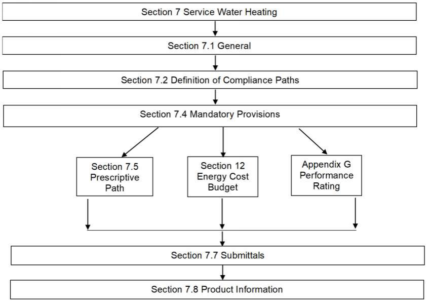
7. SERVICE WATER HEATING
7.1 General 7.1.1 Service Water-Heating Scope. Section 7 specifies requirements for service water-heating systems and equipment.
7.1.2 New Buildings. Service water-heating systems and equipment shall comply with the requirements of Section 7.2.
7.1.3 Additions to Existing Buildings. Service water-heating systems and equipment shall comply with the requirements of Section 7.2.
Exception to 7.1.3: When the service water heating to an addition is provided by existing service
water-heating systems and equipment, such systems and equipment shall not be required to comply with this standard. However, any new systems or equipment installed must comply with specific requirements applicable to those systems and equipment .
7.1.4 Alterations to Service Water-Heating Systems and Equipment. Building service water heating equipment installed as a direct replacement for existing building service water heating equipment shall comply with the requirements of Section 7 applicable to the equipment being replaced. New and replacement piping shall comply with Section 7.4.3.
Exception to 7.1.4: Compliance shall not be required where there is insufficient space or access to meet
these requirements.
7.2 Compliance Paths. Service water heating systems and equipment shall comply with Sections 7.2.1 and 7.2.2. 7.2.1 Requirements for All Compliance Paths. Service water heating systems and equipment shall comply with Sections 7.1, “General”; 7.4, “Mandatory Provisions”; 7.7, “Submittals”; and 7.8, “Product Information.”
7.2.2 Additional Requirements to Comply with Section 7. Service water heating systems and equip- ment shall comply with Section 7.5, “Prescriptive Compliance Path.”
7.3 Simplified Building Compliance Path (Not Used)
7.4 Mandatory Provisions 7.4.1 Load Calculations. Service water heating system design loads for the purpose of sizing systems and equipment shall be determined in accordance with the manufacturer ’s published sizing guidelines or
ANSI/ASHRAE/IES Standard 90.1-2022 (I-P) 137
PDF Page 140
generally accepted engineering standards and handbooks acceptable to the adopting authority (e.g., ASHRAE Handbook—HVAC Applications ).
7.4.2 Equipment Efficiency. All water-heating equipment, hot-water supply boilers used solely for heating potable water, pool heaters, and hot-water storage tanks shall meet the criteria listed in Table 7.4-1. Where multiple criteria are listed, all criteria shall be met. Omission of minimum performance requirements for certain classes of equipment does not preclude use of such equipment where appropriate. Equipment not listed in Table 7.4-1 has no minimum performance requirements.
Exceptions to 7.4.2: All water heaters and hot-water supply boilers having more than 140 gal of storage
capacity are not required to meet the standby loss (SL) requirements of Table 7.4-1 when
- the tank surface is thermally insulated to R-12.5,
- a standing pilot light is not installed, and
- gas- or oil-fired storage water heaters have a flue damper or fan-assisted combustion.
7.4.3 Service Water Heating System Piping Insulation. Service water heating system piping shall be surrounded by uncompressed insulation of the thickness shown in Table 7.4-2. When the insulation thermal conductivity is not within the range in the table, the following equation shall be used to calculate the minimum insulation thickness:
talt = r [(1 + ttable / r ) × kalt / kupper - 1]
where talt = minimum insulation thickness of the alternate material, in. r = actual outside radius of pipe, in. ttable = insulation thickness listed in Table 7.4-2 for applicable fluid temperature and pipe size kalt = thermal conductivity of the alternate material at mean rating temperature indicated for the applicable fluid temperature, Btu·in/h·ft [2] ·°F kupper = upper value of the thermal conductivity range listed in this table for the applicable fluid temperature, Btu·in/h·ft [2] ·°F Exception to 7.4.3: For nonmetallic piping thicker than Schedule 80 and having thermal resistance
greater than that of steel pipe, reduced insulation thicknesses are permitted if documentation is provided showing that the pipe with the proposed insulation has no more heat transfer per foot than a steel pipe of the same size with the insulation thickness shown in the table.
7.4.3.1 The following piping shall be insulated per the requirements of this section:
a. Recirculating system piping, including the supply and return piping b. The first 8 ft of outlet piping from
- storage water heaters,
- hot-water storage tanks, and
- any water heater and hot-water supply boiler containing 10 gal or more of water heated by a direct heat source, an indirect heat source, or both a direct heat source and an indirect heat source. c. The first 8 ft of branch piping connecting to recirculated, heat traced, or impedance heated piping. d. The make-up water inlet piping between heat traps (see Section 7.4.6) and the storage water heaters and
the storage tank they are serving, in a nonrecirculating service water heating system . e. Hot-water piping between multiple water heaters, between multiple hot-water storage tanks, and
between water heaters and hot-water storage tanks. f. Piping that is externally heated (such as heat trace or impedance heating).
Exceptions to 7.4.3.1:
- Factory-installed piping within water heaters and hot-water storage tanks tested and rated in accordance with Section 6.4.1.
- Piping that conveys hot water that has not been heated through the use of fossil fuels or electricity.
- For piping 1 in. or less, insulation is not required for valves or strainers.
- Piping in existing buildings where alterations are made to existing service water heating systems where there is insufficient space or access to meet the requirements.
- Insulation is not required at the point where piping passes through a framing member if it requires increasing the size of the framing member.
- Insulation is not required on piping at the point where a vertical support of the piping is installed.
138 ANSI/ASHRAE/IES Standard 90.1-2022 (I-P)
PDF Page 141
Table 7.4-1 Performance Requirements for Water-Heating Equipment—Minimum Efficiency Requirements
| Equipment Type | Size Category (Input) | Subcategory or Rating Condition | Performance Required a | Test Procedureb,c |
|---|---|---|---|---|
| Electric table-top water heaters | 12_kW_ | <4000 (Btu/h)/gal 20 gal and120 gal | For applications outside U.S., see footnote (h). For U.S. applications, see footnote (g). | 10 CFR 430 Appendix E |
| Electric storage water heaters | 12_kW_ | <4000 (Btu/h)/gal 20 gal and55 gal | For applications outside U.S., see footnote (h). For U.S. applications, see footnote (g). | 10 CFR 430 Appendix E |
| Electric storage water heaters | 12_kW_ | <4000 (Btu/h)/gal >55 gal and120 gal | For applications outside U.S., see footnote (h). For U.S. applications, see footnote (g). | 10 CFR 430 Appendix E |
| Electric storage water heaters | >12_kW_ | <4000 (Btu/h)/gal | SL 0.3 + 27/Vm %/h | 10 CFR 431.106 |
| Electric instantaneous_water_ heaters | 12_kW_ | 4000 (Btu/h)/gal <2 gal | For applications outside US, see footnote (h). For US applications, see footnote (g). | 10 CFR 430 Appendix E |
| Electric instantaneous_water_ heaters | >12_kW_ and 58.6_kW_ c | 4000 (Btu/h)/gal 2 gal 180°F | Very small DP: UEF = 0.80 Low DP: UEF = 0.80 Medium DP: UEF = 0.80 High DP: UEF = 0.80 | 10 CFR 430 Appendix E |
| Electric instantaneous_water_ heaters | 58.6_kW_ c | 4000 (Btu/h)/gal <10 gal | No requirement | No requirement |
| Electric instantaneous_water_ heaters | 58.6_kW_ c | 4000 (Btu/h)/gal 10 gal | No requirement | No requirement |
| Gas storage water heaters | 75,000 Btu/h | <4000 (Btu/h)/gal 20 gal and55 gal | For applications outside U.S., see footnote (h). For U.S. applications, see footnote (g). | 10 CFR 430 Appendix E |
| Gas storage water heaters | 75,000 Btu/h | <4000 (Btu/h)/gal >55 gal and100 gal | For applications outside U.S., see footnote (h). For U.S. applications, see footnote (g). | 10 CFR 430 Appendix E |
| Gas storage water heaters | >75,000 Btu/h and 105,000 Btu/h d | <4000 (Btu/h)/gal 120 gal 180°F | Very small DP: UEF = 0.2674 – (0.0009 ×Vr) Low DP: UEF = 0.5362 – (0.0012 ×Vr) Medium DP: UEF = 0.6002 – (0.0011 ×Vr) High DP: UEF = 0.6597 – (0.0009 ×Vr) | 10 CFR 430 Appendix E |
| Gas storage water heaters | >105,000 Btu/h d,f | <4000 (Btu/h)/gal | 80%_Et _ SL(Q/800 + 110 ), Btu/h V | 10 CFR 431.106 |
| Gas instantaneous water heaters | >50,000 Btu/h and 200,000 Btu/h | 4000 (Btu/h)/gal <2 gal | For applications outside U.S., see footnote (h). For U.S. applications, see footnote (g). | 10 CFR 430 Appendix E |
| Gas instantaneous water heaters | 200,000 Btu/h d,f | 4000 (Btu/h)/gal <10 gal | 80%Et | 10 CFR 431.106 |
| Gas instantaneous water heaters | 200,000 Btu/h f | 4000 (Btu/h)/gal 10 gal | 80%Et SL(Q/800 + 110 ), Btu/h V | 80%Et SL(Q/800 + 110 ), Btu/h V |
| a. Thermal_efficiency_ (Et) is a minimum requirement, while standby loss is a maximum requirement. In the standby loss equation,V is the rated volume in gallons and_Q_ is the name- plate input rate in Btu/h.Vm is the measured volume in the tank in gallons. Standby loss for electric water heaters is in terms of %/h and denoted by the term “S,” and standby loss for gas and oil water heaters is in terms of Btu/h and denoted by the term “SL.” Draw pattern (DP) refers to the water draw profile in the uniform_energy factor_ (UEF) test. UEF and_energy factor_ (EF) are minimum requirements. In the UEF standard equations,Vr refers to the rated volume in gallons. b. Section 13 contains a complete specification, including the year version, of the referenced test procedure. c. Electric instantaneous water heaters with input capacity >12 kW and58.6 kW must comply with the requirements for the 58.6 kW if the water heater either (1) has a storage volume >2 gal; (2) is designed to provide outlet hot water at temperatures greater than 180°F; or (3) uses three-phase power. d. Gas storage water heaters with input capacity >75,000 Btu/h and105,000 Btu/h must comply with the requirements for the >105,000 Btu/h if the water heater either (1) has a storage volume >120 gal; (2) is designed to provide outlet hot water at temperatures greater than 180°F; or (3) uses three-phase power e. Oil storage water heaters with input capacity >105,000 Btu/h and140,000 Btu/h must comply with the requirements for the >140,000 Btu/h if the water heater either (1) has a storage volume >120 gal; (2) is designed to provide outlet hot water at temperatures greater than 180°F; or (3) uses three-phase power f. Refer to Section 7.5.3 for additional requirements for gas storage and instantaneous_water heaters_ and gas_hot-water supply boilers_. g. Water heaters or gas_pool_ heaters in this category or subcategory are regulated as consumer products by the U.S. DOE as defined in 10 CFR 430. h. Where this standard is being applied to a building outside the U.S. and Canada and water heaters in this subcategory are being installed in that building, those water heaters shall meet the local efficiency requirements. If there are no local efficiency standards for residential water heaters, consideration should be given to using the U.S. DOE efficiency require- ments shown in Informative Appendix F, Table F-2. | a. Thermal_efficiency_ (Et) is a minimum requirement, while standby loss is a maximum requirement. In the standby loss equation,V is the rated volume in gallons and_Q_ is the name- plate input rate in Btu/h.Vm is the measured volume in the tank in gallons. Standby loss for electric water heaters is in terms of %/h and denoted by the term “S,” and standby loss for gas and oil water heaters is in terms of Btu/h and denoted by the term “SL.” Draw pattern (DP) refers to the water draw profile in the uniform_energy factor_ (UEF) test. UEF and_energy factor_ (EF) are minimum requirements. In the UEF standard equations,Vr refers to the rated volume in gallons. b. Section 13 contains a complete specification, including the year version, of the referenced test procedure. c. Electric instantaneous water heaters with input capacity >12 kW and58.6 kW must comply with the requirements for the 58.6 kW if the water heater either (1) has a storage volume >2 gal; (2) is designed to provide outlet hot water at temperatures greater than 180°F; or (3) uses three-phase power. d. Gas storage water heaters with input capacity >75,000 Btu/h and105,000 Btu/h must comply with the requirements for the >105,000 Btu/h if the water heater either (1) has a storage volume >120 gal; (2) is designed to provide outlet hot water at temperatures greater than 180°F; or (3) uses three-phase power e. Oil storage water heaters with input capacity >105,000 Btu/h and140,000 Btu/h must comply with the requirements for the >140,000 Btu/h if the water heater either (1) has a storage volume >120 gal; (2) is designed to provide outlet hot water at temperatures greater than 180°F; or (3) uses three-phase power f. Refer to Section 7.5.3 for additional requirements for gas storage and instantaneous_water heaters_ and gas_hot-water supply boilers_. g. Water heaters or gas_pool_ heaters in this category or subcategory are regulated as consumer products by the U.S. DOE as defined in 10 CFR 430. h. Where this standard is being applied to a building outside the U.S. and Canada and water heaters in this subcategory are being installed in that building, those water heaters shall meet the local efficiency requirements. If there are no local efficiency standards for residential water heaters, consideration should be given to using the U.S. DOE efficiency require- ments shown in Informative Appendix F, Table F-2. | a. Thermal_efficiency_ (Et) is a minimum requirement, while standby loss is a maximum requirement. In the standby loss equation,V is the rated volume in gallons and_Q_ is the name- plate input rate in Btu/h.Vm is the measured volume in the tank in gallons. Standby loss for electric water heaters is in terms of %/h and denoted by the term “S,” and standby loss for gas and oil water heaters is in terms of Btu/h and denoted by the term “SL.” Draw pattern (DP) refers to the water draw profile in the uniform_energy factor_ (UEF) test. UEF and_energy factor_ (EF) are minimum requirements. In the UEF standard equations,Vr refers to the rated volume in gallons. b. Section 13 contains a complete specification, including the year version, of the referenced test procedure. c. Electric instantaneous water heaters with input capacity >12 kW and58.6 kW must comply with the requirements for the 58.6 kW if the water heater either (1) has a storage volume >2 gal; (2) is designed to provide outlet hot water at temperatures greater than 180°F; or (3) uses three-phase power. d. Gas storage water heaters with input capacity >75,000 Btu/h and105,000 Btu/h must comply with the requirements for the >105,000 Btu/h if the water heater either (1) has a storage volume >120 gal; (2) is designed to provide outlet hot water at temperatures greater than 180°F; or (3) uses three-phase power e. Oil storage water heaters with input capacity >105,000 Btu/h and140,000 Btu/h must comply with the requirements for the >140,000 Btu/h if the water heater either (1) has a storage volume >120 gal; (2) is designed to provide outlet hot water at temperatures greater than 180°F; or (3) uses three-phase power f. Refer to Section 7.5.3 for additional requirements for gas storage and instantaneous_water heaters_ and gas_hot-water supply boilers_. g. Water heaters or gas_pool_ heaters in this category or subcategory are regulated as consumer products by the U.S. DOE as defined in 10 CFR 430. h. Where this standard is being applied to a building outside the U.S. and Canada and water heaters in this subcategory are being installed in that building, those water heaters shall meet the local efficiency requirements. If there are no local efficiency standards for residential water heaters, consideration should be given to using the U.S. DOE efficiency require- ments shown in Informative Appendix F, Table F-2. | a. Thermal_efficiency_ (Et) is a minimum requirement, while standby loss is a maximum requirement. In the standby loss equation,V is the rated volume in gallons and_Q_ is the name- plate input rate in Btu/h.Vm is the measured volume in the tank in gallons. Standby loss for electric water heaters is in terms of %/h and denoted by the term “S,” and standby loss for gas and oil water heaters is in terms of Btu/h and denoted by the term “SL.” Draw pattern (DP) refers to the water draw profile in the uniform_energy factor_ (UEF) test. UEF and_energy factor_ (EF) are minimum requirements. In the UEF standard equations,Vr refers to the rated volume in gallons. b. Section 13 contains a complete specification, including the year version, of the referenced test procedure. c. Electric instantaneous water heaters with input capacity >12 kW and58.6 kW must comply with the requirements for the 58.6 kW if the water heater either (1) has a storage volume >2 gal; (2) is designed to provide outlet hot water at temperatures greater than 180°F; or (3) uses three-phase power. d. Gas storage water heaters with input capacity >75,000 Btu/h and105,000 Btu/h must comply with the requirements for the >105,000 Btu/h if the water heater either (1) has a storage volume >120 gal; (2) is designed to provide outlet hot water at temperatures greater than 180°F; or (3) uses three-phase power e. Oil storage water heaters with input capacity >105,000 Btu/h and140,000 Btu/h must comply with the requirements for the >140,000 Btu/h if the water heater either (1) has a storage volume >120 gal; (2) is designed to provide outlet hot water at temperatures greater than 180°F; or (3) uses three-phase power f. Refer to Section 7.5.3 for additional requirements for gas storage and instantaneous_water heaters_ and gas_hot-water supply boilers_. g. Water heaters or gas_pool_ heaters in this category or subcategory are regulated as consumer products by the U.S. DOE as defined in 10 CFR 430. h. Where this standard is being applied to a building outside the U.S. and Canada and water heaters in this subcategory are being installed in that building, those water heaters shall meet the local efficiency requirements. If there are no local efficiency standards for residential water heaters, consideration should be given to using the U.S. DOE efficiency require- ments shown in Informative Appendix F, Table F-2. | a. Thermal_efficiency_ (Et) is a minimum requirement, while standby loss is a maximum requirement. In the standby loss equation,V is the rated volume in gallons and_Q_ is the name- plate input rate in Btu/h.Vm is the measured volume in the tank in gallons. Standby loss for electric water heaters is in terms of %/h and denoted by the term “S,” and standby loss for gas and oil water heaters is in terms of Btu/h and denoted by the term “SL.” Draw pattern (DP) refers to the water draw profile in the uniform_energy factor_ (UEF) test. UEF and_energy factor_ (EF) are minimum requirements. In the UEF standard equations,Vr refers to the rated volume in gallons. b. Section 13 contains a complete specification, including the year version, of the referenced test procedure. c. Electric instantaneous water heaters with input capacity >12 kW and58.6 kW must comply with the requirements for the 58.6 kW if the water heater either (1) has a storage volume >2 gal; (2) is designed to provide outlet hot water at temperatures greater than 180°F; or (3) uses three-phase power. d. Gas storage water heaters with input capacity >75,000 Btu/h and105,000 Btu/h must comply with the requirements for the >105,000 Btu/h if the water heater either (1) has a storage volume >120 gal; (2) is designed to provide outlet hot water at temperatures greater than 180°F; or (3) uses three-phase power e. Oil storage water heaters with input capacity >105,000 Btu/h and140,000 Btu/h must comply with the requirements for the >140,000 Btu/h if the water heater either (1) has a storage volume >120 gal; (2) is designed to provide outlet hot water at temperatures greater than 180°F; or (3) uses three-phase power f. Refer to Section 7.5.3 for additional requirements for gas storage and instantaneous_water heaters_ and gas_hot-water supply boilers_. g. Water heaters or gas_pool_ heaters in this category or subcategory are regulated as consumer products by the U.S. DOE as defined in 10 CFR 430. h. Where this standard is being applied to a building outside the U.S. and Canada and water heaters in this subcategory are being installed in that building, those water heaters shall meet the local efficiency requirements. If there are no local efficiency standards for residential water heaters, consideration should be given to using the U.S. DOE efficiency require- ments shown in Informative Appendix F, Table F-2. |
ANSI/ASHRAE/IES Standard 90.1-2022 (I-P) 139
PDF Page 142
Table 7.4-1 Performance Requirements for Water-Heating Equipment—Minimum Efficiency Requirements (Continued)
| Equipment Type | Size Category (Input) | Subcategory or Rating Condition | Performance Required a | Test Procedureb,c |
|---|---|---|---|---|
| Oil storage water heaters | 105,000 Btu/h | <4000(Btu/h)/gal 50 gal | For applications outside U.S., see footnote (h). For U.S. applications, see footnote (g). | 10 CFR 430 Appendix E |
| Oil storage water heaters | 105,000 Btu/h and 140,000 Btu/h e | 120 gal <4000 (Btu/h)/gal 180°F | Very small DP: UEF = 0.2932 – (0.0015 ×Vr) Low DP: UEF = 0.5596 – (0.0018 ×Vr) Medium DP: UEF = 0.6194 – (0.0016 ×Vr) High DP: UEF = 0.6740 – (0.0013 ×Vr) | 10 CFR 430 Appendix E |
| Oil storage water heaters | >140,000 Btu/h | <4000 (Btu/h)/gal | 80%Et SL(Q/800 + 110 ), Btu/h V | 10 CFR 431.106 |
| Oil instantaneous water heaters | 210,000 Btu/h | 4000 (Btu/h)/gal <2 gal | 80%Et EF 0.59 – 0.0005 ×V | 10 CFR 430 Appendix E |
| Oil instantaneous water heaters | >210,000 Btu/h | 4000 (Btu/h)/gal <10 gal | 80%Et | 10 CFR 431.106 |
| Oil instantaneous water heaters | >210,000 Btu/h | 4000 (Btu/h)/gal 10 gal | 78%_Et _ SL(Q/800 + 110 ), Btu/h V | 78%_Et _ SL(Q/800 + 110 ), Btu/h V |
| Hot-water supply boilers, gas and oil f | 300,000 Btu/h and <12,500,000 Btu/h | 4000 (Btu/h)/gal <10 gal | 80%Et | 10 CFR 431.106 |
| Hot-water supply boilers, gas f | 300,000 Btu/h and <12,500,000 Btu/h | 4000 (Btu/h)/gal 10 gal | 80%Et SL(Q/800 + 110 ), Btu/h V | 10 CFR 431.106 |
| Hot-water supply boilers, oil | 300,000 Btu/h and <12,500,000 Btu/h | 4000 (Btu/h)/gal 10 gal | 78%Et SL(Q/800 + 110 ), Btu/h V | 10 CFR 431.106 |
| Pool heaters, gas | All | 82%Et for commercial_pool_ heaters and for applications outside U.S. For U.S. applications, see footnote (g). | 10 CFR 430 Appendix P | |
| Heat pump_pool_ heaters | All | 50°F db 44.2°F wb outdoor air 80.0°F entering water | 4.0_COP_ | 10 CFR 430 Appendix P |
| Unfired storage tanks | All | R-12.5 | (none) | |
| a. Thermal_efficiency_ (Et) is a minimum requirement, while standby loss is a maximum requirement. In the standby loss equation,V is the rated volume in gallons and_Q_ is the name- plate input rate in Btu/h.Vm is the measured volume in the tank in gallons. Standby loss for electric water heaters is in terms of %/h and denoted by the term “S,” and standby loss for gas and oil water heaters is in terms of Btu/h and denoted by the term “SL.” Draw pattern (DP) refers to the water draw profile in the uniform_energy factor_ (UEF) test. UEF and_energy factor_ (EF) are minimum requirements. In the UEF standard equations,Vr refers to the rated volume in gallons. b. Section 13 contains a complete specification, including the year version, of the referenced test procedure. c. Electric instantaneous water heaters with input capacity >12 kW and58.6 kW must comply with the requirements for the 58.6 kW if the water heater either (1) has a storage volume >2 gal; (2) is designed to provide outlet hot water at temperatures greater than 180°F; or (3) uses three-phase power. d. Gas storage water heaters with input capacity >75,000 Btu/h and105,000 Btu/h must comply with the requirements for the >105,000 Btu/h if the water heater either (1) has a storage volume >120 gal; (2) is designed to provide outlet hot water at temperatures greater than 180°F; or (3) uses three-phase power e. Oil storage water heaters with input capacity >105,000 Btu/h and140,000 Btu/h must comply with the requirements for the >140,000 Btu/h if the water heater either (1) has a storage volume >120 gal; (2) is designed to provide outlet hot water at temperatures greater than 180°F; or (3) uses three-phase power f. Refer to Section 7.5.3 for additional requirements for gas storage and instantaneous_water heaters_ and gas_hot-water supply boilers_. g. Water heaters or gas_pool_ heaters in this category or subcategory are regulated as consumer products by the U.S. DOE as defined in 10 CFR 430. h. Where this standard is being applied to a building outside the U.S. and Canada and water heaters in this subcategory are being installed in that building, those water heaters shall meet the local efficiency requirements. If there are no local efficiency standards for residential water heaters, consideration should be given to using the U.S. DOE efficiency require- ments shown in Informative Appendix F, Table F-2. | a. Thermal_efficiency_ (Et) is a minimum requirement, while standby loss is a maximum requirement. In the standby loss equation,V is the rated volume in gallons and_Q_ is the name- plate input rate in Btu/h.Vm is the measured volume in the tank in gallons. Standby loss for electric water heaters is in terms of %/h and denoted by the term “S,” and standby loss for gas and oil water heaters is in terms of Btu/h and denoted by the term “SL.” Draw pattern (DP) refers to the water draw profile in the uniform_energy factor_ (UEF) test. UEF and_energy factor_ (EF) are minimum requirements. In the UEF standard equations,Vr refers to the rated volume in gallons. b. Section 13 contains a complete specification, including the year version, of the referenced test procedure. c. Electric instantaneous water heaters with input capacity >12 kW and58.6 kW must comply with the requirements for the 58.6 kW if the water heater either (1) has a storage volume >2 gal; (2) is designed to provide outlet hot water at temperatures greater than 180°F; or (3) uses three-phase power. d. Gas storage water heaters with input capacity >75,000 Btu/h and105,000 Btu/h must comply with the requirements for the >105,000 Btu/h if the water heater either (1) has a storage volume >120 gal; (2) is designed to provide outlet hot water at temperatures greater than 180°F; or (3) uses three-phase power e. Oil storage water heaters with input capacity >105,000 Btu/h and140,000 Btu/h must comply with the requirements for the >140,000 Btu/h if the water heater either (1) has a storage volume >120 gal; (2) is designed to provide outlet hot water at temperatures greater than 180°F; or (3) uses three-phase power f. Refer to Section 7.5.3 for additional requirements for gas storage and instantaneous_water heaters_ and gas_hot-water supply boilers_. g. Water heaters or gas_pool_ heaters in this category or subcategory are regulated as consumer products by the U.S. DOE as defined in 10 CFR 430. h. Where this standard is being applied to a building outside the U.S. and Canada and water heaters in this subcategory are being installed in that building, those water heaters shall meet the local efficiency requirements. If there are no local efficiency standards for residential water heaters, consideration should be given to using the U.S. DOE efficiency require- ments shown in Informative Appendix F, Table F-2. | a. Thermal_efficiency_ (Et) is a minimum requirement, while standby loss is a maximum requirement. In the standby loss equation,V is the rated volume in gallons and_Q_ is the name- plate input rate in Btu/h.Vm is the measured volume in the tank in gallons. Standby loss for electric water heaters is in terms of %/h and denoted by the term “S,” and standby loss for gas and oil water heaters is in terms of Btu/h and denoted by the term “SL.” Draw pattern (DP) refers to the water draw profile in the uniform_energy factor_ (UEF) test. UEF and_energy factor_ (EF) are minimum requirements. In the UEF standard equations,Vr refers to the rated volume in gallons. b. Section 13 contains a complete specification, including the year version, of the referenced test procedure. c. Electric instantaneous water heaters with input capacity >12 kW and58.6 kW must comply with the requirements for the 58.6 kW if the water heater either (1) has a storage volume >2 gal; (2) is designed to provide outlet hot water at temperatures greater than 180°F; or (3) uses three-phase power. d. Gas storage water heaters with input capacity >75,000 Btu/h and105,000 Btu/h must comply with the requirements for the >105,000 Btu/h if the water heater either (1) has a storage volume >120 gal; (2) is designed to provide outlet hot water at temperatures greater than 180°F; or (3) uses three-phase power e. Oil storage water heaters with input capacity >105,000 Btu/h and140,000 Btu/h must comply with the requirements for the >140,000 Btu/h if the water heater either (1) has a storage volume >120 gal; (2) is designed to provide outlet hot water at temperatures greater than 180°F; or (3) uses three-phase power f. Refer to Section 7.5.3 for additional requirements for gas storage and instantaneous_water heaters_ and gas_hot-water supply boilers_. g. Water heaters or gas_pool_ heaters in this category or subcategory are regulated as consumer products by the U.S. DOE as defined in 10 CFR 430. h. Where this standard is being applied to a building outside the U.S. and Canada and water heaters in this subcategory are being installed in that building, those water heaters shall meet the local efficiency requirements. If there are no local efficiency standards for residential water heaters, consideration should be given to using the U.S. DOE efficiency require- ments shown in Informative Appendix F, Table F-2. | a. Thermal_efficiency_ (Et) is a minimum requirement, while standby loss is a maximum requirement. In the standby loss equation,V is the rated volume in gallons and_Q_ is the name- plate input rate in Btu/h.Vm is the measured volume in the tank in gallons. Standby loss for electric water heaters is in terms of %/h and denoted by the term “S,” and standby loss for gas and oil water heaters is in terms of Btu/h and denoted by the term “SL.” Draw pattern (DP) refers to the water draw profile in the uniform_energy factor_ (UEF) test. UEF and_energy factor_ (EF) are minimum requirements. In the UEF standard equations,Vr refers to the rated volume in gallons. b. Section 13 contains a complete specification, including the year version, of the referenced test procedure. c. Electric instantaneous water heaters with input capacity >12 kW and58.6 kW must comply with the requirements for the 58.6 kW if the water heater either (1) has a storage volume >2 gal; (2) is designed to provide outlet hot water at temperatures greater than 180°F; or (3) uses three-phase power. d. Gas storage water heaters with input capacity >75,000 Btu/h and105,000 Btu/h must comply with the requirements for the >105,000 Btu/h if the water heater either (1) has a storage volume >120 gal; (2) is designed to provide outlet hot water at temperatures greater than 180°F; or (3) uses three-phase power e. Oil storage water heaters with input capacity >105,000 Btu/h and140,000 Btu/h must comply with the requirements for the >140,000 Btu/h if the water heater either (1) has a storage volume >120 gal; (2) is designed to provide outlet hot water at temperatures greater than 180°F; or (3) uses three-phase power f. Refer to Section 7.5.3 for additional requirements for gas storage and instantaneous_water heaters_ and gas_hot-water supply boilers_. g. Water heaters or gas_pool_ heaters in this category or subcategory are regulated as consumer products by the U.S. DOE as defined in 10 CFR 430. h. Where this standard is being applied to a building outside the U.S. and Canada and water heaters in this subcategory are being installed in that building, those water heaters shall meet the local efficiency requirements. If there are no local efficiency standards for residential water heaters, consideration should be given to using the U.S. DOE efficiency require- ments shown in Informative Appendix F, Table F-2. | a. Thermal_efficiency_ (Et) is a minimum requirement, while standby loss is a maximum requirement. In the standby loss equation,V is the rated volume in gallons and_Q_ is the name- plate input rate in Btu/h.Vm is the measured volume in the tank in gallons. Standby loss for electric water heaters is in terms of %/h and denoted by the term “S,” and standby loss for gas and oil water heaters is in terms of Btu/h and denoted by the term “SL.” Draw pattern (DP) refers to the water draw profile in the uniform_energy factor_ (UEF) test. UEF and_energy factor_ (EF) are minimum requirements. In the UEF standard equations,Vr refers to the rated volume in gallons. b. Section 13 contains a complete specification, including the year version, of the referenced test procedure. c. Electric instantaneous water heaters with input capacity >12 kW and58.6 kW must comply with the requirements for the 58.6 kW if the water heater either (1) has a storage volume >2 gal; (2) is designed to provide outlet hot water at temperatures greater than 180°F; or (3) uses three-phase power. d. Gas storage water heaters with input capacity >75,000 Btu/h and105,000 Btu/h must comply with the requirements for the >105,000 Btu/h if the water heater either (1) has a storage volume >120 gal; (2) is designed to provide outlet hot water at temperatures greater than 180°F; or (3) uses three-phase power e. Oil storage water heaters with input capacity >105,000 Btu/h and140,000 Btu/h must comply with the requirements for the >140,000 Btu/h if the water heater either (1) has a storage volume >120 gal; (2) is designed to provide outlet hot water at temperatures greater than 180°F; or (3) uses three-phase power f. Refer to Section 7.5.3 for additional requirements for gas storage and instantaneous_water heaters_ and gas_hot-water supply boilers_. g. Water heaters or gas_pool_ heaters in this category or subcategory are regulated as consumer products by the U.S. DOE as defined in 10 CFR 430. h. Where this standard is being applied to a building outside the U.S. and Canada and water heaters in this subcategory are being installed in that building, those water heaters shall meet the local efficiency requirements. If there are no local efficiency standards for residential water heaters, consideration should be given to using the U.S. DOE efficiency require- ments shown in Informative Appendix F, Table F-2. |
140 ANSI/ASHRAE/IES Standard 90.1-2022 (I-P)
PDF Page 143
Table 7.4-2 Minimum Piping Insulation Thickness for Service Water Heating Systems [ a,b]
| Service Hot-Water Temperature Range | Insulation Thermal Conductivity | Col3 | Nominal Pipe or Tube Size, in. | Col5 | Col6 | Col7 | Col8 |
|---|---|---|---|---|---|---|---|
| Service Hot-Water Temperature Range | Conductivity, Btu·in/h·ft2·°F | Mean Rating Temperature, °F | <1 | 1 to <1-1/2 | 1-1/2 to <4 | 4 to <8 | ≥8 |
| Service Hot-Water Temperature Range | Conductivity, Btu·in/h·ft2·°F | Mean Rating Temperature, °F | Insulation Thickness, in. | Insulation Thickness, in. | Insulation Thickness, in. | Insulation Thickness, in. | Insulation Thickness, in. |
Service Water Heating System Piping not Located in Partitions within Conditioned Spaces
| 105°F to 140°F | 0.22 to 0.28 | 100 | 1.0 | 1.0 | 1.5 | 2.0 | 2.0 |
|---|---|---|---|---|---|---|---|
| >140°F to 200°F | 0.25 to 0.29 | 125 | 1.5 | 1.5 | 2.5 | 2.5 | 2.5 |
| >200°F | 0.27 to 0.30 | 150 | 2.5 | 2.5 | 3.0 | 3.0 | 3.0 |
Service Water Heating System Piping Located in Partitions within Conditioned Spaces
| 105°F to 140°F | 0.22 to 0.28 | 100 | 1.0 | 1.0 | 1.5 | 1.5 | 1.5 |
|---|---|---|---|---|---|---|---|
| >140°F to 200°F | 0.25 to 0.29 | 125 | 1.0 | 1.0 | 2.0 | 2.0 | 2.0 |
| >200°F | 0.27 to 0.30 | 150 | 1.5 | 1.5 | 2.5 | 3.0 | 3.0 |
a. These thicknesses are based on energy efficiency considerations only. Additional insulation may be necessary for safety. b. For direct-buried service water heating system piping, reduction of these thicknesses by 1.5 in. shall be permitted (before thickness adjustment required in Section 7.4.3 but not
to thicknesses less than 1 in.).
7.4.4 Service Water-Heating System Controls Informative Note: Service water heating system control settings and operating temperatures should be determined in accordance with the ASHRAE Standard 188 building water systems water management program for the building, or with generally accepted engineering standards and guidance (e.g., ASHRAE Guideline 12).
7.4.4.1 Temperature Controls. Temperature controls shall be provided that allow for storage temperature adjustment from 120°F or lower to a maximum temperature compatible with the intended use.
Exception to 7.4.4.1: When the manufacturers ’ installation instructions specify a higher minimum ther-
mostat setting to minimize condensation and resulting corrosion.
7.4.4.2 Temperature Maintenance Controls. Systems designed to maintain usage temperatures in hotwater pipes, such as recirculating hot-water systems or heat trace, shall be equipped with automatic time switches or other controls that can be set to switch off the usage temperature maintenance system during extended periods when hot water is not required.
7.4.4.3 Outlet Temperature Controls. Temperature controlling means shall be provided to limit the maximum temperature of water delivered from lavatory faucets in public facility restrooms to 110°F.
7.4.4.4 Circulating Pump Controls. When used to maintain storage tank water temperature, recirculating pumps shall be equipped with controls limiting operation to a period from the start of the heating cycle to a maximum of five minutes after the end of the heating cycle.
7.4.5 Pools 7.4.5.1 Pool Heaters. Pool heaters shall be equipped with a readily accessible on/off switch to allow shutting off the heater without adjusting the thermostat setting. Pool heaters fired by natural gas shall not have continuously burning pilot lights.
7.4.5.2 Pool Covers. Heated pools shall be equipped with a vapor retardant pool cover on or at the water surface. Pools heated to more than 90°F shall have a pool cover with a minimum insulation value of R-12.
Exception to 7.4.5.2: Pools deriving over 60% of the energy for heating from site-recovered energy or
on-site renewable energy .
7.4.5.3 Time Switches. Time switches shall be installed on swimming pool heaters and pumps . Exceptions to 7.4.5.3:
- Where public health standards require 24-hour pump operation.
- Where pumps are required to operate solar and waste heat recovery pool heating systems.
7.4.6 Heat Traps. Vertical pipe risers serving storage water heaters and storage tanks not having integral heat traps and serving a nonrecirculating system shall have heat traps on both the inlet and outlet piping as close as practical to the storage tank. A heat trap is a means to counteract the natural convection of heated water in a vertical pipe run. The means is either (a) a device specifically designed for the purpose or an
ANSI/ASHRAE/IES Standard 90.1-2022 (I-P) 141
PDF Page 144
arrangement of tubing that forms a loop of 360 degrees, or (b) piping that from the point of connection to the water heater (inlet or outlet) includes a length of piping directed downward before connection to the vertical piping of the supply water or hot-water distribution system, as applicable.
7.5 Prescriptive Compliance Path 7.5.1 Space Heating and Service Water Heating. The use of a gas-fired or oil-fired space -heating boiler system otherwise complying with Section 6 to provide the total space heating and service water heating for a building is allowed when one of the following conditions is met:
a. The single space -heating boiler, or the component of a modular or multiple boiler system that is heating
the service water, has a standby loss in Btu/h not exceeding
(13.3 pmd + 400)/ n where pmd is the probable maximum demand in gal/h determined in accordance with the procedures described in generally accepted engineering standards and handbooks, and n is the fraction of the year when the outdoor daily mean temperature is greater than 64.9°F.
The standby loss is to be determined for a test period of 24 hours duration while maintaining a boiler water temperature of at least 90°F above ambient, with an ambient temperature between 60°F and 90°F. For a boiler with a modulating burner, this test shall be conducted at the lowest input. b. It is demonstrated to the satisfaction of the authority having jurisdiction that the use of a single heat
source will consume less energy than separate units. c. The energy input of the combined boiler and water heater system is less than 150,000 Btu/h.
7.5.2 Service Water-Heating Equipment. Service water-heating equipment used to provide the additional function of space heating as part of a combination (integrated) system shall satisfy all stated requirements for the service water-heating equipment .
7.5.3 Large Service Water-Heating Systems. New buildings with service water-heating systems with a total installed input capacity of 1,000,000 Btu/h or greater, provided by high-capacity gas-fired service water-heating equipment, shall meet either or both of the following requirements:
a. Where a single unit of high-capacity gas-fired service water-heating equipment is installed, it shall have
a minimum thermal efficiency ( Et ) of 92%. b. Multiple units of high-capacity gas-fired service water-heating equipment connected to the same service
water-heating system shall have a total input capacity-weighted average thermal efficiency ( Et ) of at least 90%, and a minimum of 30% of the input of the high-capacity gas-fired service water-heating equipment in the service water heating-system shall have a thermal efficiency ( Et ) of at least 92%.
High-capacity gas-fired service water-heating equipment comprises gas-fired instantaneous water heat- ers with a rated input both greater than 200,000 Btu/h and not less than 4000 Btu/h per gallon of stored water, and gas-fired storage water heaters with a rated input both greater than 105,000 Btu/h and less than 4000 Btu/h per gallon of stored water. Exceptions to 7.5.3:
- Water heaters installed in individual dwelling units .
- Individual gas water heaters with input capacity not greater than 100,000 Btu/h.
7.6 Alternative Compliance Path (Not Used)
7.7 Submittals 7.7.1 General. Compliance documentation and supplemental information shall be submitted in accordance with Section 4.2.2 of this standard.
7.7.2 Permit Application Documentation (Not Used) 7.7.3 Completion Requirements 7.7.3.1 Record Documents. Construction documents shall require that, within 90 days after the date of building envelope acceptance, record documents be provided to the building owner or the designated representative of the building owner.
7.7.3.2 Manuals. Construction documents shall require that an operating manual and a maintenance manual be provided to the building owner, or the designated representative of the building owner, within 90 days after the date of system acceptance. These manuals shall be in accordance with industry-accepted standards and shall include, at a minimum, operation manuals and maintenance manuals for each component of the system requiring maintenance, except components not furnished as part of the project. Required routine maintenance actions shall be clearly identified.
142 ANSI/ASHRAE/IES Standard 90.1-2022 (I-P)
PDF Page 145
7.8 Product Information
7.9 Verification, Testing, and Commissioning 7.9.1 Verification and Testing. Service hot-water controls shall be verified and tested in accordance with this section and Section 4.2.5.1. Testing shall verify that systems and controls are configured and operating in accordance with applicable requirements of
a. service water heating system temperature controls (Sections 7.4.4.1 and 7.4.4.3), b. recirculation pump or heat trace controls (Section 7.4.4.2), or c. pool time switch controls (Section 7.4.5.3).
Verification and FPT documentation shall comply with Section 4.2.5.1.2. 7.9.2 Commissioning. The energy performance of the service water heating systems shall be commis- sioned in accordance with Section 4.2.5.2, and reporting shall comply with Section 4.2.5.2.2.
ANSI/ASHRAE/IES Standard 90.1-2022 (I-P) 143
PDF Page 146
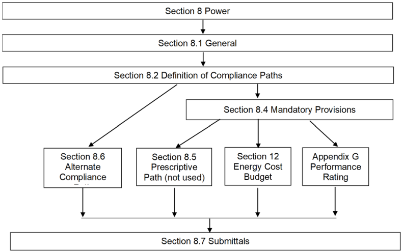
8. POWER
8.1 General
8.1.1 Scope. This section applies to all building power distribution systems and only to equipment described below.
8.1.2 New Building or Site System or Equipment. Building power distribution equipment installed shall comply with the requirements of Section 8.2.
8.1.3 Addition to Existing Systems and Equipment. Building power distribution equipment installed in addition to existing buildings and existing sites shall comply with the requirements of Section 8.2.
8.1.4 Alterations to Existing Service Equipment or Systems
Exception to 8.1.4: Compliance shall not be required for the relocation or reuse of existing equipment at
the same site .
8.1.4.1 Alterations to building service equipment shall comply with the requirements of Section 8, as applicable to those specific portions of the building that are being altered.
8.1.4.2 Alterations to systems shall comply with the requirements of Section 8, as applicable to those specific portions that are being altered.
8.1.4.3 Any new equipment subject to the requirements of Section 8 that is installed in conjunction with the alterations as a direct replacement of existing equipment shall comply with the specific requirements, as applicable to that equipment .
8.2 Compliance Paths. Power distribution systems and equipment shall comply with Sections 8.2.1 and 8.2.2.
8.2.1 Requirements for All Compliance Paths. Power distribution systems and equipment only shall comply with Sections 8.1, “General”; 8.4, “Mandatory Provisions”; and 8.7, “Submittals.”
Exception to 8.2.1: Power distribution systems and equipment only serving a computer room with IT
equipment load greater than 10 kW shall be permitted to comply with Section 8.6, “Alternative Compliance Path.”
8.2.2 Additional Requirements to Comply with Section 8 (Not Used)
8.3 Simplified Building Compliance Path (Not Used)
8.4 Mandatory Provisions
144 ANSI/ASHRAE/IES Standard 90.1-2022 (I-P)
PDF Page 147
8.4.1 Voltage Drop. The feeder conductors and branch circuits combined shall be sized for a maximum of 5% voltage drop total.
8.4.2 Automatic Receptacle Control. The following shall be automatically controlled:
a. At least 50% of all 125 V, 15 and 20 amp receptacles in all private offices, conference rooms, rooms used
primarily for printing and/or copying functions, break rooms, classrooms, and individual workstations. b. At least 25% of branch circuit feeders installed for modular furniture not shown on the construction doc-
uments.
This control shall function on
a. a scheduled basis using a time-of-day operated control device that turns receptacles off at specific pro grammed times—an independent program schedule shall be provided for controlled areas of no more than 5000 ft [2] and not more than one floor (the occupant shall be able to manually override the control device for up to two hours); b. an occupancy sensor that shall turn receptacles off within 20 minutes of all occupants leaving a space ; or c. an automated signal from another control or alarm system that shall turn receptacles off within 20 min utes after determining that the area is unoccupied.
All controlled receptacles shall be permanently marked to visually differentiate them from uncontrolled receptacles and are to be uniformly distributed throughout the space . Plug-in devices shall not be used to comply with Section 8.4.2.
Exceptions to 8.4.2: Receptacles for the following shall not require an automatic control device :
- Receptacles specifically designated for equipment requiring continuous operation (24/day, 365 days/year).
- Spaces where an automatic control would endanger the safety or security of the room or building occupants.
8.4.3 Electrical Energy Monitoring 8.4.3.1 Monitoring. Measurement devices shall be installed in new buildings to monitor the electrical energy use for each of the following separately:
a. Total electrical energy b. HVAC systems c. Interior lighting d. Exterior lighting e. Receptacle circuits f. Refrigeration systems
For buildings with tenants, these systems shall be separately monitored for the total building and (excluding shared systems ) for each individual tenant.
Exception to 8.4.3.1: Where the design load of any of the categories (b) through (f) are less than 10% of
the whole-building load, these categories shall be allowed to be combined with other categories.
8.4.3.2 Recording and Reporting. The electrical energy use for all loads specified in Section 8.4.3.1 shall be recorded a minimum of every 15 minutes and reported at least hourly, daily, monthly, and annually. The data for each tenant space shall be made available to that tenant. In buildings with a digital control sys- tem installed to comply with Section 6.4.3.10, the energy use data shall be transmitted to the digital control system and graphically displayed. The system shall be capable of maintaining all data collected for a minimum of 36 months.
Exceptions to 8.4.3.1 and 8.4.3.2:
- Building less than 25,000 ft [2] .
- Individual tenant spaces less than 10,000 ft [2] .
- Dwelling units .
- Residential buildings with less than 10,000 ft [2] of common area.
- Critical equipment and life-safety branches of NFPA 70, Article 517.
8.4.4 Low-Voltage Dry-Type Distribution Transformers. Low-voltage dry-type distribution transform- ers shall comply with the requirements shown in Table 8.4.4. Transformers that are not included in the definition of distribution transformers as defined in 10 CFR 431.192 have no performance requirements in this section and are listed for ease of reference as exceptions.
Exception to 8.4.4: Transformers that meet any of the following exclusions in the U.S. DOE definition of
“distribution transformers” found in 10 CFR 431.192:
ANSI/ASHRAE/IES Standard 90.1-2022 (I-P) 145
PDF Page 148
Table 8.4.4 Minimum Nominal Efficiency Levels for Low-Voltage Dry-Type Distribution Transformers [ a,b]
| Single-Phase Transformers | Col2 | Three-Phase Transformers | Col4 |
|---|---|---|---|
| kVA c | Efficiency,% d | kVA c | Efficiency,% d |
| 15 | 97.70 | 15 | 97.89 |
| 25 | 98.00 | 30 | 98.23 |
| 37.5 | 98.20 | 45 | 98.40 |
| 50 | 98.30 | 75 | 98.60 |
| 75 | 98.50 | 112.5 | 98.74 |
| 100 | 98.60 | 150 | 98.83 |
| 167 | 98.70 | 225 | 98.94 |
| 250 | 98.80 | 300 | 99.02 |
| 333 | 98.90 | 500 | 99.14 |
| 750 | 99.23 | ||
| 1000 | 99.28 |
a. A low-voltage dry-type distribution transformer is a transformer that is air-cooled, does not use oil as a coolant, has an input voltage 600 V, and is rated
for operation at a frequency of 60 Hz. b. A low-voltage dry-type distribution transformer with a kVA rating not listed in the table shall have its minimum efficiency level determined by linear
interpolation of the kVA and efficiency values listed in the table immediately above and below its kVA rating. Extrapolation shall not be used below the minimum values or above the maximum values shown for single-phase transformers and three-phase transformers . b. Kilovolt-ampere rating. c. Nominal efficiencies shall be established in accordance with the 10 CFR 431.193 test procedure for low-voltage dry-type distribution transformers .
- Transformers with tap range of 20% or more.
- Drive (isolation) transformer .
- Rectifier transformer .
- Auto- transformer .
- Uninterruptible power supply transformer .
- Special impedance transformer .
- Regulating transformer .
- Sealed and nonventilating transformer .
- Machine-tool (control) transformer .
- Welding transformer .
- Grounding transformer .
- Testing transformer .
- Nonventilated transformer.
8.5 Prescriptive Path (Not Used)
8.6 Alternative Compliance Path 8.6.1 Computer Room Systems. Power distribution systems and equipment only serving a computer room with IT equipment load greater than 10 kW shall comply with ASHRAE Standard 90.4, Energy Stan- dard for Data Centers.
8.7 Submittals 8.7.1 General. Compliance documentation and supplemental information shall be submitted in accordance with Section 4.2.2 of this standard.
8.7.2 Permit Application Documentation (Not Used) 8.7.3 Completion Requirements 8.7.3.1 Record Documents. Construction documents shall require that within 90 days after the date of system acceptance, record documents shall be provided to the property owner, including
a. a single-line diagram of the property electrical distribution system, b. floor plans indicating location and area served for all distribution, and c. site plans indicating location and area served for all distribution.
146 ANSI/ASHRAE/IES Standard 90.1-2022 (I-P)
PDF Page 149
8.7.3.2 Manuals. Construction documents shall require that an operating manual and maintenance manual be provided to the property owner. The manuals shall include, at a minimum, the following:
a. Submittal data stating equipment rating and selected options for each piece of equipment requiring main tenance. b. Operation manuals and maintenance manuals for each piece of equipment requiring maintenance.
Required routine maintenance actions shall be clearly identified. c. Names and addresses of at least one qualified service agency . d. A complete narrative of how each system is intended to operate.
Enforcement agencies should only check to ensure that the construction documents require this information to be transmitted to the owner and should not expect copies of any of the materials.
8.8 Product Information (Not Used)
8.9 Verification, Testing, and Commissioning 8.9.1 Verification and Testing. Building power distribution systems and applicable equipment shall be verified and tested in accordance with this section and provisions of Section 4.2.5.1. Testing shall verify that control elements are configured and operating in accordance with applicable requirements of
a. automatic receptacles controls (Section 8.4.2) and b. energy monitoring (Section 8.4.3).
Verification and FPT documentation shall comply with Section 4.2.5.1. 8.9.2 Commissioning. The energy performance of the power systems shall be commissioned in accordance with Section 4.2.5.2, and reporting shall comply with Section 4.2.5.2.2.
ANSI/ASHRAE/IES Standard 90.1-2022 (I-P) 147
PDF Page 150
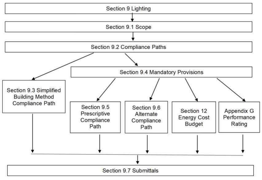
9. LIGHTING
9.1 General 9.1.1 Scope 9.1.1.1 New Building or Site System or Equipment. Lighting equipment and systems serving the lighting needs of new buildings or new site systems and equipment shall comply with the requirements of this section as described in Section 9.2.
This section shall apply to the following:
a. Lighting equipment and systems serving interior spaces of buildings . b. Lighting equipment and systems serving exterior applications.
Exceptions to 9.1.1.1:
- Emergency lighting that is automatically off during normal operation.
- Lighting, including exit signs, that is specifically designated as required by a health or life safety statute, ordinance, or regulation.
- Decorative gas lighting systems . 9.1.1.2 Additions to Existing Systems and Equipment. Lighting equipment and systems installed in addition to existing buildings and existing sites shall comply with the requirements of Section 9.1.1.1.
9.1.1.3 Alterations to Existing Systems and Equipment. The alteration of lighting equipment and sys- tems in an interior space shall comply with Section 9.1.1.3.1. The alteration of a lighting system in an exterior application shall comply with Section 9.1.1.3.2.
The maintenance of an existing lighting system to return it to working order shall not be considered an alteration . Retrofitting a luminaire for which the original lamps and ballast/driver are replaced with a new lamp/light source and driver / ballast that was not a component of the original luminaire shall be considered an alteration .
9.1.1.3.1 Alterations for Interior Building Spaces. The alteration of a lighting system in an interior space shall meet one of the following requirements:
a. The alteration shall comply with Section 9.2 when the total wattage of all new and retrofitted luminaires
is greater than 2000 W. b. When the total wattage of all new and retrofitted luminaires is 2000 W or less, each altered space shall
comply with the LPA of Tables 9.5.2.1-1 and 9.5.2.1-2 and Section 9.5.2.2, or the alteration shall result
148 ANSI/ASHRAE/IES Standard 90.1-2022 (I-P)
PDF Page 151
in a new wattage at least 50% below the original wattage of each altered lighting system . Additionally, the new and retrofitted lighting shall comply with the control requirements of Sections 9.4.1.1(a), 9.4.1.1(h), 9.4.1.1(i) as applicable to each altered space as shown in Tables 9.5.2.1-1 and 9.5.2.1-2 and Section 9.5.2.2.
9.1.1.3.2 Lighting Alterations for Exterior Building Areas. The alteration of a lighting system for an exterior area shall use only the area-specific allowances in Table 9.4.2-2 and shall not use the base site allowances to determine the LPA . Additionally, the exterior alteration shall meet one of the following:
a. The alteration shall comply with Section 9.2 when the total number of new and retrofitted luminaires is
greater than 10 or where the combined length of new and retrofitted linear luminaires is greater than 20 linear feet. b. Where the total number of new and retrofitted luminaires is not greater than 10, or where the combined
length of new and retrofitted linear luminaires is not greater than 20 linear feet of linear luminaires, the total wattage of the alteration shall be no greater than the maximum LPA permitted by Table 9.4.2-2, or the total new wattage shall be at least 50% below the total original wattage of that lighting system . Additionally, the new and retrofitted lighting shall comply with the control requirements of Section 9.4.1.4(a).
9.1.2 Climate. Climate zones shall be determined in accordance with Section 5.1.5. 9.1.3 Installed Lighting Power. The luminaire wattage for all interior and exterior applications shall include all power used by the luminaires, including lamps, ballasts / drivers, transformers, and control devices, except as specifically exempted in Section 9.1.1, 9.2.2.1, or 9.2.2.2.
Exception to 9.1.3: If two or more independently operating lighting systems in a space are capable of
being controlled to prevent simultaneous user operation, the installed interior lighting power or the installed exterior lighting power shall be based solely on the lighting system with the highest wattage.
9.1.4 Interior and Exterior Luminaire Wattage. The wattage of lighting equipment, when used to calculate either installed interior lighting power or installed exterior lighting power, shall be determined in accordance with the following criteria:
a. The wattage of lighting equipment connected to line voltage shall be the manufacturers ’ labeled maxi mum wattage. b. The wattage of line voltage lighting equipment with remote ballasts / drivers or similar devices shall be
the total input wattage of all line voltage components in the system . Exception to 9.1.4(b): Lighting power calculations for ballasts with adjustable ballast factors shall be
based on the ballast factor that will be used in the space, provided that the ballast factor is not user field-changeable. c. The wattage of line-voltage lighting track and plug-in busway designed to allow the addition and/or relo cation of lighting equipment without altering the wiring of the system shall be the lesser of
- the specified wattage of the lighting equipment included in the system with a minimum of 10 W/lin ft or
- the wattage limit of permanent current-limiting devices on the system . d. The wattage of low-voltage lighting track, cable conductor, rail conductor, and other flexible lighting
systems that allow the addition and/or relocation of lighting equipment without altering the wiring of the system shall be the specified wattage of the ballast/driver or transformer supplying the system . e. The wattage of a DC low-voltage lighting system that employs flexible cabling for plug-in connection of
the lighting equipment and a remote power supply shall be labeled maximum wattage of the system power supply. For systems that also provide power to equipment other than lighting, the wattage shall be labeled maximum wattage of the system power supply reduced by the wattage of the nonlighting equip- ment connected to the system . f. The wattage of a retrofitted luminaire shall be the manufacturer’s labeled input power of the new light source plus driver. g. The wattage of all other miscellaneous lighting equipment shall be the specified wattage of the lighting
equipment .
9.2 Compliance Paths. Lighting systems and equipment shall comply with Section 9.2.1. 9.2.1 Requirements for All Compliance Paths. Lighting systems and equipment shall comply with Sections 9.1 “General”; 9.7, “Submittals”; 9.9, “Verification, Testing, and Commissioning”; and one of the following:
a. Section 9.3, “Simplified Building Method Compliance Path” or b. Section 9.4, “Mandatory Provisions”, and Section 9.5.1, “Building Area Method Compliance Path” or
ANSI/ASHRAE/IES Standard 90.1-2022 (I-P) 149
PDF Page 152
c. Section 9.4, “Mandatory Provisions,” and Section 9.5.2, “Space-by-Space Method Compliance Path” or d. Section 9.4, “Mandatory Provisions,” and Section 9.6 “Alternative Compliance Path,” or e. Section 9.4, “Mandatory Provisions,” and Section 12, “Energy Cost Budget Method,” or f. Section 9.4, “Mandatory Provisions,” and Normative Appendix G, “Performance Rating Method.”
The installed lighting power identified in accordance with Section 9.1.3 shall not exceed the lighting power allowance developed in accordance with Section 9.2.1(a), (b), or (c).
9.2.2 Prescriptive Requirements 9.2.2.1 Interior Lighting Power Allowance. The interior lighting power allowance for a building or a separately metered or permitted portion of a building shall be determined by either Simplified Building Method described in Section 9.3, the Building Area Method described in Section 9.5.1, or the Space-by-Space Method described in Section 9.5.2.
Trade-offs of lighting power allowance among portions of the building for which a different calculation method has been used for compliance are not permitted.
Exception to 9.2.2.1: When using the compliance methods in Section 9.5.1 or 9.5.2 only, the lighting
equipment and applications listed in Table 9.2.2.1 shall not be considered when determining the inte- rior lighting power allowance developed in accordance with Section 9.5.1 or 9.5.2, nor shall the wattage for such lighting be included in the installed interior lighting power identified in accordance with Section 9.1.3. This exemption shall only apply when the lighting and controls are in compliance with the requirements of Table 9.2.2.1. Lighting controls noted in this table are the only required controls for this equipment and these applications.
9.2.2.2 Exterior Lighting Power Allowance. The exterior lighting power allowance shall be determined by
a. Section 9.3.2, “Simplified Building Method of Calculating Exterior Lighting Power Allowance,” when
using Section 9.3 to determine the interior lighting power allowance, or b. Section 9.4.2, “Exterior Lighting Power.”
9.3 Simplified Building Method Compliance Path. The Simplified Building Method contains the requirements for interior lighting in Section 9.3.1 and exterior lighting in Section 9.3.2 and shall be allowed to be used where at least 80% of the floor area supports either office buildings, retail buildings, or school buildings . The Simplified Building Method shall be used for new buildings or tenants improvements of less than 25,000 ft [2] . Interior and exterior wattage allowances shall be calculated and complied with separately.
9.3.1 Simplified Building Method of Calculating Interior Lighting Power Allowance. Buildings (new and alterations ) shall comply with the lighting power allowance and control requirements of Table 9.3.1-1, Table 9.3.1-2, or Table 9.3.1-3.
9.3.2 Simplified Building Method of Calculating Exterior Lighting Power Allowance. For all building types listed in Section 9.3, exterior areas (new and alterations ) shall comply with the lighting power allowance and control requirements of Table 9.3.2.
9.4 Mandatory Provisions 9.4.1 Lighting Control. Lighting controls shall be installed to meet the provisions of Section 9.4.1.1, 9.4.1.2, 9.4.1.3, and 9.4.1.4. 9.4.1.1 Interior Lighting Controls. For each space in the building, all of the lighting control functions indicated in Tables 9.5.2.1-1 and 9.5.2.1-2, for the appropriate space type in the first column, and as described below, shall be implemented. All control functions indicated as “REQ” are mandatory and shall be implemented. If a space type has control functions indicated as “ADD1,” then at least one of those functions shall be implemented. If a space type has control functions indicated as “ADD2,” then at least one of those functions shall be implemented. For space types not listed, select a reasonably equivalent type.
If using the Space-by-Space Method, the space type used for determining control requirements shall be the same space type that is used for determining the LPD allowance.
a. Local control: There shall be one or more manual lighting control device that provides ON and OFF control
of all lighting in the space . Each control device shall control an area (1) no larger than 2500 ft [2] if the space is 10,000 ft [2] and (2) no larger than 10,000 ft [2] otherwise. The device installed to comply with this provision shall be readily accessible and located so that the occupants can see the controlled lighting when using the control device . Exception to 9.4.1.1(a): Remote location of this local control device or devices shall be permitted for
reasons of safety or security when each remote control device has an indicator pilot light as part of or next to the control device and the control device is clearly labeled to identify the controlled lighting.
150 ANSI/ASHRAE/IES Standard 90.1-2022 (I-P)
PDF Page 153
Table 9.2.2.1 Exceptions to Interior Lighting Power and Minimum Control Requirements
| Item # | Equipment/Application | In Addition to and Controlled Separately from General Lighting | Required Controls |
|---|---|---|---|
| 1 | Lighting that is integral to_equipment_, medical_equipment_ or instrumentation, and is installed by its_manufacturer_ | YES | No control requirements |
| 2 | Power for only the germicidal function in_luminaires_ or sources | YES | No control requirements |
| 3 | Lighting specifically designed for use only during medical or dental procedures | YES | 9.4.1.1(a)—Local control |
| 4 | Lighting specifically designed for the research or support of nonhuman life forms except for horticultural production or cultivation | YES | 9.4.1.1(a)—Local control |
| 5 | Lighting for video broadcasting, video or film production, or live performance | YES | 9.4.1.1(a)—Local control |
| 6 | Lighting that is an integral part of advertising or directional signage | YES | 9.4.1.1(i)—Scheduled shutoff |
| 7 | Lighting integral to both open and glass-enclosed refrigerator and freezer cases | YES | 9.4.1.1(h)—Automatic fullOFF or 9.4.1.1(i)—Scheduled shutoff |
| 8 | Lighting in retail display windows, provided the display area is enclosed by ceiling-height partitions | YES | 9.4.1.1(a)—Local control and 9.4.1.1(i)—Scheduled shutoff |
| 9 | Display or accent lighting that is an essential element for the function performed in galleries, museums, and monuments | YES | 9.4.1.1(a)—Local control and either 9.4.1.1(h)—Automatic fullOFF or 9.4.1.1(i)—Scheduled shutoff |
| 10 | Lighting integral to food warming and food preparation equipment | YES | 9.4.1.1(a)—Local control and either 9.4.1.1(h)—Automatic fullOFF or 9.4.1.1(i)—Scheduled shutoff |
| 11 | Lighting that is for sale or lighting educational demonstration systems | YES | 9.4.1.1(a)—Local control and either 9.4.1.1(h)—Automatic fullOFF or 9.4.1.1(i)—Scheduled shutoff |
| 12 | Mirror lighting in makeup or dressing areas used for theatrical or broadcast functions | YES | 9.4.1.1(a)—Local control and either 9.4.1.1(h)—Automatic fullOFF or 9.4.1.1(i)—Scheduled shutoff |
| 13 | Accent lighting in religious pulpit and choir areas | YES | 9.4.1.1(a)—Local control and either 9.4.1.1(h)—Automatic fullOFF or 9.4.1.1(i)—Scheduled shutoff |
| 14 | Lighting in interior_spaces_ that have been specifically designated as a registered interior_historic_ landmark | NO | 9.4.1.1(a)—Local control and either 9.4.1.1(h)—Automatic fullOFF or 9.4.1.1(i)—Scheduled shutoff |
| 15 | Furniture-mounted supplemental_task lighting_ | YES | 9.4.1.1(a)—Local control and 9.4.1.1(h)—Automatic fullOFF |
ANSI/ASHRAE/IES Standard 90.1-2022 (I-P) 151
PDF Page 154
Table 9.2.2.2 Exceptions to Exterior Lighting Power and Minimum Control Zones
| Item # | Equipment/Application | Controlled Separately from General Lighting | Required Controls |
|---|---|---|---|
| 1 | Specialized signal, directional, and marker lighting associated with transportation | Yes | 9.4.1.4(a) |
| 2 | Lighting integral to_equipment_ or instrumentation and installed by its_manufacturer_ | Yes | 9.4.1.4(a) |
| 3 | Temporary lighting | Yes | 9.4.1.4(a) |
| 4 | Searchlights | Yes | 9.4.1.4(a) |
| 5 | Lighting for hazardous locations | Yes | 9.4.1.4(a) |
| 6 | Lighting integral to public art a | Yes | 9.4.1.4(a) |
| 7 | Lighting used to highlight features of public monuments, public art a displays, and registered_historic_ landmark_structure_ or_buildings_. | Yes | 9.4.1.4(b) |
| 8 | Lighting for theatrical purposes, including performance, stage, film production, and video production | Yes | 9.4.1.4(a) |
| 9 | Lighting for athletic playing areas for colleges and professional sports venues | Yes | 9.4.1.4(a) |
| 10 | Lighting for athletic playing areas | Yes | 9.4.1.4(a), (b), or (c) |
| 11 | Lighting for swimming_pools_ | Yes | 9.4.1.4(a) |
| 12 | Lighting for water features | Yes | 9.4.1.4(b) or (c) |
| 13 | Theme elements in theme/amusement parks | Yes | 9.4.1.4(c) |
| 14 | Lighting that is integral to signage and installed in the signage by the_manufacturer_ | Yes | 9.4.1.4(d) |
| 15 | Lighting for industrial production, material handling, transportation sites, and associated storage areas | Yes | 9.4.1.4(b), (d), or (e) |
a. Informative Note: “Public art” means art funded either with public or private funds but intended and accessible for the general public.
b. Restricted to manual ON: None of the lighting shall be automatically turned on.
Exception to 9.4.1.1(b): Manual ON is not required where manual ON operation of the general lighting
would endanger the safety or security of the room or building occupants. c. Restricted to partial automatic ON: No more than 50% of the lighting power for the general lighting shall
be allowed to be automatically turned on, and none of the remaining lighting shall be automatically turned on.
Offices greater than 300 ft [2], shall have the following requirements:
- Control zones for general lighting shall be limited to 600 ft [2] .
- Control zones for general lighting shall be permitted to automatically turn on, up to full power upon occupancy.
- General lighting in other unoccupied control zones shall be permitted to automatically turn on to no more than 20% of full power. d. Multilevel lighting control: The general lighting in the space shall be manually controlled with continu-
ous dimming to 10% or less of full lighting power in addition to full ON and full OFF. e. Automatic daylight responsive controls for sidelighting: In any space where the combined input power of
all general lighting completely or partially within the primary sidelighted areas is 75 W or greater, the gen- eral lighting in the primary sidelighted areas shall be controlled by photocontrols.
In any space where the combined input power of all general lighting completely or partially within the primary sidelighted area and secondary sidelighted area is 150 W or greater, the general lighting in the primary sidelighted area and secondary sidelighted area shall be controlled by photocontrols. Gen- eral lighting in the secondary sidelighted area shall be controlled independently of the general lighting in the primary sidelighted area .
The control system shall have the following characteristics:
- The calibration adjustment control shall be located no higher than 11 ft above the finished floor . Calibration shall not require the physical presence of a person at the sensor while it is processing.
152 ANSI/ASHRAE/IES Standard 90.1-2022 (I-P)
PDF Page 155
| Table 9.3.1-1 Simplified Building Method for Office Buildings | Col2 |
|---|---|
| Interior Space Type and LPA | Controls |
| All_spaces_ in office_buildings_ other than parking garages The total_LPA_for the_ building_other than parking garages shall not exceed 0.56 W/ft2. | All lighting shall be_automatically_controlled to turn off when individual_spaces_are either unoccupied or scheduled to be unoccupied. (Exception: Lighting load not exceeding 0.02 W/ft2 multiplied by the gross lighted area of the_space_ shall be permitted to operate at all times.) Each_space_ shall have a_manual control device_ that allows the occupant to reduce lighting power by a minimum of 50% and to turn the lighting off. |
| Office_spaces_ 150 ft2, classrooms, conference rooms, meeting rooms, training rooms, storage rooms, and break rooms | These_spaces_ shall also be controlled by_manual_-ON occupant sensors. |
| Office_spaces_ >150 ft2 and restrooms | These_spaces_ shall also be controlled by_occupant sensors_. |
| Stairwells and corridors in office_buildings_ | These_spaces_ shall also be controlled by_occupant sensors_ that reduce the lighting power by a minimum of 50% when no activity is detected for not longer than 15 minutes and be controlled to turn off when the_building_ is either unoccupied or scheduled to be unoccupied. |
| Parking garages: The_LPA_shall not exceed 0.14 W/ft2 for the interior parking floors. Uncovered floors of a garage shall use_LPA_and control requirements in Table 9.3.2 for parking lots. | All lighting shall be controlled by_occupant sensors_. Controls shall reduce the power by a minimum of 50% when no activity is detected for not longer than 15 minutes. No device shall_control_ more than 3600 ft2. |
| Table 9.3.1-2 Simplified Building Method for Retail Buildings | Col2 |
|---|---|
| Interior Space Type | Controls |
| All_spaces_ in retail_buildings_ other than parking garages The total_LPA_for the_building_other than parking garages shall not exceed 0.70 W/ft2. | All lighting shall be_automatically_controlled to turn off when individual_spaces_are either unoccupied or scheduled to be unoccupied. (Exception: Lighting load not exceeding 0.02 W/ft2 multiplied by the gross lighted area of the_space_ shall be permitted to operate at all times.) Each_space_ shall have a_manual_ control device that allows the occupant to reduce lighting power by a minimum of 50% and to turn the lighting off. |
| Sales area | These_spaces_ shall also be_automatically_controlled to • reduce the_general lighting_ power by a minimum of 75% during nonbusiness hours, • to turn off all lighting other than_general lighting_ during nonbusi- ness hours, and • by_continuous daylight dimming_ controls in_spaces_ with_toplighting_. |
| Stock rooms, dressing/fitting rooms, locker rooms, and restrooms | These_spaces_ shall also be controlled by; auto-ON or_manual_-ON occupant sensors, and_continuous daylight dimming_ controls in spaces with_toplighting_. |
| Office_spaces_, conference rooms, meeting rooms, training rooms, storage rooms, break rooms, and utility_spaces_ | These_spaces_ shall also be controlled by;manual-ON occupant sensors, and_continuous daylight dimming_ controls in_spaces_ with toplighting. |
| Stairwells and corridors in retail_buildings_ | These_spaces_ shall also be controlled by_occupant sensors_ that reduce the lighting power by a minimum of 50% when no activity is detected for not longer than 15 minutes and be controlled to turn off when the_building_is either unoccupied or scheduled to be unoccupied. |
| Parking garages: The_LPA_shall not exceed 0.14 W/ft2 for the interior parking floors. Uncovered floors of a garage shall use_LPA_and control requirements in Table 9.3.2 for parking lots. | All lighting shall be controlled by_occupant sensors_. Controls shall reduce the power by a minimum of 50% when no activity is detected for not longer than 15 minutes. No device shall_control_ a more than 3600 ft2. |
ANSI/ASHRAE/IES Standard 90.1-2022 (I-P) 153
PDF Page 156
Table 9.3.1-3 Simplified Building Method for School Buildings
| Interior Space Type | Controls |
|---|---|
| All_spaces_ in school_buildings_ other than parking garages The total_LPA_for the_building_other than parking garages shall not exceed 0.63 W/ft2 | All lighting shall be_automatically_controlled to turn off when individual_spaces_are either unoccupied or scheduled to be unoccupied. (Exception: Lighting load not exceeding 0.02 W/ft2 multiplied by the gross lighted area of the_space_ shall be permitted to operate at all times.) Each_space_ shall have a_manual_ control device that allows the occupant to reduce lighting power by a minimum of 50% and to turn the lighting off. |
| Classrooms, offices_spaces_, conference rooms, meeting rooms, library, storage rooms, and break rooms | These_spaces_ shall also be controlled by_manual_-ON occupant sensors. |
| Gymnasiums and cafeterias | These_spaces_ shall also be controlled by_occupant sensors_. |
| Restrooms | These_spaces_ shall also be controlled by_occupant sensors_. |
| Stairwells and corridors in school_buildings_ and parking garages | These_spaces_ shall also be controlled by_occupant sensors_ that reduce the lighting power by a minimum of 50% when no activity is detected for not longer than 15 minutes and be controlled to turn off when the _building_is either unoccupied or scheduled to be unoccupied. |
| Parking Garages: The_LPA_shall not exceed 0.14 W/ft2 for the interior parking floors. Uncovered floors of a garage shall use_LPA_and control requirements in Table 9.3.2 for parking lots. | All lighting shall be controlled by_occupant sensors_. Controls shall reduce the power by a minimum of 50% when no activity is detected for not longer than 15 minutes. No device shall_control_ a more than 3600 ft2. |
Table 9.3.2 Simplified Building Method for Building Exteriors
| Exterior Area Type | Exterior Lighting Power Allowance a,b | Controls |
|---|---|---|
| All exterior areas | All lighting shall be_automatically_controlled to shut off the lighting when daylight is available. | |
| Base allowance | 200 W | Luminaires shall be turned off or the power reduced by a minimum of 75% during nonoperating hours. |
| Façade lighting | 0.10 W/ft2 | Luminaires shall be turned off or the power reduced by a minimum of 75% during nonoperating hours. |
| Roof terraces, special feature areas, walkways, plazas and ramps | 0.07 W/ft2 | _Luminaires_shall be turned off or the power reduced by a minimum of 75% during nonoperating hours. |
| Landscape | 0.036 W/ft2 | Luminaires shall be turned off or the power reduced by a minimum of 75% during nonoperating hours. |
| Entry doors | 14 W/linear ft | Luminaires shall be turned off or the power reduced by a minimum of 75% during nonoperating hours. |
| Stairs | Exempt | No additional controls required. |
| Parking lots and drives | 0.037 W/ft2 | Luminaires mounted 25 ft or less above_grade_ shall be controlled to reduce the power by at least 50% when no activity is detected for not longer than 15 minutes. |
| All other areas not listed | 0.20 W/ft2 | Luminaires shall be turned off or the power reduced by a minimum of 75% during nonoperating hours. |
a. To calculate the exterior allowance, multiply the space or area square footage by the allowed W/ft [2] and sum the exterior allowances and the base allowance. Façade lighting shall
be calculated separately by multiplying the facade area by the allowed W/ft [2] . Façade allowance shall not be traded with other exterior areas or between separate facade areas . b. For buildings in Lighting Zone 2, as defined in Table 9.4.2-1, multiply exterior allowances by 0.7. For buildings in Lighting Zone 4, as defined in Table 9.4.2-1, multiply exterior
allowances by 1.4.
154 ANSI/ASHRAE/IES Standard 90.1-2022 (I-P)
PDF Page 157
-
The photocontrol shall reduce electric lighting power in response to available daylight using continu- ous daylight dimming to 20% or less and off.
-
When an automatic reduction control has reduced the lighting power to the unoccupied set point in accordance with Section 9.4.1.1(g), the daylight responsive control shall adjust the electric light in response to available daylight, but it shall not allow the lighting power to be above the unoccupied set point . Exceptions to 9.4.1.1(e): The following areas are exempted from Section 9.4.1.1(e):
-
Primary sidelighted areas where the top of any existing adjacent structure or natural object is at least twice as high above the windows as its horizontal distance away from the windows.
-
Sidelighted areas where the total glazing area is less than 20 ft [2] .
-
Primary sidelighted areas adjacent to vertical fenestration that have external projections and no vertical fenestration above the external projection, where the external projection has a projection factor greater than 1.0 for north-oriented projections or where the external projection has a pro- jection factor greater than 1.5 for all other orientations (see Figure 3.2-6). f. Automatic daylight responsive controls for toplighting : In any space where the combined input power for all general lighting completely or partially within daylight area under skylights and daylight area under roof monitors is 75 W or greater, general lighting in the daylight area shall be controlled by photocontrols. The control system shall have the following characteristics:
-
The calibration adjustment control shall be located no higher than 11 ft above the finished floor . Calibration shall not require the physical presence of a person at the sensor while it is processing.
-
The photocontrol shall reduce lighting power in response to available daylight using continuous day- light dimming to 20% or less and off.
-
When an automatic reduction control has reduced the lighting power to the unoccupied set point in accordance with Section 9.4.1.1(g) the daylight responsive control shall adjust the electric light in response to available daylight, but it shall not allow the lighting power to be above the unoccupied set point .
-
General lighting in overlapping toplighted and sidelighted daylight areas shall be controlled together with general lighting in the daylight area under skylights or daylight area under roof monitors . Exceptions to 9.4.1.1(f): The following areas are exempted from Section 9.4.1.1(f):
-
Daylight area under skylights where it is documented that existing adjacent structures or natural objects block direct sunlight for more than 1500 daytime hours per year between 8 a.m. and 4 p.m.
-
Daylight area under skylights where the overall skylight effective aperture for the enclosed space is less than 0.006.
-
In each space within buildings in Climate Zone 8 where the input power of the general lighting within daylight areas is less than 200 W. g. Automatic reduction control (full OFF complies): The general lighting power in the space shall be auto-
matically reduced by at least 50% within 20 minutes of all occupants leaving the space .
In offices greater than 300 ft [2], control zones for general lighting shall
- be limited to 600 ft [2] and
- automatically reduce general lighting by at least 80% of full power within 20 minutes of all occupants leaving a control zone. h. Automatic full OFF control: All lighting in the space, including lighting connected to emergency circuits,
shall be automatically shut off within 20 minutes of all occupants leaving the space . A control device meeting this requirement shall control no more than 5000 ft [2] . Exceptions to 9.4.1.1(h): The following lighting is not required to be automatically shut off:
- Lighting required for 24/7 continuous operation.
- Lighting in spaces where patient care is rendered.
- General lighting and task lighting in spaces where automatic shutoff would endanger the safety or security of the room or building occupants.
- Lighting load not exceeding 0.02 W/ft [2] multiplied by the gross lighted floor area of the building . i. Scheduled shutoff : All lighting in the space, including lighting connected to emergency circuits, shall be automatically shut off during periods when the space is scheduled to be unoccupied using either (1) a time-of-day operated control device that automatically turns the lighting off at specific programmed times or (2) a signal from another automatic control device or alarm/security system . The control device or system shall provide independent control sequences that (1) control the lighting for an area of no more than 25,000 ft [2], (2) include no more than one floor, and (3) shall be programmed to account for weekends and holidays. Any manual control installed to provide override of the scheduled shutoff control
ANSI/ASHRAE/IES Standard 90.1-2022 (I-P) 155
PDF Page 158
shall not turn the lighting on for more than two hours per activation during scheduled off periods and shall not control more than 5000 ft [2] . Exceptions to 9.4.1.1(i): The following lighting is not required to be on scheduled shutoff:
- Lighting required for 24/7 continuous operation.
- Lighting in spaces where patient care is rendered.
- General lighting and task lighting in spaces where automatic shutoff would endanger the safety or security of the room or building occupants.
- Lighting load not exceeding 0.02 W/ft [2] multiplied by the gross lighted floor area of the building . j. Scheduled OFF during nonbusiness hours : Lighting shall be scheduled to provide automatic OFF control so that lights are turned off at the end of business hours, using either (1) a time-of-day operated control device that automatically turns the lighting off at specific programmed times or (2) a signal from another automatic control device or alarm/security system . Any manual control installed to provide override of the scheduled control shall not turn the lighting on for more than two hours per activation during scheduled off periods.
9.4.1.2 Parking Garage Lighting Control. Lighting for parking garages shall comply with the following requirements:
a. Parking garage lighting shall have automatic lighting shutoff per Section 9.4.1.1(i). b. Lighting power of each luminaire shall be automatically reduced by a minimum of 50% when there is no
activity detected within a lighting zone for 10 minutes. Lighting zones for this requirement shall be no larger than 3600 ft [2] . c. Parking garage daylight transition zone lighting shall be separately controlled to automatically reduce
the lighting to no more than the general light level from sunset to sunrise. d. The power to any luminaire within 20 ft of perimeter wall openings totaling at least 24 ft [2] shall be auto-
matically reduced through continuous dimming in response to available daylight. Exceptions to 9.4.1.2(d):
- Parking garage daylight transition zone lighting.
- Where permanent screens or architectural elements obstruct more than 50% of the opening.
- Where the top of any existing adjacent structure or natural object is at least twice as high above the openings as its horizontal distance from the opening.
9.4.1.3 Special Applications. Lighting controls noted in this section are the only required controls for this equipment and these applications. Lighting exempt from interior lighting power shall be controlled in accordance with Table 9.2.2.1. Lighting using additional interior lighting power applications shall be controlled in accordance with Section 9.5.2.2.
a. Lighting used for the following applications shall be equipped with a local control independent of the
control of the general lighting in accordance with Section 9.4.1.1(a). In addition, such lighting shall be controlled in accordance with Section 9.4.1.1(h) or Section 9.4.1.1(i).
-
Display or accent lighting
-
Lighting in display cases b. Guestrooms
-
All lighting and switched receptacles in guestrooms and suites in hotels, motels, boarding houses, or similar buildings shall be automatically controlled such that the power to the lighting and switched receptacles in each enclosed space will be turned off within 20 minutes after all occupants leave that space . Card key controls shall not be used to comply with this provision.
-
Bathrooms shall have a separate control device installed to automatically turn off the bathroom lighting within 30 minutes after all occupants have left the bathroom. Exception to 9.4.1.3(b)(2): Night lighting of up to 5 W per bathroom is exempt. c. Supplemental task lighting, including permanently installed undershelf or undercabinet lighting, shall be
controlled from either
- a control device integral to the luminaires or
- a local control independent of the control of the general lighting in accordance with Section 9.4.1.1(a).
In addition, such lighting shall be controlled in accordance with Section 9.4.1.1(h) or Section 9.4.1.1(i).
156 ANSI/ASHRAE/IES Standard 90.1-2022 (I-P)
PDF Page 159
Table 9.4.2-1 Exterior Lighting Zones
| Lighting Zone | Description |
|---|---|
| 0 | Undeveloped areas within national parks, state parks, forest land, rural areas, and other undeveloped areas as defined by the_authority having jurisdiction_ |
| 1 | Developed areas of national parks, state parks, forest land, and rural areas |
| 2 | Areas predominantly consisting of_residential_ zoning, neighborhood business districts, light industrial with limited nighttime use and_residential_ mixed use areas |
| 3 | All other areas |
| 4 | High-activity commercial districts in major metropolitan areas as designated by the local jurisdiction |
9.4.1.4 Exterior Lighting Control. For each surface or area, all of the lighting control functions indicated in Table 9.4.2-2 shall be implemented. Lighting for exterior applications not exempted in Section 9.1 shall meet the requirements defined here and listed in Table 9.4.2-2:
a. OFF control: There shall be one or more lighting control(s) that turns off all of the lighting in the area or surface. b. Daylight OFF control: Lighting shall automatically turn off when sufficient daylight is available or within
30 minutes of sunrise. c. Scheduled OFF control: Lighting shall be automatically shut off between midnight or business closing,
whichever is later, and 6 a.m. or business opening, whichever comes first, or between times established by the authority having jurisdiction . d. Scheduled light reduction control: Lighting and signage shall be controlled to automatically reduce the
connected lighting power by at least 50% from midnight or within one hour of the end of business operations, whichever is later, until 6 a.m. or the beginning of business operations, whichever is earlier. e. Occupancy-sensing light reduction control: Lighting shall be controlled to automatically reduce the con nected lighting power by a minimum of 50% when no activity has been detected in the area illuminated by the controlled luminaires for a time of no longer than 15 minutes. No more than 1500 W of lighting power shall be controlled together.
All time switches shall be capable of retaining programming and the time setting during loss of power for a period of at least ten hours .
9.4.2 Exterior Lighting Power. The total exterior lighting power allowance for all exterior applications is the sum of the base site allowance plus the individual allowances for areas that are designed to be illuminated and are permitted in Table 9.4.2-2 for the applicable lighting zone in Table 9.4.2-1. The installed exte- rior lighting power identified in accordance with Section 9.1.3 shall not exceed the exterior lighting power allowance developed in accordance with this section. Trade-offs are allowed only among exterior lighting applications listed in the Table 9.4.2-2 “Tradable Surfaces” section. The lighting zone for exterior applications is determined from Table 9.4.2-1 unless otherwise specified by the local jurisdiction.
9.4.3 Dwelling Units. Dwelling unit lamps, luminaires, and lighting controls shall be installed to meet the provisions of Sections 9.4.3.1, 9.4.3.2, and 9.4.3.3. No other provisions of Section 9 apply to dwelling units .
9.4.3.1 Lamp and Luminaire Efficacy. At least 75% of the permanently installed luminaires shall use lamps with an efficacy of at least 75 lm/W or have a total luminaire efficacy of at least 50 lm/W.
9.4.3.2 Interior Lighting Controls. Fifty percent (50%) of permanently installed interior luminaires shall be controlled with dimmers or shall automatically be shut off within 20 minutes of all occupants leaving a space .
9.4.3.3 Exterior Lighting Controls. Permanently installed exterior luminaires dedicated to a dwelling unit shall be provided with manual controls and be automatically shut off through time of day, available daylight, or when no activity has been detected for 15 minutes.
Exception to 9.4.3.3: Applications with a total rated luminaire wattage of no greater than 8 W.
9.4.4 Horticultural Lighting. Greenhouse horticultural lighting shall follow the requirements of Section 9.4.4.1. Indoor grow horticultural lighting shall follow the requirements of Section 9.4.4.2. 9.4.4.1 Luminaires in greenhouse buildings with at least 40 kW of connected load for horticultural light- ing shall have a photosynthetic photon efficacy ( PPE ) of at least 1.7 µmol/J for integrated, nonserviceable luminaires, or a PPE of at least 1.7 µmol/J for lamps in luminaires with removable or serviceable lamps .
ANSI/ASHRAE/IES Standard 90.1-2022 (I-P) 157
PDF Page 160
Table 9.4.2-2 Individual Lighting Power Allowances for Building Exteriors Applications
Base Site Allowance (Base allowance may be used in tradable or non-tradable surfaces.)
No allowance 160 W 280 W 400 W 560 W

Tradable Surfaces ( LPD for uncovered parking areas, building grounds, building entrances, exits and loading docks, canopies and overhangs, and outdoor sales areas may be traded.)
Uncovered Parking Areas
| Parking areas and drives | No allowance | 0.015 W/ft2 | 0.026W/ft2 | 0.037 W/ft2 | 0.052 W/ft2 | (b) and either (d) or (e) |
|---|---|---|---|---|---|---|
| Parking areas and drives with luminaires >78W and mounting height <24 ft | No allowance | 0.015 W/ft2 | 0.026 W/ft2 | 0.037 W/ft2 | 0.052 W/ft2 | (b) and (e) |
| Grounds | Col2 | Col3 | Col4 | Col5 | Col6 | Col7 |
|---|---|---|---|---|---|---|
| Walkways/ramps | No allowance | 0.5 W/linear ft | 0.5 W/linear ft | 0.55W/linear ft | 0.60 W/linear ft | (b) and either (d) or (e) |
| Plaza areas | No allowance | 0.028 W/ft2 | 0.049 W/ft2 | 0.070 W/ft2 | 0.098 W/ft2 | (b) and either (d) or (e) |
| Roof terraces and special features | No allowance | 0.04 W/ft2 | 0.07 W/ft2 | 0.10 W/ft2 | 0.140 W/ft2 | (b) and either (d) or (e) |
| Dining areas | No allowance | 0.156 W/ft2 | 0.273 W/ft2 | 0.390 W/ft2 | 0.546 W/ft2 | (b) and either (d) or (e) |
| Pedestrian tunnels | No allowance | 0.063 W/ft2 | 0.110 W/ft2 | 0.157 W/ft2 | 0.220 W/ft2 | (d) or (e) |
| Landscaping | No allowance | 0.014 W/ft2 | 0.025 W/ft2 | 0.036 W/ft2 | 0.050 W/ft2 | (b) and (c) |
Building Entrances, Exits, and Loading Docks
| Pedestrian and vehicular entrances and exits | No allowance | 5.6 W/linear ft of opening | 9.8W/linear ft of opening | 14.0 W/linear ft of opening | 19.6 W/linear ft of opening | (b) and either (d) or (e) |
|---|---|---|---|---|---|---|
| Entry canopies | No allowance | 0.072 W/ft2 | 0.126 W/ft2 | 0.180 W/ft2 | 0.252 W/ft2 | (b) and either (d) or (e) |
| Loading docks | No allowance | 0.104 W/ft2 | 0.182 W/ft2 | 0.260 W/ft2 | 0.364 W/ft2 | (b) and either (d) or (e) |
Sales Canopies
| Outdoor Sales | Col2 | Col3 | Col4 | Col5 | Col6 | Col7 |
|---|---|---|---|---|---|---|
| Open areas (including vehicle sales lots) | No allowance | 0.072 W/ft2 | 0.126 W/ft2 | 0.180 W/ft2 | 0.252 W/ft2 | (b) and either (d) or (e) |
| Street frontage for vehicle sales lots in addition to “open area” allowance | No allowance | No allowance | 7.2 W/linear ft | 10.3 W/linear ft | 14.4 W/linear ft | (b) and either (d) or (e) |
Nontradable Surfaces ( LPD for the following applications can be used only for the specific application and cannot be traded between surfaces or with other exterior lighting. The following allowances are in addition to any allowance otherwise permitted in the “Tradable Surfaces” section of this table.)
Stairways Exempt Exempt Exempt Exempt Exempt (b)
158 ANSI/ASHRAE/IES Standard 90.1-2022 (I-P)
PDF Page 161
Table 9.4.2-2 Individual Lighting Power Allowances for Building Exteriors Applications (Continued)
| Col1 | Zone 0 | Zone 1 | Zone 2 | Zone 3 | Zone 4 | Section 9.4.1.4 Required Controls |
|---|---|---|---|---|---|---|
| Building_facades (The allowance for each illuminated facade_orientation_shall be calculated by multiplying the allowable value by the entire_facade area or facades length for that_orientation_.) | No allowance | 0.056 /ft2 of facade area or 1.4 W/linear ft of facade length | 0.098 W/ft2 of _facade area_or 2.4 W/linear ft of facade length | 0.140 W/ft2 of _facade area_or 3.4 W/ linear ft of facade length | 0.196 W/ft2 of _facade area_or 4.8 W/linear ft of facade length | (b) and (c) |
| Automated teller machines and night depositories | No allowance | 90 W per location plus 35 W per additional ATM per location | 90 W per location plus 35 W per additional ATM per location | 90 W per location plus 35 W per additional ATM per location | 90 W per location plus 35 W per additional ATM per location | (b) |
| Uncovered entrances and gatehouse inspection stations at guarded facilities | No allowance | 0.144 W/ft2 | 0.252 W/ft2 | 0.360 W/ft2 | 0.504 W/ft2 | (b) and either (d) or (e) |
| Uncovered loading areas for law enforcement, fire, ambulance, and other emergency service vehicles | No allowance | 0.104 W/ft2 | 0.182 W/ft2 | 0.260 W/ft2 | 0.364 W/ft2 | (b) and either (d) or (e) |
| Drive-through windows/doors | No allowance | 53 W per drive-through | 92 W per drive-through | 132 W per drive-through | 185 W per drive-through | (b) and either (d) or (e) |
| Parking near 24-hour retail entrances | No allowance | 80 W per main entry | 140 W per main entry | 200 W per main entry | 280 W per main entry | (b) and either (d) or (e) |
| For areas that are not listed in this table or are not comparable to areas listed in this table, use the comparable interior_space_type from Tables 9.5.2.1-1 and 9.5.2.1-2 as modified by factors in this row. | No allowance | 22% of the interior lighting power allowance value | 39% of the interior lighting power allowance value | 55% of the interior lighting power allowance value | 77% of the interior lighting power allowance value | (b) and either (d) or (e) |
| Roadway/parking entry, trail head, and toilet facility, or other locations approved by the_authority having_ jurisdiction. | A single _luminaire_of 10 W or less | No additional allowance | No additional allowance | No additional allowance | No additional allowance | (b) and either (d) or (e) |
Horticultural lighting in greenhouse spaces shall be controlled by a device that automatically turns off the horticultural lighting at specific programmed times.
9.4.4.2 Luminaires in indoor grow spaces used for horticultural lighting shall have a PPE of at least 1.9 µmol/J for integrated, nonserviceable luminaires, or a PPE of at least 1.9 µmol/J for lamps in lumi- naires with removable or serviceable lamps . Horticultural lighting in indoor grow spaces shall be controlled by a device that automatically turns off the horticultural lighting at specific programmed times.
Exception to 9.4.4.2: Indoor grow buildings with less than 40 kW of connected load for horticultural
lighting shall have a PPE of at least 1.7 µmol/J for integrated, nonserviceable luminaires, or a PPE of at least 1.7 µmol/J for lamps in luminaires with removable or serviceable lamps .
9.5 Prescriptive Compliance Path. Interior lighting power shall comply with either Section 9.5.1 or 9.5.2. Lighting control requirements shall comply with Section 9.4.1 and Tables 9.5.2.1-1 and 9.5.2.1-2.
9.5.1 Building Area Method Compliance Path . Use the following steps to determine the interior light- ing power allowance by the Building Area Method:
a. Determine the appropriate building area type from Table 9.5.1 and the corresponding LPD allowance. For
building area types not listed, selection of a reasonably equivalent type shall be permitted. b. Determine the gross lighted floor area in ft [2] of the building area type. c. Multiply the gross lighted floor areas of the building area types times the LPD .
ANSI/ASHRAE/IES Standard 90.1-2022 (I-P) 159
PDF Page 162
Table 9.5.1 Lighting Power Density Allowances Using the Building Area Method
| Building Area Typea | LPD, W/ft2 |
|---|---|
| Automotive facility | 0.73 |
| Convention center | 0.64 |
| Courthouse | 0.75 |
| Dining: Bar lounge/leisure | 0.74 |
| Dining: Cafeteria/fast food | 0.70 |
| Dining: Family | 0.65 |
| Dormitory | 0.52 |
| Exercise center | 0.72 |
| Fire station | 0.56 |
| Gymnasium | 0.75 |
| Health care clinic | 0.77 |
| Hospital | 0.92 |
| Hotel/motel | 0.53 |
| Library | 0.83 |
| Manufacturing facility | 0.82 |
| Motion picture theater | 0.43 |
| Multifamily | 0.46 |
| Museum | 0.56 |
| Office | 0.62 |
| Parking garage | 0.17 |
| Penitentiary | 0.65 |
| Performing arts theater | 0.82 |
| Police station | 0.62 |
| Post office | 0.64 |
| Religious facility | 0.66 |
| Retail | 0.78 |
| School/university | 0.70 |
| Sports arena | 0.73 |
| Town hall | 0.67 |
| Transportation | 0.56 |
| Warehouse | 0.45 |
| Workshop | 0.86 |
a. In cases where both a general building area type and a specific building area type are listed, the specific building area type shall apply.
d. The interior lighting power allowance for the building is the sum of the lighting power allowances of all
building area types. Trade-offs among building area types are permitted, provided that the total installed interior lighting power does not exceed the interior lighting power allowance .
9.5.2 Space-by-Space Method Compliance Path
9.5.2.1 Space-by-Space Method of Calculating Interior Lighting Power Allowance. Use the following steps to determine the interior lighting power allowance by the Space-by-Space Method:
160 ANSI/ASHRAE/IES Standard 90.1-2022 (I-P)
PDF Page 163
a. For each space enclosed by partitions that are 80% of the ceiling height or taller, determine the appropri ate space type and the corresponding LPD allowance from Tables 9.5.2.1-1 and 9.5.2.1-2. If a space has multiple functions, where more than one space type is applicable, that space shall be broken up into smaller subspaces, each using its own space type from Tables 9.5.2.1-1 and 9.5.2.1-2. Any of these subspaces that are smaller in floor area than 20% of the original space and less than 1000 ft [2] need not be broken out. Include the floor area of balconies and other projections in this calculation. b. In calculating the area of each space and subspace, the limits of the area are defined by the centerline of
interior walls, the dividing line between subspaces, and the outside surface of exterior walls or semiexte- rior walls . For the purposes of this section, semiexterior walls that separate semiheated space from con- ditioned space shall be considered interior walls. c. Based on the space type selected for each space or subspace, determine the lighting power allowance of
each space or subspace by multiplying the calculated area of the space or subspace by the appropriate LPD allowance determined in Section 9.5.2.1(a). For space types not listed, selection of a reasonable equivalent category shall be permitted. d. The interior lighting power allowance is the sum of lighting power allowances of all spaces and sub spaces. Trade-offs among spaces and subspaces are permitted, provided that the total installed interior lighting power does not exceed the interior lighting power allowance .
9.5.2.2 Additional Interior Lighting Power. When using the Space-by-Space Method, an increase in the interior lighting power allowance is allowed for specific lighting functions. Additional power shall be allowed only if the specified lighting is installed and controlled independently of the general lighting in accordance with Table 9.5.2.2. This additional power shall be used only for the specified luminaires and shall not be used for any other purpose unless otherwise indicated. Lighting control requirements referenced in Section 9.5.2.2 are the only required controls for these applications.
An increase in the interior lighting power allowance is permitted in the following cases:
a. For each space in which lighting is installed in addition to the general lighting for the purpose of decora tive appearance or for highlighting art or exhibits not exempted in Table 9.2.2.1, provided that the additional lighting power shall not exceed the value in Table 9.5.2.2 . b. For lighting equipment installed in sales areas and specifically designed and directed to highlight mer chandise, provided that the additional lighting power shall not exceed the value in Table 9.5.2.2. c. For spaces in which lighting is installed for the purpose of videoconferencing and the lighting in that
space meets ANSI/IES/AVIXA RP-38, additional lighting power shall be allowed per Table 9.5.2.2.
Exception to 9.5.2.2: Other merchandise categories may be included in Retail Areas 2 through 4 above,
provided that justification documenting the need for additional lighting power based on visual inspection, contrast, or other critical display is approved by the authority having jurisdiction .
9.5.2.3 Additional Interior Lighting Power Using Nonmandatory Controls. An additional lighting power allowance shall be permitted for space types with nonmandatory controls installed as identified in Table 9.5.2.3 when all mandatory controls are used according to Section 9.4. This allowance is added to the interior lighting power allowance and is calculated as follows:
Additional Interior Lighting Power Allowance = Lighting Power Under Control × Control Factor where Lighting Power Under Control = the total input watts of all lamps being controlled using the control method indicated Control Factor = the value given in Table 9.5.2.3 for the corresponding space type and control method 9.5.2.4 Room Geometry Adjustment. When using the Space-by-Space Method, an adjustment of the space LPD allowance is permitted for individual spaces where room cavity ratio ( RCR ) calculated for the empty room is documented to be greater than the RCR threshold for that space type shown in Tables 9.5.2.1-1 and 9.5.2.1-2.
RCR = 2.5 × Room Cavity Height × Room Perimeter Length/Room Area where Room Cavity Height = Luminaire Mounting Height – Workplane.
For corridor/transition spaces, this adjustment is allowed when the corridor is less than 8 ft wide, regardless of the RCR .
The LPD allowance for these spaces may be increased by the following amount:
LPD Increase = Base Space LPD × 0.20 where Base Space LPD = the applicable LPD allowance from Tables 9.5.2.1-1 and 9.5.2.1-2.
ANSI/ASHRAE/IES Standard 90.1-2022 (I-P) 161
PDF Page 164
9.6 Alternate Compliance Path (Reserved)
9.7 Submittals 9.7.1 General. Compliance documentation and supplemental information shall be submitted in accordance with Section 4.2.2.
9.7.2 Permit Application Documentation (Not Used) 9.7.3 Completion Requirements 9.7.3.1 Record Documents. Construction documents shall require that within 90 days after the date of system acceptance, record documents be provided to the property owner or the designated representative of the property owner. Record documents shall include, as a minimum, the location, luminaire identifier, control, and circuiting for each piece of lighting equipment .
9.7.3.2 Manuals. Construction documents shall require for all lighting equipment and lighting controls that an operating manual and maintenance manual be provided to the property owner or the designated representative of the property owner within 90 days after the date of system acceptance. These manuals shall include, at a minimum, the following:
a. Submittal data indicating all selected options for each piece of lighting equipment, including but not lim ited to lamps, ballasts, drivers, and lighting controls. b. Operation and maintenance manuals for each piece of lighting equipment and lighting controls with rou tine maintenance clearly identified including, as a minimum, a recommended relamping/cleaning program and a schedule for inspecting and recalibrating all lighting controls. c. A complete narrative of how each lighting control system is intended to operate, including recommended
settings.
9.7.3.3 Daylighting Documentation. The design documents shall identify all luminaires for general lighting that are located within daylight areas under skylights, daylight areas under roof monitors, and pri- mary sidelighted area and secondary sidelighted areas .
9.8 Product Information (Not Used)
9.9 Verification, Testing, and Commissioning 9.9.1 Verification and Testing. Lighting control devices and control systems shall be tested in accordance with this section and Section 4.2.5.1 to verify that control hardware and software are calibrated, adjusted, programmed, and in proper working condition in accordance with the construction documents and manufac- turer ’s installation instructions. The following procedures shall be performed for the type of controls listed:
a. Occupancy Sensors
- Certify that the sensor has been located and aimed in accordance with manufacturer recommendations.
- For projects with up to seven (7) occupancy sensors, all occupancy sensors shall be tested.
- For projects with more than seven (7) occupancy sensors, testing shall be performed for each unique combination of sensor type and space geometry. i. For each sensor to be tested, verify the following: (a) Status indicator (as applicable) operates correctly. (b) Controlled lights turn off or down to the permitted level within the required time. (c) For auto-ON occupancy sensors, the lights turn on to the permitted level when someone enters
the space. (d) For manual -ON sensors, the lights turn on only when manually activated. (e) The lights are not incorrectly turned on by movement in nearby areas or by HVAC operation. b. Automatic Time Switches
- Confirm that the automatic time-switch control is programmed with weekday, weekend, and holiday (as applicable) schedules.
- Document for the owner automatic time-switch programming, including weekday, weekend, and holiday schedules, as well as all setup and preference program settings.
- Verify that correct time and date are properly set in the time switch.
- Verify that any battery backup (as applicable) is installed and energized.
- Verify that the override time limit is set to no more than two (2) hours.
- Simulate occupied condition. Verify and document the following: i. All lights can be turned on and off by their respective area control switch.
162 ANSI/ASHRAE/IES Standard 90.1-2022 (I-P)
PDF Page 165
ii. The switch only operates lighting in the enclosed space in which the switch is located.
-
Simulate unoccupied condition. Verify and document the following: i. All nonexempt lighting turns off. ii. Manual override switch allows only the lights in the enclosed space where the override switch is located to turn on or remain on until the next scheduled shut off occurs. c. Daylight Controls
-
All control devices (photocontrols) have been properly located and field-calibrated, to set points and threshold light levels.
-
Daylight controlled lighting loads adjust in response to available daylight.
-
The location where calibration adjustments are made is readily accessible only to authorized personnel. d. High-End Trim and Lumen Maintenance Controls
-
The initial maximum set point for power or light output for each control group of luminaires shall be documented.
-
The tuned maximum set point for power or light output for each control group of luminaires shall be documented.
-
Measurement of high-end trim in daylight areas shall be conducted at night.
-
Where lumen maintenance controls are included, the automatic rate of increase in lighting power shall be no more than 1.0% per year.
-
The high-end trim and lumen maintenance control documentation shall show the initial and tuned set point and area for each control group and summarize the overall percentage of lighting output or power reduction from tuning. The rate of increase for lumen maintenance shall be shown for each control group. e. Verification and FPT documentation shall comply with Section 4.2.5.1.2.
9.9.2 Commissioning. The energy performance of the lighting systems shall be commissioned in accordance with Section 4.2.5.2, and reporting shall comply with Section 4.2.5.2.2.
Informative Note: See Informative Appendix E and Informative Appendix H for commissioning references and guidance.
ANSI/ASHRAE/IES Standard 90.1-2022 (I-P) 163
PDF Page 166
Table 9.5.2.1-1 Space-by-Space Lighting Power Density Allowances and Minimum Control Requirements Using Either Method
The control functions below shall be implemented in accordance with the descriptions found within Section 9.4.1.1. For each space type:
Informative Note: This table covers common space types typically found in multiple building types. Table 9.5.2.1-2 covers building -specific space types typically found in a single building type.
LPD, Common Space Types [a] W/ft [2] RCR
Atrium
(1) All REQs shall be implemented. (2) At least one ADD1 (when present) shall be implemented. (3) At least one ADD2 (when present) shall be implemented.
Auto Full OFF
Daylight Response
Sidelight
Daylight Response
Toplight
Auto Reduction
(Full OFF complies)
Local Control
Manual
ON
Partial Auto ON
Multilevel
Lighting
Control
Scheduled
Shutoff
9.4.1.1(a) 9.4.1.1(b) 9.4.1.1(c) 9.4.1.1(d) 9.4.1.1(e) [ b] 9.4.1.1(f) [ b] 9.4.1.1(g) 9.4.1.1(h) 9.4.1.1(i)
<20 ft in height 0.32 NA REQ ADD1 ADD1 REQ REQ ADD2 ADD2
20 ft and 40 ft in height 0.41 NA REQ ADD1 ADD1 REQ REQ ADD2 ADD2
40 ft in height 0.51 11 REQ ADD1 ADD1 REQ REQ ADD2 ADD2
Audience Seating Area
Auditorium 0.57 6 REQ ADD1 ADD1 REQ REQ ADD2 ADD2
Gymnasium 0.23 6 REQ ADD1 ADD1 REQ REQ REQ ADD2 ADD2
Motion picture theater 0.27 4 REQ ADD1 ADD1 REQ ADD2 ADD2
Performing arts theater 1.10 8 REQ ADD1 ADD1 REQ ADD2 ADD2
Sports arena 0.27 4 REQ ADD1 ADD1 REQ REQ ADD2 ADD2
All other audience seating areas 0.23 4 REQ ADD1 ADD1 REQ REQ ADD2 ADD2
Banking Activity Area 0.56 6 REQ ADD1 ADD1 REQ REQ REQ ADD2 ADD2
Classroom/Lecture Hall/Training Room
Shop classroom 1.17 6 REQ ADD1 ADD1 REQ REQ REQ
All other classrooms/lecture halls/training rooms 0.72 4 REQ ADD1 ADD1 REQ REQ REQ REQ
Computer Room 0.75 4 REQ ADD1 ADD1 REQ REQ REQ ADD2 ADD2
Conference/Meeting/Multipurpose Rooms 0.88 6 REQ ADD1 ADD1 REQ REQ REQ REQ
Control/Editing Room or Booth 0.73 6 REQ ADD1 ADD1 REQ REQ REQ ADD2 ADD2
Copy/Print Room 0.56 6 REQ ADD1 ADD1 REQ REQ REQ
Corridor 0.44 width <8 ft REQ REQ REQ REQ ADD2 ADD2
Courtroom 1.08 6 REQ ADD1 ADD1 REQ REQ REQ ADD2 ADD2
Dining Areas
Bar/lounge or leisure dining 0.76 4 REQ ADD1 ADD1 REQ REQ REQ ADD2 ADD2
a. Where both a common space type and a building -specific space type are listed, the building specific space type shall apply (see Table 9.5.2.1-2 for building -specific space types) . b. Automatic daylight responsive controls are mandatory only if the space meets the requirements of the specified sections.
PDF Page 167
Table 9.5.2.1-1 Space-by-Space Lighting Power Density Allowances and Minimum Control Requirements Using Either Method
The control functions below shall be implemented in accordance with the descriptions found within Section 9.4.1.1. For each space type:
Informative Note: This table covers common space types typically found in multiple building types. Table 9.5.2.1-2 covers building -specific space types typically found in a single building type.
LPD, Common Space Types [a] W/ft [2] RCR
(1) All REQs shall be implemented. (2) At least one ADD1 (when present) shall be implemented. (3) At least one ADD2 (when present) shall be implemented.
Auto Full OFF
Daylight Response
Sidelight
Daylight Response
Toplight
Auto Reduction
(Full OFF complies)
Local Control
Manual
ON
Partial Auto ON
Multilevel
Lighting
Control
Scheduled
Shutoff
9.4.1.1(a) 9.4.1.1(b) 9.4.1.1(c) 9.4.1.1(d) 9.4.1.1(e) [ b] 9.4.1.1(f) [ b] 9.4.1.1(g) 9.4.1.1(h) 9.4.1.1(i)
Cafeteria or fast-food dining 0.36 4 REQ ADD1 ADD1 REQ REQ ADD2 ADD2
Family dining 0.52 4 REQ ADD1 ADD1 REQ REQ REQ ADD2 ADD2
All other dining areas 0.42 4 REQ ADD1 ADD1 REQ REQ REQ ADD2 ADD2
Electrical/Mechanical Room 0.71 6 REQ
Emergency Vehicle Garage 0.51 4 REQ ADD1 ADD1 REQ REQ ADD2 ADD2
Equipment Room 0.73 6 REQ ADD1 ADD1 REQ REQ ADD2 ADD2
Food Preparation Area 1.19 6 REQ ADD1 ADD1 REQ REQ ADD2 ADD2
Guest Room 0.41 6 See Section 9.4.1.3(b).
Laboratory
In or as a classroom 1.05 6 REQ ADD1 ADD1 REQ REQ REQ REQ ADD2 ADD2
All other laboratories 1.21 6 REQ ADD1 ADD1 REQ REQ REQ ADD2 ADD2
Laundry/Washing Area 0.51 4 REQ ADD1 ADD1 REQ REQ REQ REQ
Loading Dock, Interior 0.87 6 REQ ADD1 ADD1 REQ REQ ADD2 ADD2
Lobby
Elevator 0.64 6 REQ REQ REQ ADD2 ADD2
Hotel 0.48 4 REQ REQ REQ ADD2 ADD2
Motion picture theater 0.20 4 REQ REQ REQ ADD2 ADD2
Performing arts theater 1.21 6 REQ REQ REQ ADD2 ADD2
All other lobbies 0.80 4 REQ REQ REQ REQ ADD2 ADD2
Locker Room 0.43 6 REQ ADD1 ADD1 REQ REQ REQ REQ
Lounge/Breakroom
Mother’s/wellness room 0.68 6 REQ ADD1 ADD1 REQ REQ
All other lounges/breakrooms 0.55 4 REQ ADD1 ADD1 REQ REQ REQ REQ
a. Where both a common space type and a building -specific space type are listed, the building specific space type shall apply (see Table 9.5.2.1-2 for building -specific space types) . b. Automatic daylight responsive controls are mandatory only if the space meets the requirements of the specified sections.
PDF Page 168
Table 9.5.2.1-1 Space-by-Space Lighting Power Density Allowances and Minimum Control Requirements Using Either Method
The control functions below shall be implemented in accordance with the descriptions found within Section 9.4.1.1. For each space type:
Informative Note: This table covers common space types typically found in multiple building types. Table 9.5.2.1-2 covers building -specific space types typically found in a single building type.
LPD, Common Space Types [a] W/ft [2] RCR
Office
(1) All REQs shall be implemented. (2) At least one ADD1 (when present) shall be implemented. (3) At least one ADD2 (when present) shall be implemented.
Auto Full OFF
Daylight Response
Sidelight
Daylight Response
Toplight
Auto Reduction
(Full OFF complies)
Local Control
Manual
ON
Partial Auto ON
Multilevel
Lighting
Control
Scheduled
Shutoff
9.4.1.1(a) 9.4.1.1(b) 9.4.1.1(c) 9.4.1.1(d) 9.4.1.1(e) [ b] 9.4.1.1(f) [ b] 9.4.1.1(g) 9.4.1.1(h) 9.4.1.1(i)
Office 150 ft [2] 0.73 8 REQ ADD1 ADD1 REQ REQ
Office >150 and 300 ft [2] 0.66 8 REQ ADD1 ADD1 REQ REQ
Offices >300 ft [2] 0.56 4 REQ ADD1 ADD1 REQ REQ REQ REQ REQ
Parking Garage
Daylight transition zone 1.06 4 See Section 9.4.1.2.
All other parking and drive areas 0.11 4 See Section 9.4.1.2.
Pharmacy Area 1.59 6 REQ ADD1 ADD1 REQ ADD2 ADD2
Restroom 0.74 8 REQ
Sales Area (For accent lighting, see Section 9.5.2.2[b].) 0.85 6 REQ ADD1 ADD1 REQ REQ ADD2 ADD2
Seating Area, General 0.21 4 REQ ADD1 ADD1 REQ REQ ADD2 ADD2
Security Screening
Airport/bus/ship/train/transportation screening 0.93 6 REQ REQ REQ ADD2 ADD2
Airport/bus/ship/train/transportation screening queue 0.56 6 REQ REQ REQ ADD2 ADD2
General security screening 0.64 6 REQ REQ REQ ADD2 ADD2
Stairway The space containing the stairway shall determine the LPD and control requirements for the stairway.
Stairwell 0.47 10 REQ REQ REQ ADD2 ADD2
Storage Room
<50 ft [2] 0.49 9 REQ REQ REQ
50 ft [2] 0.35 6 REQ REQ
Vehicular Maintenance Area 0.59 4 REQ ADD1 ADD1 REQ REQ ADD2 ADD2
Workshop (including workshop classrooms) 1.17 6 REQ ADD1 ADD1 REQ REQ ADD2 ADD2
a. Where both a common space type and a building -specific space type are listed, the building specific space type shall apply (see Table 9.5.2.1-2 for building -specific space types) . b. Automatic daylight responsive controls are mandatory only if the space meets the requirements of the specified sections.
PDF Page 169
Table 9.5.2.1-2 Space-by-Space Lighting Power Density Allowances and Minimum Control Requirements Using Either Method
Informative Note: This table covers building- specific space types typically found in a single building type. Table 9.5.2.1-1 covers common space types typically found in multiple building types.
LPD, Building-Specific Space Types [a] W/ft [2] RCR
Casino—Gaming Area
The control functions below shall be implemented in accordance with the descriptions found within Section 9.4.1.1. For each space type:
(1) All REQs shall be implemented. (2) At least one ADD1 (when present) shall be implemented. (3) At least one ADD2 (when present) shall be implemented.
Auto Full OFF
Daylight Response
Sidelight
Daylight Response
Toplight
Auto Reduction
(Full OFF complies)
Local Control
Manual
ON
Partial Auto ON
Multilevel
Lighting
Control
Scheduled
Shutoff
9.4.1.1(a) 9.4.1.1(b) 9.4.1.1(c) 9.4.1.1(d) 9.4.1.1(e) [ b] 9.4.1.1(f) [ b] 9.4.1.1(g) 9.4.1.1(h) 9.4.1.1(i)
Betting/sportsbook/keno/bingo area 0.82 5 REQ ADD2 ADD2
High-limit game area 1.68 4 REQ ADD2 ADD2
Slot machine/digital gaming area 0.54 5 REQ ADD2 ADD2
Table games area 1.09 5 REQ ADD2 ADD2
Convention Center—Exhibit Space 0.50 4 REQ ADD1 ADD1 REQ REQ REQ REQ
Correctional Facilities
Audience seating area 0.56 4 REQ ADD1 ADD1 REQ REQ ADD2 ADD2
Classroom/lecture hall/training room 0.74 4 REQ ADD1 ADD1 REQ REQ REQ
Confinement cells 0.60 6 REQ REQ
Dining area 0.35 6 REQ ADD1 ADD1 REQ REQ REQ ADD2 ADD2
Dormitory—Living Quarters 0.48 8 REQ
Facility for the Visually Impaired (A facility for the visually impaired is a facility that can be documented as being designed to comply with the light levels in ANSI/IES RP-28 and that is or will be licensed by local/state authorities for senior long-term care, adult daycare, senior support, and/or people with special visual needs.)
Chapel (used primarily by residents) 0.58 4 REQ ADD1 ADD1 REQ REQ REQ ADD2 ADD2
Corridor (used primarily by residents) 0.71 width <8 ft REQ REQ REQ REQ ADD2 ADD2
Dining (used primarily by residents) 1.22 4 REQ ADD1 ADD1 REQ REQ REQ ADD2 ADD2
Lobby 1.44 4 REQ REQ REQ REQ ADD2 ADD2
Recreation room/common living room (used primarily by residents)
1.20 6 REQ ADD1 ADD1 REQ REQ REQ ADD2 ADD2
Restroom (used primarily by residents) 0.96 8 REQ REQ REQ
Fire Station—Sleeping Quarters 0.22 6 REQ
a. Where both a common space type and a building specific space type are listed, the building specific space type shall apply (see Table 9.5.2.1-1 for common space types) . b. Automatic daylight responsive controls are mandatory only if the space meets the requirements of the specified sections.
PDF Page 170
Table 9.5.2.1-2 Space-by-Space Lighting Power Density Allowances and Minimum Control Requirements Using Either Method
Informative Note: This table covers building- specific space types typically found in a single building type. Table 9.5.2.1-1 covers common space types typically found in multiple building types.
LPD, Building-Specific Space Types [a] W/ft [2] RCR
Gymnasium/Fitness Center
The control functions below shall be implemented in accordance with the descriptions found within Section 9.4.1.1. For each space type:
(1) All REQs shall be implemented. (2) At least one ADD1 (when present) shall be implemented. (3) At least one ADD2 (when present) shall be implemented.
Auto Full OFF
Daylight Response
Sidelight
Daylight Response
Toplight
Auto Reduction
(Full OFF complies)
Local Control
Manual
ON
Partial Auto ON
Multilevel
Lighting
Control
Scheduled
Shutoff
9.4.1.1(a) 9.4.1.1(b) 9.4.1.1(c) 9.4.1.1(d) 9.4.1.1(e) [ b] 9.4.1.1(f) [ b] 9.4.1.1(g) 9.4.1.1(h) 9.4.1.1(i)
Exercise area 0.82 4 REQ ADD1 ADD1 REQ REQ REQ ADD2 ADD2
Playing area 0.82 4 REQ ADD1 ADD1 REQ REQ REQ ADD2 ADD2
Health Care Facility
Control room (MRI/CT/radiology/PET) 0.78 8 REQ REQ REQ REQ
Exam/treatment room 1.33 8 REQ REQ REQ REQ ADD2 ADD2
Hospital corridor 0.61 width <8 ft REQ REQ REQ ADD2 ADD2 ADD2
Imaging room 0.94 6 REQ REQ ADD2 ADD2
Lounge 0.77 6 REQ ADD1 ADD1 REQ REQ REQ REQ
Medical supply room 0.56 6 REQ ADD1 ADD1 REQ
Nursery 0.87 6 REQ REQ REQ REQ ADD2 ADD2
Nurse’s station 1.07 6 REQ REQ REQ REQ ADD2 ADD2
Operating room 2.31 6 REQ REQ
Patient room 0.78 6 REQ REQ
Physical therapy room 0.82 6 REQ REQ REQ REQ ADD2 ADD2
Recovery room 1.18 6 REQ REQ ADD2 ADD2
Telemedicine 1.44 8 REQ ADD1 ADD1 REQ REQ REQ REQ
Library
Reading area 0.86 4 REQ ADD1 ADD1 REQ REQ REQ ADD2 ADD2
Stacks 1.18 4 REQ ADD1 ADD1 REQ ADD2 ADD2
Manufacturing Facility
Detailed manufacturing area 0.75 4 REQ ADD1 ADD1 REQ REQ ADD2 ADD2
Extra-high bay area (>50 ft floor -to-ceiling height) 1.36 8 REQ ADD1 ADD1 REQ REQ ADD2 ADD2
a. Where both a common space type and a building specific space type are listed, the building specific space type shall apply (see Table 9.5.2.1-1 for common space types) . b. Automatic daylight responsive controls are mandatory only if the space meets the requirements of the specified sections.
PDF Page 171
Table 9.5.2.1-2 Space-by-Space Lighting Power Density Allowances and Minimum Control Requirements Using Either Method
Informative Note: This table covers building- specific space types typically found in a single building type. Table 9.5.2.1-1 covers common space types typically found in multiple building types.
LPD, Building-Specific Space Types [a] W/ft [2] RCR
The control functions below shall be implemented in accordance with the descriptions found within Section 9.4.1.1. For each space type:
(1) All REQs shall be implemented. (2) At least one ADD1 (when present) shall be implemented. (3) At least one ADD2 (when present) shall be implemented.
9.4.1.1(a) 9.4.1.1(b) 9.4.1.1(c) 9.4.1.1(d) 9.4.1.1(e) [ b] 9.4.1.1(f) [ b] 9.4.1.1(g) 9.4.1.1(h) 9.4.1.1(i)
Auto Full OFF
Daylight Response
Sidelight
Daylight Response
Toplight
Auto Reduction
(Full OFF complies)
Local Control
Manual
ON
Partial Auto ON
Multilevel
Lighting
Control
Scheduled
Shutoff
High bay area (25 to 50 ft floor -to-ceiling height) 1.24 6 REQ ADD1 ADD1 REQ REQ ADD2 ADD2
Low bay area (<25 ft floor -to-ceiling height) 0.85 3 REQ ADD1 ADD1 REQ REQ ADD2 ADD2
Museum
General exhibition area 0.31 6 REQ ADD1 ADD1 REQ REQ REQ ADD2 ADD2
Restoration area 1.24 4 REQ ADD1 ADD1 REQ REQ REQ ADD2 ADD2
Performing Arts Theater—Dressing Room 0.39 6 REQ ADD1 ADD1 REQ REQ
Post Office—Sorting Area 0.71 4 REQ ADD1 ADD1 REQ REQ REQ ADD2 ADD2
Religious Facility
Audience seating area 0.72 4 REQ REQ REQ REQ ADD2 ADD2
Fellowship hall 0.50 4 REQ ADD1 ADD1 REQ REQ REQ ADD2 ADD2
Worship/pulpit/choir area 0.75 4 REQ ADD1 ADD1 REQ REQ REQ ADD2 ADD2
Retail Facilities
Dressing/fitting room 0.45 8 ADD2 ADD2
Hair care 0.65 6 REQ ADD1 ADD1 ADD2 ADD2
Mall concourse 0.57 4 REQ ADD1 ADD1 REQ REQ ADD2 ADD2
Massage 0.81 8 REQ ADD1 ADD1 REQ ADD2 ADD2
Nail care 0.75 6 REQ ADD1 ADD1 ADD2 ADD2
Sports Arena—Playing Area (Class of play as defined by ANSI/IES RP-6)
Class I facility 2.86 4 REQ REQ REQ REQ REQ
Class II facility 1.98 4 REQ REQ REQ REQ REQ
Class III facility 1.29 4 REQ REQ REQ REQ REQ
Class IV facility 0.85 4 REQ ADD1 ADD1 REQ REQ ADD2 ADD2
a. Where both a common space type and a building specific space type are listed, the building specific space type shall apply (see Table 9.5.2.1-1 for common space types) . b. Automatic daylight responsive controls are mandatory only if the space meets the requirements of the specified sections.
PDF Page 172
Table 9.5.2.1-2 Space-by-Space Lighting Power Density Allowances and Minimum Control Requirements Using Either Method
Informative Note: This table covers building- specific space types typically found in a single building type. Table 9.5.2.1-1 covers common space types typically found in multiple building types.
LPD, Building-Specific Space Types [a] W/ft [2] RCR
Natatorium (Class of play as defined by IES RP-6)
The control functions below shall be implemented in accordance with the descriptions found within Section 9.4.1.1. For each space type:
(1) All REQs shall be implemented. (2) At least one ADD1 (when present) shall be implemented. (3) At least one ADD2 (when present) shall be implemented.
Auto Full OFF
Daylight Response
Sidelight
Daylight Response
Toplight
Auto Reduction
(Full OFF complies)
Local Control
Manual
ON
Partial Auto ON
Multilevel
Lighting
Control
Scheduled
Shutoff
9.4.1.1(a) 9.4.1.1(b) 9.4.1.1(c) 9.4.1.1(d) 9.4.1.1(e) [ b] 9.4.1.1(f) [ b] 9.4.1.1(g) 9.4.1.1(h) 9.4.1.1(i)
Class I facility 2.20 4 REQ REQ REQ REQ REQ
Class II facility 1.47 4 REQ REQ REQ REQ REQ
Class III facility 0.99 4 REQ REQ REQ REQ REQ
Class IV facility 0.59 4 REQ ADD1 ADD1 REQ REQ ADD2 ADD2
Transportation Facility
Airport hanger 1.36 4 REQ REQ REQ REQ REQ
Baggage/carousel area 0.28 4 REQ REQ ADD2 ADD2
Concourse 0.49 4 REQ REQ ADD2 ADD2
Passenger loading area 0.71 6 REQ ADD1 ADD1 REQ REQ ADD2 ADD2
Ticket counter 0.40 4 REQ ADD1 ADD1 REQ REQ ADD2 ADD2
Warehouse—Storage Area
Medium-to-bulky, palletized items 0.33 4 REQ ADD1 ADD1 REQ REQ REQ ADD2 ADD2
Smaller items, picking areas 0.69 6 REQ ADD1 ADD1 REQ REQ REQ ADD2 ADD2
a. Where both a common space type and a building specific space type are listed, the building specific space type shall apply (see Table 9.5.2.1-1 for common space types) . b. Automatic daylight responsive controls are mandatory only if the space meets the requirements of the specified sections.
PDF Page 173
Table 9.5.2.2 Additional Lighting Power
Section 9.4.1.1(j)
9.5.2.1-2 space types for required controls.
Notes:
| Description | Additional Lighting Power |
|---|---|
| Decorative | 0.70 W/ft2 |
| Retail sales | 750 W + (Retail Area 1 × 0.40 W/ft2) + (Retail Area 2 × 0.40 W/ft2) + (Retail Area 3 × 0.70 W/ft2) + (Retail Area 4 × 1.00 W/ft2) |
| Video conferencing | 0.50 W/ft2 |
Retail Area 1 = the floor area for all products not listed in Retail Areas 2, 3, or 4 Retail Area 2 = the floor area used for the sale of vehicles, sporting goods, and small electronics Retail Area 3 = the floor area used for the sale of furniture, clothing, cosmetics, and artwork Retail Area 4 = the floor area used for the sale of jewelry, crystal, and china
Table 9.5.2.3 Control Factors Used in Calculating Additional Interior Lighting Power Allowance
| Additional Control Method (in Addition to Mandatory Requirements) | Space Type | Col3 | Col4 | Col5 | Col6 |
|---|---|---|---|---|---|
| Additional Control Method (in Addition to Mandatory Requirements) | Open Office | Private Office | Conference Room, Meeting Room, Classroom (Lecture/ Training) | Retail Sales Area | Lobby, Atrium, Dining Area, Corridors/ Stairways, Gym/ Pool, Mall Concourse, Parking Garage |
| Programmable multilevel dimming control using programmable time scheduling | 0.05 | 0.05 | 0.10 | 0.10 | 0.10 |
| Occupancy sensors controlling the downlight component of workstation specific_luminaires_ with continuous dimming to off capabilities | 0.25a | 0 | 0 | 0 | 0 |
| Occupancy sensors controlling the downlight component of workstation specific_luminaires_ with continuous dimming to off operation, in combination with personal continuous dimming control of downlight illumination by workstation occupant | 0.30a,b | 0 | 0 | 0 | 0 |
a. Control factor is limited to workstation-specific luminaires in partitioned single occupant work spaces contained within an open office environment (i.e. direct-indirect luminaires
with separately controlled downlight and uplight components, with the downward component providing illumination to a single occupant in an open plan workstation). Within 30 minutes of the occupant leaving the space, the downward component shall continuously dim to off over a minimum of two minutes. Upon the occupant entering the space, the downward component shall turn on at the minimum level and continuously raise the illumination to a preset level over a minimum of 30 seconds. The uplight component of workstation specific luminaire shall comply with Section 9.4.1.1(h) ( automatic full OFF). b. In addition to the requirements described in footnote (a), the control shall allow the occupant to select their preferred light level via a personal computer, handheld device, or simi larly accessible device located within the workstation.
ANSI/ASHRAE/IES Standard 90.1-2022 (I-P) 171
PDF Page 174
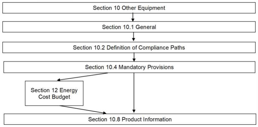
10. OTHER EQUIPMENT
10.1 General 10.1.1 Scope. This section applies to other equipment as described in Section 10.4. 10.1.2 New Building or Site System or Equipment. Other equipment installed in new buildings shall comply with the requirements of Section 10.2.
10.1.3 Additions to Existing Systems and Equipment. Other equipment installed in additions to exist- ing buildings and existing sites shall comply with the requirements of Section 10.2.
10.1.4 Alterations to Existing Service Equipment or Systems 10.1.4.1 Alterations to other building service equipment shall comply with the requirements of Section 10.2 as applicable to those specific portions of the building that are being altered. 10.1.4.2 Alterations to systems shall comply with the requirements of Section 10.2, as applicable to those specific portions that are being altered.
10.1.4.3 Any new equipment subject to the requirements of Section 10 that is installed in conjunction with the alterations as a direct replacement of existing equipment or control devices shall comply with the specific requirements applicable to that equipment or control devices .
Exception to 10.1.4.3: Compliance shall not be required for the relocation or reuse of existing equip-
ment .
10.1.5 Climate. Climate zones shall be determined in accordance with Section 5.1.5 .
10.2 Compliance Paths. Other equipment shall comply with Sections 10.2.1 and 10.2.2. 10.2.1 Requirements for All Compliance Paths. Other equipment shall comply with Sections 10.1, “General”; 10.4, “Mandatory Provisions”; 10.5, “Prescriptive Path”, and 10.8, “Product Information.”
10.2.2 Additional Requirements to Comply with Section 10 (Not Used)
10.3 Simplified Building Compliance Path (Not Used)
10.4 Mandatory Provisions 10.4.1 Electric Motors. Electric motors manufactured alone or as a component of another piece of equip- ment with a rated motor power of 1 hp or more, and less than or equal to 200 hp, shall comply with the requirements shown in Table 10.8-1 for NEMA Design A motors, NEMA Design B motors, and IEC Design N motors, and Table 10.8-2 for NEMA Design C motors and IEC Design H motors .
172 ANSI/ASHRAE/IES Standard 90.1-2022 (I-P)
PDF Page 175
General purpose small electric motors with an rated motor power of 0.25 hp or more, and less than or equal to 3 hp, shall have a minimum average full-load efficiency that is not less than as shown in Table 10.83 for polyphase small electric motors and Table 10.8-4 for capacitor-start capacitor-run small electric motors and capacitor-start induction-run small electric motors .
Fire pump electric motors shall have a minimum nominal full-load efficiency that is not less than that shown in Table 10.8-5.
Exception to 10.4.1: The standards in this section do not apply to the following exempt electric motors:
- Air-over electric motors.
- Component sets of an electric motor.
- Liquid-cooled electric motors.
- Submersible electric motors.
- Inverter-only electric motors.
10.4.2 Service Water Pressure Booster Systems. Service water pressure booster systems shall be designed such that the following apply:
a. One or more pressure sensors shall be used to vary pump speed and/or start and stop pumps . The sensors
shall either be located near the critical fixtures that determine the pressure required, or logic shall be employed that adjusts the set point to simulate operation of remote sensors. b. No devices shall be installed for the purpose of reducing the pressure of all of the water supplied by any
booster system pump or booster system, except for safety devices. c. No booster system pumps shall operate when there is no service water flow.
10.4.3 Elevators. Elevator systems shall comply with the requirements of this section.
10.4.3.1 Cab Lighting Power. For the luminaires in each elevator cab, not including power for germicidal function, signals, and displays, the sum of the lumens divided by the sum of the watts (as described in Section 9.1.4) shall be no less than 50 lm/W.
Exception to 10.4.3.1: This requirement does not apply to elevators in an essential facility where spe cial lighting needs are required.
10.4.3.2 Ventilation Efficacy. Cab ventilation for elevators, except elevators with air conditioning or MERV 13 or greater filters, shall have an efficacy of at least 4.0 cfm/W at maximum speed.
10.4.3.3 Standby Mode. The elevator cab lighting shall be automatically de-energized in accordance with ASME A17.1/CSA B44 Requirement 2.14.7.2.2. Cab ventilation fans for elevators without air conditioning shall also be de-energized.
When stopped and unoccupied with doors closed for over 15 minutes, cab interior lighting and ventila- tion shall be de-energized until required for operation.
Exception to 10.4.3.3: Forced ventilation shall meet the requirements of ASME A17.1/CSA B44
Requirement 2.14.2.3.3.
10.4.3.4 Energy Use. New elevators shall meet the following requirements:
a. Usage category as defined in ISO 25745-2 between 1 and 6. The usage category shall be in accordance
with Annex B. b. The energy efficiency class shall be E or better per ISO 25745-2, Table 7.
10.4.4 Escalators and Moving Walks. Escalators and moving walks shall automatically slow to the minimum permitted speed in accordance with ASME A17.1/CSA B44 or applicable local code when not conveying passengers.
10.4.5 Air Curtains. Air curtain unit performance shall be tested in accordance with ANSI/AMCA 220 or ISO 27327-1 and shall have a jet speed of not less than 6.6 ft/s at 6.0 in. above the floor . Automatic controls shall be provided that will operate the air curtain unit with the opening and closing of the door and comply with Section 6.4.3.9. To ensure proper operation, each air curtain unit shall be commissioned in accordance with the manufacturer ’s instructions, including airstream split location and direction.
10.4.6 Compressed Air Systems. All compressed air systems in factory industrial occupancies shall meet the requirements of Sections 10.4.6.1 through 10.4.6.5. These requirements apply to the compressors, related piping systems, and controls that provide compressed air. This section does not apply to any equip- ment or controls that use or process the compressed air.
Exception to 10.4.6: Medical air systems .
ANSI/ASHRAE/IES Standard 90.1-2022 (I-P) 173
PDF Page 176
10.4.6.1 Part-Load Controls and Efficiency. Compressed air systems where the total motor power is 25 hp or more shall be equipped with appropriately sized trim compressor(s) and primary storage. The compressed air system shall comply with either of the following:
a. The compressed air system shall include one or more variable-speed-drive (VSD) compressors. For sys-
tems with more than one compressor, the total combined capacity of the VSD compressor(s) acting as trim compressors must be at least 1.25 times the largest net capacity increment between combinations of compressors. The compressed air system shall include primary storage of at least 3 gal per actual cubic feet per minute (acfm) of the largest trim compressor . b. The total effective trim capacity of a compressor system is the size of the continuous operational range
where the specific power of the compressor(s) ( kW /100 acfm) is within 15% of the specific power at their most efficient operating point. The total effective trim capacity of the system is the sum of the effective trim capacity of the trim compressors .
Systems shall include primary storage of at least 4 gal/acfm of the largest trim compressor and meet (1) or (2) as follows:
-
S ystems with more than one compressor, not including backup compressors, shall include a compressor or set of compressors with total effective trim capacity at least the size of the largest net capacity increment between combinations of compressors, or the size of the smallest compressor, whichever is larger.
-
For s ystems with one compressor, not including backup compressors, the total effective trim capacity shall include the range from 70% to 100% of rated capacity. Exceptions to 10.4.6.1:
-
Alterations where the total combined added or replaced compressor motor power is less than the average per-compressor power of all compressors in the system .
-
Alterations where all added or replaced compressors are VSD compressors and the compressed air system includes primary storage of at least 3 gal/acfm of the largest trim compressor.
-
Compressed air systems that have been approved by the authority having jurisdiction as having demonstrated that the system serves loads for which typical air demand fluctuates less than 10%.
-
Alterations of existing compressed air systems that include one or more centrifugal compressors.
10.4.6.2 Controls. Compressed air systems with three or more compressors, including backup compressors, with a combined input power of more than 150 hp shall operate with controls that are able to choose the most energy -efficient combination and loading of compressors in the system based on the current compressed air demand.
10.4.6.3 Monitoring. Compressed air systems having a combined input power rating equal to or greater than 150 hp shall have an energy and air demand monitoring system with the following minimum requirements:
a. Measurement of system pressure b. Measurement or calculation of current or power of each compressor c. Measurement or determination of total airflow from all compressors in acfm d. Data logging of pressure, power in kW, airflow in acfm, and compressed air system specific power in kW /
100 acfm at intervals of five minutes or less e. The equipment shall be configured to record not less than six months of data and shall be capable of
exporting the data. f. Visual trending display of each recorded point, load, and specific power.
10.4.6.4 Leak Testing of Compressed Air Piping. Compressed air system piping shall be pressure tested after being isolated from the compressed air supply, storage tanks, and end uses. The piping shall be pressurized to the design operating pressure and the pressure allowed to stabilize. Test pressures shall be held for no less than 30 minutes, with no loss of pressure greater than 1.0%.
For piping less than or equal to 50 adjoining feet in length, connections shall optionally be tested with a noncorrosive leak-detecting fluid or other leak detecting methods at the discretion of the authority having jurisdiction .
10.4.6.5 Pipe Sizing. For new systems and additions to systems with operating pressures above 50 psig, compressed air piping greater than 50 adjoining feet in length shall be designed and installed to minimize frictional losses in the distribution network.
Service line piping that delivers compressed air from distribution piping to end uses shall have inner diameters greater than or equal to 1 in.
Added or replaced piping in existing systems shall meet the requirements of Section 10.4.6.5(a). New systems shall meet the requirements of either Section 10.4.6.5(a) or (b).
174 ANSI/ASHRAE/IES Standard 90.1-2022 (I-P)
PDF Page 177
a. Piping section average velocity: Compressor room interconnection and main header piping shall be sized
so that at coincident peak flow conditions the average velocity in the segment of pipe is no greater than 20 ft/s. Compressor room interconnection and main header piping are the pipes that deliver compressed air from the compressor outlets to the inlet to the distribution piping . Each segment of distribution and service piping shall be sized so that at coincident peak flow conditions the average velocity in the segment of pipe is no greater than 30 ft/s. Distribution piping is pipes that deliver compressed air from the compressor room interconnection piping or main header piping to the service line piping . b. Piping total pressure drop : Piping shall be designed such that piping frictional pressure loss at coincident
peak loads are less than 5% of operating pressure between the compressor and connection at point of use, prior to any end-use regulators.
10.4.7 Whole-Building Energy Monitoring. Measurement devices shall be installed at the building site to monitor the energy use of each new building .
10.4.7.1 Monitoring. Measurement devices shall be installed to monitor the building use of the following types of energy supplied by a utility, energy provider, or plant that is not within the building :
a. Natural gas b. Fuel oil c. Propane d. Steam e. Chilled water f. Hot water
10.4.7.2 Recording and Reporting. The energy use of each building on the building site shall be recorded at a minimum of every 60 minutes and reported at least hourly, daily, monthly, and annually. The system shall be capable of maintaining all data collected for a minimum of 36 months and creating user reports showing at least hourly, daily, monthly, and annual energy consumption and demand .
Exceptions to 10.4.7.1 and 10.4.7.2:
- Buildings or additions less than 25,000 ft [2] .
- Individual tenant spaces less than 10,000 ft [2] .
- Dwelling units .
- Residential buildings with less than 10,000 ft [2] of common area.
- Fuel used for on- site emergency equipment .
10.4.8 Pumps. Clean water pumps meeting the following criteria shall comply with the requirements shown in Table 10.8-6:
a. A flow rate of 25 gal/min or greater at its best efficiency point (BEP) at full impeller diameter b. Maximum head of 459 ft at its BEP at full impeller diameter and the number of stages required for testing c. Design temperature range from 14°F to 248°F d. Designed to operate with either
-
a 2- or 4-pole induction motor or
-
a noninduction motor with a speed of rotation operating range that includes speeds of rotation between 2880 and 4320 rpm and/or 1440 and 2160 rpm, and
-
in either (1) or (2), the driver and impeller must rotate at the same speed e. For submersible turbine pumps, a 6 in. or smaller bowl diameter f. For end-suction close-coupled pumps and end-suction frame-mounted/own bearings pumps, specific speed less than or equal to 5000 rpm when calculated using U.S. customary units Exceptions to 10.4.8: The standards in this section do not apply to the following pumps :
-
Fire pumps .
-
Self-priming pump .
-
Prime-assist pumps .
-
Magnet-driven pumps .
-
Pumps designed to be used in a nuclear facility subject to 10 CFR 50, “Domestic Licensing of Production and Utilization Facilities.”
-
Pumps meeting the design and construction requirements set forth in U.S. Military Specification MIL-P-17639F, “Pumps, Centrifugal, Miscellaneous Service, Naval Shipboard Use” (as amended); MIL-P-17881D, “Pumps, Centrifugal, Boiler Feed, (Multi-Stage)” (as amended); MIL-P-17840C, “Pumps, Centrifugal, Close-Coupled, Navy Standard (For Surface Ship Application)” (as amended); MIL-P-18682D, “Pump, Centrifugal, Main Condenser Circulating, Naval Shipboard”
ANSI/ASHRAE/IES Standard 90.1-2022 (I-P) 175
PDF Page 178
(as amended); MIL-P-18472G, “Pumps, Centrifugal, Condensate, Feed Booster, Waste Heat Boiler, And Distilling Plant” (as amended).
Informative Note: Informative Appendix E contains additional information on pump nomenclature and definitions which are available from ANSI-HI 1.1-1.2-2014 and ANSI-HI 2.1-2.2-2014.
10.5 Prescriptive Compliance Path 10.5.1 Renewable Energy Resources . Buildings shall be served by renewable energy resources complying with Section 10.5.1.1.
10.5.1.1 On-Site Renewable Energy. The building site shall have equipment for on-site renewable energy with a rated capacity of not less than 0.50 W/ft [2] or 1.7 Btu/ft [2] multiplied by the sum of the gross con- ditioned floor area for all floors up to the three largest floors.
Exceptions to 10.5.1.1:
- Any building located where an unshaded flat plate collector oriented toward the equator and tilted at an angle from horizontal equal to the latitude receives an annual daily average incident solar radiation less than 1.1 kBtu/ft [2] ·day.
- Any building where more than 80% of the roof area is covered by any combination of equipment other than for on-site renewable energy systems, planters, vegetated space, skylights, or occupied roof deck.
- Any building where more than 50% of roof area is shaded from direct-beam sunlight by natural objects or by structures that are not part of the building for more than 2500 annual hours between 8:00 a.m. and 4:00 p.m.
- New construction or additions in which the sum of the gross conditioned floor area of the three largest floors of the new construction or addition is less than 10,000 ft [2] .
- Alterations .
10.6 Alternative Compliance Path (Not Used)
10.7 Submittals 10.7.1 General. Compliance documentation and supplemental information shall be submitted in accordance with Section 4.2.2 of this standard.
10.7.2 Permit Application Documentation (Not Used) 10.7.3 Completion Requirements 10.7.3.1 Record Documents. Construction documents shall require that within 90 days after the date of system acceptance, record documents shall be provided to the building owner.
10.7.3.2 Manuals (Not Used)
10.8 Product Information
10.9 Verification, Testing, Commissioning, and Documentation 10.9.1 Verification and Testing. Other applicable equipment shall be verified and tested in accordance with this section and Section 4.2.5.1. Testing shall verify that control elements and monitoring systems are configured and operating in accordance with Section 10.4.2, 10.4.3.3, 10.4.5, and 4.2.5.2. FPT documentation shall comply with applicable requirements of
a. service water pressure-booster system controls (Section 10.4.2), b. elevator standby mode (Section 10.4.3.3), c. air curtains (Section 10.4.5), d. whole- building energy monitoring (Section 10.4.7), and e. pumps (Section 10.4.8).
Verification and FPT documentation shall comply with Section 4.2.5.1.2. 10.9.2 Commissioning. The energy performance of the other equipment systems shall be commissioned in accordance with Section 4.2.5.2 and reporting shall comply with Section 4.2.5.2.2.
Informative Note: See Informative Appendix E and Informative Appendix H for commissioning resources.
10.9.3 Documentation. Design documents shall list the following for new elevators:
a. The usage category as defined in ISO 25745-2 between 1 and 6. The usage category shall be in accor dance with Annex B. b. The energy efficiency class per ISO 25745-2, Table 7.
176 ANSI/ASHRAE/IES Standard 90.1-2022 (I-P)
PDF Page 179
Table 10.8-1 Minimum Nominal Full-Load Efficiency for NEMA Design A, NEMA Design B, and IEC Design N Motors (Excluding Fire Pump Electric Motors) at 60 Hz [a,b]
| Motor Horsepower, hp | Nominal Full-Load Efficiency, % | Col3 | Col4 | Col5 | Col6 | Col7 | Col8 | Col9 |
|---|---|---|---|---|---|---|---|---|
| Motor Horsepower, hp | 2-Pole | 2-Pole | 4-Pole | 4-Pole | 6-Pole | 6-Pole | 8-Pole | 8-Pole |
| Motor Horsepower, hp | Enclosed | Open | Enclosed | Open | Enclosed | Open | Enclosed | Open |
| 1 | 77.0 | 77.0 | 85.5 | 85.5 | 82.5 | 82.5 | 75.5 | 75.5 |
| 1.5 | 84.0 | 84.0 | 86.5 | 86.5 | 87.5 | 86.5 | 78.5 | 77.0 |
| 2 | 85.5 | 85.5 | 86.5 | 86.5 | 88.5 | 87.5 | 84.0 | 86.5 |
| 3 | 86.5 | 85.5 | 89.5 | 89.5 | 89.5 | 88.5 | 85.5 | 87.5 |
| 5 | 88.5 | 86.5 | 89.5 | 89.5 | 89.5 | 89.5 | 86.5 | 88.5 |
| 7.5 | 89.5 | 88.5 | 91.7 | 91.0 | 91.0 | 90.2 | 86.5 | 89.5 |
| 10 | 90.2 | 89.5 | 91.7 | 91.7 | 91.0 | 91.7 | 89.5 | 90.2 |
| 15 | 91.0 | 90.2 | 92.4 | 93.0 | 91.7 | 91.7 | 89.5 | 90.2 |
| 20 | 91.0 | 91.0 | 93.0 | 93.0 | 91.7 | 92.4 | 90.2 | 91.0 |
| 25 | 91.7 | 91.7 | 93.6 | 93.6 | 93.0 | 93.0 | 90.2 | 91.0 |
| 30 | 91.7 | 91.7 | 93.6 | 94.1 | 93.0 | 93.6 | 91.7 | 91.7 |
| 40 | 92.4 | 92.4 | 94.1 | 94.1 | 94.1 | 94.1 | 91.7 | 91.7 |
| 50 | 93.0 | 93.0 | 94.5 | 94.5 | 94.1 | 94.1 | 92.4 | 92.4 |
| 60 | 93.6 | 93.6 | 95.0 | 95.0 | 94.5 | 94.5 | 92.4 | 93.0 |
| 75 | 93.6 | 93.6 | 95.4 | 95.0 | 94.5 | 94.5 | 93.6 | 94.1 |
| 100 | 94.1 | 93.6 | 95.4 | 95.4 | 95.0 | 95.0 | 93.6 | 94.1 |
| 125 | 95.0 | 94.1 | 95.4 | 95.4 | 95.0 | 95.0 | 94.1 | 94.1 |
| 150 | 95.0 | 94.1 | 95.8 | 95.8 | 95.8 | 95.4 | 94.1 | 94.1 |
| 200 | 95.4 | 95.0 | 96.2 | 95.8 | 95.8 | 95.4 | 94.5 | 94.1 |
| 250 | 95.8 | 95.0 | 96.2 | 95.8 | 95.8 | 95.8 | 95.0 | 95.0 |
| 300 | 95.8 | 95.4 | 96.2 | 95.8 | 95.8 | 95.8 | NR | NR |
| 350 | 95.8 | 95.4 | 96.2 | 95.8 | 95.8 | 95.8 | NR | NR |
| 400 | 95.8 | 95.8 | 96.2 | 95.8 | NR | NR | NR | NR |
| 450 | 95.8 | 96.2 | 96.2 | 96.2 | NR | NR | NR | NR |
| 500 | 95.8 | 96.2 | 96.2 | 96.2 | NR | NR | NR | NR |
a. Nominal efficiencies shall be established in accordance with DOE 10 CFR 431. b. For purposes of determining the required minimum nominal full-load efficiency of an electric motor that has a horsepower or kilowatt rating between two horsepower or two kilo-
watt ratings listed in this table, each such motor shall be deemed to have a listed horsepower or kilowatt rating, determined as follows:
- A horsepower at or above the midpoint between the two consecutive horsepowers shall be rounded up to the higher of the two horsepowers.
- A horsepower below the midpoint between the two consecutive horsepowers shall be rounded down to the lower of the two horsepowers.
- A kilowatt rating shall be directly converted from kilowatts to horsepower using the formula 1 kilowatt = (1/0.746) horsepower. The conversion should be calculated to three significant decimal places, and the resulting horsepower shall be rounded in accordance with paragraph (1) or (2), whichever applies. c. NR = no requirement.
ANSI/ASHRAE/IES Standard 90.1-2022 (I-P) 177
PDF Page 180
Table 10.8-2 Minimum Nominal Full-Load Efficiency for NEMA Design C and IEC Design H Motors at 60 Hz [ a,b]
| Motor Horsepower, hp | Nominal Full-Load Efficiency, % | Col3 | Col4 | Col5 | Col6 | Col7 |
|---|---|---|---|---|---|---|
| Motor Horsepower, hp | 4-Pole | 4-Pole | 6-Pole | 6-Pole | 8-Pole | 8-Pole |
| Motor Horsepower, hp | Enclosed | Open | Enclosed | Open | Enclosed | Open |
| 1 | 85.5 | 85.5 | 82.5 | 82.5 | 75.5 | 75.5 |
| 1.5 | 86.5 | 86.5 | 87.5 | 86.5 | 78.5 | 77.0 |
| 2 | 86.5 | 86.5 | 88.5 | 87.5 | 84.0 | 86.5 |
| 3 | 89.5 | 89.5 | 89.5 | 88.5 | 85.5 | 87.5 |
| 5 | 89.5 | 89.5 | 89.5 | 89.5 | 86.5 | 88.5 |
| 7.5 | 91.7 | 91.0 | 91.0 | 90.2 | 86.5 | 89.5 |
| 10 | 91.7 | 91.7 | 91.0 | 91.7 | 89.5 | 90.2 |
| 15 | 92.4 | 93.0 | 91.7 | 91.7 | 89.5 | 90.2 |
| 20 | 93.0 | 93.0 | 91.7 | 92.4 | 90.2 | 91.0 |
| 25 | 93.6 | 93.6 | 93.0 | 93.0 | 90.2 | 91.0 |
| 30 | 93.6 | 94.1 | 93.0 | 93.6 | 91.7 | 91.7 |
| 40 | 94.1 | 94.1 | 94.1 | 94.1 | 91.7 | 91.7 |
| 50 | 94.5 | 94.5 | 94.1 | 94.1 | 92.4 | 92.4 |
| 60 | 95.0 | 95.0 | 94.5 | 94.5 | 92.4 | 93.0 |
| 75 | 95.4 | 95.0 | 94.5 | 94.5 | 93.6 | 94.1 |
| 100 | 95.4 | 95.4 | 95.0 | 95.0 | 93.6 | 94.1 |
| 125 | 95.4 | 95.4 | 95.0 | 95.0 | 94.1 | 94.1 |
| 150 | 95.8 | 95.8 | 95.8 | 95.4 | 94.1 | 94.1 |
| 200 | 96.2 | 95.8 | 95.8 | 95.4 | 94.5 | 94.1 |
a. Nominal efficiencies shall be established in accordance with DOE 10 CFR 431. b. For purposes of determining the required minimum nominal full-load efficiency of an electric motor that has a horsepower or kilowatt rating between two horsepower or two kilo-
watt ratings listed in this table, each such motor shall be deemed to have a listed horsepower or kilowatt rating, determined as follows: 1.A horsepower at or above the midpoint between the two consecutive horsepowers shall be rounded up to the higher of the two horsepowers. 2.A horsepower below the midpoint between the two consecutive horsepowers shall be rounded down to the lower of the two horsepowers. 3.A kilowatt rating shall be directly converted from kilowatts to horsepower using the formula 1 kilowatt = (1/0.746) horsepower. The conversion should be calculated to three significant decimal places, and the resulting horsepower shall be rounded in accordance with paragraph (1) or (2), whichever applies.
Table 10.8-3 Minimum Average Full-Load Efficiency for Polyphase Small Electric Motors [ a]
| Number of Poles | Full-Load Efficiency, % | Col3 | Col4 |
|---|---|---|---|
| Number of Poles | Open Motors | Open Motors | Open Motors |
| Number of Poles | 2 | 4 | 6 |
| **Synchronous Speed (RPM)** | 3600 | 1800 | 1200 |
| Motor Size, hp | Col2 | Col3 | Col4 |
|---|---|---|---|
| 0.25 | 65.6 | 69.5 | 67.5 |
| 0.33 | 69.5 | 73.4 | 71.4 |
| 0.50 | 73.4 | 78.2 | 75.3 |
| 0.75 | 76.8 | 81.1 | 81.7 |
| 1 | 77.0 | 83.5 | 82.5 |
| 1.5 | 84.0 | 86.5 | 83.8 |
| 2 | 85.5 | 86.5 | N/A |
| 3 | 85.5 | 86.9 | N/A |
a. Average full-load efficiencies shall be established in accordance with 10 CFR 431.
178 ANSI/ASHRAE/IES Standard 90.1-2022 (I-P)
PDF Page 181
Table 10.8-4 Minimum Average Full-Load Efficiency for Capacitor-Start Capacitor-Run and Capacitor-Start Induction-Run Small Electric Motors [a]
| Number of Poles | Full-Load Efficiency, % | Col3 | Col4 |
|---|---|---|---|
| Number of Poles | Open Motors | Open Motors | Open Motors |
| Number of Poles | 2 | 4 | 6 |
| **Synchronous Speed (RPM)** | 3600 | 1800 | 1200 |
| Motor Size, hp | Col2 | Col3 | Col4 |
|---|---|---|---|
| 0.25 | 66.6 | 68.5 | 62.2 |
| 0.33 | 70.5 | 72.4 | 66.6 |
| 0.50 | 72.4 | 76.2 | 76.2 |
| 0.75 | 76.2 | 81.8 | 80.2 |
| 1 | 80.4 | 82.6 | 81.1 |
| 1.5 | 81.5 | 83.8 | N/A |
| 2 | 82.9 | 84.5 | N/A |
| 3 | 84.1 | N/A | N/A |
a. Average full-load efficiencies shall be established in accordance with 10 CFR 431.
Table 10.8-5 Minimum Nominal Full-Load Efficiency for Fire Pump Electric Motors [a]
| Number of Poles | Full-Load Efficiency, % | Col3 | Col4 | Col5 | Col6 | Col7 | Col8 | Col9 |
|---|---|---|---|---|---|---|---|---|
| Number of Poles | Open Drip-Proof Motors | Open Drip-Proof Motors | Open Drip-Proof Motors | Open Drip-Proof Motors | Totally Enclosed Fan-Cooled Motors | Totally Enclosed Fan-Cooled Motors | Totally Enclosed Fan-Cooled Motors | Totally Enclosed Fan-Cooled Motors |
| Number of Poles | 2 | 4 | 6 | 8 | 2 | 4 | 6 | 8 |
| **Synchronous Speed (RPM)** | 3600 | 1800 | 1200 | 900 | 3600 | 1800 | 1200 | 900 |
| Motor Size, hp | Col2 | Col3 | Col4 | Col5 | Col6 | Col7 | Col8 | Col9 |
|---|---|---|---|---|---|---|---|---|
| 1 | NR | 82.5 | 80.0 | 74.0 | 75.5 | 82.5 | 80.0 | 74.0 |
| 1.5 | 82.5 | 84.0 | 84.0 | 75.5 | 82.5 | 84.0 | 85.5 | 77.0 |
| 2 | 84.0 | 84.0 | 85.5 | 85.5 | 84.0 | 84.0 | 86.5 | 82.5 |
| 3 | 84.0 | 86.5 | 86.5 | 86.5 | 85.5 | 87.5 | 87.5 | 84.0 |
| 5 | 85.5 | 87.5 | 87.5 | 87.5 | 87.5 | 87.5 | 87.5 | 85.5 |
| 7.5 | 87.5 | 88.5 | 88.5 | 88.5 | 88.5 | 89.5 | 89.5 | 85.5 |
| 10 | 88.5 | 89.5 | 90.2 | 89.5 | 89.5 | 89.5 | 89.5 | 88.5 |
| 15 | 89.5 | 91.0 | 90.2 | 89.5 | 90.2 | 91.0 | 90.2 | 88.5 |
| 20 | 90.2 | 91.0 | 91.0 | 90.2 | 90.2 | 91.0 | 90.2 | 89.5 |
| 25 | 91.0 | 91.7 | 91.7 | 90.2 | 91.0 | 92.4 | 91.7 | 89.5 |
| 30 | 91.0 | 92.4 | 92.4 | 91.0 | 91.0 | 92.4 | 91.7 | 91.0 |
| 40 | 91.7 | 93.0 | 93.0 | 91.0 | 91.7 | 93.0 | 93.0 | 91.0 |
| 50 | 92.4 | 93.0 | 93.0 | 91.7 | 92.4 | 93.0 | 93.0 | 91.7 |
| 60 | 93.0 | 93.6 | 93.6 | 92.4 | 93.0 | 93.6 | 93.6 | 91.7 |
| 75 | 93.0 | 94.1 | 93.6 | 93.6 | 93.0 | 94.1 | 93.6 | 93.0 |
| 100 | 93.0 | 94.1 | 94.1 | 93.6 | 93.6 | 94.5 | 94.1 | 93.0 |
| 125 | 93.6 | 94.5 | 94.1 | 93.6 | 94.5 | 94.5 | 94.1 | 93.6 |
| 150 | 93.6 | 95.0 | 94.5 | 93.6 | 94.5 | 95.0 | 95.0 | 93.6 |
| 200 | 94.5 | 95.0 | 94.5 | 93.6 | 95.0 | 95.0 | 95.0 | 94.1 |
| 250 | 94.5 | 95.4 | 95.4 | 94.5 | 95.4 | 95.0 | 95.0 | 94.5 |
ANSI/ASHRAE/IES Standard 90.1-2022 (I-P) 179
PDF Page 182
Table 10.8-5 Minimum Nominal Full-Load Efficiency for Fire Pump Electric Motors [a] (Continued)
| Number of Poles | Full-Load Efficiency, % | Col3 | Col4 | Col5 | Col6 | Col7 | Col8 | Col9 |
|---|---|---|---|---|---|---|---|---|
| Number of Poles | Open Drip-Proof Motors | Open Drip-Proof Motors | Open Drip-Proof Motors | Open Drip-Proof Motors | Totally Enclosed Fan-Cooled Motors | Totally Enclosed Fan-Cooled Motors | Totally Enclosed Fan-Cooled Motors | Totally Enclosed Fan-Cooled Motors |
| Number of Poles | 2 | 4 | 6 | 8 | 2 | 4 | 6 | 8 |
| **Synchronous Speed (RPM)** | 3600 | 1800 | 1200 | 900 | 3600 | 1800 | 1200 | 900 |
| Motor Size, hp | Col2 | Col3 | Col4 | Col5 | Col6 | Col7 | Col8 | Col9 |
|---|---|---|---|---|---|---|---|---|
| 300 | 95.0 | 95.4 | 95.4 | NR | 95.4 | 95.4 | 95.0 | NR |
| 350 | 95.0 | 95.4 | 95.4 | NR | 95.4 | 95.4 | 95.0 | NR |
| 400 | 95.4 | 95.4 | NR | NR | 95.4 | 95.4 | NR | NR |
| 450 | 95.8 | 95.8 | NR | NR | 95.4 | 95.4 | NR | NR |
| 500 | 95.8 | 95.8 | NR | NR | 95.4 | 95.8 | NR | NR |
a. Nominal efficiencies shall be established in accordance with DOE 10 CFR 431. b. For purposes of determining the required minimum nominal full-load efficiency of an electric motor that has a horsepower or kilowatt rating between two horsepower or two kilo-
watt ratings listed in this table, each such motor shall be deemed to have a listed horsepower or kilowatt rating, determined as follows: 1.A horsepower at or above the midpoint between the two consecutive horsepowers shall be rounded up to the higher of the two horsepowers. 2.A horsepower below the midpoint between the two consecutive horsepowers shall be rounded down to the lower of the two horsepowers. 3.A kilowatt rating shall be directly converted from kilowatts to horsepower using the formula 1 kilowatt = (1/0.746) horsepower. The conversion should be calculated to three significant decimal places, and the resulting horsepower shall be rounded in accordance with paragraph (1) or (2), whichever applies. NR—No requirement
Table 10.8-6 Maximum Pump Energy Index (PEI)
Maximum PEI for Pumps Manufactured on or after January 27, 2020
| Pump Type | Nominal Speed of Rotation (RPM) | Operating Mode | Maximum PEI a | C-Value b | Test Procedure |
|---|---|---|---|---|---|
| End suction, close coupled | 1800 | Constant load | 1.00 | 128.47 | 10 CFR Part 431 |
| End suction, close coupled | 3600 | Constant load | 1.00 | 130.42 | 10 CFR Part 431 |
| End suction, close coupled | 1800 | Variable load | 1.00 | 128.47 | 10 CFR Part 431 |
| End suction, close coupled | 3600 | Variable load | 1.00 | 130.42 | 10 CFR Part 431 |
| End suction, frame mounted | 1800 | Constant load | 1.00 | 128.85 | 10 CFR Part 431 |
| End suction, frame mounted | 3600 | Constant load | 1.00 | 130.99 | 10 CFR Part 431 |
| End Suction, frame mounted | 1800 | Variable load | 1.00 | 128.85 | 10 CFR Part 431 |
| End suction, frame mounted | 3600 | Variable load | 1.00 | 130.99 | 10 CFR Part 431 |
| In-line | 1800 | Constant load | 1.00 | 129.30 | 10 CFR Part 431 |
| In-line | 3600 | Constant load | 1.00 | 133.84 | 10 CFR Part 431 |
| In-line | 1800 | Variable load | 1.00 | 129.30 | 10 CFR Part 431 |
| In-line | 3600 | Variable load | 1.00 | 133.84 | 10 CFR Part 431 |
| Radially split, vertical | 1800 | Constant load | 1.00 | 129.63 | 10 CFR Part 431 |
| Radially split, vertical | 3600 | Constant load | 1.00 | 133.20 | 10 CFR Part 431 |
| Radially split, vertical | 1800 | Variable load | 1.00 | 129.63 | 10 CFR Part 431 |
| Radially split, vertical | 3600 | Variable load | 1.00 | 133.20 | 10 CFR Part 431 |
| Submersible turbine | 1800 | Constant load | 1.00 | 138.78 | 10 CFR Part 431 |
| Submersible turbine | 3600 | Constant load | 1.00 | 134.85 | 10 CFR Part 431 |
| Submersible turbine | 1800 | Variable load | 1.00 | 138.78 | 10 CFR Part 431 |
| Submersible turbine | 3600 | Variable load | 1.00 | 134.85 | 10 CFR Part 431 |
a. For pumps with the constant load operating mode, the relevant PEI is PEICL . For pumps with the variable load operating mode, the relevant PEI is PEIVL . b. The C-values shown in this table shall be used in the equation for PEISTD when calculating PEICL or PEIVL.
180 ANSI/ASHRAE/IES Standard 90.1-2022 (I-P)
PDF Page 183
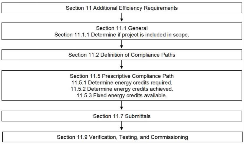
11. ADDITIONAL EFFICIENCY REQUIREMENTS
11.1 General
a. HVAC systems that account for more than 50% of the capacity serving either the heating or cooling loads
of the alteration area. This includes HVAC unitary systems, HVAC terminal units, or components of HVAC central heating or cooling equipment, not including ductwork or piping . HVAC terminal units, for the purposes of this section, can include VAV boxes, fan-coil units, VRF room units, or water-loop heat pumps. b. Fifty percent (50%) or more of the luminaires in the alteration area c. Twenty-five percent (25%) or more of the building envelope area of the alteration portion of the build-
ing, including new exterior cladding, fenestration, or insulation
Informative Note: Substantial alterations are intended to include a major renovation of part or all of an existing building that extends the life of the building and includes major replacement of at least two major building systems .
11.1.4.2 Initial Build-Out Construction. The building envelope, equipment, and systems in initial build-out construction exceeding 1000 ft [2] of gross floor area in buildings where the alteration did not have final lighting or HVAC systems installed under a prior building permit shall comply with the requirements of Section 11.2.
ANSI/ASHRAE/IES Standard 90.1-2022 (I-P) 181
PDF Page 184
10
11
11.1.5 Climate. Climate zones shall be determined in accordance with Section 5.1.5.
11.2 Compliance Paths. New buildings, additions, substantial alterations as described in Section 11.1.4.1,
11.2.2 Additional Requirements to Comply with Section 11 (Not used)
11.3 Simplified Building Compliance Path (Not used)


Informative Note: The energy credit values in Table 11.5.1-1 and Tables 11.5.3-1 through 11.5.3-9 represent about 0.1% total building annual energy cost savings per point.
11.5.1 Energy Credits Required. Projects shall achieve the total of credits required in Table 11.5.1-1 based on the building use type and climate zone. Projects with multiple building use types, unconditioned or semiheated buildings, parking garages, projects using on-site renewable energy, alterations, and buildings with separate shell-and-core and initial build-out construction permits shall comply as follows:
a. Where a project contains multiple building use types or situations covered in items (b), (c), and (d)
- The building core and shell project shall achieve at least 50% of the energy credits required in Table 11.5.1-1 where the core and shell project includes a central HVAC system or service water heating system that includes chillers, boilers, service water heating equipment, or loop pumping systems with heat rejection. Otherwise, the building core and shell project shall achieve at least 33% of the energy credits required in Table 11.5.1-1. The building core and shell permit shall not be eligible for credits from measures involving nonpermanent services in future build-out areas, such as freeze protection and limited lighting.
- Initial build-out construction, as described in Section 11.1.4.2, shall be deemed to comply with this section where one of the following applies: i. Where the initial build-out project includes HVAC heating and cooling generation equipment, the energy credits achieved under the initial build-out project are not less than 50% of the credits required in Table 11.5.1-1. ii. Where the initial build-out project receives heating and cooling services from the core and shell
building —excluding condenser loop water—the energy credits achieved under the initial buildout project are not less than 25% of the credits required in Table 11.5.1-1. iii. The energy credits achieved under the initial build-out project, plus the energy credits achieved
under a prior core and shell permit—not including core and shell credits from measures L02, L03, L04, L05, L06, G01, or G02—total at least the credits required in Table 11.5.1-1.
d. Unconditioned spaces, semiheated spaces, and parking garages shall achieve 50% of the credits required
for the “Other” building use type in Table 11.5.1-1. e. Where roof space or insolation available for on-site renewable energy is limited according to the defini tion of RA net in Equation 11.5.1, the energy credit requirement in Table 11.5.1-1 shall be adjusted and EC adj used in place of EC req, where EC adj is determined using one of the following:
- Where the project meets any exception to Section 10.5.1.1, the PV adj credits shall be subtracted from the credits required for the climate zone to find EC adj .
- Otherwise, energy credits adjusted for renewable energy resource availability shall be determined as follows:

182 ANSI/ASHRAE/IES Standard 90.1-2022 (I-P)
PDF Page 185
12
Table 11.5.1-1 Energy Credit Requirements by Building Use Type
| Building Use Type a | Climate Zone | Col3 | Col4 | Col5 | Col6 | Col7 | Col8 | Col9 | Col10 | Col11 | Col12 | Col13 | Col14 | Col15 | Col16 | Col17 | Col18 | Col19 | Col20 |
|---|---|---|---|---|---|---|---|---|---|---|---|---|---|---|---|---|---|---|---|
| Building Use Typea | 0A | 0B | 1A | 1B | 2A | 2B | 3A | 3B | 3C | 4A | 4B | 4C | 5A | 5B | 5C | 6A | 6B | 7 | 8 |
| Multifamilyb | 50 | 50 | 50 | 50 | 50 | 50 | 46 | 50 | 50 | 48 | 50 | 46 | 50 | 50 | 49 | 50 | 50 | 50 | 50 |
| Health carec | 50 | 46 | 47 | 46 | 47 | 45 | 49 | 47 | 50 | 46 | 46 | 50 | 50 | 50 | 50 | 50 | 50 | 50 | 50 |
| Hotel/motel | 50 | 45 | 47 | 46 | 49 | 48 | 46 | 47 | 50 | 48 | 50 | 50 | 47 | 46 | 47 | 49 | 46 | 50 | 50 |
| Officed | 50 | 50 | 50 | 50 | 50 | 50 | 50 | 50 | 50 | 50 | 50 | 50 | 50 | 50 | 50 | 50 | 50 | 50 | 50 |
| Restaurante | 50 | 50 | 50 | 50 | 50 | 50 | 50 | 50 | 50 | 50 | 50 | 50 | 50 | 50 | 50 | 50 | 50 | 50 | 50 |
| Retail | 50 | 50 | 50 | 50 | 50 | 50 | 50 | 50 | 50 | 50 | 50 | 50 | 49 | 50 | 47 | 48 | 45 | 42 | 46 |
| Educationf | 50 | 50 | 50 | 50 | 50 | 50 | 50 | 50 | 50 | 50 | 50 | 50 | 50 | 50 | 50 | 50 | 50 | 50 | 46 |
| Warehouseg | 50 | 50 | 50 | 50 | 50 | 50 | 50 | 50 | 50 | 50 | 50 | 50 | 50 | 50 | 50 | 50 | 50 | 50 | 50 |
| Otherh | 39 | 36 | 37 | 37 | 35 | 34 | 30 | 32 | 33 | 28 | 32 | 30 | 29 | 31 | 30 | 29 | 30 | 29 | 29 |
a. All building use types include supporting functions such as corridors, break rooms, lobbies, restrooms, mechanical rooms, storage rooms, conference rooms, individual equipment
and computer rooms with loads ≤10 kW, minor snack and beverage service without a commercial kitchen, and up to 10% of gross floor area of other building use types such as an office area less than 2000 ft [2] in a nonoffice building use type. b. “Multifamily” includes apartments, condominiums, dormitories, retirement living facilities, nontransient lodging, and residential portions of institutional care facilities, excluding
prisons. c. “Health Care” includes buildings within the scope of ASHRAE Standard 170 ventilation requirements that are dedicated to patient care, including related support areas of health
care facilities, hospitals, nursing facilities, outpatient facilities, and surgery centers. d. Office includes offices or clinics where medical, dental, psychotherapy, physical therapy or other services are provided that are not within the scope of ASHRAE Standard 170
ventilation requirements. e. Restaurants with commercial kitchens and dining areas that are separate buildings or constructed under separate permits shall meet restaurant building use type requirements. Where
restaurants are part of a larger building and are not seeking credit for either measure W01, W02, W03, or Q02, their area is permitted to be included with the larger building use type. f. Education includes schools, lecture halls, gymnasiums, and libraries. g. Warehouse that are conditioned spaces, including storage and distribution building s, refrigerated warehouses, and storage rental facilities. h. All other buildings, including any building use not covered in the eight listed building use types above and data centers using Standard 90.4, shall use the energy credits required
and available for the “Other” category.
Table 11.5.1-2 Renewable Adjustment Credits
| Building Use Type | PV by Climate Zone adj | Col3 | Col4 | Col5 | Col6 | Col7 | Col8 | Col9 | Col10 | Col11 | Col12 | Col13 | Col14 | Col15 | Col16 | Col17 | Col18 | Col19 | Col20 | PV, incl W/ft2 |
|---|---|---|---|---|---|---|---|---|---|---|---|---|---|---|---|---|---|---|---|---|
| Building Use Type | 0A | 0B | 1A | 1B | 2A | 2B | 3A | 3B | 3C | 4A | 4B | 4C | 5A | 5B | 5C | 6A | 6B | 7 | 8 | 8 |
| Multifamily | 6 | 7 | 8 | 7 | 8 | 18 | 16 | 19 | 20 | 13 | 13 | 14 | 6 | 9 | 13 | 6 | 7 | 6 | 5 | 0.1 |
| Health care | 3 | 3 | 3 | 3 | 3 | 4 | 3 | 4 | 7 | 5 | 7 | 3 | 2 | 3 | 3 | 3 | 3 | 2 | 2 | 0.1 |
| Hotel/motel | 4 | 8 | 9 | 9 | 9 | 12 | 10 | 13 | 8 | 9 | 10 | 8 | 8 | 12 | 9 | 9 | 10 | 8 | 5 | 0.1 |
| Office | 6 | 6 | 7 | 7 | 12 | 8 | 8 | 9 | 10 | 7 | 9 | 7 | 6 | 8 | 7 | 6 | 7 | 6 | 5 | 0.1 |
| Restaurant | 1 | 1 | 1 | 1 | 1 | 2 | 1 | 2 | 2 | 1 | 2 | 1 | 1 | 1 | 1 | 1 | 1 | 1 | 1 | 0.1 |
| Retail | 5 | 5 | 6 | 6 | 7 | 8 | 14 | 17 | 16 | 7 | 14 | 12 | 10 | 14 | 12 | 10 | 12 | 10 | 7 | 0.1 |
| Education | 5 | 6 | 7 | 6 | 7 | 9 | 16 | 14 | 12 | 11 | 11 | 9 | 11 | 11 | 9 | 12 | 10 | 12 | 10 | 0.1 |
| Warehouse | 20 | 20 | 20 | 20 | 20 | 20 | 20 | 20 | 20 | 19 | 20 | 20 | 14 | 20 | 20 | 12 | 17 | 12 | 10 | 0.1 |
| Other | 6 | 6 | 7 | 7 | 7 | 8 | 7 | 9 | 9 | 7 | 9 | 7 | 5 | 8 | 7 | 6 | 7 | 5 | 4 | 0.1 |
EC adj = EC req - PV adj 1 - -------------------------------------------------- Gfloor RAPV netincl 0.20 -
(11.5.1)
where EC adj = adjusted energy credit requirement used instead of the energy credit requirement from Table 11.5.1-1 EC req = energy credit requirement from Table 11.5.1-1 PV adj = PV adj for building type from Table 11.5.1-2 RA net = horizontal projection of roof area available for renewable energy resources not covered by any
ANSI/ASHRAE/IES Standard 90.1-2022 (I-P) 183
PDF Page 186
13
combination of equipment other than for on-site renewable energy systems, planters, vegetated space, skylights, or occupied roof deck after meeting requirements of Section 10.5.1 Gfloor = gross floor area of building, ft [2]
PV incl = PV incl for building type from Table 11.5.1-2, W/ft [2]
Exceptions to 11.5.1:
-
Portions of buildings devoted to manufacturing or industrial use not including office areas.
-
Where the core/shell complies in accordance with Normative Appendix G or Section 12, the initial build-out alterations do not need to achieve any energy credits. Informative Notes:
-
Under Section 11.5.1(a), a building may be split into multiple building use types unless there is a small area less than 10% of the gross floor area of a different use type. Examples: A small managers office in a multifamily building, retail, or hotel would be included with the main multifamily or other use type, while a large administrative wing of a hospital (>10% of gross building area or greater than 2000 ft [2] ) would be a separate building use type. A coffee bar in the lobby of an office building or bookstore would be included with the office or retail use type, while a restaurant with a commercial kitchen in a hotel seeking hot water or kitchen equipment measures would be a separate building use type, regardless of relative size.
Where office areas 2000 ft [2] or more are associated with a larger building of a different type, such as a data center, warehouse, or hospital, the office area should be separated for energy credit treatment in the office building category, even if the special use was less than 10% of the total project building area. 2. The energy credit requirements in Table 11.5.1-1 are based on a cost-effectiveness analysis of a selection of credits that would typically be applied to each building use type. In all cases, photovoltaic renewable credits are included. The renewable credit adjustment in item (e) (based on Table 11.5.1-2) is included so that, where on-site renewable energy is not feasible, the required credits are appropriately reduced to match a typical cost-effective package of measures.
types, credits achieved for each building use type shall be weighted by the gross floor area of each building
a. The measure energy credit shall be the base energy credit for the measure, where no adjustment factor or
formula is shown in the measure description (e.g., EC H02_base ). b. The measure energy credit shall be the base energy credit for the measure, adjusted by a factor or formula
as stated in the measure description in this section. Where adjustments are applied, each measure energy credit shall be rounded to the nearest whole number (e.g., EC H02_adj ). c. The measure energy credit shall be by direct formula as stated in the measure description in this section,
where each measure credit shall be rounded to the nearest whole number (e.g., EC H02_calc ).
Informative Note: The number of energy credits achieved for each individual measure is determined in
one of three ways:
-
The base energy credit for the measure shown in Tables 11.5.3-1 through 11.5.3-9 for the building use type and climate zone where no adjustment factor or formula is shown in the measure description. This applies to the following measures:
-
H04: 11.5.2.2.4, “Residential Space HVAC Control”
-
H07: 11.5.2.2.7, “Improved HVAC Sequence of Operations”
-
W01: 11.5.2.3.1(a), “Heat Recovery for Service Hot-Water Preheating”
-
W05: 11.5.2.3.3(a), “Point-of-Use Water Heater”
-
W06: 11.5.2.3.3(b), “Thermostatic Balancing Valves”
-
W07: 11.5.2.3.4, “Dwelling-Unit Service Hot-Water Submeters”
-
W08: 11.5.2.3.5, “Right Sizing the Hot-Water Distribution System”
-
P01: 11.5.2.4, “Energy Monitoring”
-

184 ANSI/ASHRAE/IES Standard 90.1-2022 (I-P)
PDF Page 187
-
L03: 11.5.2.5.3, “Occupancy Sensor Control Areas”
- Q02: 11.5.2.7.2, “Efficient Kitchen Equipment”

- Q03: 11.5.2.7.3, “Fault Detection and Diagnostics System”

- G02: 11.5.2.8.2, “HVAC Load Management”

- G03: 11.5.2.8.3, “Automated Shading Load Management”

- G07: 11.5.2.8.7, “Building Thermal Mass”
-
The base credit for the measure shown in Tables 11.5.3-1 through 11.5.3-9 for the building use type and climate zone adjusted by proration factor or formula as stated in the measure description in this section. This applies to the following measures:
-
H02: 11.5.2.2.2, “HVAC Heating Performance Improvement”
-
H03: 11.5.2.2.3, “HVAC Cooling Performance Improvement”
-
H05: 11.5.2.2.5, “Ground-Source Heat-Pump System”
-
H06: 11.5.2.2.6, “Dedicated Outdoor Air System with Zone Fan Control”
-
W02: 11.5.2.3.1(b), “Heat-Pump Water Heater”
-
W03: 11.5.2.3.1(c), “Efficient Gas Water Heater”
-
W04: 11.5.2.3.2, “Service Hot-Water Piping Insulation Increase”
-
W09: 11.5.2.3.6, “Shower Drain Heat Recovery”
-
L02: 11.5.2.5.2, “Continuous Dimming and High-End Trim”
-
L04: 11.5.2.5.4, “Increased Daylighting Control Area”
-
L05: 11.5.2.5.5, “Lighting Control for Multifamily Buildings”
-
L06: 11.5.2.5.6, “Reduce Interior Lighting Power”
-
R01: 11.5.2.6, “On-Site Renewable Energy”
-
Q01: 11.5.2.7.1, “Efficient Elevator Equipment”
-
G01: 11.5.2.8.1, “Lighting Load Management”
-
G04: 11.5.2.8.4, “Electric Energy Storage”
-
G05: 11.5.2.8.5, “HVAC Cooling Energy Storage”
-
G06: 11.5.2.8.6, “Service Hot-Water Thermal Storage”
-
-
By direct formula, as stated in the measure description in this section. This applies to the following measure:
- E01: 11.5.2.1, “Improved Envelope Performance” 11.5.2.1 E01: Improved Envelope Performance. To achieve this credit, building envelope measures shall be installed to improve the energy performance of the project. Measure energy credits for improvement of the building envelope energy performance shall be determined based on the following:
EC E01 _ calc = 1000 EPF---------------------------------------------------- E01_base EPF E01_base - EPF prop -
where EC E01_calc = energy credits achieved for improved envelope performance EPF E01_base = base envelope performance factor calculated in accordance with Normative Appendix C EPF prop = proposed envelope performance factor calculated in accordance with Normative Appendix C 11.5.2.2 Improved HVAC Performance. To achieve these credits, equipment shall provide HVAC performance improvement in accordance with Section 11.5.2.2.2, 11.5.2.2.3, 11.5.2.2.4, 11.5.2.2.5, or 11.5.2.2.6. Equipment shall also meet applicable requirements of Sections 6.4 and 6.5. Credits shall be as shown in Section 11.5.3 or as specified in each subsection for building use types where base credits are included in Section 11.5.3 tables. Use of multiple credits from this section shall be allowed. 11.5.2.2.1 H01: HVAC System Performance Improvement (Reserved) 11.5.2.2.2 H02: HVAC Heating Performance Improvement. To achieve this credit, space heating equipment shall exceed the minimum heating efficiency requirements by 5% or more than listed in the tables in Section 6.8.1. The measure energy credit for heating efficiency improvement (EC HE ) shall be determined as follows:
= EC H02 _ base ------------0.05 -
EC H02 _ adj = EC H02 _ base
EI heat
ANSI/ASHRAE/IES Standard 90.1-2022 (I-P) 185
PDF Page 188
where EC H02_adj = energy credits achieved for heating efficiency improvement EC H02_base = H02 base energy credit from Section 11.5.3 EI heat = lesser of the percentage improvement (as a fraction) above minimum heating efficiency
requirements or 20% (0.20). Where heating equipment with different minimum efficiencies are included in the building, a heating capacity weighted-average improvement shall be used. Where electric resistance primary heating or reheat is included in the building, it shall be included in the weighted-average improvement with an EI heat of 0. Supplemental gas and electric heat for heat-pump systems shall be excluded from the weighted EI heat . For heat pumps rated at multiple ambient temperatures, use the efficiency at 47 F. Gas-fired boiler systems that are required to meet provisions of Section 6.5.4.8 shall use the minimum system efficiency as defined in Section 6.5.4.8.1. Gas-fired boiler systems that are required to meet provisions of Section 6.5.4.8 shall use the minimum system efficiency as defined in Section 6.5.4.8.1.
For metrics that increase as efficiency increases, EI heat shall be calculated as follows:
EI heat
= ----------------HM des - 1 HM min
where HM des = design heating efficiency metric, part-load or annualized where available HM min = minimum required heating efficiency metric, part-load or annualized where available from Section 6.8.1 or Informative Appendix F Informative Note: An example of an annualized or part-load heating efficiency is AFUE rather than Et or Ec . Where only one efficiency rating is provided for equipment in Section 6.8.1 or Informative Appendix F, use that metric.
11.5.2.2.3 H03: HVAC Cooling Performance Improvement. To achieve this credit, space cooling equipment shall exceed the minimum cooling efficiency requirements by 5% or more than listed in the tables in Section 6.8.1 or Informative Appendix F. For water-cooled chiller plants, heat rejection efficiency shall also exceed the minimum efficiency listed in Table 6.8.1-7 by at least the percentage improvement in the chiller efficiency . The measure energy credit (EC CE ) for cooling efficiency improvement shall be determined as follows:
= EC H03 _ base ------------0.05 -
EC H03 _ adj = EC H03 _ base
EI cool
where EC H03_adj = energy credits achieved for cooling efficiency improvement EC H03_base = H03 base energy credits from Section 11.5.3 EI cool = lesser of the percentage improvement (as a fraction) above minimum cooling efficiency requirements or 20% (0.20). Where cooling equipment with different minimum efficiencies are included in the building, a cooling capacity weighted-average improvement shall be used. Where multiple cooling performance requirements are provided, the equipment shall exceed the annualized energy or part-load requirement. Meeting both part-load and full-load efficiencies is not required. For metrics that increase as efficiency increases, EI cool shall be calculated as follows:
EI cool
= --------------CM des - - 1 CM min
For metrics that decrease as efficiency increases, EI cool shall be calculated as follows:
EI cool
= CM-------------- min - - 1 CM des
where CM min = minimum required cooling efficiency metric, part-load or annualized where available from Section 6.8 or Informative Appendix F CM des = design cooling efficiency metric, part-load or annualized where available
186 ANSI/ASHRAE/IES Standard 90.1-2022 (I-P)
PDF Page 189
| Table 11.5.2.2.5 GSHP Heat | Rejection Adjustments | Col3 | Col4 |
|---|---|---|---|
| Climate Zones | HR****adj by Field Source Capacity | HR****adj by Field Source Capacity | HR****adj by Field Source Capacity |
| Climate Zones | Full-Sized Bore Field with no Heat Rejection | 90% Hours Source Size; Dry-Cooler Heat Rejection | 90% Hours Source Size; Evaporative Heat Rejection |
| 0A, 1B, 2B, 3A, 3B, 4A, 4B | 3.3 | 2.6 | |
| 0B, 1A, 2A, 3C | 7.6 | 5.3 | |
| 4C, 5A, 5B, 5C | 2.3 | 1.5 | |
| 6A, 6B, 7, 8 | 1.4 | 1.1 | |
| All climate zones | 1.0 |
For data centers using Standard 90.4, EI cool shall be calculated as follows:
EI cool
= AMLC----------------------- max - - 1 AMLC des
where AMLC max = maximum annualized mechanical load component from Standard 90.4, Table 6.5 AMLC des = as-designed annualized mechanical load component calculated in accordance with Standard 90.4, Section 6.5 Informative Note: An example of an annualized or part-load cooling efficiency is IEER rather than EER, or IPLV kW /ton rather than FL kW /ton. Where only one efficiency rating is provided for equipment in Section 6.8.1 or Informative Appendix F, use that metric.
11.5.2.2.4 H04: Residential Space HVAC Control. To achieve this credit, in buildings with nontran- sient residential spaces, HVAC system s serving dwelling units shall be controlled to automatically activate the setback condition with one of the following:
a. A main control by each dwelling-unit main entrance that initiates setback and non- ventilation mode for all
HVAC units serving the dwelling unit and that is clearly identified as “Heating/Cooling Master Setback.” b. Occupancy sensors in each room of the dwelling unit combined with a door switch to initiate setback and
non- ventilation mode for all HVAC units in the dwelling within 20 minutes of a door switch operation followed by all spaces being vacant. Where separate room HVAC units are used, individual occupancy sensors shall meet this requirement. c. An advanced learning thermostat or controller that recognizes occupant presence and automatically cre ates a schedule for occupancy and provides a dynamic setback schedule based on when the spaces are generally unoccupied. Where ventilation is provided by a separate system, it shall also have occupancy sensor control .
11.5.2.2.5 H05: Ground-Source Heat-Pump System. To achieve this credit, a ground-source heatpump system shall provide cooling and heating for at least 25% of the gross conditioned building area . The ground-source heat-pump systems shall include building ground-loop HVAC systems coupled with a closedbore ground-heat exchanger, submerged heat exchanger using water-based fluid as a heat transfer medium, groundwater (well), or fluid infrastructure (such as effluent and wastewater), and shall comply with the following:
a. Loop pump(s) shall have controls and/or devices that will result in pump motor demand of no more than
30% of design wattage at 50% of design water flow and allow turndown to 15% flow. Alternatively, a separate field-loop pump shall be provided, with either a variable-speed building pump or individual pumps for each ground-source heat pump. b. The geothermal-source exchanger shall be sized based on the heating and cooling loads served by the
ground-source heat-pump system and shall comply with one of the following:
- A closed bore field shall have at least 400 lineal ft of bore piping per 12,000 Btu/h of system cooling or heating capacity, whichever is greater. The system shall not include additional heat rejection or addition devices.
- The ground source shall be sized such that the loop heat pumps provide 100% of the heating and cooling loads for at least 90% of both the cooling and heating system annual operating hours without requiring any supplemental heating or heat rejection from nonground sources, as demonstrated by an
ANSI/ASHRAE/IES Standard 90.1-2022 (I-P) 187
PDF Page 190
Table 11.5.2.2.6 DOAS Energy Recovery Adjustments
ERE adj Based on Lower of Actual Heating or Cooling Energy Recovery Effectiveness where Required
| Cooling ERR Is ≥ | Heating Enthalpy Recovery Ratio (ERR) or Sensible Energy Recovery Ratio Is ≥ | Energy Recovery Effectiveness Adjustment (ERE ) adj |
|---|---|---|
| 65% | 65% | 1.00 |
| 60% | 60% | 0.67 |
| 55% | 55%a | 0.33 |
| 50% | 50% a | 0.25 |
a. In climate zones where heating recovery is required for this measure, for multifamily buildings heating energy recovery effectiveness below 60% is not
allowed.
analysis approved by the authority having jurisdiction . Heat rejection shall include a two-speed or variable-speed fan.
The allowed credits are based on serving 25% of gross conditioned building area and including dry-cooler partial heat rejection. Adjust the base credits as follows:
= EC H05 _ base ------------------------0.25 HR adj
EC H05 _ adj = EC H05 _ base
Floor GSHP
where EC H05_adj = energy credits achieved for ground-source heat-pump system EC H05_base = H05 base energy credit from Section 11.5.3 Floor GSHP = fraction of whole-project gross conditioned floor area with heating and cooling provided by the ground-source heat pump. HR adj = heat-rejection adjustment factor by climate zone from Table 11.5.2.2.5 11.5.2.2.6 H06: Dedicated Outdoor Air System with Zone Fan Control. Credits for this measure are only allowed where single-zone HVAC units are not required to have multispeed or variable-speed fans in accordance with Section 6.5.3.2.1. HVAC controls and ventilation systems shall include all of the following:
a. Zone controls shall cycle the heating/cooling-unit fans off when not providing required heating and cool ing or shall limit fan power to 0.12 W/cfm of air delivered to the zone by the unit. b. Outdoor air shall be supplied by an independent ventilation system designed to provide no more than
110% of the minimum outdoor air to each individual occupied space as specified by Standard 62.1 c. The ventilation system shall have energy recovery with an enthalpy recovery ratio ( ERR ) of 65% or more
at heating design conditions in Climate Zones 3 through 8 and an ERR of 65% or more at cooling design conditions in Climate Zones 0, 1, 2, 3A, 3B, 4A, 4B, 5A, and 6A. In “A” climate zones, energy recovery shall include latent recovery. Where no humidification is provided, heating energy recovery effectiveness is permitted to be based on sensible energy recovery ratio . Where energy recovery effectiveness is less than the 65% required for full credit, adjust the credits from Section 11.5.3 by the factors in Table 11.5.2.2.6. d. Where the ventilation system serves multiple zones, partial economizer cooling through an outdoor air
bypass shall automatic ally reset the energy recovery leaving air temperature at 55 F or 100% outdoor air bypass when a majority of zones require cooling and outdoor air temperature is below 70 F. Recoverywheel speed control or other means are permitted to allow partial economizer cooling. Partial economizer cooling is not required in a latent recovery outdoor air dehumidification mode. e. Ventilation systems providing mechanical dehumidification shall use recovered energy for reheat within
the limits of item (d). This shall not limit the use of latent energy recovery for dehumidification.
Where only a portion of the building is served by constant-air-volume (CAV) units or the ERR or sensi- ble energy recovery ratio is less than 65%, the base energy credit shown in Section 11.5.3 shall be prorated as follows:
EC H06 _ adj = EC H06 _ base Floor CAV ERE adj
where EC H06_adj = energy credits achieved for dedicated outdoor air system with zone fan control EC H06_base = H06 base energy credit from Section 11.5.3
188 ANSI/ASHRAE/IES Standard 90.1-2022 (I-P)
PDF Page 191
Floor CAV = fraction of whole-project gross conditioned floor area where constant-air-volume singlespeed fans are allowed and meet measure requirements
ERE adj = energy recovery adjustment from Table 11.5.2.2.6 based on the lower of actual cooling or heating ERR or sensible energy recovery ratio where required for the climate zone
11.5.2.2.7 H07: Improved HVAC Sequence of Operations. To achieve this credit, all applicable control sequences shall be based on ASHRAE Guideline 36. Credits for this measure are only allowed where the HVAC system includes at least one of the following: a VAV air handler serving at least five (5) zone terminals, a chilled-water plant with at least two chillers, or a hot-water plant with at least two boilers or heat pumps.
11.5.2.3 Reduced Energy Use in Service Water Heating. Energy credits described in Section 11.5.2.3.1 through 11.5.2.3.6 are available in any combination described in those sections for building use types where base credits are included in Section 11.5.3 tables.
11.5.2.3.1 Improved Service Water Heating Effectiveness. Service water heating effectiveness energy credits are permitted to be achieved in building use types where credits are available in Section 11.5.3 for one of the following:
a. W01: Heat Recovery for Service Hot-Water Preheating. To achieve this credit, the service water
heating system shall have waste heat recovery from service hot water, heat recovery chillers, building equipment, or process equipment that is sized to provide not less than 30% of the annual hot-water requirements or sized to provide not less than 70% of the annual hot-water requirements if the building is required to comply with Section 7.5.3. b. W02: Heat-Pump Water Heater. To achieve this credit, air source heat-pump water heater s shall be
installed according to the manufacturer ’s instructions, and at least 30% of design end-use service water heating requirements shall be met using only heat-pump heating at an ambient condition of 67.5°F db without supplemental electric resistance or fossil fuel heating. For a hybrid heat-pump water heater, the heat-pump-only capacity shall be deemed at 40% of first hour draw. Where the heat-pump-only capacity exceeds 50% of the design end-use load, excluding recirculating system losses, the credits from the Section 11.5.3 tables shall be prorated as follows:
EC W02 _ calc = EC W02 _ base -----------------------------------EndLoadCap HPWH 0.5 not greater than 2
where
EC W02_calc = energy credits achieved for heat-pump water heater
EC W02_base = W02 base energy credit from Section 11.5.3 Cap HPWH = heat-pump-only capacity at 50 F entering air and 70 F without supplemental electric resistance or fossil fuel heat, Btu/h
EndLoad = end-use peak hot-water load, excluding load for heat trace or recirculation, Btu/h
The heat-pump service water heating system shall comply with the following requirements:
- For central systems with an installed total output capacity of more than 100,000 Btu/h at an ambient condition of 67.5 F db, a preheat storage tank with ≥0.75 gal per 1000 Btu/h of design end-use ser- vice water heating requirements shall be heated only with heat-pump heating when the ambient temperature is >45 F.
- For systems with piping temperature maintenance, either a heat trace system or a separate water heater in series for recirculating system and final heating shall be installed.
- Heat-pump water heater efficiency shall meet or exceed one of the following: i. Output-capacity-weighted-average uniform energy factor (UEF) of 3.0 with a medium draw pattern in accordance with 10 CFR 430 Appendix E. ii. Output-capacity-weighted-average COP of not less than 4.0 tested at 50 F entering air and 70 F
entering water in accordance with AHRI Standard 1300. Informative Note: Service water heating system control settings and operating temperatures should be determined in accordance with the ASHRAE Standard 188 building water systems water management program for the building or with generally accepted engineering standards and guidance (e.g., ASHRAE Guideline 12). c. W03: Efficient Gas Water Heater. To achieve this credit, the combined input-capacity-weighted-average
equipment rating of all gas water heating equipment in the building shall be not less than 95% Et or 0.93 UEF. Buildings required to comply with Section 7.5.3 shall receive 29.6% of the Section 11.5.3 W03
ANSI/ASHRAE/IES Standard 90.1-2022 (I-P) 189
PDF Page 192
credit. Buildings where the installed service water heating capacity is less than 200,000 Btu/h and weighted UEF is not less than 0.82 shall achieve 25% of the base table W03 credit. d. Combination service water heating systems shall achieve credits as follows:
- (W01 + W02) Where service water heating employs both energy recovery and heat-pump water heating, W01 is permitted to be combined with W02 and receive the sum of both credits.
- (W01 + W03) Where service water heating employs both energy recovery and efficient gas water heating, W01 is permitted to be combined with W03 and receive the sum of the W01 credit and the portion of the W03 credit based on item (4).
- (W02 + W03) Where service water heating employs both heat-pump water heating and efficient gas water heating, W02 is permitted to be combined with W03 and receive the sum of the W02 credit and the portion of the W03 credit based on item (4).
- For items (2) and (3), the portion of W03 credit shall be the Section 11.5.3 W03 credit multiplied by the share of total water heating installed capacity served by gas water heating with not less than 95% Et or 0.93 UEF. In no case shall it exceed 60% of the W03 credit in Section 11.5.3. In buildings that have a service water heating design generating capacity greater than 900,000 Btu/h, that proportioned W03 credit shall be further multiplied by 29.6%. 11.5.2.3.2 W04: Service Hot-Water Piping Insulation Increase. To achieve this credit, where service hot water is provided by a central water heating system, the hot-water pipe insulation thickness shall be at least 1.5 times the thickness required in Table 6.8.3-1. All service hot-water piping shall be insulated from the hot-water source to the fixture shutoff. Where no more than 50% of hot-water piping does not have increased insulation due to installation in partitions, the credit shall be prorated as a percentage of lineal feet of piping with increased insulation.
11.5.2.3.3 Improved Service Hot-Water Temperature Maintenance. To achieve this credit, hotwater distribution temperature maintenance shall comply with one of the following:
a. W05: Point-of-Use Water Heater. Credits are available for office or school buildings larger than 10,000
ft [2] . Fixtures requiring hot water shall be supplied from a localized source of hot water with no recirculating system or heat trace piping . Supply piping from the water heater to the termination of the fixture supply pipe shall be insulated to the levels shown in Table 6.8.3-1 without exception. The volume from the water heater to the termination of the fixture supply pipe shall be limited as follows:
- Nonresidential lavatories: not more than 2 oz
- All other plumbing fixtures or appliances: not more than 0.25 gal Exception to 11.5.2.3.3(a): Where all remotely located hot-water uses meet the requirements for mea sure W05, separate water heater s serving commercial kitchens or showers in locker rooms shall be permitted to have a local recirculating system or heat trace piping . b. W06: Thermostatic Balancing Valves. Credits are available where service water heating is provided
centrally and distributed throughout the building . Each recirculating system branch return connection to the main service hot-water supply piping shall have an automatic thermostatic balancing valve set to a minimal return water flow when the branch return temperature is greater than 125 F.
11.5.2.3.4 W07: Dwelling-Unit Service Hot-Water Submeters. To achieve this credit, each individual dwelling unit in a multifamily building served by a central service water heating system shall be provided with a service hot-water meter connected to a reporting system that provides individual dwelling unit reporting of actual domestic hot-water use. Recording of preheated water serving the cold water inlet to showers need not be metered.
11.5.2.3.5 W08: Right Sizing the Service Hot-Water Distribution System. To achieve this credit, where multifamily, dormitory, retirement, or hotel/motel buildings are served by a central service hot-water system, the distribution system serving dwelling units and guest rooms shall be sized using IAPMO/ANSI WE•Stand, Appendix C. Plumbing fixtures in residential spaces that are connected to the service water heat- ing system shall have a flow or consumption rating less than or equal to the values shown in Table 11.5.2.3.5.
Informative Note: Where low water supply pressures are anticipated, user satisfaction may be enhanced if flow restrictors are specified to provide ≥80% of the rated flow at 20 psi. Where the distribution sizing protocol is applied to other than multifamily residential buildings, a variance to the plumbing code may be needed.
11.5.2.3.6 W09: Shower Drain Heat Recovery. To achieve this credit, cold water serving building showers shall be preheated by shower drain heat recovery units that comply with CSA B55.2. Potable waterside pressure loss shall be less than 10 psi at maximum design flow. The efficiency of drain heat recovery units shall be 54% or greater measured in accordance with CSA B55.1. Full credits are applicable to the fol
190 ANSI/ASHRAE/IES Standard 90.1-2022 (I-P)
PDF Page 193
Table 11.5.2.3.5 Maximum Flow Rating for Residential Plumbing Fixtures with Heated Water
| Plumbing Fixture | Maximum Flow Rate |
|---|---|
| Faucet for private lavatory a, hand sinks, or bar sinks | 1.50 gpm at 60 psi |
| Faucet for_residential_ kitchen sink a, b, c | 1.8 gpm at 60 psi |
| Shower head (including hand-held shower spray) a, b, d | 2.0 gpm at 80 psi |
a. Shower heads, lavatory faucets, and kitchen faucets are subject to U.S. federal requirements listed in 10 CFR 430.32(o) through (p). b. Maximum flow allowed is less than required by flow rates listed in U.S. 10 CFR 430.32(o) through (p) for shower heads and kitchen faucets. c. A residential kitchen faucet is permitted to temporarily increase the flow above the maximum rate but not above 2.2 gal/min at 60 psi and must default
to the maximum flow rate listed. d. When a shower is served by multiple shower heads, the combined flow rate of all shower heads controlled by a single valve shall not exceed the maximum
flow rate listed, or the shower shall be designed to allow only one shower head to operate at a time.
lowing building use types: health clinic, hospital, hotel, motel, multifamily, retirement facility, dormitory, and schools with more than eight showers. Partial credits are applicable to buildings where all but groundfloor showers are served, where the base energy credit is adjusted by the following factor:
= EC W09 _ base --------------------------------------------------------------------------------Total showers in building
EC W09 _ adj = EC W09 _ base
Showers with drain heat recovery
11.5.2.4 P01: Energy Monitoring. To achieve this credit, projects not required to have electrical energy monitoring systems installed in accordance with Section 8.4.3 shall be equipped to measure, monitor, record, and report energy consumption data in compliance with Section 8.4.3.
11.5.2.5 Lighting Efficiency Measures. To achieve these credits, interior lighting in the project shall meet measure requirements in accordance with Sections 11.5.2.5.2, 11.5.2.5.3, 11.5.2.5.4, 11.5.2.5.5, or 11.5.2.5.6. Credits shall be as shown in Section 11.5.3 or as specified in each subsection. Use of multiple credits from this section shall be allowed. Functional testing of lighting controls shall comply with Section 9.9.
Informative Note: Where lighting efficiency measures include reductions in lighting power, the lighting design should achieve ANSI/IES recommended practice for illuminance levels as referenced at www.ies.org/ standards/lighting-library/the-interactive-illuminance-selector or in relevant IES recommended practice (RP) standards.
11.5.2.5.1 L01: Lighting System Performance Improvement (Reserved) 11.5.2.5.2 L02: Continuous Dimming and High-End Trim. To achieve this credit, general lighting in 75% or more of gross lighted floor area shall have luminaires configured for continuous dimming with the following:
a. High-end trim shall be implemented, and construction documents shall state that maximum light output
or power of controlled lighting shall be initially reduced by at least 15% from full output. The average maximum light output or power of the controlled lighting shall be documented without high-end trim and with high-end trim in accordance with Section 9.9.1 to verify reduction of light output or power by at least 15% when tuned. b. Where lumen maintenance control without lighting sensors is used, controls shall be configured to limit
the initial maximum lumen output or maximum lighting power to 85% or less of full light output or full power draw. c. High-end trim and lumen maintenance controls shall be accessible only to authorized personnel. d. Where this credit is taken, the additional interior lighting power allowance in Section 9.5.2.3 related to
dimming control is not permitted to be used. For hotel and multifamily building use types, the gross lighted floor area is for common areas not including dwelling units or guest rooms. Where general light- ing in less than 75% but at least 50% of the gross lighted floor area receives high-end trim, the base credits from the tables in Section 11.5.3 shall be prorated as follows:
% Tuned area of gross lighted floor area
-------------------------------------------------------------------------------------------------- Base energy credits for L02 75%
11.5.2.5.3 L03: Occupancy Sensor Control Areas. To achieve this credit, either buildings shall use Section 9.3, “Simplified Building Method Compliance Path,” or in all spaces where automatic partial OFF (See Section 9.4.1.1[g]) or automatic full OFF (See Section 9.4.1.1[h]) is not required, it shall be installed as follows:
a. Automatic shutoff or light reduction shall occur within 15 minutes of all occupants leaving each control
zone.
ANSI/ASHRAE/IES Standard 90.1-2022 (I-P) 191
PDF Page 194
| Table 11.5.2.5.4 Added Daylighting Parameters | Col2 | Col3 |
|---|---|---|
| Building Use Type | DLA****typ | DLA****max |
| Small office ≤5000 ft2 | 10% | 20% |
| Office >5000 ft2 | 21% | 31% |
| Single-floor retail ≤3000 ft2 or retail with ≤1000 ft2 roof area | 0% | 20% |
| Retail >3000 ft2 of single-floor area | 60% | 80% |
| School | 42% | 52% |
| Warehouse and semiheated | 50% | 70% |
| Medical, hotel, multifamily, dormitory, and other | NA | NA |
b. For spaces with multiple control zones or automatic partial OFF control, automatic full shutoff shall
occur within 15 minutes of all occupants leaving the space . c. For spaces with one control zone, automatic full OFF control shall be used. d. All areas of the project with automatic partial OFF or automatic full OFF control shall have one control
device for every 600 ft [2] of gross lighted area .
Where this credit is taken, additional interior lighting power allowance in Section 9.5.2.3 related to occupancy sensor control shall not be used.
Exception to 11.5.2.5.3: Exception to automatic full OFF control requirement: stairwells.
11.5.2.5.4 L04: Increased Daylighting Control Area. To achieve this credit, the total daylight area of the project (DLA bldg ) with continuous daylight dimming meeting the requirements of Section 9.4.1.1(e) or 9.4.1.1(f) shall be at least 5% greater than the typical daylit area (DLA typ ). Where the actual daylight area includes additional daylit areas beyond the primary sidelighted areas, secondary sidelighted areas, daylight area under skylights, or daylight area under roof monitor, both of the following shall apply:
a. An analysis based on IES LM83 shall be submitted demonstrating that the spatial daylight autonomy is
at least 200, 60% for the additional actual daylight area . b. Additional daylit areas shall be separately controlled by automatic daylighting controls.
Credits shall be determined based on the following:
EC L04 _ adj = EC L04 _ base 20 DLA-------------------GLFA bldg - - DLA typ
where EC L04_adj = energy credits achieved for increased daylighting control area EC L04_base = L04 base energy credit from Section 11.5.3 DLA bldg = lesser of actual daylight area of the project with continuous daylight dimming, ft [2], and (GLFA
× DLA max ); see Table 11.5.2.5.4 GLFA = project gross lighted floor area, ft [2]
DLA typ = typical % of building area with daylight control (as a fraction) from Table 11.5.2.5.4 or 0
where nonretail buildings use Section 9.3 Informative Note: In IES LM83, “spatial daylight autonomy” (sDA) means the amount of daylight received in a space over a portion of operating hours each year. It is written as sDA#,YY% where the indicates the desired lux provided by the daylight. YY% indicates the portion of operating hours per year to receive that daylight. It also includes an area requirement or statement. For example, “sDA200,60% for 30% of regularly occupied spaces” means that 30% of regularly occupied spaces receive at least 200 lux for at least 60% of the operating hours each year.
11.5.2.5.5 L05: Lighting Control for Multifamily Buildings
a. Common-area restrooms, laundry rooms, storage rooms, utility rooms, and garages shall have automatic
full OFF control in accordance with Section 9.4.1.1(h). b. Stairwells, lobbies, and corridors shall have automatic partial OFF in accordance with Section 9.4.1.1(g)
controls that shall reduce general lighting power in the space by at least 66% of full lighting power within 15 minutes of all occupants leaving the space .
192 ANSI/ASHRAE/IES Standard 90.1-2022 (I-P)
PDF Page 195
c. Each dwelling unit shall have a main control by the main entrance that turns off all the lights and all
switched receptacles in the dwelling unit . Not less than two switched receptacles shall be provided in living and sleeping rooms or areas and clearly identified. All switched receptacles shall be located within 12 in. of an unswitched receptacle. The main control shall be permitted to have two controls, one for permanently wired lighting and one for switched receptacles. The main controls should be clearly identified as “lights master off” and “switched outlets master off”. Alternatively, where all permanently wired lighting is controlled by occupancy sensors, only the switched outlets are required to be master switched.
Alternatively, stairwells are permitted to be excluded from item (b) and measure credits shall be one less than L05 base credits from Section 11.5.3.
11.5.2.5.6 L06: Reduce Interior Lighting Power. To achieve this credit, the installed interior light- ing power, less any additional lighting allowed from Section 9.5.2.2, shall be 95% or less than the interior lighting power allowance, less any additional lighting allowed in Section 9.5.2.2. In multifamily, dormitory, hotel, and motel buildings, the credit is calculated for common areas other than dwelling units and guest rooms. Energy credits shall not be greater than two times the L06 base credit from Section 11.5.3 and shall be determined as follows:
EC L06 _ adj = EC sim + EC L06 _ base 20 LPA----------------------------------LPA net - net LP net -
where EC L06_adj = energy credits achieved for lighting power reduction EC sim = EC L06_base where buildings use Section 9.3, otherwise EC sim = 0 EC L06_base = L06 base energy credit from Section 11.5.3 LPA net = net interior lighting power allowance calculated in accordance with the method used to meet
the requirements of Section 9.2.2.1, W, excluding any additional interior lighting allowances in Section 9.5.2.2 LP net = net installed interior lighting power calculated in accordance with Sections 9.1.3 and 9.1.4,
W, excluding any additional interior lighting allowances in Section 9.5.2.2 11.5.2.6 R01: On-Site Renewable Energy. To achieve this credit, the total minimum ratings of on-site renewable energy systems in addition to the requirements of Section 10.5.1.1 shall be not less than 0.1 W/ft [2]
of gross floor area . Additional energy credits shall be determined as follows:
= EC R01 _ base -------------------------------------0.1 PGFA
EC R01 _ adj = EC R01 _ base
RR total - RR req
where EC R01_adj = energy credits achieved for on-site renewable energy EC R01_base = R01 base energy credit from Section 11.5.3 RR total = actual total minimum rating of on-site renewable energy systems, W RR req = minimum rating of on-site renewable energy systems required by Section 10.5.1.1 without
exception, W PGFA = project gross floor area Informative Note: On-site renewable energy may include thermal service water heating or pool water heating in which case ratings in Btu/h can be converted to W, where W = Btu/h/3.413.
11.5.2.7 Equipment Efficiency Measures. Energy credits for equipment efficiency shall be determined in accordance with Sections 11.5.2.7.1, 11.5.2.7.2, and 11.5.2.7.3. Use of multiple credits from this section shall be allowed.
11.5.2.7.1 Q01: Efficient Elevator Equipment. To achieve this credit, qualifying elevators in the project shall be energy efficiency Class A per ISO 25745-2, Table 7. Elevators with regeneration capability shall have the means to absorb the regenerated electricity by other building loads or be able to export the energy to the utility grid. The electrical system shall not absorb regenerated electricity with electric resis- tance load banks. Base credits shall be adjusted based on qualified elevators in the building as follows:
EC Q01 _ adj = EC Q01 _ base F ---- FAB -
where EC Q01_adj = energy credits achieved for efficient elevator equipment
ANSI/ASHRAE/IES Standard 90.1-2022 (I-P) 193
PDF Page 196
Table 11.5.2.7.2-1 Minimum Efficiency Requirements: Commercial Fryers
| Col1 | Heavy-Load Cooking Energy Efficiency | Idle Energy Rate | Test Procedure |
|---|---|---|---|
| Standard open deep-fat gas fryers | ≥50% | ≤9000 Btu/h | ASTM Standard F1361-07 |
| Standard open deep-fat electric fryers | ≥83% | ≤800 W | ≤800 W |
| Large-vat open deep-fat gas fryers | ≥50% | ≤12,000 Btu/h | ASTM Standard F2144-17 |
| Large-vat open deep-fat electric fryers | ≥80% | ≤1100 W | ≤1100 W |
Table 11.5.2.7.2-2 Minimum Efficiency Requirements: Commercial Steam Cookers
| Fuel Type | Pan Capacity | Cooking Energy Efficiencya | Idle Rate | Test Procedure |
|---|---|---|---|---|
| Electric steam | 3-pan | ≥50% | ≤400 W | ASTM Standard F1484-18 |
| Electric steam | 4-pan | ≥50% | ≤530 W | ≤530 W |
| Electric steam | 5-pan | ≥50% | ≤670 W | ≤670 W |
| Electric steam | 6-pan and larger | ≥50% | ≤800 W | ≤800 W |
| Gas steam | 3-pan | ≥38% | ≤6250 Btu/h | ≤6250 Btu/h |
| Gas steam | 4-pan | ≥38% | ≤8350 Btu/h | ≤8350 Btu/h |
| Gas steam | 5-pan | ≥38% | ≤10,400 Btu/h | ≤10,400 Btu/h |
| Gas steam | 6-pan and larger | ≥38% | ≤12,500 Btu/h | ≤12,500 Btu/h |
a. Cooking energy efficiency is based on heavy load (potato) cooking capacity.
EC Q01_base = Q01 base energy credit from Section 11.5.3
FA = sum of floors served by each Class A elevator
FB = sum of floors served by all building elevators and escalators
Informative Note: For example, sum of floors is 10 where Elevator 1 serves five (5) floors, Elevator 2 serves three (3) floors, and an escalator serves two (2) floors: 5 + 3 + 2 = 10.
11.5.2.7.2 Q02: Efficient Kitchen Equipment. To achieve this credit, in projects or facilities that include a commercial kitchen with at least one gas or electric fryer, all fryers, dishwashers, steam cookers, and ovens shall comply with all of the following:
a. Achieve performance levels in accordance with the equipment specifications listed in Tables 11.5.2.7.2-1
through 11.5.2.7.2-4 when rated in accordance with the applicable test procedure. b. Be installed prior to the issuance of the certificate of occupancy. c. Have associated performance levels listed on the construction documents submitted for permitting.
Energy credits for efficient kitchen equipment shall be as stated in Section 11.5.3. Informative Note: Where a commercial kitchen is included in a building where credits for efficient kitchen equipment are excluded, such as a cafeteria in an office building, treat the kitchen and dining area as a restaurant building use type following the weighted-average method in Section 11.5.1(a).
11.5.2.7.3 Q03: Fault Detection and Diagnostics System. To achieve this credit, where not otherwise required in Sections 6 through 10, a fault detection and diagnostics (FDD) system shall be installed to monitor the HVAC system ’s performance and automatically identify faults. This installation is in addition to and more comprehensive than existing requirements in Section 6.4.3.12. The FDD system shall include all of the following:
a. Utilize sensors or devices to directly or indirectly monitor the HVAC system ’s central plant equipment,
zone terminal equipment, and associated mechanical components, including (but not limited to) motors, actuators, valves, and dampers. Control device positions or air and fluid flows shall be permitted to be estimated based on related sensed inputs. b. Sample the sensors and devices at least once per 15 minutes.
194 ANSI/ASHRAE/IES Standard 90.1-2022 (I-P)
PDF Page 197
Table 11.5.2.7.2-3 Minimum Efficiency Requirements: Commercial Dishwashers
| Machine Type | High-Temp Efficiency Requirements | Col3 | Low-Temp Efficiency Requirements | Col5 | Test Procedure |
|---|---|---|---|---|---|
| Machine Type | Idle Energy Rate a | Water Consumption b | Idle Energy Rate a | Water Consumption b | Water Consumption b |
| Under counter | ≤0.50_kW_ | ≤0.86 GPR | ≤0.50_kW_ | ≤1.19 GPR | ASTM Standard F1696-18 ASTM Standard F1920-15 |
| Stationary single-tank door | ≤0.70_kW_ | ≤0.89 GPR | ≤0.60_kW_ | ≤1.18 GPR | ≤1.18 GPR |
| Pot, pan, and utensil | ≤1.20_kW_ | ≤0.58 GPR | ≤1.00_kW_ | ≤0.58 GPSF | ≤0.58 GPSF |
| Single-tank conveyor | ≤1.50_kW_ | ≤0.70 GPR | ≤1.50_kW_ | ≤0.79 GPR | ≤0.79 GPR |
| Multiple-tank conveyor | ≤2.25_kW_ | ≤0.54 GPR | ≤2.00_kW_ | ≤0.54 GPR | ≤0.54 GPR |
| Single-tank flight type | Reported | GPH ≤ 2.975_x_ + 55.00 | Reported | GPH ≤ 2.975_x_ + 55.00 | GPH ≤ 2.975_x_ + 55.00 |
| Multiple-tank flight type | Reported | GPH ≤ 4.96_x_ + 17.00 | Reported | GPH ≤ 4.96_x_ + 17.00 | GPH ≤ 4.96_x_ + 17.00 |
a. Idle results should be measured with the door closed and represent the total idle energy consumed by the machine including all tank heater(s) and controls. Internal or external
booster heater energy consumption shall not be part of this measurement unless it cannot be separately monitored. b. GPR = gallons per rack; GPSF = gallons per square foot of rack; GPH = gallons per hour; x = square feet of conveyor belt (i.e., width × length)/min (max conveyor speed).
Table 11.5.2.7.2-4 Minimum Efficiency Requirements: Commercial Ovens
| Col1 | Col2 | Convection Ovens | Col4 | Col5 |
|---|---|---|---|---|
| Gas | Full size | ≤12,000 Btu/h | ≥46 | ASTM F1496-13 |
| Electric | Half size | ≤1.0_kW_ | ≥71 | ≥71 |
| Electric | Full size | ≤1.60_kW_ | ≤1.60_kW_ | ≤1.60_kW_ |
Combination Ovens [ a]
| Gas | Steam mode | ≤200P + 6511 Btu/h | ≥41 | ASTM F2861-17 |
|---|---|---|---|---|
| Gas | Convection mode | ≤150P + 5425 Btu/h | ≥56 | ≥56 |
| Electric | Steam mode | ≤0.133P + 0.6400_kW_ | ≥55 | ≥55 |
| Electric | Convection mode | ≤0.080P + 0.4989_kW_ | ≥76 | ≥76 |
Rack Ovens
| Gas | Single | ≤25,000 Btu/h | ≥48 | ASTM F2093-18 |
|---|---|---|---|---|
| Gas | Double | ≤30,000 Btu/h | ≥52 | ≥52 |
a. P = pan capacity, the number of steam table pans the combination oven is able to accommodate as per ASTM F1495-14a.
c. Automatically identify HVAC system faults using algorithmic-based analysis that performs rule-based,
time-series trend-based, statistically based, or model-based diagnostics, including (where applicable) identification of, at a minimum, the following faults that affect energy performance:
-
Simultaneous heating and cooling above an expected threshold or short-term cycling between heating and cooling
-
System operation outside of scheduled hours above an expected threshold
-
Air or fluid flows not modulating when designed to be variable
-
Significant changes in energy use as a function of ambient or other conditions
d. Automatically provide authorized personnel with prioritized recommendations for fault repair of identi fied faults based on estimated excess energy consumption or cost of non- repair.
e. Be capable of transmitting the prioritized fault repair recommendations to remotely located authorized
personnel.
ANSI/ASHRAE/IES Standard 90.1-2022 (I-P) 195
PDF Page 198
The FDD system requirements of items (a) through (e) shall be allowed to be incorporated into a building management system (BMS) or building automation system (BAS). Where credit is also taken for H07, all of the applicable automatic fault detection and diagnostics (AFDD) specified in Guideline 36 shall be included in FDD reporting and all necessary AFDD sensors recommended by Guideline 36 for applicable HVAC sys- tems shall be installed.
Informative Note: FDD is in addition to standard BAS/BMS monitoring and alarming functionality. Faults identified may also include failing or failed system components, poor air or fluid flow, inoperable valves and dampers, sensors and devices out of calibration, undermaintained equipment and filters, failing or failed bearings, or unresponsive actuators and devices.
11.5.2.8 Load Management Systems. Energy credits for load management measures in Sections 11.5.2.8.1 through 11.5.2.8.7 are available in any combination to projects in buildings that have at least one of the following:
a. A serving electric utility that has any of these programs available:
- A demand response program
- Real-time or next-day pricing
- A time-of-use price schedule applicable to the building b. Local building -level electrical demand monitoring and control integrated into the building control system c. Buildings or additions that have ≤25,000 ft [2] of gross floor area with a central group time control sched ule for lighting or HVAC set points
Where credits are taken for measures in Section 11.5.2.8, the following additional requirements shall apply:
a. Where the serving utility has an interface requirement for participation in items (a)(1) through (a)(3)
above, an interface compliant with serving utility requirements shall be installed. b. The building shall have a building automation control system configured with automatic load manage ment controls that are activated by either a utility demand response signal, real-time or next-day peakprice-period notifications, or local building peak electrical demand monitoring. Buildings or additions that have ≤25,000 ft [2] of gross floor area shall be permitted to use a centralized group time control schedule for load management control. c. Load management control sequences shall be implemented so that they are activated in response to either
an automated serving utility signal; local building peak electrical demand monitoring; or, where buildings or additions have ≤25,000 ft [2] of gross floor area, on a schedule where peak-price-period dates and times shall be adjustable without reprogramming.
11.5.2.8.1 G01: Lighting Load Management. To achieve this credit, luminaires shall have dimming capability, and load management controls shall gradually, over a period of not more than 15 minutes, reduce general lighting power with continuous dimming in 75% of the project area by at least 20% during peakprice periods coincident with high building load. It shall be permitted to substitute decorative and displaylighting equivalent power reductions for general lighting reductions. Where less than 75% but at least 50% of the project general lighting is controlled, the base credits from the tables in Section 11.5.3 shall be prorated as follows:
Portion of project with lighting load management, %
------------------------------------------------------------------------------------------------------------------------------ G01 table credits 75%
Exception to 11.5.2.8.1: Warehouse, semiheated, or retail storage areas with load management con trols shall be permitted to switch off at least 25% of lighting power in 75% of the project area without dimming.
11.5.2.8.2 G02: HVAC Load Management. To achieve this credit, load management controls shall be configured to
a. gradually increase cooling set point by at least 3 F or reduce effective cooling capacity to 60% of
installed capacity during the period of coincident high building load and summer peak prices; b. where electric heating is used, gradually reduce heating set point by at least 3 F or reduce effective heat ing capacity to 60% of installed capacity during the period of coincident high building load and winter peak prices; and c. provide excess outdoor air preceding the peak summer price period and reduce outdoor air by at least
30% during the period of coincident high building load and summer peak prices, in accordance with ASHRAE Standard 62.1, Section 6.2.5.2.
196 ANSI/ASHRAE/IES Standard 90.1-2022 (I-P)
PDF Page 199
11.5.2.8.3 G03: Automated Shading Load Management. To achieve this credit, movable exterior shading devices shall be installed to reduce solar gain through south-oriented and west-oriented fenestration by at least 50% with load management controls that operate during peak summer electrical price periods.
Informative Note: This credit can be met by exterior roller, movable blind, or movable shutter shading devices; however, base overhang, screen or shutter, shading will not meet the requirement. Roller shades that reject solar gain but still allow a view are allowed as long as they provide an effective 50% reduction in net solar gain—e.g., have a shading coefficient of less than 0.5 for the shading material itself. Interior shading devices will not meet the requirement.
11.5.2.8.4 G04: Electric Energy Storage. To achieve this credit, electric storage devices such as batteries or flywheel devices shall be charged by load management controls to store electricity during off-peak periods and use stored energy during on-peak periods to reduce building peak period demand . Electric storage devices shall have a capacity between 0.5 Wh/ft [2] and 15 Wh/ft [2] based on project gross floor area . For capacity other than 1.0 Wh/ft [2], credits can be prorated as follows:
Installed electric storage capacity, Wh/ft [2]
--------------------------------------------------------------------------------------------------- G04 table credits 1.0
11.5.2.8.5 G05: HVAC Cooling Energy Storage. To achieve this credit, ice or chilled-water storage equipment shall be installed and load management controls configured to reduce electric cooling peak demand . Storage tank(s) shall be demonstrated through analysis to have less than 2% loss of stored capacity over a 24-hour period for the cooling design day.
Base energy credits in Section 11.5.3 are for storage capacity of 1.0 ton-hours storage per ton of designday cooling load with a 1.15 sizing factor. Prorate energy credits for other installed storage systems sized between 0.5 and 4.0 ton-hours storage per ton of design-day cooling load. Larger storage shall be permitted; however, credits are limited to 4.0 ton-hours storage per ton of design-day cooling load. Energy credits shall be determined as follows:
1.44 SR + 0.71
EC G05 _ adj = EC G05 _ base ---------------------------------------------2.15
where
EC G05_adj = energy credits achieved for HVAC cooling energy storage
EC G05_base = G05 base energy credit for building use type and climate zone based on ton-hours storage per
ton of design-day cooling load
SR = storage ratio in ton-hours storage per ton of design-day cooling load, where 0.5 ≤ SR ≤ 4.0
11.5.2.8.6 G06: Service Hot-Water Thermal Storage. To achieve this credit, where service hot water is heated by electricity, automatic controls activated by utility demand response signal, peak price period time control, or local building demand monitoring shall preheat stored service hot water before the peakprice period and suspend electric water heating during the period of peak prices coincident with peak build- ing load. Storage capacity shall be provided by either of the following:
a. Preheating water above 140 F delivery temperature with at least 1.2 kWh of energy storage per kW of
water heating capacity. Tempering valves shall be provided at the water heater delivery location. This option is not available where heat-pump water heating is used. b. Providing additional heated water tank storage capacity above peak service hot-water demand with
equivalent peak storage capacity to item (a).
11.5.2.8.7 G07: Building Thermal Mass. To achieve this credit, the project shall have both additional passive interior mass and a night flush control of the HVAC system . The credit is only available to projects that have at least 80% of gross floor area unoccupied between midnight and 6:00 a.m.
a. Interior to the building envelope insulation, provide 10 lb/ft [2] of project conditioned floor area of passive
thermal mass in the building interior wall, the inside of the exterior wall, or interior floor construction . Mass construction shall have mass surfaces directly contacting the air in conditioned spaces with directly attached gypsum panels allowed. Mass with carpet or furred gypsum panels, or exterior wall mass that is on the exterior of the insulation layer (e.g., the portion of CMU block on the exterior of insulation filled cell cavities), shall not be included toward the building mass required. b. HVAC units for 80% or more of the supply airflow in the project shall be equipped with outdoor air
economizers and fans that have variable or low speed capable of operating at 66% or lower airflow and be included in the night flush control sequence.
ANSI/ASHRAE/IES Standard 90.1-2022 (I-P) 197
PDF Page 200
19
c. Night flush controls shall be configured with the following sequence, or another night flush strategy shall
be permitted where it is demonstrated to be effective, avoids added morning heating, and is approved by the authority having jurisdiction .
- Summer mode shall be activated when outdoor air temperature exceeds 70 F and shall continue uninterrupted until deactivated when outdoor air temperature falls below 45 F. During summer mode, the occupied cooling set point shall be set 1 F higher than normal, and the occupied heating set point shall be reset 2 F lower than normal.
- Night flush shall be activated when all of the following conditions exist: i. Summer mode is active in accordance with item (c)(1). ii. Outdoor air temperature is 5 F or more below indoor average zone temperature. iii. Indoor average zone temperature is greater than morning occupied heating set point . iv. In climate zones 0A through 3A, outdoor dew point is below 50 F, or outdoor air enthalpy is less than indoor air enthalpy. v. Local time is between 10:00 pm and 6:00 am.
- When night flush is active, automatic night flush controls shall operate outdoor air economizers at low fan speed not exceeding 66% during the unoccupied period with mechanical cooling and heating locked out. d. The project shall demonstrate a contractual obligation for postoccupancy commissioning and control tun ing in the spring or fall season to tune the summer mode activation set points and occupied heating set point, or other algorithms to achieve minimal morning heating due to night flush activation, while maintaining comfort conditions. Commissioning shall include monitoring of time-series space temperature, heating, and cooling operation to demonstrate both night cooling and minimization of morning heating along with monitoring of post-tuning operation to verify tuned parameters. Operating manuals shall include recommendations for tuned parameters and narrative training for operating staff on night flush automated settings.
Informative Note: The simplified night flush sequence described will operate in summer mode below the 70 F outdoor air trigger temperature until outdoor air of 45 F is reached and summer mode is deactivated. Summer mode is reestablished when the outdoor air rises above 70 F again. These set points need to be tuned under actual occupancy conditions, as building load characteristics vary. Other strategies may be implemented that cool the space below the heating set point and adjust the morning heating set point to avoid morning reheating.
11.5.3 Base Energy Credits Available. Base energy credits are shown in Tables 11.5.3-1 through 11.5.3-9, where the table is selected for the building use type, and the base credit is selected for the climate zone of the building .
11.6 Alternative Compliance Path (Not used)
11.7 Submittals 11.7.1 General. Compliance documentation and supplemental information shall be submitted in accordance with Section 4.2.2 of this standard.
11.7.2 Permit Application Documentation. Construction documents shall list which credits w ere used to meet the requirements of Section 11.5 for this project.
11.7.3 Completion Requirements. Construction documents shall require that equipment, controls, or sys- tems installed to meet the requirements of Section 11.5 shall meet completion requirements as specified in Sections 5.7.3, 6.7.3, 7.7.3, 8.7.3, 9.7.3, and 10.7.3.
11.8 Product Information (Not used)
11.9 Verification, Testing, and Commissioning. Building envelope components, equipment, controls, or systems installed to meet the requirements of Section 11.5 shall meet verification, testing, and commission- ing requirements as specified in Sections 5.9, 6.9, 7.9, 8.9, 9.9, and 10.9.
198 ANSI/ASHRAE/IES Standard 90.1-2022 (I-P)
PDF Page 201
14
Table 11.5.3-1 Energy Credits for Multifamily
| ID | Energy Credit Abbreviated Title | Section | Climate Zone | Col5 | Col6 | Col7 | Col8 | Col9 | Col10 | Col11 | Col12 | Col13 | Col14 | Col15 | Col16 | Col17 | Col18 | Col19 | Col20 | Col21 | Col22 |
|---|---|---|---|---|---|---|---|---|---|---|---|---|---|---|---|---|---|---|---|---|---|
| ID | Energy Credit Abbreviated Title | Section | **0A ** | **0B ** | **1A ** | **1B ** | **2A ** | **2B ** | **3A ** | **3B ** | **3C ** | **4A ** | **4B ** | **4C ** | **5A ** | **5B ** | **5C ** | **6A ** | 6B | 7 | 8 |
| E01 | Improved Envelope Performance | 11.5.2.1 | Determined in accordance with Section 11.5.2.1 | Determined in accordance with Section 11.5.2.1 | Determined in accordance with Section 11.5.2.1 | Determined in accordance with Section 11.5.2.1 | Determined in accordance with Section 11.5.2.1 | Determined in accordance with Section 11.5.2.1 | Determined in accordance with Section 11.5.2.1 | Determined in accordance with Section 11.5.2.1 | Determined in accordance with Section 11.5.2.1 | Determined in accordance with Section 11.5.2.1 | Determined in accordance with Section 11.5.2.1 | Determined in accordance with Section 11.5.2.1 | Determined in accordance with Section 11.5.2.1 | Determined in accordance with Section 11.5.2.1 | Determined in accordance with Section 11.5.2.1 | Determined in accordance with Section 11.5.2.1 | Determined in accordance with Section 11.5.2.1 | Determined in accordance with Section 11.5.2.1 | Determined in accordance with Section 11.5.2.1 |
| H02 | Heating Efficiency | 11.5.2.2.2 | × | × | × | × | × | × | 1 | × | × | 4 | × | 2 | 5 | 2 | 1 | 6 | 4 | 6 | 9 |
| H03 | Cooling Efficiency | 11.5.2.2.3 | 19 | 17 | 14 | 14 | 11 | 9 | 6 | 7 | 3 | 4 | 5 | 2 | 3 | 4 | 2 | 3 | 3 | 2 | 2 |
| H04 | Residential HVAC Controls | 11.5.2.2.4 | 10 | 11 | 8 | 12 | 10 | 12 | 8 | 9 | 12 | 9 | 11 | 7 | 9 | 11 | 7 | 10 | 10 | 8 | 8 |
| H05 | Ground-Source Heat Pump | 11.5.2.2.5 | 9 | 8 | 5 | 7 | 4 | 4 | 5 | 4 | 2 | 10 | 5 | 6 | 13 | 9 | 4 | 18 | 13 | 16 | 16 |
| H06 | DOAS/Fan Controls | 11.5.2.2.6 | × | × | × | × | × | × | × | × | × | × | × | × | × | × | × | × | × | × | × |
| H07 | Guideline 36 Sequences | 11.5.2.2.7 | 3 | 3 | 3 | 3 | 2 | 2 | 2 | 2 | 1 | 2 | 2 | 1 | 2 | 2 | 1 | 2 | 2 | 2 | 2 |
| W01 | SHW Preheat Recovery | 11.5.2.3.1(a) | 10 | 11 | 13 | 13 | 15 | 16 | 19 | 18 | 23 | 21 | 21 | 24 | 22 | 22 | 25 | 21 | 23 | 23 | 23 |
| W02 | Heat-Pump Water Heater | 11.5.2.3.1(b) | 16 | 17 | 20 | 20 | 24 | 25 | 30 | 29 | 36 | 33 | 33 | 39 | 36 | 36 | 41 | 35 | 37 | 37 | 38 |
| W03 | Efficient Gas Water Heater | 11.5.2.3.1(c) | 12 | 13 | 16 | 15 | 18 | 19 | 23 | 22 | 27 | 25 | 25 | 29 | 26 | 27 | 30 | 26 | 27 | 27 | 27 |
| W04 | SWH Pipe Insulation | 11.5.2.3.2 | 2 | 2 | 3 | 3 | 3 | 3 | 3 | 3 | 4 | 3 | 3 | 3 | 3 | 3 | 3 | 3 | 3 | 3 | 3 |
| W05 | Point-of-Use Water Heaters | 11.5.2.3.3(a) | × | × | × | × | × | × | × | × | × | × | × | × | × | × | × | × | × | × | × |
| W06 | Thermostatic Balancing Valves | 11.5.2.3.3(b) | 1 | 1 | 1 | 1 | 1 | 1 | 1 | 1 | 1 | 1 | 1 | 1 | 1 | 1 | 1 | 1 | 1 | 1 | 1 |
| W07 | SHW Submeters | 11.5.2.3.4 | 3 | 4 | 4 | 4 | 5 | 5 | 7 | 6 | 8 | 7 | 7 | 8 | 8 | 8 | 9 | 8 | 8 | 8 | 8 |
| W08 | SHW Distribution Sizing | 11.5.2.3.5 | 10 | 11 | 13 | 13 | 16 | 16 | 20 | 19 | 24 | 22 | 22 | 25 | 23 | 23 | 27 | 23 | 24 | 24 | 24 |
| W09 | Shower Drain Heat Recovery | 11.5.2.3.6 | 9 | 9 | 11 | 11 | 13 | 14 | 17 | 16 | 20 | 19 | 19 | 22 | 20 | 20 | 23 | 20 | 21 | 21 | 21 |
| P01 | Energy Monitoring | 11.5.2.4 | 3 | 3 | 3 | 3 | 2 | 2 | 2 | 2 | 2 | 2 | 2 | 2 | 2 | 2 | 2 | 2 | 2 | 2 | 2 |
| L02 | Lighting Dimming and Tuning | 11.5.2.5.2 | 1 | 1 | 1 | 1 | 1 | 1 | 1 | 1 | 2 | 1 | 1 | 1 | 1 | 1 | 1 | 1 | 1 | 1 | 1 |
| L03 | Increase Occupancy Sensor | 11.5.2.5.3 | × | × | × | × | × | × | × | × | × | × | × | × | × | × | × | × | × | × | × |
| L04 | Increase Daylight Area | 11.5.2.5.4 | × | × | × | × | × | × | × | × | × | × | × | × | × | × | × | × | × | × | × |
| L05 | Residential Light Controls | 11.5.2.5.5 | 9 | 9 | 10 | 9 | 10 | 10 | 9 | 10 | 11 | 9 | 9 | 10 | 7 | 9 | 10 | 7 | 8 | 8 | 6 |
| L06 | Light Power Reduction | 11.5.2.5.6 | 2 | 2 | 2 | 2 | 2 | 2 | 2 | 2 | 2 | 2 | 2 | 2 | 2 | 2 | 2 | 2 | 2 | 1 | 1 |
| R01 | On-Site Renewable Energy | 11.5.2.6 | 12 | 13 | 15 | 14 | 15 | 18 | 16 | 19 | 21 | 13 | 19 | 14 | 11 | 17 | 13 | 12 | 14 | 11 | 9 |
| Q01 | Efficient Elevator Equipment | 11.5.2.7.1 | 4 | 4 | 5 | 5 | 5 | 5 | 5 | 5 | 6 | 5 | 5 | 6 | 5 | 5 | 6 | 5 | 5 | 5 | 5 |
| Q02 | Efficient Kitchen Equipment | 11.5.2.7.2 | Commercial kitchens and dining areas are a restaurant_building_ use type in accordance with Section 11.5.1(a). | Commercial kitchens and dining areas are a restaurant_building_ use type in accordance with Section 11.5.1(a). | Commercial kitchens and dining areas are a restaurant_building_ use type in accordance with Section 11.5.1(a). | Commercial kitchens and dining areas are a restaurant_building_ use type in accordance with Section 11.5.1(a). | Commercial kitchens and dining areas are a restaurant_building_ use type in accordance with Section 11.5.1(a). | Commercial kitchens and dining areas are a restaurant_building_ use type in accordance with Section 11.5.1(a). | Commercial kitchens and dining areas are a restaurant_building_ use type in accordance with Section 11.5.1(a). | Commercial kitchens and dining areas are a restaurant_building_ use type in accordance with Section 11.5.1(a). | Commercial kitchens and dining areas are a restaurant_building_ use type in accordance with Section 11.5.1(a). | Commercial kitchens and dining areas are a restaurant_building_ use type in accordance with Section 11.5.1(a). | Commercial kitchens and dining areas are a restaurant_building_ use type in accordance with Section 11.5.1(a). | Commercial kitchens and dining areas are a restaurant_building_ use type in accordance with Section 11.5.1(a). | Commercial kitchens and dining areas are a restaurant_building_ use type in accordance with Section 11.5.1(a). | Commercial kitchens and dining areas are a restaurant_building_ use type in accordance with Section 11.5.1(a). | Commercial kitchens and dining areas are a restaurant_building_ use type in accordance with Section 11.5.1(a). | Commercial kitchens and dining areas are a restaurant_building_ use type in accordance with Section 11.5.1(a). | Commercial kitchens and dining areas are a restaurant_building_ use type in accordance with Section 11.5.1(a). | Commercial kitchens and dining areas are a restaurant_building_ use type in accordance with Section 11.5.1(a). | Commercial kitchens and dining areas are a restaurant_building_ use type in accordance with Section 11.5.1(a). |
| Q03 | Fault Detection and Diagnostics | 11.5.2.7.3 | 3 | 3 | 3 | 3 | 2 | 2 | 2 | 2 | 1 | 2 | 2 | 1 | 2 | 2 | 1 | 2 | 2 | 2 | 2 |
| G01 | Lighting Load Management | 11.5.2.8.1 | × | × | × | × | × | × | × | × | × | × | × | × | × | × | × | × | × | × | × |
| G02 | HVAC Load Management | 11.5.2.8.2 | × | × | × | × | × | × | × | × | × | × | × | × | × | × | × | × | × | × | × |
| G03 | Shading Load Management | 11.5.2.8.3 | 11 | × | 7 | 18 | 10 | 13 | 4 | 13 | 12 | × | 13 | 6 | 8 | 11 | 11 | × | 6 | 5 | 14 |
| G04 | Electric Energy Storage | 11.5.2.8.4 | 7 | 8 | 9 | 8 | 10 | 9 | 10 | 11 | 14 | 13 | 10 | 13 | 11 | 10 | 13 | 11 | 10 | 11 | 12 |
| G05 | HVAC Cooling Energy Storage | 11.5.2.8.5 | 22 | 5 | 27 | 12 | 19 | 18 | 19 | 33 | 10 | 11 | 20 | 9 | 7 | 14 | 8 | 6 | 15 | 1 | 3 |
| G06 | SHW Thermal Storage | 11.5.2.8.6 | 21 | 21 | 21 | 21 | 21 | 21 | 21 | 21 | 21 | 21 | 21 | 21 | 21 | 21 | 21 | 21 | 21 | 21 | 21 |
| G07 | Building Mass/Night Flush | 11.5.2.8.7 | × | × | × | × | × | × | × | × | × | × | × | × | × | × | × | × | × | × | × |
× = Credits excluded from this building use type and climate zone.
ANSI/ASHRAE/IES Standard 90.1-2022 (I-P) 199
PDF Page 202
Table 11.5.3-2 Energy Credits for Health Care Buildings
| ID | Energy Credit Abbreviated Title | Section | Climate Zone | Col5 | Col6 | Col7 | Col8 | Col9 | Col10 | Col11 | Col12 | Col13 | Col14 | Col15 | Col16 | Col17 | Col18 | Col19 | Col20 | Col21 | Col22 |
|---|---|---|---|---|---|---|---|---|---|---|---|---|---|---|---|---|---|---|---|---|---|
| ID | Energy Credit Abbreviated Title | Section | **0A ** | **0B ** | **1A ** | **1B ** | **2A ** | **2B ** | **3A ** | **3B ** | **3C ** | **4A ** | **4B ** | **4C ** | **5A ** | **5B ** | **5C ** | **6A ** | 6B | 7 | 8 |
| E01 | Improved Envelope Performance | 11.5.2.1 | Determined in accordance with Section 11.5.2.1 | Determined in accordance with Section 11.5.2.1 | Determined in accordance with Section 11.5.2.1 | Determined in accordance with Section 11.5.2.1 | Determined in accordance with Section 11.5.2.1 | Determined in accordance with Section 11.5.2.1 | Determined in accordance with Section 11.5.2.1 | Determined in accordance with Section 11.5.2.1 | Determined in accordance with Section 11.5.2.1 | Determined in accordance with Section 11.5.2.1 | Determined in accordance with Section 11.5.2.1 | Determined in accordance with Section 11.5.2.1 | Determined in accordance with Section 11.5.2.1 | Determined in accordance with Section 11.5.2.1 | Determined in accordance with Section 11.5.2.1 | Determined in accordance with Section 11.5.2.1 | Determined in accordance with Section 11.5.2.1 | Determined in accordance with Section 11.5.2.1 | Determined in accordance with Section 11.5.2.1 |
| H02 | Heating Efficiency | 11.5.2.2.2 | 1 | 1 | 1 | 1 | 2 | 2 | 2 | 2 | 2 | 3 | 2 | 3 | 4 | 3 | 4 | 6 | 5 | 7 | 9 |
| H03 | Cooling Efficiency | 11.5.2.2.3 | 18 | 16 | 15 | 15 | 14 | 10 | 9 | 8 | 8 | 7 | 6 | 5 | 5 | 5 | 3 | 5 | 4 | 4 | 2 |
| H04 | Residential HVAC Controls | 11.5.2.2.4 | × | × | × | × | × | × | × | × | × | × | × | × | × | × | × | × | × | × | × |
| H05 | Ground-Source Heat Pump | 11.5.2.2.5 | 3 | 14 | × | 14 | 14 | 11 | 9 | 10 | 12 | 11 | 10 | 11 | 11 | 10 | 15 | 14 | 14 | 16 | 15 |
| H06 | DOAS/Fan Controls | 11.5.2.2.6 | 20 | 19 | 18 | 18 | 17 | 16 | 15 | 15 | 15 | 13 | 15 | 13 | 11 | 14 | 10 | 9 | 9 | 6 | 2 |
| H07 | Guideline 36 Sequences | 11.5.2.2.7 | 4 | 3 | 3 | 3 | 3 | 3 | 3 | 3 | 2 | 3 | 3 | 2 | 3 | 3 | 2 | 3 | 3 | 3 | 3 |
| W01 | SHW Preheat Recovery | 11.5.2.3.1(a) | 1 | 1 | 1 | 1 | 1 | 2 | 2 | 2 | 2 | 2 | 2 | 2 | 2 | 2 | 2 | 2 | 2 | 2 | 2 |
| W02 | Heat-Pump Water Heater | 11.5.2.3.1(b) | 1 | 1 | 1 | 1 | 1 | 1 | 1 | 1 | 1 | 1 | 1 | 1 | 1 | 1 | 1 | 1 | 1 | 1 | 1 |
| W03 | Efficient Gas Water Heater | 11.5.2.3.1(c) | 1 | 1 | 1 | 1 | 1 | 1 | 1 | 1 | 1 | 1 | 1 | 1 | 1 | 1 | 1 | 1 | 1 | 1 | 1 |
| W04 | SWH Pipe Insulation | 11.5.2.3.2 | 1 | 1 | 1 | 1 | 1 | 1 | 1 | 1 | 1 | 1 | 1 | 1 | 1 | 1 | 1 | 1 | 1 | 1 | 1 |
| W05 | Point-of-Use Water Heaters | 11.5.2.3.3(a) | × | × | × | × | × | × | × | × | × | × | × | × | × | × | × | × | × | × | × |
| W06 | Thermostatic Balancing Valves | 11.5.2.3.3(b) | 1 | 1 | 1 | 1 | 1 | 1 | 1 | 1 | 1 | 1 | 1 | 1 | 1 | 1 | 1 | 1 | 1 | 1 | 1 |
| W07 | SHW Submeters | 11.5.2.3.4 | × | × | × | × | × | × | × | × | × | × | × | × | × | × | × | × | × | × | × |
| W08 | SHW Distribution Sizing | 11.5.2.3.5 | × | × | × | × | × | × | × | × | × | × | × | × | × | × | × | × | × | × | × |
| W09 | Shower Drain Heat Recovery | 11.5.2.3.6 | × | × | × | × | × | × | × | × | × | × | × | × | × | × | × | × | × | × | × |
| P01 | Energy Monitoring | 11.5.2.4 | 4 | 3 | 3 | 3 | 3 | 3 | 3 | 3 | 3 | 3 | 3 | 3 | 3 | 3 | 3 | 3 | 3 | 3 | 3 |
| L02 | Lighting Dimming and Tuning | 11.5.2.5.2 | 6 | 6 | 6 | 6 | 6 | 6 | 6 | 6 | 7 | 6 | 7 | 7 | 6 | 7 | 7 | 6 | 6 | 5 | 5 |
| L03 | Increase Occupancy Sensor | 11.5.2.5.3 | 1 | 1 | 1 | 1 | 1 | 2 | 2 | 1 | 2 | 2 | 1 | 2 | 2 | 1 | 2 | 1 | 1 | 1 | 1 |
| L04 | Increase Daylight Area | 11.5.2.5.4 | × | × | × | × | × | × | × | × | × | × | × | × | × | × | × | × | × | × | × |
| L05 | Residential Light Controls | 11.5.2.5.5 | × | × | × | × | × | × | × | × | × | × | × | × | × | × | × | × | × | × | × |
| L06 | Light Power Reduction | 11.5.2.5.6 | 7 | 8 | 8 | 8 | 8 | 8 | 9 | 9 | 10 | 8 | 9 | 10 | 8 | 9 | 9 | 7 | 8 | 7 | 6 |
| R01 | On-Site Renewable Energy | 11.5.2.6 | 5 | 5 | 5 | 5 | 5 | 7 | 6 | 7 | 7 | 5 | 7 | 5 | 4 | 6 | 5 | 5 | 5 | 4 | 3 |
| Q01 | Efficient Elevator Equipment | 11.5.2.7.1 | 2 | 2 | 2 | 2 | 2 | 2 | 2 | 2 | 2 | 2 | 2 | 2 | 2 | 2 | 2 | 2 | 2 | 2 | 2 |
| Q02 | Efficient Kitchen Equipment | 11.5.2.7.2 | Commercial kitchens and dining areas are a restaurant_building_ use type in accordance with Section 11.5.1(a). | Commercial kitchens and dining areas are a restaurant_building_ use type in accordance with Section 11.5.1(a). | Commercial kitchens and dining areas are a restaurant_building_ use type in accordance with Section 11.5.1(a). | Commercial kitchens and dining areas are a restaurant_building_ use type in accordance with Section 11.5.1(a). | Commercial kitchens and dining areas are a restaurant_building_ use type in accordance with Section 11.5.1(a). | Commercial kitchens and dining areas are a restaurant_building_ use type in accordance with Section 11.5.1(a). | Commercial kitchens and dining areas are a restaurant_building_ use type in accordance with Section 11.5.1(a). | Commercial kitchens and dining areas are a restaurant_building_ use type in accordance with Section 11.5.1(a). | Commercial kitchens and dining areas are a restaurant_building_ use type in accordance with Section 11.5.1(a). | Commercial kitchens and dining areas are a restaurant_building_ use type in accordance with Section 11.5.1(a). | Commercial kitchens and dining areas are a restaurant_building_ use type in accordance with Section 11.5.1(a). | Commercial kitchens and dining areas are a restaurant_building_ use type in accordance with Section 11.5.1(a). | Commercial kitchens and dining areas are a restaurant_building_ use type in accordance with Section 11.5.1(a). | Commercial kitchens and dining areas are a restaurant_building_ use type in accordance with Section 11.5.1(a). | Commercial kitchens and dining areas are a restaurant_building_ use type in accordance with Section 11.5.1(a). | Commercial kitchens and dining areas are a restaurant_building_ use type in accordance with Section 11.5.1(a). | Commercial kitchens and dining areas are a restaurant_building_ use type in accordance with Section 11.5.1(a). | Commercial kitchens and dining areas are a restaurant_building_ use type in accordance with Section 11.5.1(a). | Commercial kitchens and dining areas are a restaurant_building_ use type in accordance with Section 11.5.1(a). |
| Q03 | Fault Detection and Diagnostics | 11.5.2.7.3 | 4 | 3 | 3 | 3 | 3 | 3 | 3 | 3 | 2 | 3 | 3 | 2 | 3 | 3 | 2 | 3 | 3 | 3 | 3 |
| G01 | Lighting Load Management | 11.5.2.8.1 | × | × | × | × | × | × | × | × | × | × | × | × | × | × | × | × | × | × | × |
| G02 | HVAC Load Management | 11.5.2.8.2 | × | × | × | × | × | × | × | × | × | × | × | × | × | × | × | × | × | × | × |
| G03 | Shading Load Management | 11.5.2.8.3 | 1 | 1 | 1 | 1 | × | × | × | 1 | × | × | 2 | × | × | 2 | × | × | 1 | 1 | × |
| G04 | Electric Energy Storage | 11.5.2.8.4 | 9 | 10 | 10 | 10 | 10 | 11 | 10 | 11 | 11 | 10 | 11 | 12 | 10 | 11 | 11 | 10 | 10 | 9 | 9 |
| G05 | HVAC Cooling Energy Storage | 11.5.2.8.5 | 9 | 2 | 12 | 5 | 9 | 7 | 10 | 14 | 10 | 6 | 8 | 7 | 5 | 7 | 5 | 4 | 8 | 1 | 1 |
| G06 | SHW Thermal Storage | 11.5.2.8.6 | 1 | 1 | 1 | 1 | 1 | 1 | 1 | 1 | 1 | 1 | 1 | 1 | 1 | 1 | 1 | 1 | 1 | 1 | 1 |
| G07 | Building Mass/Night Flush | 11.5.2.8.7 | × | × | × | × | × | × | × | × | × | × | × | × | × | × | × | × | × | × | × |
× = credits excluded from this building use type and climate zone.
200 ANSI/ASHRAE/IES Standard 90.1-2022 (I-P)
PDF Page 203
Table 11.5.3-3 Energy Credits for Hotel/Motel
| ID | Energy Credit Abbreviated Title | Section | Climate Zone | Col5 | Col6 | Col7 | Col8 | Col9 | Col10 | Col11 | Col12 | Col13 | Col14 | Col15 | Col16 | Col17 | Col18 | Col19 | Col20 | Col21 | Col22 |
|---|---|---|---|---|---|---|---|---|---|---|---|---|---|---|---|---|---|---|---|---|---|
| ID | Energy Credit Abbreviated Title | Section | **0A ** | **0B ** | **1A ** | **1B ** | **2A ** | **2B ** | **3A ** | **3B ** | **3C ** | **4A ** | **4B ** | **4C ** | **5A ** | **5B ** | **5C ** | **6A ** | 6B | 7 | 8 |
| E01 | Improved Envelope Performance | 11.5.2.1 | Determined in accordance with Section 11.5.2.1 | Determined in accordance with Section 11.5.2.1 | Determined in accordance with Section 11.5.2.1 | Determined in accordance with Section 11.5.2.1 | Determined in accordance with Section 11.5.2.1 | Determined in accordance with Section 11.5.2.1 | Determined in accordance with Section 11.5.2.1 | Determined in accordance with Section 11.5.2.1 | Determined in accordance with Section 11.5.2.1 | Determined in accordance with Section 11.5.2.1 | Determined in accordance with Section 11.5.2.1 | Determined in accordance with Section 11.5.2.1 | Determined in accordance with Section 11.5.2.1 | Determined in accordance with Section 11.5.2.1 | Determined in accordance with Section 11.5.2.1 | Determined in accordance with Section 11.5.2.1 | Determined in accordance with Section 11.5.2.1 | Determined in accordance with Section 11.5.2.1 | Determined in accordance with Section 11.5.2.1 |
| H02 | Heating Efficiency | 11.5.2.2.2 | × | × | × | × | × | × | × | × | × | × | × | × | 2 | 1 | × | 3 | 1 | 3 | 5 |
| H03 | Cooling Efficiency | 11.5.2.2.3 | 24 | 22 | 19 | 19 | 15 | 12 | 10 | 10 | 7 | 7 | 7 | 3 | 5 | 5 | 3 | 5 | 4 | 4 | 2 |
| H04 | Residential HVAC Controls | 11.5.2.2.4 | × | × | × | × | × | × | × | × | × | × | × | × | × | × | × | × | × | × | × |
| H05 | Ground-Source Heat Pump | 11.5.2.2.5 | 13 | 10 | 7 | 10 | 7 | 6 | 4 | 5 | 9 | 6 | 4 | 4 | 8 | 6 | 4 | 13 | 9 | 14 | 15 |
| H06 | DOAS/Fan Controls | 11.5.2.2.6 | × | × | × | × | × | × | × | × | × | × | × | × | × | × | × | × | × | × | × |
| H07 | Guideline 36 Sequences | 11.5.2.2.7 | 4 | 4 | 3 | 3 | 3 | 3 | 2 | 2 | 2 | 2 | 2 | 2 | 2 | 2 | 2 | 2 | 2 | 2 | 2 |
| W01 | SHW Preheat Recovery | 11.5.2.3.1(a) | 3 | 4 | 4 | 4 | 5 | 5 | 6 | 6 | 7 | 7 | 7 | 8 | 8 | 8 | 9 | 8 | 8 | 8 | 9 |
| W02 | Heat-Pump Water Heater | 11.5.2.3.1(b) | 5 | 5 | 7 | 6 | 8 | 8 | 10 | 10 | 11 | 12 | 11 | 13 | 13 | 12 | 14 | 13 | 13 | 14 | 14 |
| W03 | Efficient Gas Water Heater | 11.5.2.3.1(c) | 4 | 4 | 5 | 5 | 6 | 6 | 8 | 7 | 8 | 9 | 8 | 10 | 10 | 9 | 10 | 10 | 10 | 10 | 10 |
| W04 | SWH Pipe Insulation | 11.5.2.3.2 | 1 | 1 | 1 | 1 | 1 | 2 | 2 | 2 | 2 | 2 | 2 | 2 | 2 | 2 | 2 | 2 | 2 | 2 | 2 |
| W05 | Point-of-Use Water Heaters | 11.5.2.3.3(a) | × | × | × | × | × | × | × | × | × | × | × | × | × | × | × | × | × | × | × |
| W06 | Thermostatic Balancing Valves | 11.5.2.3.3(b) | 1 | 1 | 1 | 1 | 1 | 1 | 1 | 1 | 1 | 1 | 1 | 1 | 1 | 1 | 1 | 1 | 1 | 1 | 1 |
| W07 | SHW Submeters | 11.5.2.3.4 | × | × | × | × | × | × | × | × | × | × | × | × | × | × | × | × | × | × | × |
| W08 | SHW Distribution Sizing | 11.5.2.3.5 | 3 | 4 | 4 | 4 | 5 | 6 | 7 | 6 | 7 | 8 | 7 | 9 | 8 | 8 | 9 | 9 | 9 | 9 | 9 |
| W09 | Shower Drain Heat Recovery | 11.5.2.3.6 | 3 | 3 | 4 | 4 | 4 | 5 | 6 | 5 | 6 | 6 | 6 | 7 | 7 | 7 | 8 | 7 | 7 | 8 | 8 |
| P01 | Energy Monitoring | 11.5.2.4 | 3 | 3 | 3 | 3 | 3 | 3 | 3 | 3 | 3 | 3 | 3 | 2 | 3 | 3 | 2 | 3 | 3 | 3 | 3 |
| L02 | Lighting Dimming and Tuning | 11.5.2.5.2 | 1 | 1 | 2 | 2 | 1 | 2 | 2 | 2 | 2 | 1 | 2 | 2 | 2 | 2 | 2 | 2 | 2 | 2 | 2 |
| L03 | Increase Occupancy Sensor | 11.5.2.5.3 | 3 | 4 | 4 | 4 | 4 | 5 | 5 | 4 | 5 | 4 | 4 | 5 | 4 | 4 | 5 | 4 | 4 | 4 | 3 |
| L04 | Increase Daylight Area | 11.5.2.5.4 | × | × | × | × | × | × | × | × | × | × | × | × | × | × | × | × | × | × | × |
| L05 | Residential Light Controls | 11.5.2.5.5 | × | × | × | × | × | × | × | × | × | × | × | × | × | × | × | × | × | × | × |
| L06 | Light Power Reduction | 11.5.2.5.6 | 2 | 2 | 2 | 2 | 2 | 2 | 2 | 2 | 3 | 2 | 3 | 3 | 2 | 2 | 3 | 2 | 2 | 2 | 2 |
| R01 | On-Site Renewable Energy | 11.5.2.6 | 7 | 8 | 9 | 9 | 9 | 12 | 10 | 13 | 13 | 9 | 13 | 10 | 8 | 12 | 9 | 9 | 10 | 8 | 7 |
| Q01 | Efficient Elevator Equipment | 11.5.2.7.1 | 2 | 3 | 3 | 3 | 3 | 3 | 4 | 4 | 4 | 4 | 4 | 4 | 4 | 4 | 4 | 4 | 4 | 4 | 3 |
| Q02 | Efficient Kitchen Equipment | 11.5.2.7.2 | Commercial kitchens and dining areas are a restaurant_building_ use type in accordance with Section 11.5.1(a). | Commercial kitchens and dining areas are a restaurant_building_ use type in accordance with Section 11.5.1(a). | Commercial kitchens and dining areas are a restaurant_building_ use type in accordance with Section 11.5.1(a). | Commercial kitchens and dining areas are a restaurant_building_ use type in accordance with Section 11.5.1(a). | Commercial kitchens and dining areas are a restaurant_building_ use type in accordance with Section 11.5.1(a). | Commercial kitchens and dining areas are a restaurant_building_ use type in accordance with Section 11.5.1(a). | Commercial kitchens and dining areas are a restaurant_building_ use type in accordance with Section 11.5.1(a). | Commercial kitchens and dining areas are a restaurant_building_ use type in accordance with Section 11.5.1(a). | Commercial kitchens and dining areas are a restaurant_building_ use type in accordance with Section 11.5.1(a). | Commercial kitchens and dining areas are a restaurant_building_ use type in accordance with Section 11.5.1(a). | Commercial kitchens and dining areas are a restaurant_building_ use type in accordance with Section 11.5.1(a). | Commercial kitchens and dining areas are a restaurant_building_ use type in accordance with Section 11.5.1(a). | Commercial kitchens and dining areas are a restaurant_building_ use type in accordance with Section 11.5.1(a). | Commercial kitchens and dining areas are a restaurant_building_ use type in accordance with Section 11.5.1(a). | Commercial kitchens and dining areas are a restaurant_building_ use type in accordance with Section 11.5.1(a). | Commercial kitchens and dining areas are a restaurant_building_ use type in accordance with Section 11.5.1(a). | Commercial kitchens and dining areas are a restaurant_building_ use type in accordance with Section 11.5.1(a). | Commercial kitchens and dining areas are a restaurant_building_ use type in accordance with Section 11.5.1(a). | Commercial kitchens and dining areas are a restaurant_building_ use type in accordance with Section 11.5.1(a). |
| Q03 | Fault Detection and Diagnostics | 11.5.2.7.3 | 4 | 4 | 3 | 3 | 3 | 3 | 2 | 2 | 2 | 2 | 2 | 2 | 2 | 2 | 2 | 2 | 2 | 2 | 2 |
| G01 | Lighting Load Management | 11.5.2.8.1 | × | × | × | × | × | × | × | × | × | × | × | × | × | × | × | × | × | × | × |
| G02 | HVAC Load Management | 11.5.2.8.2 | × | × | × | × | × | × | × | × | × | × | × | × | × | × | × | × | × | × | × |
| G03 | Shading Load Management | 11.5.2.8.3 | 2 | 2 | 2 | 3 | 1 | 2 | 3 | 2 | 4 | 3 | 2 | 1 | × | 1 | 3 | 1 | 2 | × | × |
| G04 | Electric Energy Storage | 11.5.2.8.4 | 6 | 7 | 7 | 8 | 7 | 9 | 9 | 12 | 11 | 11 | 9 | 11 | 12 | 11 | 14 | 11 | 10 | 10 | 11 |
| G05 | HVAC Cooling Energy Storage | 11.5.2.8.5 | 18 | 5 | 25 | 11 | 19 | 17 | 22 | 33 | 20 | 14 | 19 | 12 | 12 | 16 | 8 | 9 | 19 | 2 | 3 |
| G06 | SHW Thermal Storage | 11.5.2.8.6 | 31 | 31 | 31 | 31 | 31 | 31 | 31 | 31 | 31 | 31 | 31 | 31 | 31 | 31 | 31 | 31 | 31 | 31 | 31 |
| G07 | Building Mass/Night Flush | 11.5.2.8.7 | × | × | × | × | × | × | × | × | × | × | × | × | × | × | × | × | × | × | × |
× = credits excluded from this building use type and climate zone.
ANSI/ASHRAE/IES Standard 90.1-2022 (I-P) 201
PDF Page 204
Table 11.5.3-4 Energy Credits for Office Buildings
| ID | Energy Credit Abbreviated Title | Section | Climate Zone | Col5 | Col6 | Col7 | Col8 | Col9 | Col10 | Col11 | Col12 | Col13 | Col14 | Col15 | Col16 | Col17 | Col18 | Col19 | Col20 | Col21 | Col22 |
|---|---|---|---|---|---|---|---|---|---|---|---|---|---|---|---|---|---|---|---|---|---|
| ID | Energy Credit Abbreviated Title | Section | **0A ** | **0B ** | **1A ** | **1B ** | **2A ** | **2B ** | **3A ** | **3B ** | **3C ** | **4A ** | **4B ** | **4C ** | **5A ** | **5B ** | **5C ** | **6A ** | 6B | 7 | 8 |
| E01 | Improved Envelope Performance | 11.5.2.1 | Determined in accordance with Section 11.5.2.1 | Determined in accordance with Section 11.5.2.1 | Determined in accordance with Section 11.5.2.1 | Determined in accordance with Section 11.5.2.1 | Determined in accordance with Section 11.5.2.1 | Determined in accordance with Section 11.5.2.1 | Determined in accordance with Section 11.5.2.1 | Determined in accordance with Section 11.5.2.1 | Determined in accordance with Section 11.5.2.1 | Determined in accordance with Section 11.5.2.1 | Determined in accordance with Section 11.5.2.1 | Determined in accordance with Section 11.5.2.1 | Determined in accordance with Section 11.5.2.1 | Determined in accordance with Section 11.5.2.1 | Determined in accordance with Section 11.5.2.1 | Determined in accordance with Section 11.5.2.1 | Determined in accordance with Section 11.5.2.1 | Determined in accordance with Section 11.5.2.1 | Determined in accordance with Section 11.5.2.1 |
| H02 | Heating Efficiency | 11.5.2.2.2 | × | × | × | × | × | × | 1 | × | × | 2 | 1 | 2 | 5 | 3 | 2 | 7 | 5 | 7 | 10 |
| H03 | Cooling Efficiency | 11.5.2.2.3 | 18 | 18 | 15 | 16 | 12 | 10 | 8 | 8 | 7 | 6 | 5 | 3 | 4 | 4 | 2 | 4 | 2 | 3 | 1 |
| H04 | Residential HVAC Controls | 11.5.2.2.4 | × | × | × | × | × | × | × | × | × | × | × | × | × | × | × | × | × | × | × |
| H05 | Ground-Source Heat Pump | 11.5.2.2.5 | 9 | 8 | 5 | 8 | 5 | 4 | 7 | 5 | 2 | 10 | 6 | 7 | 15 | 10 | 8 | 21 | 15 | 19 | 20 |
| H06 | DOAS/Fan Controls | 11.5.2.2.6 | 19 | 19 | 17 | 18 | 16 | 16 | 11 | 14 | 12 | 9 | 13 | 8 | 5 | 10 | 7 | 3 | 6 | 3 | × |
| H07 | Guideline 36 Sequences | 11.5.2.2.7 | 3 | 3 | 3 | 3 | 3 | 3 | 2 | 2 | 2 | 2 | 2 | 1 | 2 | 2 | 1 | 2 | 2 | 2 | 2 |
| W01 | SHW Preheat Recovery | 11.5.2.3.1(a) | 1 | 1 | 2 | 2 | 2 | 2 | 2 | 2 | 2 | 2 | 2 | 2 | 2 | 2 | 3 | 2 | 2 | 2 | 2 |
| W02 | Heat-Pump Water Heater | 11.5.2.3.1(b) | 1 | 1 | 1 | 1 | 1 | 1 | 1 | 1 | 2 | 2 | 2 | 2 | 2 | 2 | 2 | 2 | 2 | 2 | 2 |
| W03 | Efficient Gas Water Heater | 11.5.2.3.1(c) | 2 | 2 | 2 | 2 | 2 | 2 | 2 | 2 | 3 | 3 | 3 | 3 | 3 | 3 | 3 | 3 | 3 | 3 | 3 |
| W04 | SWH Pipe Insulation | 11.5.2.3.2 | 1 | 1 | 1 | 1 | 1 | 1 | 1 | 1 | 1 | 1 | 1 | 2 | 1 | 1 | 2 | 1 | 1 | 1 | 1 |
| W05 | Point-of-Use Water Heaters | 11.5.2.3.3(a) | × | 4 | 4 | 4 | 4 | 4 | 4 | 3 | 3 | 3 | 2 | 3 | 2 | 1 | 2 | 1 | 1 | 1 | × |
| W06 | Thermostatic Balancing Valves | 11.5.2.3.3(b) | 1 | 1 | 1 | 1 | 1 | 1 | 1 | 1 | 1 | 1 | 1 | 1 | 1 | 1 | 1 | 1 | 1 | 1 | 1 |
| W07 | SHW Submeters | 11.5.2.3.4 | × | × | × | × | × | × | × | × | × | × | × | × | × | × | × | × | × | × | × |
| W08 | SHW Distribution Sizing | 11.5.2.3.5 | × | × | × | × | × | × | × | × | × | × | × | × | × | × | × | × | × | × | × |
| W09 | Shower Drain Heat Recovery | 11.5.2.3.6 | × | × | × | × | × | × | × | × | × | × | × | × | × | × | × | × | × | × | × |
| P01 | Energy Monitoring | 11.5.2.4 | 3 | 3 | 3 | 3 | 3 | 3 | 3 | 3 | 3 | 3 | 3 | 3 | 3 | 3 | 3 | 3 | 3 | 3 | 3 |
| L02 | Lighting Dimming and Tuning | 11.5.2.5.2 | 5 | 5 | 6 | 6 | 6 | 6 | 6 | 7 | 7 | 6 | 7 | 7 | 6 | 6 | 7 | 5 | 6 | 5 | 5 |
| L03 | Increase Occupancy Sensor | 11.5.2.5.3 | 5 | 6 | 6 | 6 | 7 | 6 | 6 | 6 | 8 | 6 | 6 | 7 | 6 | 6 | 7 | 6 | 6 | 5 | 5 |
| L04 | Increase Daylight Area | 11.5.2.5.4 | 7 | 7 | 8 | 8 | 8 | 8 | 9 | 9 | 10 | 8 | 8 | 9 | 8 | 8 | 8 | 7 | 8 | 8 | 6 |
| L05 | Residential Light Controls | 11.5.2.5.5 | × | × | × | × | × | × | × | × | × | × | × | × | × | × | × | × | × | × | × |
| L06 | Light Power Reduction | 11.5.2.5.6 | 7 | 7 | 8 | 8 | 8 | 9 | 8 | 8 | 9 | 8 | 9 | 9 | 8 | 8 | 9 | 7 | 8 | 7 | 6 |
| R01 | On-Site Renewable Energy | 11.5.2.6 | 11 | 11 | 14 | 13 | 14 | 16 | 15 | 18 | 19 | 13 | 18 | 14 | 11 | 16 | 13 | 12 | 14 | 12 | 9 |
| Q01 | Efficient Elevator Equipment | 11.5.2.7.1 | 4 | 4 | 4 | 4 | 5 | 5 | 5 | 5 | 6 | 5 | 5 | 6 | 5 | 5 | 6 | 5 | 5 | 5 | 5 |
| Q02 | Efficient Kitchen Equipment | 11.5.2.7.2 | Commercial kitchens and dining areas are a restaurant_building_ use type in accordance with Section 11.5.1(a). | Commercial kitchens and dining areas are a restaurant_building_ use type in accordance with Section 11.5.1(a). | Commercial kitchens and dining areas are a restaurant_building_ use type in accordance with Section 11.5.1(a). | Commercial kitchens and dining areas are a restaurant_building_ use type in accordance with Section 11.5.1(a). | Commercial kitchens and dining areas are a restaurant_building_ use type in accordance with Section 11.5.1(a). | Commercial kitchens and dining areas are a restaurant_building_ use type in accordance with Section 11.5.1(a). | Commercial kitchens and dining areas are a restaurant_building_ use type in accordance with Section 11.5.1(a). | Commercial kitchens and dining areas are a restaurant_building_ use type in accordance with Section 11.5.1(a). | Commercial kitchens and dining areas are a restaurant_building_ use type in accordance with Section 11.5.1(a). | Commercial kitchens and dining areas are a restaurant_building_ use type in accordance with Section 11.5.1(a). | Commercial kitchens and dining areas are a restaurant_building_ use type in accordance with Section 11.5.1(a). | Commercial kitchens and dining areas are a restaurant_building_ use type in accordance with Section 11.5.1(a). | Commercial kitchens and dining areas are a restaurant_building_ use type in accordance with Section 11.5.1(a). | Commercial kitchens and dining areas are a restaurant_building_ use type in accordance with Section 11.5.1(a). | Commercial kitchens and dining areas are a restaurant_building_ use type in accordance with Section 11.5.1(a). | Commercial kitchens and dining areas are a restaurant_building_ use type in accordance with Section 11.5.1(a). | Commercial kitchens and dining areas are a restaurant_building_ use type in accordance with Section 11.5.1(a). | Commercial kitchens and dining areas are a restaurant_building_ use type in accordance with Section 11.5.1(a). | Commercial kitchens and dining areas are a restaurant_building_ use type in accordance with Section 11.5.1(a). |
| Q03 | Fault Detection and Diagnostics | 11.5.2.7.3 | 3 | 3 | 3 | 3 | 3 | 3 | 2 | 2 | 2 | 2 | 2 | 1 | 2 | 2 | 1 | 2 | 2 | 2 | 2 |
| G01 | Lighting Load Management | 11.5.2.8.1 | 5 | 5 | 6 | 6 | 6 | 6 | 7 | 7 | 6 | 6 | 7 | 7 | 6 | 7 | 8 | 6 | 7 | 6 | 6 |
| G02 | HVAC Load Management | 11.5.2.8.2 | 10 | 10 | 7 | 13 | 8 | 13 | 14 | 12 | 8 | 14 | 15 | 14 | 14 | 17 | 14 | 11 | 17 | 15 | 11 |
| G03 | Shading Load Management | 11.5.2.8.3 | 8 | 13 | 15 | 15 | 14 | 17 | 14 | 15 | 16 | 10 | 16 | 16 | 13 | 15 | 16 | 13 | 15 | 14 | 21 |
| G04 | Electric Energy Storage | 11.5.2.8.4 | 19 | 19 | 21 | 21 | 22 | 24 | 27 | 26 | 27 | 27 | 28 | 31 | 26 | 28 | 33 | 22 | 27 | 25 | 23 |
| G05 | HVAC Cooling Energy Storage | 11.5.2.8.5 | 22 | 6 | 29 | 13 | 21 | 19 | 22 | 37 | 22 | 13 | 21 | 12 | 12 | 16 | 8 | 9 | 20 | 2 | 3 |
| G06 | SHW Thermal Storage | 11.5.2.8.6 | 7 | 7 | 7 | 7 | 7 | 7 | 7 | 7 | 7 | 7 | 7 | 7 | 7 | 7 | 7 | 7 | 7 | 7 | 7 |
| G07 | Building Mass/Night Flush | 11.5.2.8.7 | 4 | 1 | 6 | 3 | 9 | 14 | 12 | 14 | 20 | 11 | 20 | 20 | 19 | 20 | 20 | 16 | 26 | 25 | 12 |
× = credits excluded from this building use type and climate zone.
202 ANSI/ASHRAE/IES Standard 90.1-2022 (I-P)
PDF Page 205
Table 11.5.3-5 Energy Credits for Restaurant Buildings
| ID | Energy Credit Abbreviated Title | Section | Climate Zone | Col5 | Col6 | Col7 | Col8 | Col9 | Col10 | Col11 | Col12 | Col13 | Col14 | Col15 | Col16 | Col17 | Col18 | Col19 | Col20 | Col21 | Col22 |
|---|---|---|---|---|---|---|---|---|---|---|---|---|---|---|---|---|---|---|---|---|---|
| ID | Energy Credit Abbreviated Title | Section | **0A ** | **0B ** | **1A ** | **1B ** | **2A ** | **2B ** | **3A ** | **3B ** | **3C ** | **4A ** | **4B ** | **4C ** | **5A ** | **5B ** | **5C ** | **6A ** | 6B | 7 | 8 |
| E01 | Improved Envelope Performance | 11.5.2.1 | Determined in accordance with Section 11.5.2.1 | Determined in accordance with Section 11.5.2.1 | Determined in accordance with Section 11.5.2.1 | Determined in accordance with Section 11.5.2.1 | Determined in accordance with Section 11.5.2.1 | Determined in accordance with Section 11.5.2.1 | Determined in accordance with Section 11.5.2.1 | Determined in accordance with Section 11.5.2.1 | Determined in accordance with Section 11.5.2.1 | Determined in accordance with Section 11.5.2.1 | Determined in accordance with Section 11.5.2.1 | Determined in accordance with Section 11.5.2.1 | Determined in accordance with Section 11.5.2.1 | Determined in accordance with Section 11.5.2.1 | Determined in accordance with Section 11.5.2.1 | Determined in accordance with Section 11.5.2.1 | Determined in accordance with Section 11.5.2.1 | Determined in accordance with Section 11.5.2.1 | Determined in accordance with Section 11.5.2.1 |
| H02 | Heating Efficiency | 11.5.2.2.2 | × | × | × | × | × | 1 | 3 | 2 | 1 | 5 | 3 | 4 | 8 | 5 | 5 | 10 | 8 | 13 | 17 |
| H03 | Cooling Efficiency | 11.5.2.2.3 | 20 | 18 | 15 | 16 | 13 | 10 | 8 | 7 | 3 | 5 | 4 | 1 | 3 | 3 | 1 | 3 | 2 | 2 | 1 |
| H04 | Residential HVAC Controls | 11.5.2.2.4 | × | × | × | × | × | × | × | × | × | × | × | × | × | × | × | × | × | × | × |
| H05 | Ground-Source Heat Pump | 11.5.2.2.5 | 11 | 9 | 6 | 9 | 7 | 6 | 8 | 8 | 4 | 13 | 11 | 11 | 14 | 15 | 14 | 19 | 17 | 20 | 17 |
| H06 | DOAS/Fan Controls | 11.5.2.2.6 | × | × | × | × | × | × | × | × | × | × | × | × | × | × | × | × | × | × | × |
| H07 | Guideline 36 Sequences | 11.5.2.2.7 | 4 | 3 | 3 | 3 | 3 | 2 | 2 | 2 | 1 | 2 | 2 | 1 | 2 | 2 | 1 | 2 | 2 | 3 | 3 |
| W01 | SHW Preheat Recovery | 11.5.2.3.1(a) | 5 | 5 | 7 | 6 | 7 | 8 | 9 | 9 | 11 | 10 | 11 | 12 | 11 | 11 | 12 | 11 | 11 | 11 | 10 |
| W02 | Heat-Pump Water Heater | 11.5.2.3.1(b) | 2 | 3 | 3 | 3 | 4 | 5 | 6 | 6 | 7 | 8 | 7 | 9 | 9 | 9 | 10 | 9 | 10 | 10 | 10 |
| W03 | Efficient Gas Water Heater | 11.5.2.3.1(c) | 6 | 7 | 8 | 8 | 9 | 10 | 11 | 11 | 14 | 13 | 13 | 14 | 13 | 13 | 15 | 13 | 13 | 13 | 12 |
| W04 | SWH Pipe Insulation | 11.5.2.3.2 | × | × | × | × | × | × | × | × | × | × | × | × | × | × | × | × | × | × | × |
| W05 | Point-of-Use Water Heaters | 11.5.2.3.3(a) | × | × | × | × | × | × | × | × | × | × | × | × | × | × | × | × | × | × | × |
| W06 | Thermostatic Balancing Valves | 11.5.2.3.3(b) | 1 | 1 | 1 | 1 | 1 | 1 | 1 | 1 | 1 | 1 | 1 | 1 | 1 | 1 | 1 | 1 | 1 | 1 | 1 |
| W07 | SHW Submeters | 11.5.2.3.4 | × | × | × | × | × | × | × | × | × | × | × | × | × | × | × | × | × | × | × |
| W08 | SHW Distribution Sizing | 11.5.2.3.5 | × | × | × | × | × | × | × | × | × | × | × | × | × | × | × | × | × | × | × |
| W09 | Shower Drain Heat Recovery | 11.5.2.3.6 | × | × | × | × | × | × | × | × | × | × | × | × | × | × | × | × | × | × | × |
| P01 | Energy Monitoring | 11.5.2.4 | 3 | 3 | 2 | 2 | 2 | 2 | 2 | 2 | 1 | 2 | 2 | 1 | 2 | 2 | 2 | 2 | 2 | 2 | 2 |
| L02 | Lighting Dimming and Tuning | 11.5.2.5.2 | 3 | 3 | 3 | 3 | 3 | 3 | 3 | 3 | 3 | 3 | 3 | 3 | 2 | 3 | 2 | 2 | 2 | 2 | 2 |
| L03 | Increase Occupancy Sensor | 11.5.2.5.3 | 2 | 2 | 3 | 3 | 3 | 3 | 3 | 3 | 3 | 2 | 2 | 2 | 2 | 2 | 2 | 2 | 2 | 2 | 1 |
| L04 | Increase Daylight Area | 11.5.2.5.4 | × | × | × | × | × | × | × | × | × | × | × | × | × | × | × | × | × | × | × |
| L05 | Residential Light Controls | 11.5.2.5.5 | × | × | × | × | × | × | × | × | × | × | × | × | × | × | × | × | × | × | × |
| L06 | Light Power Reduction | 11.5.2.5.6 | 4 | 4 | 4 | 4 | 4 | 4 | 4 | 4 | 4 | 4 | 4 | 3 | 3 | 4 | 3 | 3 | 3 | 3 | 2 |
| R01 | On-Site Renewable Energy | 11.5.2.6 | 2 | 2 | 2 | 2 | 2 | 3 | 2 | 3 | 3 | 2 | 3 | 2 | 2 | 2 | 2 | 2 | 2 | 2 | 1 |
| Q01 | Efficient Elevator Equipment | 11.5.2.7.1 | 1 | 1 | 1 | 1 | 1 | 1 | 1 | 1 | 1 | 1 | 1 | 1 | 1 | 1 | 1 | 1 | 1 | 1 | 1 |
| Q02 | Efficient Kitchen Equipment | 11.5.2.7.2 | 19 | 21 | 24 | 22 | 24 | 26 | 26 | 27 | 31 | 27 | 28 | 30 | 26 | 27 | 30 | 24 | 26 | 23 | 22 |
| Q03 | Fault Detection and Diagnostics | 11.5.2.7.3 | 4 | 3 | 3 | 3 | 3 | 2 | 2 | 2 | 1 | 2 | 2 | 1 | 2 | 2 | 1 | 2 | 2 | 3 | 3 |
| G01 | Lighting Load Management | 11.5.2.8.1 | × | × | × | × | × | × | × | × | × | × | × | × | × | × | × | × | × | × | × |
| G02 | HVAC Load Management | 11.5.2.8.2 | × | × | × | × | × | × | × | × | × | × | × | × | × | × | × | × | × | × | × |
| G03 | Shading Load Management | 11.5.2.8.3 | 2 | 2 | 2 | 2 | 2 | 3 | 2 | 2 | 1 | 1 | 2 | 1 | 1 | 1 | × | 1 | 1 | 1 | × |
| G04 | Electric Energy Storage | 11.5.2.8.4 | 3 | 3 | 4 | 4 | 5 | 5 | 4 | 4 | 4 | 3 | 4 | 3 | 3 | 4 | 3 | 3 | 3 | 3 | 2 |
| G05 | HVAC Cooling Energy Storage | 11.5.2.8.5 | 4 | 1 | 5 | 2 | 4 | 3 | 4 | 6 | 2 | 2 | 3 | 1 | 1 | 2 | × | 1 | 2 | × | × |
| G06 | SHW Thermal Storage | 11.5.2.8.6 | 19 | 19 | 19 | 19 | 19 | 19 | 19 | 19 | 19 | 19 | 19 | 19 | 19 | 19 | 19 | 19 | 19 | 19 | 19 |
| G07 | Building Mass/Night Flush | 11.5.2.8.7 | 2 | × | 3 | 1 | 4 | 6 | 4 | 5 | 11 | 3 | 7 | 7 | 4 | 9 | 5 | 3 | 6 | 4 | 1 |
× = credits excluded from this building use type and climate zone.
ANSI/ASHRAE/IES Standard 90.1-2022 (I-P) 203
PDF Page 206
Table 11.5.3-6 Energy Credits for Retail Buildings
| ID | Energy Credit Abbreviated Title | Section | Climate Zone | Col5 | Col6 | Col7 | Col8 | Col9 | Col10 | Col11 | Col12 | Col13 | Col14 | Col15 | Col16 | Col17 | Col18 | Col19 | Col20 | Col21 | Col22 |
|---|---|---|---|---|---|---|---|---|---|---|---|---|---|---|---|---|---|---|---|---|---|
| ID | Energy Credit Abbreviated Title | Section | **0A ** | **0B ** | **1A ** | **1B ** | **2A ** | **2B ** | **3A ** | **3B ** | **3C ** | **4A ** | **4B ** | **4C ** | **5A ** | **5B ** | **5C ** | **6A ** | 6B | 7 | 8 |
| E01 | Improved Envelope Performance | 11.5.2.1 | Determined in accordance with Section 11.5.2.1 | Determined in accordance with Section 11.5.2.1 | Determined in accordance with Section 11.5.2.1 | Determined in accordance with Section 11.5.2.1 | Determined in accordance with Section 11.5.2.1 | Determined in accordance with Section 11.5.2.1 | Determined in accordance with Section 11.5.2.1 | Determined in accordance with Section 11.5.2.1 | Determined in accordance with Section 11.5.2.1 | Determined in accordance with Section 11.5.2.1 | Determined in accordance with Section 11.5.2.1 | Determined in accordance with Section 11.5.2.1 | Determined in accordance with Section 11.5.2.1 | Determined in accordance with Section 11.5.2.1 | Determined in accordance with Section 11.5.2.1 | Determined in accordance with Section 11.5.2.1 | Determined in accordance with Section 11.5.2.1 | Determined in accordance with Section 11.5.2.1 | Determined in accordance with Section 11.5.2.1 |
| H02 | Heating Efficiency | 11.5.2.2.2 | × | × | × | × | × | × | 3 | 1 | × | 7 | 2 | 5 | 10 | 6 | 6 | 12 | 9 | 9 | 13 |
| H03 | Cooling Efficiency | 11.5.2.2.3 | 26 | 24 | 21 | 22 | 18 | 15 | 11 | 11 | 5 | 7 | 7 | 2 | 4 | 5 | 1 | 4 | 3 | 3 | 1 |
| H04 | Residential HVAC Controls | 11.5.2.2.4 | × | × | × | × | × | × | × | × | × | × | × | × | × | × | × | × | × | × | × |
| H05 | Ground-Source Heat Pump | 11.5.2.2.5 | 16 | 13 | 9 | 13 | 8 | 7 | 10 | 8 | 2 | 18 | 11 | 16 | 19 | 18 | 19 | 23 | 20 | 18 | 15 |
| H06 | DOAS/Fan Controls | 11.5.2.2.6 | 29 | 30 | 26 | 28 | 24 | 25 | 18 | 23 | 23 | 12 | 22 | 15 | 7 | 17 | 13 | 3 | 10 | 5 | 2 |
| H07 | Guideline 36 Sequences | 11.5.2.2.7 | 5 | 5 | 4 | 4 | 4 | 3 | 3 | 3 | 2 | 3 | 3 | 2 | 3 | 3 | 2 | 3 | 3 | 3 | 4 |
| W01 | SHW Preheat Recovery | 11.5.2.3.1(a) | 4 | 4 | 5 | 4 | 6 | 6 | 7 | 7 | 8 | 7 | 7 | 8 | 7 | 7 | 8 | 6 | 7 | 7 | 6 |
| W02 | Heat-Pump Water Heater | 11.5.2.3.1(b) | 1 | 1 | 1 | 1 | 2 | 2 | 2 | 2 | 3 | 2 | 2 | 3 | 2 | 2 | 3 | 2 | 2 | 2 | 2 |
| W03 | Efficient Gas Water Heater | 11.5.2.3.1(c) | 2 | 2 | 3 | 2 | 3 | 3 | 4 | 4 | 4 | 4 | 4 | 4 | 4 | 4 | 4 | 3 | 4 | 4 | 3 |
| W04 | SWH Pipe Insulation | 11.5.2.3.2 | × | × | × | × | × | × | × | × | × | × | × | × | × | × | × | × | × | × | × |
| W05 | Point-of-Use Water Heaters | 11.5.2.3.3(a) | × | × | × | × | × | × | × | × | × | × | × | × | × | × | × | × | × | × | × |
| W06 | Thermostatic Balancing Valves | 11.5.2.3.3(b) | 1 | 1 | 1 | 1 | 1 | 1 | 1 | 1 | 1 | 1 | 1 | 1 | 1 | 1 | 1 | 1 | 1 | 1 | 1 |
| W07 | SHW Submeters | 11.5.2.3.4 | × | × | × | × | × | × | × | × | × | × | × | × | × | × | × | × | × | × | × |
| W08 | SHW Distribution Sizing | 11.5.2.3.5 | × | × | × | × | × | × | × | × | × | × | × | × | × | × | × | × | × | × | × |
| W09 | Shower Drain Heat Recovery | 11.5.2.3.6 | × | × | × | × | × | × | × | × | × | × | × | × | × | × | × | × | × | × | × |
| P01 | Energy Monitoring | 11.5.2.4 | 5 | 5 | 5 | 5 | 6 | 6 | 6 | 6 | 6 | 6 | 6 | 6 | 6 | 6 | 6 | 6 | 6 | 6 | 6 |
| L02 | Lighting Dimming and Tuning | 11.5.2.5.2 | 6 | 6 | 6 | 6 | 6 | 6 | 5 | 6 | 6 | 4 | 5 | 5 | 3 | 4 | 4 | 3 | 3 | 2 | 2 |
| L03 | Increase Occupancy Sensor | 11.5.2.5.3 | 6 | 6 | 6 | 6 | 6 | 6 | 5 | 6 | 6 | 4 | 5 | 5 | 3 | 4 | 4 | 3 | 4 | 2 | 2 |
| L04 | Increase Daylight Area | 11.5.2.5.4 | 7 | 7 | 8 | 7 | 7 | 7 | 6 | 7 | 7 | 4 | 6 | 5 | 4 | 5 | 4 | 3 | 4 | 4 | 3 |
| L05 | Residential Light Controls | 11.5.2.5.5 | × | × | × | × | × | × | × | × | × | × | × | × | × | × | × | × | × | × | × |
| L06 | Light Power Reduction | 11.5.2.5.6 | 11 | 11 | 12 | 12 | 12 | 12 | 11 | 12 | 14 | 10 | 11 | 9 | 8 | 8 | 9 | 8 | 8 | 7 | 6 |
| R01 | On-Site Renewable Energy | 11.5.2.6 | 9 | 9 | 11 | 11 | 13 | 16 | 14 | 18 | 19 | 12 | 17 | 13 | 10 | 15 | 12 | 10 | 12 | 10 | 7 |
| Q01 | Efficient Elevator Equipment | 11.5.2.7.1 | 3 | 3 | 4 | 4 | 4 | 5 | 5 | 5 | 6 | 5 | 5 | 5 | 5 | 5 | 5 | 4 | 4 | 4 | 4 |
| Q02 | Efficient Kitchen Equipment | 11.5.2.7.2 | Commercial kitchens and dining areas are a restaurant_building_ use type in accordance with Section 11.5.1(a). | Commercial kitchens and dining areas are a restaurant_building_ use type in accordance with Section 11.5.1(a). | Commercial kitchens and dining areas are a restaurant_building_ use type in accordance with Section 11.5.1(a). | Commercial kitchens and dining areas are a restaurant_building_ use type in accordance with Section 11.5.1(a). | Commercial kitchens and dining areas are a restaurant_building_ use type in accordance with Section 11.5.1(a). | Commercial kitchens and dining areas are a restaurant_building_ use type in accordance with Section 11.5.1(a). | Commercial kitchens and dining areas are a restaurant_building_ use type in accordance with Section 11.5.1(a). | Commercial kitchens and dining areas are a restaurant_building_ use type in accordance with Section 11.5.1(a). | Commercial kitchens and dining areas are a restaurant_building_ use type in accordance with Section 11.5.1(a). | Commercial kitchens and dining areas are a restaurant_building_ use type in accordance with Section 11.5.1(a). | Commercial kitchens and dining areas are a restaurant_building_ use type in accordance with Section 11.5.1(a). | Commercial kitchens and dining areas are a restaurant_building_ use type in accordance with Section 11.5.1(a). | Commercial kitchens and dining areas are a restaurant_building_ use type in accordance with Section 11.5.1(a). | Commercial kitchens and dining areas are a restaurant_building_ use type in accordance with Section 11.5.1(a). | Commercial kitchens and dining areas are a restaurant_building_ use type in accordance with Section 11.5.1(a). | Commercial kitchens and dining areas are a restaurant_building_ use type in accordance with Section 11.5.1(a). | Commercial kitchens and dining areas are a restaurant_building_ use type in accordance with Section 11.5.1(a). | Commercial kitchens and dining areas are a restaurant_building_ use type in accordance with Section 11.5.1(a). | Commercial kitchens and dining areas are a restaurant_building_ use type in accordance with Section 11.5.1(a). |
| Q03 | Fault Detection and Diagnostics | 11.5.2.7.3 | 5 | 5 | 4 | 4 | 4 | 3 | 3 | 3 | 2 | 3 | 3 | 2 | 3 | 3 | 2 | 3 | 3 | 3 | 4 |
| G01 | Lighting Load Management | 11.5.2.8.1 | 9 | 8 | 10 | 10 | 11 | 11 | 11 | 12 | 12 | 10 | 12 | 12 | 11 | 11 | 12 | 11 | 11 | 9 | 8 |
| G02 | HVAC Load Management | 11.5.2.8.2 | 14 | 13 | 14 | 14 | 12 | 10 | 10 | 7 | 5 | 7 | 1 | 3 | 6 | × | × | 7 | 4 | 6 | 1 |
| G03 | Shading Load Management | 11.5.2.8.3 | 2 | 4 | 6 | 3 | 6 | 4 | 2 | × | 8 | × | 1 | 2 | 2 | × | × | × | × | 3 | 1 |
| G04 | Electric Energy Storage | 11.5.2.8.4 | 5 | 8 | 6 | 7 | 9 | 10 | 10 | 9 | 11 | 10 | 8 | 9 | 8 | 10 | 9 | 9 | 7 | 8 | 6 |
| G05 | HVAC Cooling Energy Storage | 11.5.2.8.5 | 24 | 6 | 35 | 15 | 26 | 23 | 28 | 40 | 18 | 15 | 23 | 9 | 10 | 16 | 3 | 8 | 16 | 2 | 2 |
| G06 | SHW Thermal Storage | 11.5.2.8.6 | 5 | 5 | 5 | 5 | 5 | 5 | 5 | 5 | 5 | 5 | 5 | 5 | 5 | 5 | 5 | 5 | 5 | 5 | 5 |
| G07 | Building Mass/Night Flush | 11.5.2.8.7 | 4 | 1 | 6 | 2 | 8 | 14 | 11 | 14 | 32 | 9 | 20 | 20 | 16 | 20 | 18 | 13 | 23 | 21 | 10 |
× = credits excluded from this building use type and climate zone.
204 ANSI/ASHRAE/IES Standard 90.1-2022 (I-P)
PDF Page 207
Table 11.5.3-7 Energy Credits for Education Buildings
| ID | Energy Credit Abbreviated Title | Section | Climate Zone | Col5 | Col6 | Col7 | Col8 | Col9 | Col10 | Col11 | Col12 | Col13 | Col14 | Col15 | Col16 | Col17 | Col18 | Col19 | Col20 | Col21 | Col22 |
|---|---|---|---|---|---|---|---|---|---|---|---|---|---|---|---|---|---|---|---|---|---|
| ID | Energy Credit Abbreviated Title | Section | **0A ** | **0B ** | **1A ** | **1B ** | **2A ** | **2B ** | **3A ** | **3B ** | **3C ** | **4A ** | **4B ** | **4C ** | **5A ** | **5B ** | **5C ** | **6A ** | 6B | 7 | 8 |
| E01 | Improved Envelope Performance | 11.5.2.1 | Determined in accordance with Section 11.5.2.1 | Determined in accordance with Section 11.5.2.1 | Determined in accordance with Section 11.5.2.1 | Determined in accordance with Section 11.5.2.1 | Determined in accordance with Section 11.5.2.1 | Determined in accordance with Section 11.5.2.1 | Determined in accordance with Section 11.5.2.1 | Determined in accordance with Section 11.5.2.1 | Determined in accordance with Section 11.5.2.1 | Determined in accordance with Section 11.5.2.1 | Determined in accordance with Section 11.5.2.1 | Determined in accordance with Section 11.5.2.1 | Determined in accordance with Section 11.5.2.1 | Determined in accordance with Section 11.5.2.1 | Determined in accordance with Section 11.5.2.1 | Determined in accordance with Section 11.5.2.1 | Determined in accordance with Section 11.5.2.1 | Determined in accordance with Section 11.5.2.1 | Determined in accordance with Section 11.5.2.1 |
| H02 | Heating Efficiency | 11.5.2.2.2 | × | × | × | × | × | × | 1 | 1 | 1 | 2 | 2 | 3 | 3 | 4 | 2 | 5 | 4 | 7 | 11 |
| H03 | Cooling Efficiency | 11.5.2.2.3 | 24 | 23 | 19 | 21 | 18 | 15 | 12 | 12 | 10 | 9 | 9 | 5 | 6 | 7 | 3 | 6 | 5 | 5 | 2 |
| H04 | Residential HVAC Controls | 11.5.2.2.4 | × | × | × | × | × | × | × | × | × | × | × | × | × | × | × | × | × | × | × |
| H05 | Ground-Source Heat Pump | 11.5.2.2.5 | 13 | 12 | 8 | 12 | 8 | 7 | 6 | 8 | 5 | 6 | 9 | 11 | 7 | 13 | 6 | 12 | 9 | 12 | 12 |
| H06 | DOAS/Fan Controls | 11.5.2.2.6 | 28 | 27 | 25 | 26 | 23 | 23 | 19 | 21 | 19 | 17 | 19 | 13 | 14 | 14 | 13 | 11 | 13 | 9 | 2 |
| H07 | Guideline 36 Sequences | 11.5.2.2.7 | 5 | 4 | 4 | 4 | 4 | 3 | 3 | 3 | 2 | 3 | 3 | 2 | 3 | 3 | 2 | 3 | 3 | 3 | 3 |
| W01 | SHW Preheat Recovery | 11.5.2.3.1(a) | 1 | 1 | 2 | 1 | 2 | 2 | 2 | 2 | 3 | 3 | 3 | 3 | 3 | 3 | 3 | 3 | 3 | 3 | 3 |
| W02 | Heat-Pump Water Heater | 11.5.2.3.1(b) | 1 | 1 | 1 | 1 | 1 | 1 | 1 | 1 | 2 | 2 | 2 | 2 | 2 | 2 | 3 | 3 | 3 | 3 | 3 |
| W03 | Efficient Gas Water Heater | 11.5.2.3.1(c) | 1 | 1 | 2 | 2 | 2 | 2 | 3 | 3 | 3 | 3 | 3 | 4 | 4 | 4 | 4 | 3 | 4 | 4 | 4 |
| W04 | SWH Pipe Insulation | 11.5.2.3.2 | 1 | 1 | 1 | 1 | 1 | 1 | 1 | 1 | 1 | 1 | 1 | 1 | 1 | 1 | 1 | 1 | 1 | 1 | 1 |
| W05 | Point-of-Use Water Heaters | 11.5.2.3.3(a) | 1 | 2 | 2 | 2 | 2 | 2 | 2 | 2 | 3 | 2 | 3 | 3 | 3 | 3 | 3 | 2 | 3 | 2 | 2 |
| W06 | Thermostatic Balancing Valves | 11.5.2.3.3(b) | 1 | 1 | 1 | 1 | 1 | 1 | 1 | 1 | 1 | 1 | 1 | 1 | 1 | 1 | 1 | 1 | 1 | 1 | 1 |
| W07 | SHW Submeters | 11.5.2.3.4 | × | × | × | × | × | × | × | × | × | × | × | × | × | × | × | × | × | × | × |
| W08 | SHW Distribution Sizing | 11.5.2.3.5 | × | × | × | × | × | × | × | × | × | × | × | × | × | × | × | × | × | × | × |
| W09 | Shower Drain Heat Recovery | 11.5.2.3.6 | 1 | 1 | 1 | 1 | 1 | 1 | 2 | 2 | 2 | 2 | 2 | 2 | 2 | 2 | 2 | 2 | 2 | 2 | 2 |
| P01 | Energy Monitoring | 11.5.2.4 | 4 | 4 | 4 | 4 | 4 | 3 | 3 | 3 | 3 | 3 | 3 | 3 | 3 | 3 | 3 | 3 | 3 | 3 | 3 |
| L02 | Lighting Dimming and Tuning | 11.5.2.5.2 | 5 | 5 | 6 | 6 | 6 | 7 | 6 | 7 | 8 | 7 | 7 | 8 | 7 | 7 | 7 | 6 | 6 | 6 | 5 |
| L03 | Increase Occupancy Sensor | 11.5.2.5.3 | 4 | 4 | 5 | 5 | 6 | 6 | 6 | 7 | 7 | 7 | 7 | 6 | 6 | 6 | 7 | 5 | 6 | 5 | 4 |
| L04 | Increase Daylight Area | 11.5.2.5.4 | 6 | 7 | 8 | 7 | 7 | 8 | 8 | 9 | 10 | 8 | 8 | 9 | 8 | 8 | 9 | 7 | 8 | 8 | 6 |
| L05 | Residential Light Controls | 11.5.2.5.5 | × | × | × | × | × | × | × | × | × | × | × | × | × | × | × | × | × | × | × |
| L06 | Light Power Reduction | 11.5.2.5.6 | 7 | 7 | 8 | 8 | 8 | 9 | 9 | 10 | 11 | 9 | 9 | 10 | 9 | 9 | 10 | 8 | 9 | 8 | 7 |
| R01 | On-Site Renewable Energy | 11.5.2.6 | 10 | 11 | 13 | 12 | 14 | 18 | 16 | 20 | 21 | 15 | 21 | 16 | 13 | 19 | 15 | 14 | 16 | 13 | 10 |
| Q01 | Efficient Elevator Equipment | 11.5.2.7.1 | 3 | 4 | 4 | 4 | 5 | 5 | 5 | 6 | 6 | 6 | 6 | 6 | 6 | 6 | 7 | 6 | 6 | 6 | 5 |
| Q02 | Efficient Kitchen Equipment | 11.5.2.7.2 | Commercial kitchens and dining areas are a restaurant_building_ use type in accordance with Section 11.5.1(a). | Commercial kitchens and dining areas are a restaurant_building_ use type in accordance with Section 11.5.1(a). | Commercial kitchens and dining areas are a restaurant_building_ use type in accordance with Section 11.5.1(a). | Commercial kitchens and dining areas are a restaurant_building_ use type in accordance with Section 11.5.1(a). | Commercial kitchens and dining areas are a restaurant_building_ use type in accordance with Section 11.5.1(a). | Commercial kitchens and dining areas are a restaurant_building_ use type in accordance with Section 11.5.1(a). | Commercial kitchens and dining areas are a restaurant_building_ use type in accordance with Section 11.5.1(a). | Commercial kitchens and dining areas are a restaurant_building_ use type in accordance with Section 11.5.1(a). | Commercial kitchens and dining areas are a restaurant_building_ use type in accordance with Section 11.5.1(a). | Commercial kitchens and dining areas are a restaurant_building_ use type in accordance with Section 11.5.1(a). | Commercial kitchens and dining areas are a restaurant_building_ use type in accordance with Section 11.5.1(a). | Commercial kitchens and dining areas are a restaurant_building_ use type in accordance with Section 11.5.1(a). | Commercial kitchens and dining areas are a restaurant_building_ use type in accordance with Section 11.5.1(a). | Commercial kitchens and dining areas are a restaurant_building_ use type in accordance with Section 11.5.1(a). | Commercial kitchens and dining areas are a restaurant_building_ use type in accordance with Section 11.5.1(a). | Commercial kitchens and dining areas are a restaurant_building_ use type in accordance with Section 11.5.1(a). | Commercial kitchens and dining areas are a restaurant_building_ use type in accordance with Section 11.5.1(a). | Commercial kitchens and dining areas are a restaurant_building_ use type in accordance with Section 11.5.1(a). | Commercial kitchens and dining areas are a restaurant_building_ use type in accordance with Section 11.5.1(a). |
| Q03 | Fault Detection and Diagnostics | 11.5.2.7.3 | 5 | 4 | 4 | 4 | 4 | 3 | 3 | 3 | 2 | 3 | 3 | 2 | 3 | 3 | 2 | 3 | 3 | 3 | 3 |
| G01 | Lighting Load Management | 11.5.2.8.1 | 2 | 3 | 3 | 3 | 3 | 4 | 3 | 4 | 3 | 3 | 4 | 4 | 2 | 4 | 5 | 4 | 3 | 3 | 3 |
| G02 | HVAC Load Management | 11.5.2.8.2 | 6 | 5 | 8 | 6 | 6 | 8 | 6 | 6 | 5 | 6 | 8 | 6 | 5 | 8 | 3 | 4 | 7 | 4 | 2 |
| G03 | Shading Load Management | 11.5.2.8.3 | 9 | 13 | 16 | 12 | 18 | 17 | 16 | 18 | 13 | 11 | 17 | 16 | 10 | 15 | 14 | 12 | 10 | 15 | 15 |
| G04 | Electric Energy Storage | 11.5.2.8.4 | 12 | 12 | 13 | 13 | 14 | 16 | 16 | 17 | 20 | 16 | 18 | 18 | 17 | 18 | 18 | 15 | 17 | 15 | 14 |
| G05 | HVAC Cooling Energy Storage | 11.5.2.8.5 | 26 | 7 | 37 | 17 | 30 | 28 | 36 | 40 | 38 | 23 | 37 | 22 | 20 | 28 | 13 | 16 | 32 | 3 | 4 |
| G06 | SHW Thermal Storage | 11.5.2.8.6 | 8 | 8 | 8 | 8 | 8 | 8 | 8 | 8 | 8 | 8 | 8 | 8 | 8 | 8 | 8 | 8 | 8 | 8 | 8 |
| G07 | Building Mass/Night Flush | 11.5.2.8.7 | 4 | 1 | 6 | 2 | 8 | 14 | 11 | 14 | 20 | 10 | 20 | 20 | 19 | 30 | 19 | 16 | 20 | 20 | 10 |
× = credits excluded from this building use type and climate zone.
ANSI/ASHRAE/IES Standard 90.1-2022 (I-P) 205
PDF Page 208
Table 11.5.3-8 Energy Credits for Warehouses
| ID | Energy Credit Abbreviated Title | Section | Climate Zone | Col5 | Col6 | Col7 | Col8 | Col9 | Col10 | Col11 | Col12 | Col13 | Col14 | Col15 | Col16 | Col17 | Col18 | Col19 | Col20 | Col21 | Col22 |
|---|---|---|---|---|---|---|---|---|---|---|---|---|---|---|---|---|---|---|---|---|---|
| ID | Energy Credit Abbreviated Title | Section | **0A ** | **0B ** | **1A ** | **1B ** | **2A ** | **2B ** | **3A ** | **3B ** | **3C ** | **4A ** | **4B ** | **4C ** | **5A ** | **5B ** | **5C ** | **6A ** | 6B | 7 | 8 |
| E01 | Improved Envelope Performance | 11.5.2.1 | Determined in accordance with Section 11.5.2.1 | Determined in accordance with Section 11.5.2.1 | Determined in accordance with Section 11.5.2.1 | Determined in accordance with Section 11.5.2.1 | Determined in accordance with Section 11.5.2.1 | Determined in accordance with Section 11.5.2.1 | Determined in accordance with Section 11.5.2.1 | Determined in accordance with Section 11.5.2.1 | Determined in accordance with Section 11.5.2.1 | Determined in accordance with Section 11.5.2.1 | Determined in accordance with Section 11.5.2.1 | Determined in accordance with Section 11.5.2.1 | Determined in accordance with Section 11.5.2.1 | Determined in accordance with Section 11.5.2.1 | Determined in accordance with Section 11.5.2.1 | Determined in accordance with Section 11.5.2.1 | Determined in accordance with Section 11.5.2.1 | Determined in accordance with Section 11.5.2.1 | Determined in accordance with Section 11.5.2.1 |
| H02 | Heating Efficiency | 11.5.2.2.2 | × | × | × | × | × | × | 5 | 1 | × | 14 | 6 | 8 | 21 | 13 | 7 | 24 | 18 | 23 | 24 |
| H03 | Cooling Efficiency | 11.5.2.2.3 | 13 | 13 | 9 | 10 | 7 | 6 | 3 | 4 | 1 | 1 | 2 | × | 1 | 1 | × | × | × | × | × |
| H04 | Residential HVAC Controls | 11.5.2.2.4 | × | × | × | × | × | × | × | × | × | × | × | × | × | × | × | × | × | × | × |
| H05 | Ground-Source Heat Pump | 11.5.2.2.5 | × | × | × | × | × | × | × | × | × | × | × | × | × | × | × | × | × | × | × |
| H06 | DOAS/Fan Controls | 11.5.2.2.6 | × | × | × | × | × | × | × | × | × | × | × | × | × | × | × | × | × | × | × |
| H07 | Guideline 36 Sequences | 11.5.2.2.7 | 3 | 3 | 2 | 3 | 2 | 2 | 2 | 2 | 1 | 3 | 2 | 2 | 4 | 3 | 2 | 4 | 3 | 4 | 4 |
| W01 | SHW Preheat Recovery | 11.5.2.3.1(a) | 2 | 2 | 3 | 2 | 3 | 3 | 3 | 3 | 4 | 3 | 3 | 3 | 2 | 3 | 3 | 2 | 2 | 2 | 2 |
| W02 | Heat-Pump Water Heater | 11.5.2.3.1(b) | 1 | 1 | 1 | 1 | 1 | 1 | 1 | 1 | 1 | 1 | 1 | 1 | 1 | 1 | 1 | 1 | 1 | 1 | 1 |
| W03 | Efficient Gas Water Heater | 11.5.2.3.1(c) | 1 | 1 | 1 | 1 | 2 | 2 | 2 | 2 | 2 | 1 | 2 | 2 | 1 | 2 | 2 | 1 | 1 | 1 | 1 |
| W04 | SWH Pipe Insulation | 11.5.2.3.2 | × | × | × | × | × | × | × | × | × | × | × | × | × | × | × | × | × | × | × |
| W05 | Point-of-Use Water Heaters | 11.5.2.3.3(a) | × | × | × | × | × | × | × | × | × | × | × | × | × | × | × | × | × | × | × |
| W06 | Thermostatic Balancing Valves | 11.5.2.3.3(b) | 1 | 1 | 1 | 1 | 1 | 1 | 1 | 1 | 1 | 1 | 1 | 1 | 1 | 1 | 1 | 1 | 1 | 1 | 1 |
| W07 | SHW Submeters | 11.5.2.3.4 | × | × | × | × | × | × | × | × | × | × | × | × | × | × | × | × | × | × | × |
| W08 | SHW Distribution Sizing | 11.5.2.3.5 | × | × | × | × | × | × | × | × | × | × | × | × | × | × | × | × | × | × | × |
| W09 | Shower Drain Heat Recovery | 11.5.2.3.6 | × | × | × | × | × | × | × | × | × | × | × | × | × | × | × | × | × | × | × |
| P01 | Energy Monitoring | 11.5.2.4 | 5 | 5 | 6 | 6 | 6 | 6 | 6 | 6 | 6 | 5 | 6 | 6 | 5 | 6 | 6 | 6 | 6 | 6 | 6 |
| L02 | Lighting Dimming and Tuning | 11.5.2.5.2 | × | × | × | × | × | × | × | × | × | × | × | × | × | × | × | × | × | × | × |
| L03 | Increase Occupancy Sensor | 11.5.2.5.3 | 6 | 6 | 7 | 6 | 7 | 7 | 7 | 7 | 9 | 6 | 7 | 7 | 5 | 6 | 8 | 5 | 6 | 5 | 4 |
| L04 | Increase Daylight Area | 11.5.2.5.4 | 15 | 14 | 18 | 16 | 18 | 18 | 17 | 18 | 21 | 14 | 17 | 17 | 12 | 15 | 17 | 11 | 14 | 12 | 10 |
| L05 | Residential Light Controls | 11.5.2.5.5 | × | × | × | × | × | × | × | × | × | × | × | × | × | × | × | × | × | × | × |
| L06 | Light Power Reduction | 11.5.2.5.6 | 14 | 14 | 17 | 16 | 17 | 17 | 16 | 18 | 19 | 13 | 16 | 17 | 11 | 14 | 17 | 11 | 14 | 11 | 10 |
| R01 | On-Site Renewable Energy | 11.5.2.6 | 44 | 41 | 54 | 49 | 56 | 62 | 52 | 67 | 72 | 38 | 64 | 45 | 28 | 49 | 42 | 24 | 33 | 24 | 19 |
| Q01 | Efficient Elevator Equipment | 11.5.2.7.3 | 5 | 4 | 5 | 5 | 6 | 5 | 5 | 6 | 6 | 5 | 5 | 6 | 4 | 5 | 6 | 3 | 4 | 3 | 3 |
| Q02 | Efficient Kitchen Equipment | 11.5.2.7.2 | Commercial kitchens and dining areas are a restaurant_building_ use type in accordance with Section 11.5.1(a). | Commercial kitchens and dining areas are a restaurant_building_ use type in accordance with Section 11.5.1(a). | Commercial kitchens and dining areas are a restaurant_building_ use type in accordance with Section 11.5.1(a). | Commercial kitchens and dining areas are a restaurant_building_ use type in accordance with Section 11.5.1(a). | Commercial kitchens and dining areas are a restaurant_building_ use type in accordance with Section 11.5.1(a). | Commercial kitchens and dining areas are a restaurant_building_ use type in accordance with Section 11.5.1(a). | Commercial kitchens and dining areas are a restaurant_building_ use type in accordance with Section 11.5.1(a). | Commercial kitchens and dining areas are a restaurant_building_ use type in accordance with Section 11.5.1(a). | Commercial kitchens and dining areas are a restaurant_building_ use type in accordance with Section 11.5.1(a). | Commercial kitchens and dining areas are a restaurant_building_ use type in accordance with Section 11.5.1(a). | Commercial kitchens and dining areas are a restaurant_building_ use type in accordance with Section 11.5.1(a). | Commercial kitchens and dining areas are a restaurant_building_ use type in accordance with Section 11.5.1(a). | Commercial kitchens and dining areas are a restaurant_building_ use type in accordance with Section 11.5.1(a). | Commercial kitchens and dining areas are a restaurant_building_ use type in accordance with Section 11.5.1(a). | Commercial kitchens and dining areas are a restaurant_building_ use type in accordance with Section 11.5.1(a). | Commercial kitchens and dining areas are a restaurant_building_ use type in accordance with Section 11.5.1(a). | Commercial kitchens and dining areas are a restaurant_building_ use type in accordance with Section 11.5.1(a). | Commercial kitchens and dining areas are a restaurant_building_ use type in accordance with Section 11.5.1(a). | Commercial kitchens and dining areas are a restaurant_building_ use type in accordance with Section 11.5.1(a). |
| Q03 | Fault Detection and Diagnostics | 11.5.2.7.3 | 3 | 3 | 2 | 3 | 2 | 2 | 2 | 2 | 1 | 3 | 2 | 2 | 4 | 3 | 2 | 4 | 3 | 4 | 4 |
| G01 | Lighting Load Management | 11.5.2.8.1 | 6 | 7 | 8 | 7 | 8 | 9 | 8 | 9 | 9 | 6 | 8 | 9 | 6 | 7 | 9 | 5 | 7 | 5 | 5 |
| G02 | HVAC Load Management | 11.5.2.8.2 | × | × | × | × | × | × | × | × | × | × | × | × | × | × | × | × | × | × | × |
| G03 | Shading Load Management | 11.5.2.8.3 | × | × | × | × | × | × | × | × | × | × | × | × | × | × | × | × | × | × | × |
| G04 | Electric Energy Storage | 11.5.2.8.4 | 33 | 34 | 40 | 35 | 41 | 39 | 40 | 43 | 49 | 34 | 40 | 42 | 29 | 34 | 42 | 22 | 28 | 23 | 24 |
| G05 | HVAC Cooling Energy Storage | 11.5.2.8.5 | 40 | 15 | 40 | 32 | 40 | 40 | 32 | 40 | 17 | 12 | 26 | 4 | 5 | 12 | 1 | 3 | 7 | × | × |
| G06 | SHW Thermal Storage | 11.5.2.8.6 | 4 | 4 | 4 | 4 | 4 | 4 | 4 | 4 | 4 | 4 | 4 | 4 | 4 | 4 | 4 | 4 | 4 | 4 | 4 |
| G07 | Building Mass/Night Flush | 11.5.2.8.7 | 4 | 1 | 6 | 3 | 9 | 15 | 12 | 14 | 20 | 9 | 20 | 20 | 14 | 20 | 19 | 10 | 20 | 15 | 6 |
× = credits excluded from this building use type and climate zone.
206 ANSI/ASHRAE/IES Standard 90.1-2022 (I-P)
PDF Page 209
Table 11.5.3-9 Energy Credits for Other Buildings
| ID | Energy Credit Abbreviated Title | Section | Climate Zone | Col5 | Col6 | Col7 | Col8 | Col9 | Col10 | Col11 | Col12 | Col13 | Col14 | Col15 | Col16 | Col17 | Col18 | Col19 | Col20 | Col21 | Col22 |
|---|---|---|---|---|---|---|---|---|---|---|---|---|---|---|---|---|---|---|---|---|---|
| ID | Energy Credit Abbreviated Title | Section | **0A ** | **0B ** | **1A ** | **1B ** | **2A ** | **2B ** | **3A ** | **3B ** | **3C ** | **4A ** | **4B ** | **4C ** | **5A ** | **5B ** | **5C ** | **6A ** | 6B | 7 | 8 |
| E01 | Improved Envelope Performance | 11.5.2.1 | Determined in accordance with Section 11.5.2.1 | Determined in accordance with Section 11.5.2.1 | Determined in accordance with Section 11.5.2.1 | Determined in accordance with Section 11.5.2.1 | Determined in accordance with Section 11.5.2.1 | Determined in accordance with Section 11.5.2.1 | Determined in accordance with Section 11.5.2.1 | Determined in accordance with Section 11.5.2.1 | Determined in accordance with Section 11.5.2.1 | Determined in accordance with Section 11.5.2.1 | Determined in accordance with Section 11.5.2.1 | Determined in accordance with Section 11.5.2.1 | Determined in accordance with Section 11.5.2.1 | Determined in accordance with Section 11.5.2.1 | Determined in accordance with Section 11.5.2.1 | Determined in accordance with Section 11.5.2.1 | Determined in accordance with Section 11.5.2.1 | Determined in accordance with Section 11.5.2.1 | Determined in accordance with Section 11.5.2.1 |
| H02 | Heating Efficiency | 11.5.2.2.2 | × | × | × | × | × | × | 2 | × | × | 5 | 3 | 4 | 7 | 5 | 4 | 9 | 7 | 9 | 12 |
| H03 | Cooling Efficiency | 11.5.2.2.3 | 20 | 17 | 14 | 15 | 12 | 10 | 7 | 7 | 5 | 5 | 5 | 3 | 3 | 4 | 2 | 4 | 3 | 3 | 2 |
| H04 | Residential HVAC Controls | 11.5.2.2.4 | × | × | × | × | × | × | × | × | × | × | × | × | × | × | × | × | × | × | × |
| H05 | Ground-Source Heat Pump | 11.5.2.2.5 | 11 | 11 | 7 | 10 | 8 | 6 | 7 | 7 | 5 | 11 | 8 | 10 | 13 | 12 | 10 | 18 | 15 | 17 | 17 |
| H06 | DOAS/Fan Controls | 11.5.2.2.6 | × | × | × | × | × | × | × | × | × | × | × | × | × | × | × | × | × | × | × |
| H07 | Guideline 36 Sequences | 11.5.2.2.7 | 4 | 4 | 3 | 3 | 3 | 3 | 2 | 2 | 2 | 3 | 2 | 2 | 3 | 3 | 2 | 3 | 3 | 3 | 3 |
| W01 | SHW Preheat Recovery | 11.5.2.3.1(a) | 3 | 4 | 5 | 4 | 5 | 6 | 6 | 6 | 8 | 7 | 7 | 8 | 7 | 7 | 8 | 7 | 7 | 7 | 7 |
| W02 | Heat-Pump Water Heater | 11.5.2.3.1(b) | 4 | 4 | 4 | 4 | 5 | 6 | 7 | 6 | 8 | 8 | 7 | 9 | 8 | 8 | 9 | 8 | 9 | 9 | 9 |
| W03 | Efficient Gas Water Heater | 11.5.2.3.1(c) | 4 | 4 | 5 | 5 | 5 | 6 | 7 | 7 | 8 | 7 | 7 | 8 | 8 | 8 | 9 | 8 | 8 | 8 | 8 |
| W04 | SWH Pipe Insulation | 11.5.2.3.2 | 1 | 1 | 1 | 1 | 1 | 2 | 2 | 2 | 2 | 2 | 2 | 2 | 2 | 2 | 2 | 2 | 2 | 2 | 2 |
| W05 | Point-of-Use Water Heaters | 11.5.2.3.3(a) | 1 | 3 | 3 | 3 | 3 | 3 | 3 | 3 | 3 | 3 | 3 | 3 | 3 | 2 | 3 | 2 | 2 | 2 | 2 |
| W06 | Thermostatic Balancing Valves | 11.5.2.3.3(b) | 1 | 1 | 1 | 1 | 1 | 1 | 1 | 1 | 1 | 1 | 1 | 1 | 1 | 1 | 1 | 1 | 1 | 1 | 1 |
| W07 | SHW Submeters | 11.5.2.3.4 | × | × | × | × | × | × | × | × | × | × | × | × | × | × | × | × | × | × | × |
| W08 | SHW Distribution Sizing | 11.5.2.3.5 | × | × | × | × | × | × | × | × | × | × | × | × | × | × | × | × | × | × | × |
| W09 | Shower Drain Heat Recovery | 11.5.2.3.6 | 4 | 4 | 5 | 5 | 6 | 7 | 8 | 8 | 9 | 9 | 9 | 10 | 10 | 10 | 11 | 10 | 10 | 10 | 10 |
| P01 | Energy Monitoring | 11.5.2.4 | 4 | 4 | 4 | 4 | 4 | 4 | 4 | 4 | 3 | 3 | 4 | 3 | 3 | 4 | 3 | 4 | 4 | 4 | 4 |
| L02 | Lighting Dimming and Tuning | 11.5.2.5.2 | 4 | 4 | 4 | 4 | 4 | 4 | 4 | 5 | 5 | 4 | 5 | 5 | 4 | 4 | 4 | 4 | 4 | 3 | 3 |
| L03 | Increase Occupancy Sensor | 11.5.2.5.3 | 4 | 4 | 5 | 4 | 5 | 5 | 5 | 5 | 6 | 4 | 5 | 5 | 4 | 4 | 5 | 4 | 4 | 3 | 3 |
| L04 | Increase Daylight Area | 11.5.2.5.4 | 9 | 9 | 11 | 10 | 10 | 10 | 10 | 11 | 12 | 9 | 10 | 10 | 8 | 9 | 10 | 7 | 9 | 8 | 6 |
| L05 | Residential Light Controls | 11.5.2.5.5 | 9 | 9 | 10 | 9 | 10 | 10 | 9 | 10 | 11 | 9 | 9 | 10 | 7 | 9 | 10 | 7 | 8 | 8 | 6 |
| L06 | Light Power Reduction | 11.5.2.5.6 | 6 | 6 | 6 | 6 | 6 | 7 | 6 | 7 | 8 | 6 | 7 | 7 | 6 | 6 | 6 | 5 | 6 | 5 | 4 |
| R01 | On-Site Renewable Energy | 11.5.2.6 | 13 | 13 | 15 | 14 | 16 | 19 | 16 | 21 | 22 | 13 | 20 | 15 | 11 | 17 | 14 | 11 | 13 | 11 | 8 |
| Q01 | Efficient Elevator Equipment | 11.5.2.7.1 | 3 | 3 | 4 | 4 | 4 | 4 | 4 | 4 | 5 | 4 | 4 | 5 | 4 | 4 | 5 | 4 | 4 | 4 | 4 |
| Q02 | Efficient Kitchen Equipment | 11.5.2.7.2 | Commercial kitchens and dining areas are a restaurant_building_ use type in accordance with Section 11.5.1(a). | Commercial kitchens and dining areas are a restaurant_building_ use type in accordance with Section 11.5.1(a). | Commercial kitchens and dining areas are a restaurant_building_ use type in accordance with Section 11.5.1(a). | Commercial kitchens and dining areas are a restaurant_building_ use type in accordance with Section 11.5.1(a). | Commercial kitchens and dining areas are a restaurant_building_ use type in accordance with Section 11.5.1(a). | Commercial kitchens and dining areas are a restaurant_building_ use type in accordance with Section 11.5.1(a). | Commercial kitchens and dining areas are a restaurant_building_ use type in accordance with Section 11.5.1(a). | Commercial kitchens and dining areas are a restaurant_building_ use type in accordance with Section 11.5.1(a). | Commercial kitchens and dining areas are a restaurant_building_ use type in accordance with Section 11.5.1(a). | Commercial kitchens and dining areas are a restaurant_building_ use type in accordance with Section 11.5.1(a). | Commercial kitchens and dining areas are a restaurant_building_ use type in accordance with Section 11.5.1(a). | Commercial kitchens and dining areas are a restaurant_building_ use type in accordance with Section 11.5.1(a). | Commercial kitchens and dining areas are a restaurant_building_ use type in accordance with Section 11.5.1(a). | Commercial kitchens and dining areas are a restaurant_building_ use type in accordance with Section 11.5.1(a). | Commercial kitchens and dining areas are a restaurant_building_ use type in accordance with Section 11.5.1(a). | Commercial kitchens and dining areas are a restaurant_building_ use type in accordance with Section 11.5.1(a). | Commercial kitchens and dining areas are a restaurant_building_ use type in accordance with Section 11.5.1(a). | Commercial kitchens and dining areas are a restaurant_building_ use type in accordance with Section 11.5.1(a). | Commercial kitchens and dining areas are a restaurant_building_ use type in accordance with Section 11.5.1(a). |
| Q03 | Fault Detection and Diagnostics | 11.5.2.7.3 | 4 | 4 | 3 | 3 | 3 | 3 | 2 | 2 | 2 | 3 | 2 | 2 | 3 | 3 | 2 | 3 | 3 | 3 | 3 |
| G01 | Lighting Load Management | 11.5.2.8.1 | 6 | 6 | 7 | 7 | 7 | 8 | 7 | 8 | 8 | 6 | 8 | 8 | 6 | 7 | 9 | 7 | 7 | 6 | 6 |
| G02 | HVAC Load Management | 11.5.2.8.2 | 10 | 9 | 10 | 11 | 9 | 10 | 10 | 8 | 6 | 9 | 8 | 8 | 8 | 13 | 9 | 7 | 9 | 8 | 5 |
| G03 | Shading Load Management | 11.5.2.8.3 | 5 | 6 | 7 | 8 | 9 | 9 | 7 | 9 | 9 | 6 | 8 | 7 | 7 | 8 | 11 | 7 | 6 | 7 | 13 |
| G04 | Electric Energy Storage | 11.5.2.8.4 | 12 | 13 | 14 | 13 | 15 | 15 | 16 | 17 | 18 | 16 | 16 | 17 | 15 | 16 | 18 | 13 | 14 | 13 | 13 |
| G05 | HVAC Cooling Energy Storage | 11.5.2.8.5 | 21 | 6 | 26 | 13 | 21 | 19 | 22 | 30 | 17 | 12 | 20 | 10 | 9 | 14 | 7 | 7 | 15 | 2 | 3 |
| G06 | SHW Thermal Storage | 11.5.2.8.6 | 12 | 12 | 12 | 12 | 12 | 12 | 12 | 12 | 12 | 12 | 12 | 12 | 12 | 12 | 12 | 12 | 12 | 12 | 12 |
| G07 | Building Mass/Night Flush | 11.5.2.8.7 | 4 | 1 | 5 | 2 | 8 | 13 | 10 | 12 | 20 | 8 | 19 | 20 | 14 | 25 | 16 | 12 | 20 | 18 | 8 |
× = credits excluded from this building use type and climate zone.
ANSI/ASHRAE/IES Standard 90.1-2022 (I-P) 207
PDF Page 210
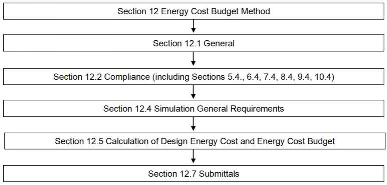
12. ENERGY COST BUDGET METHOD
12.1 General
12.1.1 Energy Cost Budget Method Scope. The building Energy Cost Budget Method is an alternative to the prescriptive provisions of this standard. It may be employed for evaluating the compliance of all pro- posed designs except designs with no mechanical system .
12.1.2 Trade-Offs Limited to Building Permit. When the building permit being sought applies to less than the whole building, only the calculation parameters related to the systems to which the permit applies shall be allowed to vary. Parameters relating to unmodified existing conditions or to future building components shall be identical for both the energy cost budget and the design energy cost calculations. Future build- ing components shall meet the prescriptive requirements of Sections 5.5, 6.5, 7.5, and 9.5.
b. The design energy cost shall comply with the following:
Design Energy Cost Energy Cost Budget 1 - EC------------1000 req - Aadj
where
EC req = energy credits required for the building in accordance with Section 11.5.1
Aadj = where the project includes additions or alterations use an adjustment factor as follows; otherwise use 1.0:
DESIGN SUBMITTED FIRST FOR APPROVAL FROM AHJ… THEN SUBMIT ENERGY COST BUDGET METHOD RESULTS TO AHJ.
Aadj
Addition Gross Floor Area + Alteration Gross Floor Area = ------------------------------------------------------------------------------------------------------------------------------------------Modeled gross floor area
208 ANSI/ASHRAE/IES Standard 90.1-2022 (I-P)
PDF Page 211
Design energy cost = as calculated in Section 12.5 Energy cost budget = as calculated in Section 12.5 c. The energy efficiency level of installed components and systems that meets or exceeds the efficiency lev els used to calculate the design energy cost . d. For new buildings, one of the following is met:
- The building envelope complies with Section 5.5, “Prescriptive Building Envelope Compliance Path.”
- Using Section 5.6, “Building Envelope Trade-Off Compliance Option,” the proposed envelope per- formance factor shall not exceed the base envelope performance factor by more than 15% in multifamily residential, hotel/motel, and dormitory building area types. For all other building area types, the limit shall be 7%. For buildings with both residential and nonresidential occupancies, the limit shall be based on the area-weighted average of the gross conditioned floor area . e. Verification, testing, and commissioning requirements of Section 4.2.5 shall be met. f. Proposed building systems, controls , or building envelope documented in Table 12.7.2(d) that do not have criteria in Sections 5 through 10 shall have verification or testing to document proper installation and operation in accordance with Section 4.2.5. Informative Note: The energy cost budget and the design energy cost calculations are applicable only for determining compliance with this standard. They are not predictions of actual energy consumption or costs of the proposed design after construction . Actual experience will differ from these calculations due to variations such as occupancy, building operation and maintenance, weather, energy use not covered by this standard, changes in energy rates between design of the building and occupancy, and precision of the calculation tool.
12.3 Simplified Option (Not Used)
12.4 Simulation General Requirements 12.4.1 Simulation Program. The simulation program shall be a computer-based program for the analysis of energy consumption in buildings . For components that cannot be modeled by the simulation program, the exceptional calculation methods requirements in Section 12.4.5 shall be used.
Exception to 12.4.1: When approved by the adopting authority, a separate computer-based program shall
be permitted to be used to calculate on-site renewable energy .
Informative Note: ASHRAE Standing Standard Project Committee 90.1 recommends that the simula- tion program implement the rules of Section 12 that control simulation inputs and outputs be adopted for the purposes of easier use and simpler compliance.
12.4.1.1 The simulation program shall be approved by the adopting authority and shall, at a minimum, have the ability to explicitly model all of the following:
a. 8760 hours per year b. Hourly variations in occupancy, lighting power, miscellaneous equipment power, thermostat set points,
humidity set points, and HVAC system operation, defined separately for each day of the week and holidays c. Thermal mass effects d. Ten or more thermal zones e. Part-load performance curves for mechanical equipment f. Capacity and efficiency correction curves for mechanical heating and mechanical cooling equipment g. Air-side economizer and fluid economizer with integrated control h. The budget building design characteristics unless otherwise specified in Section 12.5
12.4.1.2 The simulation program shall have the ability to either
a. directly determine the design energy cost and energy cost budget or b. produce hourly reports of energy use by energy source suitable for determining the design energy cost
and energy cost budget using a separate calculation.
12.4.1.3 The simulation program shall be capable of performing design load calculations to determine required HVAC equipment capacities and air and water flow rates in accordance with Section 6.4.2 for both the proposed design and the budget building design .
12.4.1.4 Simulation Program Testing Requirements 12.4.1.4.1 The simulation program shall be tested according to ASHRAE Standard 140, except for Sections 7 and 8 of Standard 140. The required tests shall include building thermal envelope and fabric load tests (Sections 5.2.1, 5.2.2, and 5.2.3), ground coupled slab-on- grade analytical verification tests (Section 5.2.4),
ANSI/ASHRAE/IES Standard 90.1-2022 (I-P) 209
PDF Page 212
space -cooling equipment performance tests (Section 5.3), space -heating equipment performance tests (Section 5.4), and air-side HVAC equipment analytical verification tests (Section 5.5), along with the associated reporting (Section 6).
12.4.1.4.2 The test results and modeler reports shall be posted on a publicly available website and shall include the test results of the simulation program and input files used for generating results along with the results of the other simulation programs included in ASHRAE Standard 140, Annexes B8 and B16. The modeler report in Standard 140, Annex A2, Attachment A2.7, shall be completed for results exceeding the maximum or falling below the minimum of the reference values and for omitted results.
12.4.1.4.3 The testing shall be performed for the version of the simulation program used to calculate the design energy cost and energy cost budget .
Informative Notes:
- There are no pass/fail criteria established by this requirement.
- Based on the Section 3.2 definition, simulation program includes the simulation engine and the corresponding user interface. The testing of a simulation program only meets the requirements of Section 12.4.1.4 for that simulation program and cannot be used as proxy for documenting compliance of another simulation program that uses the same simulation engine .
12.4.2 Climatic Data. The simulation program shall perform the simulation using hourly values of climatic data, including temperature, humidity, solar radiation, and wind speed and direction from representative climatic data, for the site in which the proposed design is to be located. For locations for which several climatic data sources are available or where weather data are not available, the designer shall select available weather data that best represent the climate at the construction site . The selected weather data shall be approved by the authority having jurisdiction .
12.4.3 Renewable, Recovered, and Purchased Energy
12.4.3.1 On-Site Renewable Energy and Site-Recovered Energy. Site-recovered energy shall not be considered purchased energy and shall be subtracted from the proposed design energy consumption prior to calculating the design energy cost . On-site renewable energy shall be subtracted from the proposed design energy consumption prior to calculating the design energy cost, provided that the building owner
a. owns the on-site renewable energy system, b. has signed a lease agreement for the on-site renewable energy system for at least 15 years, or c. has signed a contractual agreement to purchase energy generated by the on-site renewable energy system
for at least 15 years.
The reduction in design energy cost associated with on-site renewable energy that exceeds the on-site renewable energy required by Section 10.5.1.1 shall be no more than 5% of the calculated energy cost budget .
On-site renewable energy included in the budget building design shall be subtracted from the budget building design energy consumption prior to calculating the energy cost budget.
12.4.3.2 Annual Energy Costs. The design energy cost and energy cost budget shall be determined using rates for purchased energy (such as electricity, gas, oil, propane, steam, and chilled water) that are approved by the adopting authority . Where on-site renewable energy or site-recovered energy is in excess of what is required in the budget building design by Table 12.5.1, the budget building design shall be based on the energy source used as the backup energy source, or electricity if no backup energy source has been specified. Where the proposed design includes on-site electricity generation systems other than on-site renew- able energy systems, the baseline design shall include the same generation systems excluding its site- recovered energy .
12.4.4 Compliance Calculations. The design energy cost and energy cost budget shall be calculated using
a. the same simulation program, b. the same weather data, and c. the same purchased energy rates .
12.4.5 Exceptional Calculation Methods. When the simulation program does not model a design, material, or device, an exceptional calculation method shall be used as approved by the authority having jurisdic- tion to demonstrate compliance with Section 12.
Where there are multiple designs, materials, or devices that the simulation program does not model, each shall be calculated separately and exceptional savings determined for each. All applications for approval of an exceptional method shall include the following:
210 ANSI/ASHRAE/IES Standard 90.1-2022 (I-P)
PDF Page 213
a. Theoretical and empirical information verifying the method’s accuracy, and step-by-step documentation
of the exceptional calculation method performed, detailed enough to reproduce the results. b. Copies of all spreadsheets used to perform the calculations. c. A sensitivity analysis of energy consumption when each of the input parameters that are estimated is var ied from half to double the value assumed. d. The calculations shall be performed on a time-step basis consistent with the simulation program used. e. The energy cost budget and design energy cost calculated with and without the exceptional calculation
methods.
12.5 Calculation of Design Energy Cost and Energy Cost Budget 12.5.1 The simulation model for calculating the design energy cost and the energy cost budget shall be developed in accordance with the requirements in Table 12.5.1.
Exception to 12.5.1: Energy used to recharge or refuel vehicles that are used for off- site transportation
purposes shall not be modeled for the design energy cost or the energy cost budget .
12.5.2 HVAC Systems. The HVAC system type and related performance parameters for the budget build- ing design shall be determined from Figure 12.5.2, the system descriptions in Table 12.5.2-1 and accompanying notes, and the following rules:
a. Budget Building Systems Not Listed. Components and parameters not listed in Figure 12.5.2 and Table
12.5.2-1 or otherwise specifically addressed in this subsection shall be identical to those in the proposed design . Exception to 12.5.2(a): Where there are specific requirements in Sections 6.4 and 6.5, the component
efficiency in the budget building design shall be adjusted to the lowest efficiency level allowed by the requirement for that component type. b. Minimum Equipment Efficiency. All HVAC and service water-heating equipment in the budget build-
ing design shall be modeled at the minimum efficiency levels, both part load and full load, in accordance with Sections 6.4, 6.5.4.8, 7.4, and 7.5 based on the budget system type determined following Section 12.5.2(j) and capacity determined following Section 12.5.2(i). Chillers shall use Path A efficiencies as shown in Table 6.8.1-3 and be modeled using the performance curves specified in Table J-1 and included in Normative Appendix J. When using performance curves from Normative Appendix J, chiller minimum part-load ratio (ratio of load to available capacity at a given simulation time step) and minimum compressor unloading ratio (part-load ratio below which the chiller capacity cannot be reduced by unloading and chiller is false loaded) shall be equal to 0.25. Simulation programs that do not use performance curves are permitted to use an alternative simulation method that results in the same performance as the curves described in Normative Appendix J. c. Supply Fan Energy in Certain Package Equipment. Where efficiency ratings include supply fan
energy, the efficiency rating shall be adjusted to remove the supply fan energy . For budget system Types 3, 4, 6, 8, 9, 10, and 11, calculate the minimum COPnfcooling and COPnfheating using the equation for the applicable performance rating as indicated in Tables 6.8.1-1, 6.8.1-2, 6.8.1-4, and 6.8.1-15. Where a fulland part-load efficiency rating is provided in Tables 6.8.1-1, 6.8.1-2, 6.8.1-4, and 6.8.1-15, the full-load equation below shall be used:
COPnfcooling = 7.84E-8 × EER × Q + 0.338 × EER
COPnfcooling = –0.0076 × SEER [2] + 0.3796 × SEER
(applies to cooling efficiency only) COPnfheating = 1.48E-7 × COP47 × Q + 1.062 × COP47
(applies to Systems 6 and 9 heating efficiency only)
COPnfheating = –0.0296 × HSPF [2] + 0.7134 × HSPF
COPnfcooling = 0.3322 × EER - 0.2145 (applies to Systems 8 and 10 cooling efficiency only)
COPnfheating = 1.1329 × COP - 0.214 (applies to System 8 heating efficiency only)
where COPnfcooling and COPnfheating are the packaged HVAC equipment cooling and heating energy effi- ciency, respectively, to be used in the budget building design, which excludes supply fan power, and Q is the AHRI-rated cooling capacity in Btu/h. If Q is greater than 760,000 Btu/h, use 760,000 Btu/h in the calculation.
ANSI/ASHRAE/IES Standard 90.1-2022 (I-P) 211
PDF Page 214
EER, SEER, COP, and HSPF shall be at AHRI test conditions. Fan energy shall be modeled separately according to Section 12.5.2(h). Supply and return/relief system fans shall be modeled as operating at least whenever the spaces served are occupied, except as specifically noted in Table 12.5.2-1. d. Minimum Outdoor Air Ventilation Rate. Minimum outdoor air ventilation rates shall be the same for
both the budget building design and proposed design . Exhaust air energy recovery shall be modeled for the budget building design in accordance with Section 6.5.6.1. Exceptions to 12.5.2(d):
- When modeling demand control ventilation in the proposed design for spaces where demand con- trol ventilation is not required per Section 6.4.3.8.
- Where the minimum outdoor air intake flow in the proposed design is provided in excess of the amount required by Section 6.5.3.8, the baseline building design shall be modeled to reflect the minimum amount required by Section 6.5.3.8. e. Economizers. All budget building systems as listed in Table 12.5.2-1 shall have air economizers in
accordance with Section 6.5.1 and Section 12.5.2(i). The high-limit shutoff shall be in accordance with Table 12.5.2-4. f. Preheat Coils. If the proposed design system has a preheat coil, the budget building design ’s system shall be modeled with a preheat coil controlled in the same manner. g. Supply Airflow Rates. System design supply air rates for the budget building design shall be based on a
supply-air-to-room temperature set-point difference of 20°F or the minimum outdoor airflow rate, or the airflow rate required to comply with applicable codes or accreditation standards, whichever is greater. For systems with multiple zone thermostat set points, use the design set point that will result in the lowest supply air cooling set point or highest supply air heating set point . If return or relief fans are specified in the proposed design, the budget building design shall also be modeled with fans serving the same functions and sized for the budget system supply fan air quantity less the minimum outdoor air, or 90% of the supply fan air quantity, whichever is larger. Exceptions to 12.5.2(g):
- For systems serving laboratory spaces, airflow rate shall be based on a supply-air-to-room temperature set-point difference of 17°F or the required ventilation air or makeup air, whichever is greater.
- If the proposed design HVAC system airflow rate based on latent loads is greater than the design airflow rate based on sensible loads, then the same supply-air-to-room-air humidity ratio difference (lb) used to calculate the proposed design airflow shall be used to calculate design airflow rates for the budget building design . h. Fan System Efficiency. Fan system efficiency (bhp per cfm of supply air, including the effect of belt
losses but excluding motor and motor drive losses) shall be the same as the proposed design or up to the limit prescribed in Section 6.5.3.1, whichever is smaller. If this limit is reached, each fan shall be proportionally reduced in brake horsepower until the limit is met. Fan electrical power shall then be determined by adjusting the calculated fan hp by the minimum motor efficiency prescribed by Section 10.4.1 for the appropriate motor size for each fan. Exception to 12.5.2(h): When a proposed design includes energy recovery but it is not required in the
budget building design per Section 12.5.2(d), the fan power of those baseline systems shall be equal to either the proposed design system or the fan power limit in Section 6.5.3.1 calculated without fan power credit for energy recovery, whichever is less. i. Equipment Capacities. The equipment capacities for the budget building design shall be sized proportionally to the capacities in the proposed design based on sizing runs, i.e., the ratio between the capacities used in the annual simulations and the capacities determined by the sizing runs shall be the same for both the proposed design and budget building design . Where multiple HVAC zones are combined into a single thermal block or modeled as identical thermal blocks to which multipliers are applied in accordance with Table 12.5.1, the equipment capacities for the budget building design shall be determined as follows:
- For budget system Types 8 and 10, equipment capacity shall be 9000 Btu/h.
- For budget system Types 5, 6, 7, 9, and 11, equipment capacity shall be based on the load of the ther- mal block divided by the number of combined HVAC zones .
- For budget system Types 1, 2, 3, and 4, equipment capacity shall be based on the total load of all associated thermal blocks, including multipliers, divided by the total number of corresponding HVAC systems specified in the design documents.
Unmet load hours for the proposed design or baseline building designs shall not exceed 300 hours (of the 8760 hours simulated). The unmet load hours for the proposed design shall not exceed the unmet
212 ANSI/ASHRAE/IES Standard 90.1-2022 (I-P)
PDF Page 215
load hours for the budget building design . Alternatively, unmet load hours exceeding these limits may be approved by the building official, provided that sufficient justification is given indicating that the accuracy of the simulation is not significantly compromised by these unmet loads. j. Determining the HVAC System. Each HVAC system in a proposed design is mapped on a one-to-one correspondence with one of eleven HVAC systems in the budget building design . To determine the budget building system, do the following:
- Enter Figure 12.5.2 at “Water/Ground” if the proposed design system condenser is water or evaporatively cooled; enter Figure 12.5.2 at “Air/None” if the condenser is air cooled. Closed-circuit dry coolers shall be considered air cooled. Systems utilizing district cooling shall be treated as if the condenser water type were “Water.” If no mechanical cooling is specified or the mechanical cooling sys- tem in the proposed design does not require heat rejection, the system shall be treated as if the condenser water type were “Air.” For proposed designs with ground-source or groundwater-source heat pumps, the budget system shall be water-source heat pump ( System 6).
- Select the path that corresponds to the proposed design heat source: electric resistance, heat pump (including air source and water source), or fuel -fired. Systems utilizing district heating (steam or hot water) shall be treated as if the heating system type were “Fossil Fuel.” Systems with no heating capability shall be treated as if the heating system type were “Fossil Fuel.” For systems with mixed fuel heating sources, the system or systems that use the secondary heating source type (the one with the smallest total installed output capacity for the spaces served by the system ) shall be modeled identically in the budget building design, and the primary heating source type shall be used in Figure 12.5.2 to determine budget system type.
- Select the budget building design system category. The system under “Single-Zone Residential System” shall be selected if the HVAC system in the proposed design is a single-zone system and serves a residential space . The system under “Single-Zone Nonresidential System” shall be selected if the HVAC system in the proposed design is a single-zone system and serves other than residential spaces . The system under “All Other” shall be selected for all other cases. k. Kitchen Exhaust. For kitchens with a total exhaust hood airflow rate greater than 5000 cfm, use a
demand ventilation system on 75% of the exhaust air. The system shall reduce exhaust and replacement air system airflow rates by 50% for one half of the kitchen occupied hours in the baseline building design . If the proposed design uses demand ventilation, the same airflow rate schedule shall be used. The maximum exhaust flow rate allowed for the hood or hood section shall meet the requirements of Section 6.5.7.2.2 for the numbers and types of hoods and appliances provided in the proposed design .
12.5.3 Modeling Building Envelope Air Leakage. The air leakage rate of the building envelope ( I75Pa ) at a pressure differential of 75 Pa (0.30 in. of water) shall be converted to appropriate units for the simulation program using one of the following formulas:
a. For methods describing air leakage as a function of floor area,
IFLR = 0.112 × I75Pa × S/AFLR b. For methods describing air leakage as a function of the area of above-grade walls that separate condi-
tioned spaces and semiheated spaces from the exterior,
IAGW = 0.112 × I75Pa × S/AAGW c. When using the measured air leakage rate of the building envelope at a pressure differential of 75 Pa
(0.30 in. of water) for the proposed design, the air leakage rate shall be calculated as follows:
I75Pa = Q/S
where I75Pa = air leakage rate of the building envelope in cfm/ft [2] at a fixed building pressure differential of 75 Pa (0.30 in. of water) Q = volume of air in cfm flowing through the building envelope when subjected to a pressure differential of 75 Pa (0.30 in. of water), in accordance with ASTM E779, ASTM E1827, or ASTM E3158 S = total area of the building envelope in ft [2], including the lowest floor, any below-grade walls or above-grade walls, and roof (including vertical fenestration and skylights ) IFLR = adjusted air leakage rate of the building envelope cfm/ft [2] at a reference wind speed of 10 mph and relative to the gross floor area AFLR = gross floor area, ft [2]
ANSI/ASHRAE/IES Standard 90.1-2022 (I-P) 213
PDF Page 216
IAGW = adjusted air leakage rate of the building envelope cfm/ft [2] at a reference wind speed of 10 mph and relative to the area of the above-grade walls of the building envelope AAGW = total area of above-grade walls of the building envelope, ft [2]
Exception to 12.5.3: A multizone airflow model alternative method to modeling building envelope air
leakage may be used, provided the following criteria are met:
- Where the calculations are made independently of the energy simulation program, the proposed method must comply with Section 12.4.5.
- The method for converting the air leakage rate of the building envelope at 75 Pa (0.30 in. of water) to the appropriate units for the simulation program is fully documented and submitted to the rating authority for approval.
12.6 Alternative Compliance Path (Not Used)
12.7 Submittals 12.7.1 General. Compliance documentation and supplemental information shall be submitted in accordance with Section 4.2.2 of this standard.
12.7.2 Permit Application Documentation. Compliance shall be documented and submitted to the building official . The information submitted shall include the following:
a. The energy cost budget for the budget building design and the design energy cost for the proposed design . b. The simulation program used and the version of the simulation program . c. An overview of the project that includes the number of stories (above and below grade ), the typical floor
size, the uses in the building (e.g., office, cafeteria, retail, parking, etc.), the gross area of each use, and whether each use is conditioned . d. A list of the energy -related features that are included in the design and on which compliance with the
provisions of Section 12 is based. This list shall document all energy features that differ between the models used in the energy cost budget and the design energy cost calculations. e. A list showing compliance for the proposed design with all the requirements of Sections 5.4, 6.4, 7.4,
8.4, 9.4, and 10.4 (mandatory provisions). f. Building elevations and floor plans. g. A diagram showing the thermal blocks used in the computer simulation. h. An explanation of any significant modeling assumptions. i. Backup calculations and material to support data inputs (e.g., U-factors for building envelope assemblies, NFRC ratings for fenestration, end uses identified in Table 12.5.1(1)(a). j. Reports from the simulation program showing
- a breakdown of energy usage by at least the following components: lights, internal equipment loads, service water-heating equipment, space -heating equipment, space cooling and heat-rejection equip- ment, fans, and other HVAC equipment (such as pumps );
- the amount of time any loads are not met by the HVAC system for both the proposed design and bud- get building design ; and
- a description of energy -related features of the budget building design and the proposed design to support requirements of Section 12.7.2(d). k. Purchased energy rates used in the simulations. l. An explanation of any error messages noted in the simulation program output. m. For any exceptional calculation methods employed, document the predicted energy savings by energy
type, the energy cost savings, a narrative explaining the exceptional calculation method performed, and theoretical or empirical information supporting the accuracy of the method. n. The reduction in design energy cost associated with on-site renewable energy . o. The version of the software and the link to the website that contains the ASHRAE Standard 140 results
for the version used in accordance with Section 12.4.1.4. p. Simulation input files for the budget building design and the proposed design shall be made available if
requested by the building official.
12.7.3 Completion Requirements. Completion requirements shall be in compliance with Sections 5.7.3, 6.7.3, 7.7.3, 8.7.3, 9.7.3, and 10.7.3.
12.8 Product Information (Not Used)
214 ANSI/ASHRAE/IES Standard 90.1-2022 (I-P)
PDF Page 217
Table 12.5.1 Modeling Requirements for Calculating Design Energy Cost and Energy Cost Budget
1. Design Model
2. Additions and Alterations
3. Space Use Classification
4. Schedules
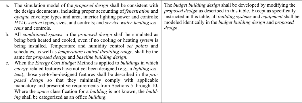
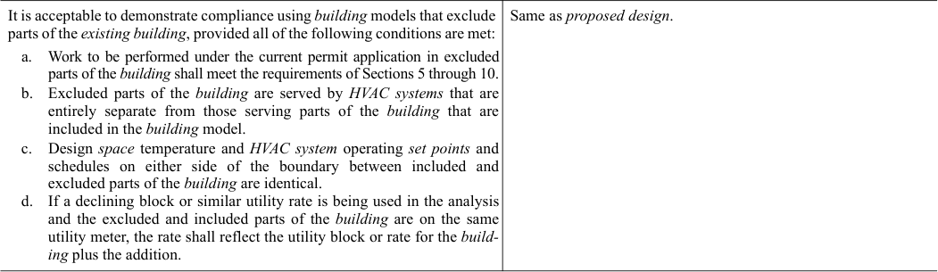

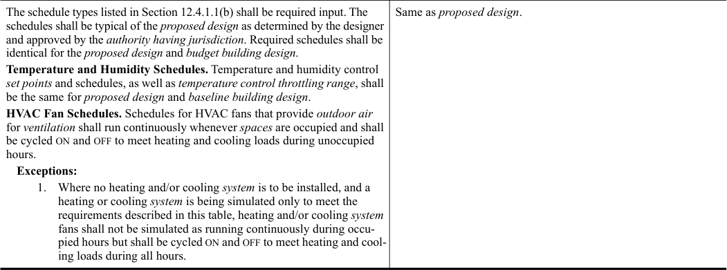
ANSI/ASHRAE/IES Standard 90.1-2022 (I-P) 215
PDF Page 218
Table 12.5.1 Modeling Requirements for Calculating Design Energy Cost and Energy Cost Budget (Continued)
4. Schedules (continued)
5. Building Envelope

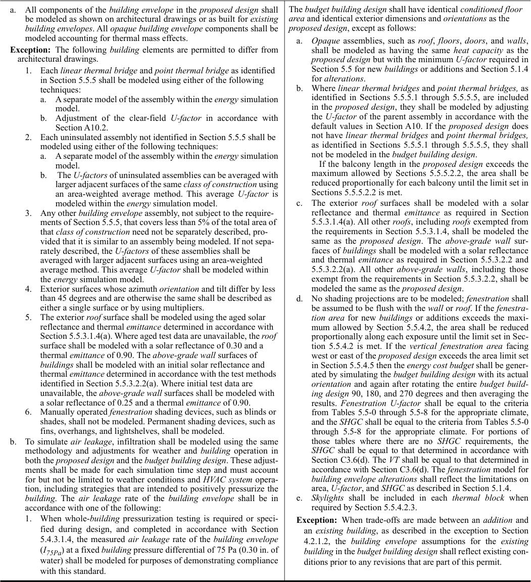
216 ANSI/ASHRAE/IES Standard 90.1-2022 (I-P)
PDF Page 219
Table 12.5.1 Modeling Requirements for Calculating Design Energy Cost and Energy Cost Budget (Continued)
5. Building Envelope (continued)
6. Lighting
7. Thermal Blocks—HVAC Zones Designed

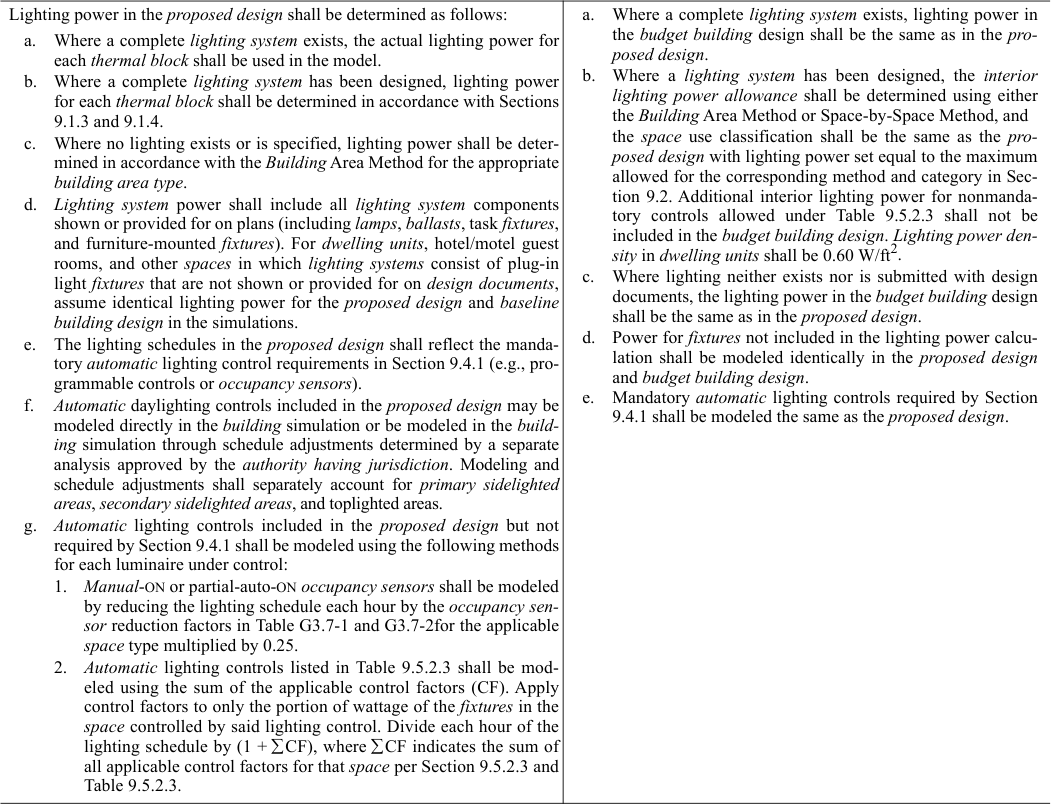
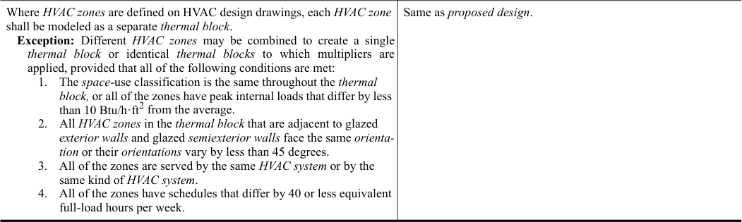
ANSI/ASHRAE/IES Standard 90.1-2022 (I-P) 217
PDF Page 220
Table 12.5.1 Modeling Requirements for Calculating Design Energy Cost and Energy Cost Budget (Continued)
8. Thermal Blocks—HVAC Zones not Designed
9. Thermal Blocks—Multifamily Residential Buildings
10. HVAC Systems
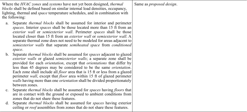

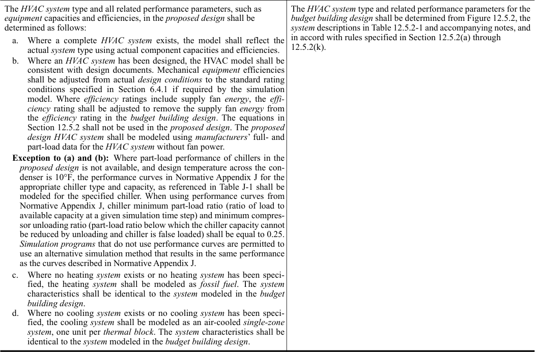
218 ANSI/ASHRAE/IES Standard 90.1-2022 (I-P)
PDF Page 221
Table 12.5.1 Modeling Requirements for Calculating Design Energy Cost and Energy Cost Budget (Continued)
11. Service Water-Heating Systems
12. Miscellaneous Loads
13. Refrigeration
14. Modeling Exceptions
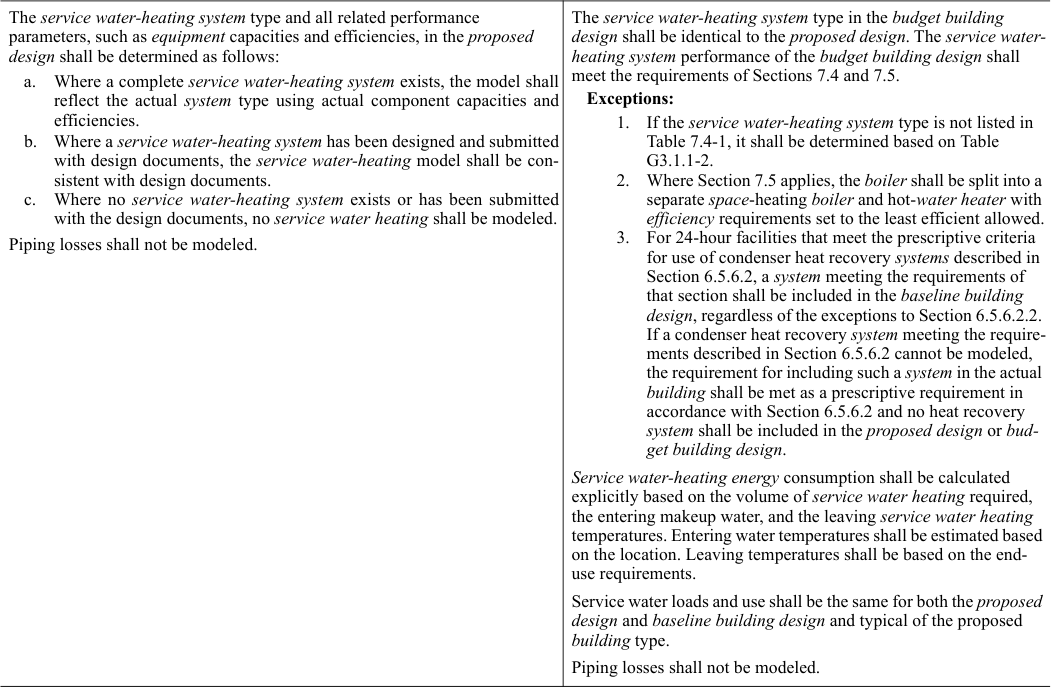
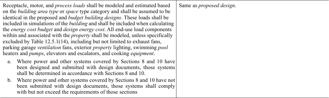

ANSI/ASHRAE/IES Standard 90.1-2022 (I-P) 219
PDF Page 222
Table 12.5.1 Modeling Requirements for Calculating Design Energy Cost and Energy Cost Budget (Continued)
| 14. Modeling Exceptions (continued) | Col2 |
|---|---|
| **Exception:**Components and_systems_ in the_proposed design_ may be excluded from the simulation model provided that 1. component_energy_ use does not affect the_energy_ use of_systems_ and components that are being considered for trade-off and 2. the applicable prescriptive requirements of Sections 5.5, 6.5, 7.5, and 9.5 applying to the excluded components are met. | |
| 15. On-Site Renewable Energy | |
| On-site renewable energy_in the_proposed design shall be determined as follows: a. Where a complete_system_ providing_on-site renewable energy_ exists, the model shall reflect the actual_ system_ type using actual component capaci- ties and efficiencies. b. Where a_system_ providing_on-site renewable energy_has been designed, the_system_ model shall be consistent with design documents. c. Where no_system_ exists or is specified to provide_on-site renewable_ energy, no_system_ shall be modeled. | On-site renewable energy_shall be included in the_budget building design when required by Section 10.5.1, and shall be determined as follows: a. Where a_system_ providing_on-site renewable energy_ has been modeled in the_proposed design_, the same_system_ shall be modeled identically in the_budget building design_, except the rated capacity shall meet the requirements of Section 10.5.1.1. Where more than one type of_on-site renewable_ energy system is modeled, the total capacities shall be allocated in the same proportion as in the_proposed design_. b. Where no_system_ exists or is specified to provide_on-site_ renewable energy in the_proposed design_, on-site renewable energy shall be modeled as an unshaded photovoltaic system with the following physical characteristics: • Size: Rated capacity per Section 10.5.1.1 • Module Type: Crystalline silicon panel with a glass cover, 19.1% nominal efficiency and temperature coefficient of –0.19%/°F; performance shall be based on a reference tem- perature of 77°F and irradiance of 317 Btu/ft2·h. • Array Type: Rack-mounted array with installed nominal operating cell temperature (INOCT) of 103°F • Total system losses (DC output to AC output): 11.3% • Tilt: 0-degrees (mounted horizontally) • Azimuth:180 degrees If the_on-site renewable energy system_ cannot be modeled in the simulation program, Section 12.4.5 shall be used. |
220 ANSI/ASHRAE/IES Standard 90.1-2022 (I-P)
PDF Page 223
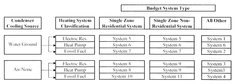
Figure 12.5.2 HVAC systems map.
| Table 12.5.2-1 | Budget System Descriptions | Col3 | Col4 | Col5 |
|---|---|---|---|---|
| System No. | System Type | Fan Control | Cooling Type | Heating Type |
| 1 | VAV with parallel fan-powered boxesa | VAV d | Chilled watere | Electric resistance |
| 2 | VAV with reheatb | VAV d | Chilled watere | Hot-water_fossil fuel_ boilerf |
| 3 | Packaged_VAV_ with parallel fan-powered boxesa | VAV d | Direct expansionc | Electric resistance |
| 4 | Packaged_VAV_ with reheatb | VAV d | Direct expansionc | Hot-water_fossil fuel_ boilerf |
| 5 | Two-pipe fan coil | Single- or two-speed fani,j | Chilled watere | Electric resistance |
| 6 | Water-source heat pump | Single- or two-speed fani,j | Direct expansionc | Electric heat pump and boilerg |
| 7 | Four-pipe fan-coil | Single- or two-speed fani,j | Chilled watere | Hot-water_fossil fuel_ boilerf |
| 8 | Packaged terminal heat pump | Single-speed fani | Direct expansionc | Electric heat pumph |
| 9 | Packaged rooftop heat pump | Single- or two-speed fani,j | Direct expansionc | Electric heat pumph |
| 10 | Packaged terminal air conditioner | Single-speed fani | Direct expansion | Hot-water_fossil fuel_ boilerf |
| 11 | Packaged rooftop air conditioner | Single- or two-speed fani,j | Direct expansion | Fossil fuel furnace |
| a. VAV with Parallel Fan-Powered Boxes: Fans in parallel_VAV_ fan-powered boxes shall be sized for 50% of the peak design flow rate and shall be modeled with 0.35 W/cfm fan power. Minimum volume_set points_ for fan-powered boxes shall be equal to the minimum rate for the_space_ required for_ventilation_ consistent with Section 6.5.2.1, Exception 1(b). Supply air temperature_set point_ shall be constant at the_design condition_ (see Section 12.5.2[g]). b. VAV with Reheat: Minimum volume_set points_ for_VAV_ reheat boxes shall be the larger of the following: (1) the minimum primary outdoor airflow rate required to meet the Simplified Procedure ventilation requirements of ASHRAE Standard 62.1 for the zone or (2) the airflow rate required to comply with applicable codes or accreditation standards, including, but not limited to, pressure relationships or minimum air change rates. The supply air temperature for cooling shall be_reset_ higher by 5°F under the minimum cooling load conditions. c. Direct Expansion: The_fuel_ type for the cooling_system_ shall match that of the cooling_system_ in the_proposed design_. d. VAV: The supply, return, or relief fan motor shall be modeled assuming a variable-speed drive and shall meet the_VAV_ fan part-load performance requirements of Section G3.2.3.15. If the_proposed_ design’s_system_ has a_DDC_ system at the zone level, static pressure_set-point_ reset based on zone requirements in accordance with Section 6.5.3.2.3 shall be modeled. e. Chilled Water: For_systems_ using purchased chilled water, the chillers are not explicitly modeled, and chilled-water costs shall be based as determined in Section 12.4.3. Otherwise, the_budget_ building design’s chiller plant shall be modeled with chillers having the number as indicated in Table 12.5.2-2 as a function of_budget building design_ chiller plant load and type as indicated in Table 12.5.2-3 as a function of individual chiller load. Where chiller_fuel_ source is mixed, the_system_ in the_budget building design_ shall have chillers with the same_fuel_ types and with capacities having the same proportional capacity as the_proposed design_’s chillers for each_fuel_ type. Chilled-water supply temperature shall be modeled at 44°F design supply temperature and 56°F return temperature.Piping losses shall not be modeled in either_building_ model. Chilled-water supply water temperature shall be_reset_ in accordance with Section 6.5.4.4.Pump system power for each pumping_system_ shall be the same as for the_proposed design_; if the_proposed design_ has no chilled-water_pumps_, the_budget building design_ pump power shall be 22 W/gpm (equal to a_pump_ oper- ating against a 75 ft head, 65% combined impeller and motor_efficiency_). The chilled-water_system_ shall be modeled as primary-only variable flow with flow maintained at the design rate through each chiller using a bypass. Chilled-water_pumps_ shall be modeled as riding the_pump_ curve or with variable-speed drives when required in Section 6.5.4.2. The heat-rejection device shall be an open-circuit axial-fan cooling tower with variable-speed fan control, if required in Section 6.5.5, and shall meet the performance requirements of Table 6.8.1-7. Condenser water design supply temperature shall be calculated using the cooling tower approach to the 0.4% evaporation design wet-bulb temperature as generated by the formula below, with a design temperature rise of 10°F: Approach_10°FRange_ = 25.72 – (0.24 × WB) where WB is the 0.4%evaporation design wet-bulb temperature in °F, valid for wet bulbs from 55°F to 90°F. The tower shall be controlled to maintain a cooling tower leaving water temperature, where weather permits, per Table 12.5.2-4, floating up to the design leaving water temperature for the cooling tower.Pump system power for each pumping_system_ shall be the same as the_proposed design_; if the_proposed design_ has no condenser water_pumps_, the_budget building design_ pump power shall be 19 W/gpm (equal to a_pump_ operating against a 60 ft head, 60% combined impeller and motor_efficiency_). Each chiller shall be modeled with separate condenser water and chilled-water_pumps_ interlocked to operate with the associated chiller. f. Fossil Fuel Boiler: For_systems_ using purchased hot water or steam, the_boilers_ are not explicitly modeled and hot-water or steam costs shall be based on actual utility rates. Otherwise, the_boiler_ plant shall use the same_fuel_ as the_proposed design_ and shall be natural draft. The_budget building design_ boiler plant shall be modeled with a single_boiler_ if the_budget building design_ plant load is 600,000 Btu/h or less and with two equally sized_boilers_ for plant capacities exceeding 600,000 Btu/h.Boilers shall be staged as required by the load. For_boiler systems_ meeting the requirements of Section 6.5.4.8, the hot-water supply temperature shall be modeled at 170°F design supply temperature and 120°F return temperature. For all other boiler systems, the hot-water supply tempera- ture shall be modeled at 180°F design supply temperature and 130°F return temperature.Piping losses shall not be modeled in either_building_ model. Hot-water supply water temperature shall be_reset_ in accordance with Section 6.5.4.4.Pump system power for each pumping_system_ shall be the same as for the_proposed design_; if the_proposed design_ has no hot-water_pumps_, the_budget_ building design pump power shall be 19 W/gpm (equal to a_pump_ operating against a 60 ft head, 60% combined impeller and motor_efficiency_). The hot-water_system_ shall be modeled as primary- only with continuous variable flow. Hot-water_pumps_ shall be modeled as riding the_pump_ curve or with variable-speed drives when required by Section 6.5.4.2. g. Electric Heat Pump and Boiler: Water-source heat pumps shall be connected to a common heat-pump water loop controlled to maintain temperatures between 60°F and 90°F. Heat rejection from the loop shall be provided by a closed-circuit axial-fan evaporative fluid cooler with fan-speed control as required in Section 6.5.5.2. Heat addition to the loop shall be provided by a_boiler_ that uses the same_fuel_ as the_proposed design_ and shall be natural draft. If no_boilers_ exist in the_proposed design_, the budget_building_ boilers shall be_fossil fuel_. The_budget building design_ boiler plant shall be modeled with a single_boiler_ if the_budget building design_ plant load is 600,000 Btu/h or less and with two equally sized_boilers_ for plant capacities exceeding 600,000 Btu/h.Boilers shall be staged as required by the load.Piping losses shall not be modeled in either_building_ model.Pump system power shall be the same as for the_proposed design_; if the_proposed design_ has no_pumps_, the_budget building design_ pump power shall be 22 W/gpm, which is equal to a_pump_ operating against a 75 ft head, with a 65% combined impeller and motor_efficiency_. Loop flow shall be variable with flow shutoff at each heat pump when its compressor cyclesOFF as required by Section 6.5.4.5 Loop_pumps_ shall be modeled as riding the_pump_ curve or with variable-speed drives when required by Section 6.5.4.2. h. Electric Heat Pump: Electric air source heat pumps shall be modeled with electric auxiliary heat. The_system_ shall be controlled with a multistage_space_ thermostat and an_outdoor air_ thermostat wired to energize auxiliary heat only on the last_thermostat_ stage and when_outdoor air_ temperature is less than 40°F. i. **Fan System Operation:**Fans shall be controlled in the same manner as in the_proposed design_; i.e., fan operation whenever the_space_ is occupied or fan operation cycledON calls for heating and cooling. j. **Fan Speed Control:**Fans shall operate as one or two speed as required by Section 6.5.3.2, regardless of the fan speed control used in the_proposed_ design. | a. VAV with Parallel Fan-Powered Boxes: Fans in parallel_VAV_ fan-powered boxes shall be sized for 50% of the peak design flow rate and shall be modeled with 0.35 W/cfm fan power. Minimum volume_set points_ for fan-powered boxes shall be equal to the minimum rate for the_space_ required for_ventilation_ consistent with Section 6.5.2.1, Exception 1(b). Supply air temperature_set point_ shall be constant at the_design condition_ (see Section 12.5.2[g]). b. VAV with Reheat: Minimum volume_set points_ for_VAV_ reheat boxes shall be the larger of the following: (1) the minimum primary outdoor airflow rate required to meet the Simplified Procedure ventilation requirements of ASHRAE Standard 62.1 for the zone or (2) the airflow rate required to comply with applicable codes or accreditation standards, including, but not limited to, pressure relationships or minimum air change rates. The supply air temperature for cooling shall be_reset_ higher by 5°F under the minimum cooling load conditions. c. Direct Expansion: The_fuel_ type for the cooling_system_ shall match that of the cooling_system_ in the_proposed design_. d. VAV: The supply, return, or relief fan motor shall be modeled assuming a variable-speed drive and shall meet the_VAV_ fan part-load performance requirements of Section G3.2.3.15. If the_proposed_ design’s_system_ has a_DDC_ system at the zone level, static pressure_set-point_ reset based on zone requirements in accordance with Section 6.5.3.2.3 shall be modeled. e. Chilled Water: For_systems_ using purchased chilled water, the chillers are not explicitly modeled, and chilled-water costs shall be based as determined in Section 12.4.3. Otherwise, the_budget_ building design’s chiller plant shall be modeled with chillers having the number as indicated in Table 12.5.2-2 as a function of_budget building design_ chiller plant load and type as indicated in Table 12.5.2-3 as a function of individual chiller load. Where chiller_fuel_ source is mixed, the_system_ in the_budget building design_ shall have chillers with the same_fuel_ types and with capacities having the same proportional capacity as the_proposed design_’s chillers for each_fuel_ type. Chilled-water supply temperature shall be modeled at 44°F design supply temperature and 56°F return temperature.Piping losses shall not be modeled in either_building_ model. Chilled-water supply water temperature shall be_reset_ in accordance with Section 6.5.4.4.Pump system power for each pumping_system_ shall be the same as for the_proposed design_; if the_proposed design_ has no chilled-water_pumps_, the_budget building design_ pump power shall be 22 W/gpm (equal to a_pump_ oper- ating against a 75 ft head, 65% combined impeller and motor_efficiency_). The chilled-water_system_ shall be modeled as primary-only variable flow with flow maintained at the design rate through each chiller using a bypass. Chilled-water_pumps_ shall be modeled as riding the_pump_ curve or with variable-speed drives when required in Section 6.5.4.2. The heat-rejection device shall be an open-circuit axial-fan cooling tower with variable-speed fan control, if required in Section 6.5.5, and shall meet the performance requirements of Table 6.8.1-7. Condenser water design supply temperature shall be calculated using the cooling tower approach to the 0.4% evaporation design wet-bulb temperature as generated by the formula below, with a design temperature rise of 10°F: Approach_10°FRange_ = 25.72 – (0.24 × WB) where WB is the 0.4%evaporation design wet-bulb temperature in °F, valid for wet bulbs from 55°F to 90°F. The tower shall be controlled to maintain a cooling tower leaving water temperature, where weather permits, per Table 12.5.2-4, floating up to the design leaving water temperature for the cooling tower.Pump system power for each pumping_system_ shall be the same as the_proposed design_; if the_proposed design_ has no condenser water_pumps_, the_budget building design_ pump power shall be 19 W/gpm (equal to a_pump_ operating against a 60 ft head, 60% combined impeller and motor_efficiency_). Each chiller shall be modeled with separate condenser water and chilled-water_pumps_ interlocked to operate with the associated chiller. f. Fossil Fuel Boiler: For_systems_ using purchased hot water or steam, the_boilers_ are not explicitly modeled and hot-water or steam costs shall be based on actual utility rates. Otherwise, the_boiler_ plant shall use the same_fuel_ as the_proposed design_ and shall be natural draft. The_budget building design_ boiler plant shall be modeled with a single_boiler_ if the_budget building design_ plant load is 600,000 Btu/h or less and with two equally sized_boilers_ for plant capacities exceeding 600,000 Btu/h.Boilers shall be staged as required by the load. For_boiler systems_ meeting the requirements of Section 6.5.4.8, the hot-water supply temperature shall be modeled at 170°F design supply temperature and 120°F return temperature. For all other boiler systems, the hot-water supply tempera- ture shall be modeled at 180°F design supply temperature and 130°F return temperature.Piping losses shall not be modeled in either_building_ model. Hot-water supply water temperature shall be_reset_ in accordance with Section 6.5.4.4.Pump system power for each pumping_system_ shall be the same as for the_proposed design_; if the_proposed design_ has no hot-water_pumps_, the_budget_ building design pump power shall be 19 W/gpm (equal to a_pump_ operating against a 60 ft head, 60% combined impeller and motor_efficiency_). The hot-water_system_ shall be modeled as primary- only with continuous variable flow. Hot-water_pumps_ shall be modeled as riding the_pump_ curve or with variable-speed drives when required by Section 6.5.4.2. g. Electric Heat Pump and Boiler: Water-source heat pumps shall be connected to a common heat-pump water loop controlled to maintain temperatures between 60°F and 90°F. Heat rejection from the loop shall be provided by a closed-circuit axial-fan evaporative fluid cooler with fan-speed control as required in Section 6.5.5.2. Heat addition to the loop shall be provided by a_boiler_ that uses the same_fuel_ as the_proposed design_ and shall be natural draft. If no_boilers_ exist in the_proposed design_, the budget_building_ boilers shall be_fossil fuel_. The_budget building design_ boiler plant shall be modeled with a single_boiler_ if the_budget building design_ plant load is 600,000 Btu/h or less and with two equally sized_boilers_ for plant capacities exceeding 600,000 Btu/h.Boilers shall be staged as required by the load.Piping losses shall not be modeled in either_building_ model.Pump system power shall be the same as for the_proposed design_; if the_proposed design_ has no_pumps_, the_budget building design_ pump power shall be 22 W/gpm, which is equal to a_pump_ operating against a 75 ft head, with a 65% combined impeller and motor_efficiency_. Loop flow shall be variable with flow shutoff at each heat pump when its compressor cyclesOFF as required by Section 6.5.4.5 Loop_pumps_ shall be modeled as riding the_pump_ curve or with variable-speed drives when required by Section 6.5.4.2. h. Electric Heat Pump: Electric air source heat pumps shall be modeled with electric auxiliary heat. The_system_ shall be controlled with a multistage_space_ thermostat and an_outdoor air_ thermostat wired to energize auxiliary heat only on the last_thermostat_ stage and when_outdoor air_ temperature is less than 40°F. i. **Fan System Operation:**Fans shall be controlled in the same manner as in the_proposed design_; i.e., fan operation whenever the_space_ is occupied or fan operation cycledON calls for heating and cooling. j. **Fan Speed Control:**Fans shall operate as one or two speed as required by Section 6.5.3.2, regardless of the fan speed control used in the_proposed_ design. | a. VAV with Parallel Fan-Powered Boxes: Fans in parallel_VAV_ fan-powered boxes shall be sized for 50% of the peak design flow rate and shall be modeled with 0.35 W/cfm fan power. Minimum volume_set points_ for fan-powered boxes shall be equal to the minimum rate for the_space_ required for_ventilation_ consistent with Section 6.5.2.1, Exception 1(b). Supply air temperature_set point_ shall be constant at the_design condition_ (see Section 12.5.2[g]). b. VAV with Reheat: Minimum volume_set points_ for_VAV_ reheat boxes shall be the larger of the following: (1) the minimum primary outdoor airflow rate required to meet the Simplified Procedure ventilation requirements of ASHRAE Standard 62.1 for the zone or (2) the airflow rate required to comply with applicable codes or accreditation standards, including, but not limited to, pressure relationships or minimum air change rates. The supply air temperature for cooling shall be_reset_ higher by 5°F under the minimum cooling load conditions. c. Direct Expansion: The_fuel_ type for the cooling_system_ shall match that of the cooling_system_ in the_proposed design_. d. VAV: The supply, return, or relief fan motor shall be modeled assuming a variable-speed drive and shall meet the_VAV_ fan part-load performance requirements of Section G3.2.3.15. If the_proposed_ design’s_system_ has a_DDC_ system at the zone level, static pressure_set-point_ reset based on zone requirements in accordance with Section 6.5.3.2.3 shall be modeled. e. Chilled Water: For_systems_ using purchased chilled water, the chillers are not explicitly modeled, and chilled-water costs shall be based as determined in Section 12.4.3. Otherwise, the_budget_ building design’s chiller plant shall be modeled with chillers having the number as indicated in Table 12.5.2-2 as a function of_budget building design_ chiller plant load and type as indicated in Table 12.5.2-3 as a function of individual chiller load. Where chiller_fuel_ source is mixed, the_system_ in the_budget building design_ shall have chillers with the same_fuel_ types and with capacities having the same proportional capacity as the_proposed design_’s chillers for each_fuel_ type. Chilled-water supply temperature shall be modeled at 44°F design supply temperature and 56°F return temperature.Piping losses shall not be modeled in either_building_ model. Chilled-water supply water temperature shall be_reset_ in accordance with Section 6.5.4.4.Pump system power for each pumping_system_ shall be the same as for the_proposed design_; if the_proposed design_ has no chilled-water_pumps_, the_budget building design_ pump power shall be 22 W/gpm (equal to a_pump_ oper- ating against a 75 ft head, 65% combined impeller and motor_efficiency_). The chilled-water_system_ shall be modeled as primary-only variable flow with flow maintained at the design rate through each chiller using a bypass. Chilled-water_pumps_ shall be modeled as riding the_pump_ curve or with variable-speed drives when required in Section 6.5.4.2. The heat-rejection device shall be an open-circuit axial-fan cooling tower with variable-speed fan control, if required in Section 6.5.5, and shall meet the performance requirements of Table 6.8.1-7. Condenser water design supply temperature shall be calculated using the cooling tower approach to the 0.4% evaporation design wet-bulb temperature as generated by the formula below, with a design temperature rise of 10°F: Approach_10°FRange_ = 25.72 – (0.24 × WB) where WB is the 0.4%evaporation design wet-bulb temperature in °F, valid for wet bulbs from 55°F to 90°F. The tower shall be controlled to maintain a cooling tower leaving water temperature, where weather permits, per Table 12.5.2-4, floating up to the design leaving water temperature for the cooling tower.Pump system power for each pumping_system_ shall be the same as the_proposed design_; if the_proposed design_ has no condenser water_pumps_, the_budget building design_ pump power shall be 19 W/gpm (equal to a_pump_ operating against a 60 ft head, 60% combined impeller and motor_efficiency_). Each chiller shall be modeled with separate condenser water and chilled-water_pumps_ interlocked to operate with the associated chiller. f. Fossil Fuel Boiler: For_systems_ using purchased hot water or steam, the_boilers_ are not explicitly modeled and hot-water or steam costs shall be based on actual utility rates. Otherwise, the_boiler_ plant shall use the same_fuel_ as the_proposed design_ and shall be natural draft. The_budget building design_ boiler plant shall be modeled with a single_boiler_ if the_budget building design_ plant load is 600,000 Btu/h or less and with two equally sized_boilers_ for plant capacities exceeding 600,000 Btu/h.Boilers shall be staged as required by the load. For_boiler systems_ meeting the requirements of Section 6.5.4.8, the hot-water supply temperature shall be modeled at 170°F design supply temperature and 120°F return temperature. For all other boiler systems, the hot-water supply tempera- ture shall be modeled at 180°F design supply temperature and 130°F return temperature.Piping losses shall not be modeled in either_building_ model. Hot-water supply water temperature shall be_reset_ in accordance with Section 6.5.4.4.Pump system power for each pumping_system_ shall be the same as for the_proposed design_; if the_proposed design_ has no hot-water_pumps_, the_budget_ building design pump power shall be 19 W/gpm (equal to a_pump_ operating against a 60 ft head, 60% combined impeller and motor_efficiency_). The hot-water_system_ shall be modeled as primary- only with continuous variable flow. Hot-water_pumps_ shall be modeled as riding the_pump_ curve or with variable-speed drives when required by Section 6.5.4.2. g. Electric Heat Pump and Boiler: Water-source heat pumps shall be connected to a common heat-pump water loop controlled to maintain temperatures between 60°F and 90°F. Heat rejection from the loop shall be provided by a closed-circuit axial-fan evaporative fluid cooler with fan-speed control as required in Section 6.5.5.2. Heat addition to the loop shall be provided by a_boiler_ that uses the same_fuel_ as the_proposed design_ and shall be natural draft. If no_boilers_ exist in the_proposed design_, the budget_building_ boilers shall be_fossil fuel_. The_budget building design_ boiler plant shall be modeled with a single_boiler_ if the_budget building design_ plant load is 600,000 Btu/h or less and with two equally sized_boilers_ for plant capacities exceeding 600,000 Btu/h.Boilers shall be staged as required by the load.Piping losses shall not be modeled in either_building_ model.Pump system power shall be the same as for the_proposed design_; if the_proposed design_ has no_pumps_, the_budget building design_ pump power shall be 22 W/gpm, which is equal to a_pump_ operating against a 75 ft head, with a 65% combined impeller and motor_efficiency_. Loop flow shall be variable with flow shutoff at each heat pump when its compressor cyclesOFF as required by Section 6.5.4.5 Loop_pumps_ shall be modeled as riding the_pump_ curve or with variable-speed drives when required by Section 6.5.4.2. h. Electric Heat Pump: Electric air source heat pumps shall be modeled with electric auxiliary heat. The_system_ shall be controlled with a multistage_space_ thermostat and an_outdoor air_ thermostat wired to energize auxiliary heat only on the last_thermostat_ stage and when_outdoor air_ temperature is less than 40°F. i. **Fan System Operation:**Fans shall be controlled in the same manner as in the_proposed design_; i.e., fan operation whenever the_space_ is occupied or fan operation cycledON calls for heating and cooling. j. **Fan Speed Control:**Fans shall operate as one or two speed as required by Section 6.5.3.2, regardless of the fan speed control used in the_proposed_ design. | a. VAV with Parallel Fan-Powered Boxes: Fans in parallel_VAV_ fan-powered boxes shall be sized for 50% of the peak design flow rate and shall be modeled with 0.35 W/cfm fan power. Minimum volume_set points_ for fan-powered boxes shall be equal to the minimum rate for the_space_ required for_ventilation_ consistent with Section 6.5.2.1, Exception 1(b). Supply air temperature_set point_ shall be constant at the_design condition_ (see Section 12.5.2[g]). b. VAV with Reheat: Minimum volume_set points_ for_VAV_ reheat boxes shall be the larger of the following: (1) the minimum primary outdoor airflow rate required to meet the Simplified Procedure ventilation requirements of ASHRAE Standard 62.1 for the zone or (2) the airflow rate required to comply with applicable codes or accreditation standards, including, but not limited to, pressure relationships or minimum air change rates. The supply air temperature for cooling shall be_reset_ higher by 5°F under the minimum cooling load conditions. c. Direct Expansion: The_fuel_ type for the cooling_system_ shall match that of the cooling_system_ in the_proposed design_. d. VAV: The supply, return, or relief fan motor shall be modeled assuming a variable-speed drive and shall meet the_VAV_ fan part-load performance requirements of Section G3.2.3.15. If the_proposed_ design’s_system_ has a_DDC_ system at the zone level, static pressure_set-point_ reset based on zone requirements in accordance with Section 6.5.3.2.3 shall be modeled. e. Chilled Water: For_systems_ using purchased chilled water, the chillers are not explicitly modeled, and chilled-water costs shall be based as determined in Section 12.4.3. Otherwise, the_budget_ building design’s chiller plant shall be modeled with chillers having the number as indicated in Table 12.5.2-2 as a function of_budget building design_ chiller plant load and type as indicated in Table 12.5.2-3 as a function of individual chiller load. Where chiller_fuel_ source is mixed, the_system_ in the_budget building design_ shall have chillers with the same_fuel_ types and with capacities having the same proportional capacity as the_proposed design_’s chillers for each_fuel_ type. Chilled-water supply temperature shall be modeled at 44°F design supply temperature and 56°F return temperature.Piping losses shall not be modeled in either_building_ model. Chilled-water supply water temperature shall be_reset_ in accordance with Section 6.5.4.4.Pump system power for each pumping_system_ shall be the same as for the_proposed design_; if the_proposed design_ has no chilled-water_pumps_, the_budget building design_ pump power shall be 22 W/gpm (equal to a_pump_ oper- ating against a 75 ft head, 65% combined impeller and motor_efficiency_). The chilled-water_system_ shall be modeled as primary-only variable flow with flow maintained at the design rate through each chiller using a bypass. Chilled-water_pumps_ shall be modeled as riding the_pump_ curve or with variable-speed drives when required in Section 6.5.4.2. The heat-rejection device shall be an open-circuit axial-fan cooling tower with variable-speed fan control, if required in Section 6.5.5, and shall meet the performance requirements of Table 6.8.1-7. Condenser water design supply temperature shall be calculated using the cooling tower approach to the 0.4% evaporation design wet-bulb temperature as generated by the formula below, with a design temperature rise of 10°F: Approach_10°FRange_ = 25.72 – (0.24 × WB) where WB is the 0.4%evaporation design wet-bulb temperature in °F, valid for wet bulbs from 55°F to 90°F. The tower shall be controlled to maintain a cooling tower leaving water temperature, where weather permits, per Table 12.5.2-4, floating up to the design leaving water temperature for the cooling tower.Pump system power for each pumping_system_ shall be the same as the_proposed design_; if the_proposed design_ has no condenser water_pumps_, the_budget building design_ pump power shall be 19 W/gpm (equal to a_pump_ operating against a 60 ft head, 60% combined impeller and motor_efficiency_). Each chiller shall be modeled with separate condenser water and chilled-water_pumps_ interlocked to operate with the associated chiller. f. Fossil Fuel Boiler: For_systems_ using purchased hot water or steam, the_boilers_ are not explicitly modeled and hot-water or steam costs shall be based on actual utility rates. Otherwise, the_boiler_ plant shall use the same_fuel_ as the_proposed design_ and shall be natural draft. The_budget building design_ boiler plant shall be modeled with a single_boiler_ if the_budget building design_ plant load is 600,000 Btu/h or less and with two equally sized_boilers_ for plant capacities exceeding 600,000 Btu/h.Boilers shall be staged as required by the load. For_boiler systems_ meeting the requirements of Section 6.5.4.8, the hot-water supply temperature shall be modeled at 170°F design supply temperature and 120°F return temperature. For all other boiler systems, the hot-water supply tempera- ture shall be modeled at 180°F design supply temperature and 130°F return temperature.Piping losses shall not be modeled in either_building_ model. Hot-water supply water temperature shall be_reset_ in accordance with Section 6.5.4.4.Pump system power for each pumping_system_ shall be the same as for the_proposed design_; if the_proposed design_ has no hot-water_pumps_, the_budget_ building design pump power shall be 19 W/gpm (equal to a_pump_ operating against a 60 ft head, 60% combined impeller and motor_efficiency_). The hot-water_system_ shall be modeled as primary- only with continuous variable flow. Hot-water_pumps_ shall be modeled as riding the_pump_ curve or with variable-speed drives when required by Section 6.5.4.2. g. Electric Heat Pump and Boiler: Water-source heat pumps shall be connected to a common heat-pump water loop controlled to maintain temperatures between 60°F and 90°F. Heat rejection from the loop shall be provided by a closed-circuit axial-fan evaporative fluid cooler with fan-speed control as required in Section 6.5.5.2. Heat addition to the loop shall be provided by a_boiler_ that uses the same_fuel_ as the_proposed design_ and shall be natural draft. If no_boilers_ exist in the_proposed design_, the budget_building_ boilers shall be_fossil fuel_. The_budget building design_ boiler plant shall be modeled with a single_boiler_ if the_budget building design_ plant load is 600,000 Btu/h or less and with two equally sized_boilers_ for plant capacities exceeding 600,000 Btu/h.Boilers shall be staged as required by the load.Piping losses shall not be modeled in either_building_ model.Pump system power shall be the same as for the_proposed design_; if the_proposed design_ has no_pumps_, the_budget building design_ pump power shall be 22 W/gpm, which is equal to a_pump_ operating against a 75 ft head, with a 65% combined impeller and motor_efficiency_. Loop flow shall be variable with flow shutoff at each heat pump when its compressor cyclesOFF as required by Section 6.5.4.5 Loop_pumps_ shall be modeled as riding the_pump_ curve or with variable-speed drives when required by Section 6.5.4.2. h. Electric Heat Pump: Electric air source heat pumps shall be modeled with electric auxiliary heat. The_system_ shall be controlled with a multistage_space_ thermostat and an_outdoor air_ thermostat wired to energize auxiliary heat only on the last_thermostat_ stage and when_outdoor air_ temperature is less than 40°F. i. **Fan System Operation:**Fans shall be controlled in the same manner as in the_proposed design_; i.e., fan operation whenever the_space_ is occupied or fan operation cycledON calls for heating and cooling. j. **Fan Speed Control:**Fans shall operate as one or two speed as required by Section 6.5.3.2, regardless of the fan speed control used in the_proposed_ design. | a. VAV with Parallel Fan-Powered Boxes: Fans in parallel_VAV_ fan-powered boxes shall be sized for 50% of the peak design flow rate and shall be modeled with 0.35 W/cfm fan power. Minimum volume_set points_ for fan-powered boxes shall be equal to the minimum rate for the_space_ required for_ventilation_ consistent with Section 6.5.2.1, Exception 1(b). Supply air temperature_set point_ shall be constant at the_design condition_ (see Section 12.5.2[g]). b. VAV with Reheat: Minimum volume_set points_ for_VAV_ reheat boxes shall be the larger of the following: (1) the minimum primary outdoor airflow rate required to meet the Simplified Procedure ventilation requirements of ASHRAE Standard 62.1 for the zone or (2) the airflow rate required to comply with applicable codes or accreditation standards, including, but not limited to, pressure relationships or minimum air change rates. The supply air temperature for cooling shall be_reset_ higher by 5°F under the minimum cooling load conditions. c. Direct Expansion: The_fuel_ type for the cooling_system_ shall match that of the cooling_system_ in the_proposed design_. d. VAV: The supply, return, or relief fan motor shall be modeled assuming a variable-speed drive and shall meet the_VAV_ fan part-load performance requirements of Section G3.2.3.15. If the_proposed_ design’s_system_ has a_DDC_ system at the zone level, static pressure_set-point_ reset based on zone requirements in accordance with Section 6.5.3.2.3 shall be modeled. e. Chilled Water: For_systems_ using purchased chilled water, the chillers are not explicitly modeled, and chilled-water costs shall be based as determined in Section 12.4.3. Otherwise, the_budget_ building design’s chiller plant shall be modeled with chillers having the number as indicated in Table 12.5.2-2 as a function of_budget building design_ chiller plant load and type as indicated in Table 12.5.2-3 as a function of individual chiller load. Where chiller_fuel_ source is mixed, the_system_ in the_budget building design_ shall have chillers with the same_fuel_ types and with capacities having the same proportional capacity as the_proposed design_’s chillers for each_fuel_ type. Chilled-water supply temperature shall be modeled at 44°F design supply temperature and 56°F return temperature.Piping losses shall not be modeled in either_building_ model. Chilled-water supply water temperature shall be_reset_ in accordance with Section 6.5.4.4.Pump system power for each pumping_system_ shall be the same as for the_proposed design_; if the_proposed design_ has no chilled-water_pumps_, the_budget building design_ pump power shall be 22 W/gpm (equal to a_pump_ oper- ating against a 75 ft head, 65% combined impeller and motor_efficiency_). The chilled-water_system_ shall be modeled as primary-only variable flow with flow maintained at the design rate through each chiller using a bypass. Chilled-water_pumps_ shall be modeled as riding the_pump_ curve or with variable-speed drives when required in Section 6.5.4.2. The heat-rejection device shall be an open-circuit axial-fan cooling tower with variable-speed fan control, if required in Section 6.5.5, and shall meet the performance requirements of Table 6.8.1-7. Condenser water design supply temperature shall be calculated using the cooling tower approach to the 0.4% evaporation design wet-bulb temperature as generated by the formula below, with a design temperature rise of 10°F: Approach_10°FRange_ = 25.72 – (0.24 × WB) where WB is the 0.4%evaporation design wet-bulb temperature in °F, valid for wet bulbs from 55°F to 90°F. The tower shall be controlled to maintain a cooling tower leaving water temperature, where weather permits, per Table 12.5.2-4, floating up to the design leaving water temperature for the cooling tower.Pump system power for each pumping_system_ shall be the same as the_proposed design_; if the_proposed design_ has no condenser water_pumps_, the_budget building design_ pump power shall be 19 W/gpm (equal to a_pump_ operating against a 60 ft head, 60% combined impeller and motor_efficiency_). Each chiller shall be modeled with separate condenser water and chilled-water_pumps_ interlocked to operate with the associated chiller. f. Fossil Fuel Boiler: For_systems_ using purchased hot water or steam, the_boilers_ are not explicitly modeled and hot-water or steam costs shall be based on actual utility rates. Otherwise, the_boiler_ plant shall use the same_fuel_ as the_proposed design_ and shall be natural draft. The_budget building design_ boiler plant shall be modeled with a single_boiler_ if the_budget building design_ plant load is 600,000 Btu/h or less and with two equally sized_boilers_ for plant capacities exceeding 600,000 Btu/h.Boilers shall be staged as required by the load. For_boiler systems_ meeting the requirements of Section 6.5.4.8, the hot-water supply temperature shall be modeled at 170°F design supply temperature and 120°F return temperature. For all other boiler systems, the hot-water supply tempera- ture shall be modeled at 180°F design supply temperature and 130°F return temperature.Piping losses shall not be modeled in either_building_ model. Hot-water supply water temperature shall be_reset_ in accordance with Section 6.5.4.4.Pump system power for each pumping_system_ shall be the same as for the_proposed design_; if the_proposed design_ has no hot-water_pumps_, the_budget_ building design pump power shall be 19 W/gpm (equal to a_pump_ operating against a 60 ft head, 60% combined impeller and motor_efficiency_). The hot-water_system_ shall be modeled as primary- only with continuous variable flow. Hot-water_pumps_ shall be modeled as riding the_pump_ curve or with variable-speed drives when required by Section 6.5.4.2. g. Electric Heat Pump and Boiler: Water-source heat pumps shall be connected to a common heat-pump water loop controlled to maintain temperatures between 60°F and 90°F. Heat rejection from the loop shall be provided by a closed-circuit axial-fan evaporative fluid cooler with fan-speed control as required in Section 6.5.5.2. Heat addition to the loop shall be provided by a_boiler_ that uses the same_fuel_ as the_proposed design_ and shall be natural draft. If no_boilers_ exist in the_proposed design_, the budget_building_ boilers shall be_fossil fuel_. The_budget building design_ boiler plant shall be modeled with a single_boiler_ if the_budget building design_ plant load is 600,000 Btu/h or less and with two equally sized_boilers_ for plant capacities exceeding 600,000 Btu/h.Boilers shall be staged as required by the load.Piping losses shall not be modeled in either_building_ model.Pump system power shall be the same as for the_proposed design_; if the_proposed design_ has no_pumps_, the_budget building design_ pump power shall be 22 W/gpm, which is equal to a_pump_ operating against a 75 ft head, with a 65% combined impeller and motor_efficiency_. Loop flow shall be variable with flow shutoff at each heat pump when its compressor cyclesOFF as required by Section 6.5.4.5 Loop_pumps_ shall be modeled as riding the_pump_ curve or with variable-speed drives when required by Section 6.5.4.2. h. Electric Heat Pump: Electric air source heat pumps shall be modeled with electric auxiliary heat. The_system_ shall be controlled with a multistage_space_ thermostat and an_outdoor air_ thermostat wired to energize auxiliary heat only on the last_thermostat_ stage and when_outdoor air_ temperature is less than 40°F. i. **Fan System Operation:**Fans shall be controlled in the same manner as in the_proposed design_; i.e., fan operation whenever the_space_ is occupied or fan operation cycledON calls for heating and cooling. j. **Fan Speed Control:**Fans shall operate as one or two speed as required by Section 6.5.3.2, regardless of the fan speed control used in the_proposed_ design. |
ANSI/ASHRAE/IES Standard 90.1-2022 (I-P) 221
PDF Page 224
Table 12.5.2-2 Number of Chillers
Table 12.5.2-3 Water Chiller Types
Table 12.5.2-4 Cooling Tower Leaving Water Temperature
222 ANSI/ASHRAE/IES Standard 90.1-2022 (I-P)


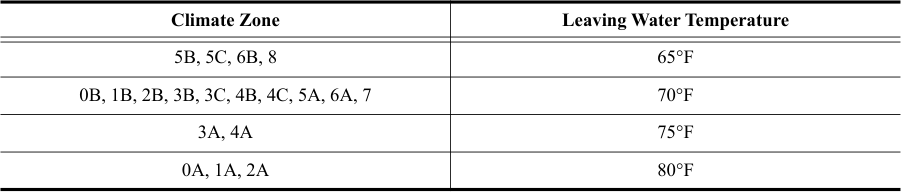
PDF Page 225
13. NORMATIVE REFERENCES
Reference Section
Air Conditioning, Heating and Refrigeration Institute (AHRI) 2311 Wilson Blvd., Arlington, VA 22201
AHRI 210/240 (2017) with addendum 1 Unitary Air Conditioning and Air-Source Heat Pump Equipment (applicable before 1/1/2023)
AHRI 210/240-2023 (2020) Unitary Air Conditioning and Air-Source Heat Pump Equipment (applicable on or after 1/1/2023)
Table 6.8.1-1, Table 6.8.1-2,
Table F-1, Table G3.5.1,
Table G3.5.2
Table 6.8.1-1, Table 6.8.1-8, Table 6.8.1-9,
Table F-1
AHRI 310/380 (2017) Packaged Terminal Air-Conditioners and Heat Pumps Table 6.8.1-4,
Table G3.5.4
AHRI 340/360 (I-P/2022) Performance Rating of Commercial and Industrial Unitary Air-Conditioning and Heat Pump Equipment
ANSI/AHRI 365 (I-P/2009) Commercial and Industrial Unitary Air-Conditioning Condensing Units
AHRI 390 (I-P/2021) Performance Rating of Single Packaged Vertical Air-Conditioners and Heat Pumps
Table 6.8.1-1, Table 6.8.1-2,
Table G3.5.1,
Table G3.5.2
Table 6.8.1-1
Table 6.8.1-4
ANSI/AHRI 400 (I-P/2015) Performance Rating of Liquid-to-Liquid Heat Exchangers 6.4.7
ANSI/AHRI 460 (2005) Remote Mechanical Draft Air Cooled Refrigerant Condensers Table 6.8.1-7
AHRI 550/590 (I-P/2020) (with Addendum 1)
Performance Rating of Water-Chilling and Heat-Pump Water-Heating Packages Using the Vapor Compression Cycle
6.4.1.2.1, 6.4.1.2.2.1, 6.4.1.2.2.2, 6.4.1.2.2.3, 6.4.1.2.2.4, Table 6.8.1-3, Table 6.8.1-16,
Table G3.5.3
AHRI 560 (2000) Absorption Water Chilling and Water Heating Packages Table 6.8.1-3
ANSI/AHRI 910 (I-P/2014) Performance Rating of Indoor Pool Dehumidifiers Table 6.8.1-12
ANSI/AHRI 920 (I-P/2015) Performance Rating of DX-Dedicated Outdoor Air System Units 3.2, Table 6.8.1-13, Table 6.8.1-14
ANSI/AHRI 1200 (I-P/2013) Performance Rating of Commercial Refrigerated Display Merchandisers and Storage Cabinets
ANSI/AHRI 1230 (I-P/2014) (with Addendum 1)
Performance Rating of Variable Refrigerant Flow (VRF) Multi-Split Air-Conditioning and Heat Pump Equipment
Table 6.8.1-11,
Table 12.5.1,
Table G3.1, Table G3.10.1,
Table G3.10.2
Table 6.8.1-8,
Table 6.8.1-9
Table 6.8.1-8,
Table 6.8.1-9
ANSI/AHRI 1230 (I-P/2021) Performance Rating of Variable Refrigerant Flow (VRF) Multi-Split Air-Conditioning and Heat Pump Equipment
AHRI Standard 1250 (I-P/2020) Performance Rating of Walk-In Coolers and Freezers Table 6.8.1-20
AHRI Standard 1300 (I-P/2013) Performance Rating of Commercial Heat Pump Water Heaters 11.5.2.3.1
AHRI Standard 1360 (I-P/2017) Performance Rating of Computer and Data Processing Room Air Conditioners
Table 6.8.1-10,
Table 6.8.1-17
ANSI/ASHRAE/IES Standard 90.1-2022 (I-P) 223
PDF Page 226
Reference Section
Air Movement and Control Association International (AMCA) 30 West University Drive, Arlington Heights, IL 60004-1806
ANSI/AMCA 208-18 Calculation of the Fan Energy Index 3.2, 6.5.3.1.3, Table 6.8.1-21
ANSI/AMCA 220-21 Laboratory Methods of Testing Air Curtains for Aerodynamic Performance Ratings
ANSI/AMCA Standard 230-15 with errata Laboratory Methods of Testing Air Circulating Fans for Rating and Certification
10.4.5
Table 6.8.1-21
ANSI/AMCA Standard 500-D-18 Laboratory Methods of Testing Dampers for Rating Table 6.4.3.4.3
American Architectural Manufacturers Association (AAMA) Fenestration and Glazing Industry Alliance (FGIA) 1900 E. Golf Rd, Suite 1250, Schaumburg, IL 60173-4268
Canadian Standards Association (CSA) 78 Rexdale Blvd., Toronto, On, Canada M9W 1R3
Window and Door Manufacturers Association (WDMA) 2025 M Street, NW, Suite 800, Washington, DC 20036
AAMA/WDMA/CSA 101/I.S.2/A440-17 NAFS-North American Fenestration Standard/Specification for Windows, Doors, and Skylights
American Iron and Steel Institute (AISI) 25 Massachusetts Avenue, NW, Suite 800 Washington, DC 20001
ANSI/AISI S250-2021 North American Standard for Thermal Transmittance of Building Envelopes with Cold-Formed Steel Framing
American National Standards Institute (ANSI) 1899 L Street, NW, 11th Floor, Washington, DC 20036
Table 5.8.3.2
A2.5.3, A9.2
ANSI Z21.47-2021/CSA 2.3-2021 Gas-Fired Central Furnaces Table G3.5.5,
Table 6.8.1-5
ANSI Z83.8-2016/CSA 2.6-2016 (R2021) Gas Unit Heaters, Gas Packaged Heaters, Gas Utility Heaters And Gas-Fired Duct Furnaces
American Society of Mechanical Engineers (ASME) Two Park Avenue, New York, NY 10016-5990
Table G3.5.5,
Table 6.8.1-5
ASME A17.1-2019/CSA B44-16 Safety Code for Elevators and Escalators 10.4.3.3, 10.4.4
ASHRAE 180 Technology Parkway, Peachtree Corners, GA 30092
ANSI/ASHRAE Standard 51-2016 Laboratory Methods of Testing Fans for Certified Aerodynamic Performance Rating
Table 6.5.3.7
ANSI/ASHRAE Standard 55-2020 Thermal Environmental Conditions for Human Occupancy Table G3.1
ANSI/ASHRAE Standard 62.1-2019 Ventilation for Acceptable Indoor Air Quality 6.4.3.3.2, 6.4.3.3.5.1, 6.4.3.8, Table 6.4.3.8, 6.5.1, 6.5.2.1, 6.5.2.3, 6.5.3.2.1, 6.5.3.3, 6.5.3.8, 6.5.3.9, 6.5.6.1.2, 6.5.7.1, 11.5.2.2.6, 11.5.2.8.2, Table 12.5.2-1, G3.2.2.4, G3.2.2.5,
Table L2.2.3
ANSI/ASHRAE Standard 62.2-2019 Ventilation and Acceptable Indoor Air Quality in Residential Buildings 6.5.3.8
ANSI/ASHRAE/IESNA Standard 90.1-2007 Energy Standard for Buildings Except Low-Rise Residential Buildings 6.4.1.2.1
224 ANSI/ASHRAE/IES Standard 90.1-2022 (I-P)
PDF Page 227
Reference Section
ANSI/ASHRAE/IESNA Standard 90.1-2010 Energy Standard for Buildings Except Low-Rise Residential Buildings 6.4.1.2.1
ANSI/ASHRAE/IESNA Standard 90.1-2013 Energy Standard for Buildings Except Low-Rise Residential Buildings 6.4.1.2.1
ANSI/ASHRAE/IES Standard 90.1-2016 Energy Standard for Buildings Except Low-Rise Residential Buildings 6.4.1.2.1
ANSI/ASHRAE/IES Standard 90.1-2019 Energy Standard for Buildings Except Low-Rise Residential Buildings 6.4.1.2.1
ANSI/ASHRAE/IES Standard 90.4-2019 (with addenda a, b, d, e, and f)
Energy Standard for Data Centers 6.6.1, 6.6.2.1, 8.6.1, Table 11.5.1-1,
11.5.2.2.3
ANSI/ASHRAE Standard 140-2020 Method of Test for Evaluating Building Performance Simulation Software
12.4.1.4.1, 12.4.1.4.2, 12.7.2, C2.8, C3.1.4.1, C3.1.4.2, G1.3.2, G2.2.4.1, G2.2.4.2,
L3.2.4.1, L3.2.4.2,
L3.4
ANSI/ASHRAE Standard 154-2016 Ventilation for Commercial Cooking Operations 6.5.7.2.2
ANSI/ASHRAE Standard 169-2013 Climatic Data for Building Design Standards 5.1.5.1, 5.1.5.2
ANSI/ASHRAE/ASHE Standard 170-2021 Ventilation of Health Care Facilities 6.4.3.8, 6.5.3.8, 6.5.6.1.2, Table 11.5.1-1
ANSI/ASHRAE/ACCA Standard 183-2007 (RA 2020)
Peak Cooling and Heating Load Calculations in Buildings Except Low-Rise Residential Buildings
6.4.2.1
ASHRAE/IES Standard 202-2018 Commissioning Process for Buildings and Systems 4.2.5.2, 4.2.5.2.2
Association of Home Appliance Manufacturers (AHAM) 1111 19th Street NW, Suite 402, Washington, DC 20036
ANSI/AHAM HRF-1-2016 Energy and Internal Volume of Refrigerating Appliances Table G3.10.1
ANSI/AHAM RAC-1-2020 Room Air Conditioners Table 6.8.1-4
ASTM International 100 Barr Harbor Dr., West Conshohocken, PA 19428-2959
ASTM C90-16A Standard Specification for Loadbearing Concrete Masonry Units 5.5.3.2, A3.1.1, A9.4.4
ASTM C177-19 Standard Test Method for Steady-State Heat Flux Measurements and Thermal Transmittance Properties by Means of the Guarded-HotPlate Apparatus
ASTM C272/C272M-18 Standard Test Method for Water Absorption of Core Materials for Sandwich Constructions
ASTM C518-21 Standard Test Method for Steady-State Thermal Transmittance Properties by Means of the Heat Flow Meter Apparatus
ASTM C835-06 (2013) e1 Standard Test Method for Total Hemispherical Emittance of Surfaces up to 1400°C
ASTM C1224 (2020) Standard Specification for Reflective Insulation for Building Applications
ASTM C1363-19 Standard Test Method for the Thermal Performance of Building Assemblies by Means of a Hot Box Apparatus
ASTM C1371-15 Standard Test Method for Determination of Emittance of Materials Near Room Temperature using Portable Emissometers.
ASTM C1549-16 Standard Test Method for Determination of Solar Reflectance Near Ambient Temperature Using a Portable Solar Reflectometer
A9.3.1
5.8.1.7.3
Table 6.8.2, A9.3.1
5.5.3.2.2
A9.4.2, Table A9.4.2-2
A3.3.3.2, A9.3.1,
A9.3.2, A10.1
5.5.3.2.2
5.5.3.2.2
ANSI/ASHRAE/IES Standard 90.1-2022 (I-P) 225
PDF Page 228
Reference Section
ASTM D1003-21 Standard Test Method for Haze and Luminous Transmittance of Transparent Plastics
ASTM E283/E283M-19 Standard Test Method for Determining Rate of Air Leakage through Exterior Windows, Curtain Walls, and Doors Under Specified Pressure Differences Across the Specimen
ASTM E408-13 (2019) Standard Test Methods for Total Normal Emittance of Surfaces Using Inspection-Meter Techniques
ASTM E3158-18 Standard Test Method for Measuring the Air Leakage Rate of a Large or Multizone Building
ASTM E779-19 Standard Test Method for Determining Air Leakage Rate by Fan Pressurization
ASTM E972-96 (2021) Standard Test Method for Solar Photometric Transmittance of Sheet Materials Using Sunlight
ASTM E1677-19 Standard Specification for an Air Retarder (AR) Material or System for Low-Rise Framed Building Walls
ASTM E1680-16 Standard Test Method for Rate of Air Leakage through Exterior Metal Roof Panel Systems
ASTM E1827-11 (2017) Standard Test Methods for Determining Airtightness of Buildings Using an Orifice Blower Door
ASTM E1980-11 (2019) Standard Practice for Calculating Solar Reflectance Index of Horizontal and Low Sloped Opaque Surfaces
5.5.4.2.3, 5.5.4.4.2
Table 5.8.3.1, 5.8.3.2
5.5.3.2.2
5.4.3.1.4, 12.5.3, G3.2.1.7
5.4.3.1.4, 12.5.3
5.8.2.6
Table 5.8.3.1
Table 5.8.3.1
5.4.3.1.4, 12.5.3, G3.2.1.7
5.4.3.1.4
ASTM E2178-21a Standard Test Method for Air Permeance of Building Materials Table 5.8.3.1
ASTM E2357-18 Standard Test Method for Determining Air Leakage of Air Barrier Assemblies
Table 5.8.3.1
ASTM F1361-17 Standard Test Method for Performance of Open Deep Fat Fryers Table 11.5.2.7.2-1
ASTM F1484-18 Standard Test Method for Performance of Steam Cookers Table 11.5.2.7.2-2
ASTM F1495-14a Standard Specification for Combination Oven Electric or Gas Fired Table 11.5.2.7.2-4
ASTM F1496-13 Standard Test Method for Performance of Convection Ovens Table 11.5.2.7.2-4
ASTM F1696-18 Standard Test Method for Energy Performance of Stationary-Rack, Door-Type Commercial Dishwashing Machines
ASTM F1920-15 Standard Test Method for Performance of Rack Conveyor Commercial Dishwashing Machines
Table 11.5.2.7.2-3
Table 11.5.2.7.2-3
ASTM F2093-18 Standard Test Method for Performance of Rack Ovens Table 11.5.2.7.2-4
ASTM F2144-17 Standard Test Method for Performance of Large Open Vat Fryers Table 11.5.2.7.2-1
ASTM F2861-17 Standard Test Method for Enhanced Performance of Combination Oven in Various Modes
Cool Roof Rating Council (CRRC) 2435 N. Lombard St., Portland, OR 97217, United States
ANSI/CRRC S100 (2021) Standard Test Methods for Determining Radiative Properties of Materials
Cooling Technology Institute (CTI) 3845 Cypress Creek Parkway, Suite 420, Houston, TX 77068; P.O. Box 681807, Houston, TX 77268
Table 11.5.2.7.2-4
5.5.3.1.4
CTI ATC-105 (19) Acceptance Test Code for Water Cooling Towers Table 6.8.1-7
CTI ATC-105DS (18) Acceptance Test Code for Dry Fluid Coolers Table 6.8.1-7
226 ANSI/ASHRAE/IES Standard 90.1-2022 (I-P)
PDF Page 229
Reference Section
CTI ATC-105S (11) Acceptance Test Code for Closed-Circuit Cooling Towers Table 6.8.1-7
CTI ATC-106 (11) Acceptance Test Code for Mechanical Draft Evaporative Vapor Condensers
Table 6.8.1-7
CTI STD-201 RS (21) Performance Rating of Evaporative Heat Rejection Equipment Table 6.8.1-7
Door and Access Systems Manufacturers Association (DASMA) 1300 Sumner Avenue, Cleveland, OH 44115-2851
ANSI/DASMA 105-2020 Test Method for Thermal Transmittance and Air Infiltration of Garage Doors
International Association of Plumbing and Mechanical Officials (IAPMO) 4755 E. Philadelphia Street, Ontario, CA 91761-2816
5.8.3.2, Table 5.8.3.2
IAPMO/ANSI WE·Stand-2017 Water Efficiency and Sanitation Standard for the Built Environment 11.5.2.3.5
International Organization for Standardization (ISO) ISO Central Secretariat BIBC II Chemin de Blandonnet 8, CP 401, 1214, Vernier, Geneva, Switzerland
ISO 9050 (2003) Glass in Building—Determination of Light Transmittance, Solar Direct Transmittance, Total Solar Energy Transmittance, Ultraviolet Transmittance and Related Glazing Factors
ISO 10211 (2017) Thermal bridges in building construction—Heat flows and surface temperatures—Detailed calculations
ANSI/AHRI/ASHRAE/ISO 13256-1:1998 (2021)
ANSI/AHRI/ASHRAE/ISO 13256-2:1998 (2021)
Water-Source Heat Pumps—Testing and Rating for Performance— Part 1: Water-to-Air and Brine-to-Air Heat Pumps
Water-Source Heat Pumps—Testing and Rating for Performance— Part 2: Water-to-Water and Brine-to-Water Heat Pumps
ISO 14683 (2017) Thermal bridges in building construction—Linear thermal transmittance—Simplified methods and default values
ISO 25745-2:2015 Energy Performance of Lifts, Escalators and Moving Walks—Part 2: Energy Calculation and Classification for Lifts (Elevators)
National Electrical Manufacturers Association (NEMA) 1300 N. 17th Street, Suite 900, Arlington, VA 22209
5.5.3.2.2
A10.1
Table 6.8.1-15
Table 6.8.1-15
A10.1
10.4.3.4, 10.9.3, 11.5.2.7.1
ANSI/NEMA MG 1-2016, with 2021 Revisions
Motors and Generators 3.2
National Fenestration Rating Council (NFRC) 6305 Ivy Lane, Suite 140, Greenbelt, MD 20770-6323
ANSI/NFRC 100-2020 Procedure for Determining Fenestration Product U-Factors 5.8.2.4
ANSI/NFRC 200-2020 Procedure for Determining Fenestration Product Solar Heat Gain Coefficients and Visible Transmittance at Normal Incidence
ANSI/NFRC 203-2020 Procedure for Determining Visible Transmittance of Tubular Daylighting Devices
NFRC 300-2020 Test Method for Determining the Solar Optical Properties of Glazing Materials and Systems
5.5.4.6, 5.8.2.5 5.8.2.6
5.8.2.6
5.8.2.6
NFRC 301-2020 Standard Test Method for Emittance of Glazing Products 5.5.4.6
ANSI/NFRC 400-2020 Procedure for Determining Fenestration Product Air Leakage Table 5.8.3.2, 5.8.3.2
National Fire Protection Association (NFPA) 1 Battery March Park, Quincy, MA 02269-9101; P.O. Box 9101
NFPA 70-2020 National Electric Code 6.5.1, 8.4.3.1, 8.4.3.2
NFPA 96-2021 Ventilation Control and Fire Protection of Commercial Cooking Operations
G3.2.2.9
ANSI/ASHRAE/IES Standard 90.1-2022 (I-P) 227
PDF Page 230
Reference Section
Telecommunications Industry Association (TIA) 1320 North Courthouse Road, Suite 200
ANSI/TIA-942-REV B, July 12, 2017 Telecommunication Infrastructure Standard for Data Centers 6.5.1
UL, LLC 333 Pfingsten Rd., Northbrook, IL 60062
UL 181A-2021 Closure Systems for Use with Rigid Air Ducts and Air Connectors 6.4.4.2.1
UL 181B-2021 Closure Systems for Use with Flexible Air Ducts and Air Connectors 6.4.4.2.1
UL 727-2018 UL Standard for Safety—Oil Fired Central Furnaces Table 6.8.1-5
UL 731-2021 UL Standard for Safety—Oil-Fired Unit Heaters Table 6.8.1-5
U.S. Department of Defense 3010 Defense Pentagon, Washington, DC 20301
MIL-P-17639F (1996) Pumps, Centrifugal, Miscellaneous Service, Naval Shipboard Use 10.4.8
MIL-P-17840C (1986) Pumps, Centrifugal, Close-Coupled, Navy Standard (for Surface Ship Application)
10.4.8
MIL-P-17881D (1972) Pumps, Centrifugal, Boiler Feed (Multi-Stage) 10.4.8
MIL-P-18472 (1989) Pumps, Centrifugal, Condensate, Feed Booster, Waste Heat Boiler, and Distilling Plant
10.4.8
MIL-P-18682D Pump, Centrifugal, Main Condenser Circulating, Naval Shipboard 10.4.8
U.S. Department of Energy (DOE) 1000 Independence Avenue, SW, Washington, DC 20585
10 CFR Part 430, App N Uniform Test Method for Measuring the Energy Consumption of Furnaces
10 CFR Part 430, App U Uniform Test Method for Measuring the Energy Consumption of Ceiling Fans
10 CFR Part 430 Subpart B App U Uniform Test Method for Measuring the Energy Consumption of Ceiling Fans
10 CFR Part 431.304 Uniform Test Method for the Measurement of Energy Consumption of Walk-In Coolers and Walk-In Freezers
10 CFR 431 Subpart K, App A Uniform Test Method for Measuring the Energy Consumption of Distribution Transformers
10 CFR Part 431, Subpart B, App B Uniform Test Method for Measuring Nominal Full-Load Efficiency of Electric Motors
10 CFR Part 431, Subpart Y Pumps: Definitions, Energy Conservation Standards, and Uniform Test Method of the Measurement of Energy Consumption of Pumps
Table 6.8.1-5, Table 6.8.1-6,
Table F-4
6.5.3.7, Table 6.8.1-21,
Table F-6
F3
42 USC 6831, et seq., Public Law 102-486 Energy Policy Act of 1992, EPACT 2005, and EISA 2007 6.4.1.1
U.S. Security and Exchange Commission (SEC) 100 F Street, NE, Washington, DC 20549
The Interagency Paper on Sound Practices to Strengthen the Resilience of the US Financial System
The Interagency Paper on Sound Practices to Strengthen the Resilience of the US Financial System, April 7, 2003
6.5.1
228 ANSI/ASHRAE/IES Standard 90.1-2022 (I-P)
PDF Page 231
(This is a normative appendix and is part of this standard.)
NORMATIVE APPENDIX A RATED R-VALUE OF INSULATION AND ASSEMBLY U-FACTOR, C-FACTOR, AND F-FACTOR DETERMINATIONS
A1. GENERAL
Where using Normative Appendix A to demonstrate compliance with Section 5.5, the thermal performance of building envelopes shall be determined in accordance with Section A1.1 or A1.2.
A1.1 Precalculated Assembly U-Factors, C-Factors, F-Factors, or Heat Capacities. Precalculated U- factors, C-factors, F-factors, and heat capacities for typical building envelope assemblies shall be used for assemblies consistent with the specifications in Sections A2 through A8. These precalculated values shall be permitted to be used to demonstrate compliance for a building envelope assembly with any type of exterior covering or interior finish.
Interpolation between values in a particular table in Normative Appendix A shall be permitted for rated R-values of insulation, including insulated sheathing. Extrapolation beyond values in a table in Normative Appendix A is not allowed.
A1.2 Applicant-Determined Assembly U-Factors, C-Factors, F-Factors, or Heat Capacities. Testing, calculation, and modeling procedures in Section A9 shall be used to determine U-factors, C-factors, F-factors or heat capacities for assemblies that are not addressed by or are different from the assembly specifications listed in Sections A2 through A8 and the associated precalculated values.
A1.3 Applicant-Determined Psi-Factors and Chi-Factors for Thermal Bridges. The applicant shall determine values for point thermal bridges and linear thermal bridges using the assumptions in Section A10.
A2. ROOFS
A2.1 General. The buffering effect of suspended ceilings or attic spaces shall not be included in U-factor calculations.
A2.2 Roofs with Insulation Entirely Above Deck
A2.2.1 General. For the purpose of Section A1.2, the base assembly is continuous insulation over a structural deck. The U-factor includes R-0.17 for exterior air film, R-0 for metal deck, and R-0.61 for interior air film heat flow up. Added insulation is continuous and uninterrupted by framing. The framing factor is zero.
A2.2.2 Rated R-Value of Insulation. For roofs with insulation entirely above deck, the rated R-value of insulation is for continuous insulation .
Exception to A2.2.2: Interruptions for framing and pads for mechanical equipment are permitted with a
combined total area not exceeding one percent of the total opaque assembly area.
A2.2.3 U-Factor. U-factors for roofs with insulation entirely above deck shall be taken from Table A2.2.3. It is not acceptable to use these U-factors if the insulation is not entirely above deck or not continuous.
A2.3 Metal Building Roofs
A2.3.1 General. For the purpose of Section A1.2, the base assembly is a roof with thermal spacer blocks where the insulation is draped over the steel structure (purlins), spaced nominally 5 ft on center and compressed when the metal roof panels are attached to the steel structure (purlins).
A2.3.2 Rated R-Value of Insulation
A2.3.2.1 Single Layer. The rated R-value of insulation is for insulation installed perpendicular to and draped over purlins and then compressed when the metal roof panels are attached. A minimum R-3 thermal spacer block between the purlins and the metal roof panels is required unless compliance is shown by the overall assembly U-factor .
A2.3.2.2 Double Layer. The first rated R-value of insulation is for insulation installed perpendicular to and draped over purlins. The second rated R-value of insulation is for unfaced insulation installed above the first layer and parallel to the purlins and then compressed when the metal roof panels are attached. A minimum R-3 thermal spacer block between the purlins and the metal roof panels is required unless compliance is shown by the overall assembly U-factor .
A2.3.2.3 Continuous Insulation. For assemblies with continuous insulation the continuous insulation is installed above or below the purlins, uncompressed and uninterrupted by framing members.
A2.3.2.4 Liner System (Ls). A continuous membrane is installed below the purlins and uninterrupted by framing members. Uncompressed, unfaced insulation rests on top of the membrane between the purlins. For multilayer installations, the last rated R-Value of insulation is for unfaced insulation draped over purlins and
ANSI/ASHRAE/IES Standard 90.1-2022 (I-P) 229
PDF Page 232
then compressed when the metal roof panels are attached. A minimum R-3 thermal spacer block between the purlins and the metal roof panels is required unless compliance is shown by the overall assembly U-factor .
A2.3.2.5 Filled Cavity. The first rated R-value of insulation represents faced or unfaced insulation installed between the purlins. The second rated R-value of insulation represents unfaced insulation installed above the first layer, perpendicular to the purlins and compressed when the metal roof panels are attached. A supporting structure retains the bottom of the first layer at the prescribed depth required for the full thickness of insulation. A minimum R-5 thermal spacer block between the purlins and the metal roof panels is required unless compliance is shown by the overall assembly U-factor .
A2.3.3 U-Factors for Metal Building Roofs. U-factors for metal building roofs shall be taken from Table A2.3.3 or determined in accordance with Section A9.2, provided the average purlin spacing for systems with compressed insulation is at least 52 in. U-factors for metal building roof assemblies with average purlin spacing less than 52 in. shall be determined in accordance with Section A9.2. U-factors in Table A2.3.3 shall not be used where the insulation is substantially compressed by the bracing between the purlins.
A2.4 Attic Roofs with Wood Joists
A2.4.1 General. For the purpose of Section A1.2, the base attic roof assembly is a roof with nominal 4 in. deep wood as the lower chord of a roof truss or ceiling joist. The ceiling is attached directly to the lower chord of the truss, and the attic space above is ventilated. Insulation is located directly on top of the ceiling, first filling the cavities between the wood and later covering both the wood and cavity areas. No credit is given for roofing materials. The single-rafter roof is similar to the base attic roof, with the key difference being that there is a single, deep rafter to which both the roof and the ceiling are attached. The heat flow path through the rafter is calculated to be the same depth as the insulation. Additional assemblies include continu- ous insulation uncompressed and uninterrupted by framing. The U-factors include R-0.46 for semiexterior air film, R-0.56 for 0.625 in. gypsum board, and R-0.61 for interior air film heat flow up. U-factors are provided for the following configurations:
a. Attic roof, standard framing: Insulation is tapered around the perimeter with a resultant decrease in ther-
mal resistance . Weighting factors are 85% full-depth insulation, 5% half-depth insulation, and 10% joists. b. Attic roof, advanced framing: Full and even depth of insulation extending to the outside edge of walls .
Weighting factors are 90% full-depth insulation and 10% joists. c. Single-rafter roof : An attic roof where the roof sheathing and ceiling are attached to the same rafter.
Weighting factors are 90% full-depth insulation and 10% joists.
A2.4.2 Rated R-Value of Insulation
A2.4.2.1 For attics and other roofs, the rated R-value of insulation is for insulation installed both inside and outside the roof or entirely inside the roof cavity.
A2.4.2.2 Occasional interruption by framing members is allowed but requires that the framing members be covered with insulation when the depth of the insulation exceeds the depth of the framing cavity.
A2.4.2.3 Insulation in such roofs shall be permitted to be tapered at the eaves where the building struc- ture does not allow full depth.
A2.4.2.4 For single-rafter roofs, the requirement is the lesser of the values for attics and other roofs and those listed in Table A2.4.2.
A2.4.3 U-Factors for Attic Roofs with Wood Joists. U-factors for attic roofs with wood joists shall be
taken from Table A2.4.3. It is not acceptable to use these U-factors if the framing is not wood. For attic roofs
with steel j oists , see Secti on A2.5.
A2.5 Attic Roofs with Steel Joists
A2.5.1 General. For the purpose of Section A1.2, the base assembly is a roof supported by steel joists with insulation between the joists. The assembly represents a roof in many ways similar to a roof with insu- lation entirely above deck and a metal building roof . It is distinguished from the metal building roof category in that there is no metal exposed to the exterior. It is distinguished from the roof with insulation entirely above deck in that the insulation is located below the deck and is interrupted by metal trusses that provide thermal bypasses to the insulation. The U-factors include R-0.17 for exterior air film, R-0 for metal deck, and R-0.61 for interior air film heat flow up. The performance of the insulation/framing layer is calculated using the values in Table A9.2-1.
A2.5.2 U-factors for attic roofs with steel joists shall be taken from Table A2.5.2. It is acceptable to use these U-factors for any attic roof with steel joists .
A2.5.3 U-factors for attic roofs constructed of cold-formed-steel conventional C-shape framing or coldformed steel trusses, where the insulation is located at the ceiling joist or the bottom chord, and where the framing spacing does not exceed 24 in. on-center, shall be determined in accordance with AISI S250.
230 ANSI/ASHRAE/IES Standard 90.1-2022 (I-P)
PDF Page 233
Table A2.2.3 Assembly U-Factors for Roofs with Insulation Entirely Above Deck
| Rated R-Value of Insulation Alone | Overall U-Factor for Entire Assembly |
|---|---|
| R-0 | U-1.282 |
| R-1 | U-0.562 |
| R-2 | U-0.360 |
| R-3 | U-0.265 |
| R-4 | U-0.209 |
| R-5 | U-0.173 |
| R-6 | U-0.147 |
| R-7 | U-0.129 |
| R-8 | U-0.114 |
| R-9 | U-0.102 |
| R-10 | U-0.093 |
| R-11 | U-0.085 |
| R-12 | U-0.078 |
| R-13 | U-0.073 |
| R-14 | U-0.068 |
| R-15 | U-0.063 |
| R-16 | U-0.060 |
| R-17 | U-0.056 |
| R-18 | U-0.053 |
| R-19 | U-0.051 |
| R-20 | U-0.048 |
| R-21 | U-0.046 |
| R-22 | U-0.044 |
| R-23 | U-0.042 |
| R-24 | U-0.040 |
| R-25 | U-0.039 |
| R-26 | U-0.037 |
| R-27 | U-0.036 |
| R-28 | U-0.035 |
| R-29 | U-0.034 |
| R-30 | U-0.032 |
| R-35 | U-0.028 |
| R-40 | U-0.025 |
| R-45 | U-0.022 |
| R-50 | U-0.020 |
| R-55 | U-0.018 |
| R-60 | U-0.016 |
ANSI/ASHRAE/IES Standard 90.1-2022 (I-P) 231
PDF Page 234
Table A2.3.3 Assembly U-Factors for Metal Building Roofs
| Insulation System | Rated R-Value of Insulation | Overall U-Factor for Entire Base Roof Assembly | Overall U-Factor for Assembly of Base Roof Plus Continuous Insulation (Uninterrupted by Framing) | Col5 | Col6 | Col7 | Col8 | Col9 | Col10 | Col11 | Col12 |
|---|---|---|---|---|---|---|---|---|---|---|---|
| Insulation System | Rated R-Value of Insulation | Overall U-Factor for Entire Base Roof Assembly | Rated R-Value of Continuous Insulation | Rated R-Value of Continuous Insulation | Rated R-Value of Continuous Insulation | Rated R-Value of Continuous Insulation | Rated R-Value of Continuous Insulation | Rated R-Value of Continuous Insulation | Rated R-Value of Continuous Insulation | Rated R-Value of Continuous Insulation | Rated R-Value of Continuous Insulation |
| Insulation System | Rated R-Value of Insulation | Overall U-Factor for Entire Base Roof Assembly | R-6.5 | R-9.8 | R-13 | R-15.8 | R-19 | R-22.1 | R-25 | R-32 | R-38 |
| Single layer | None | 1.280 | 0.137 | 0.095 | 0.073 | 0.060 | 0.051 | 0.044 | 0.039 | 0.031 | 0.026 |
|---|---|---|---|---|---|---|---|---|---|---|---|
| Single layer | R-10 | 0.115 | 0.066 | 0.054 | 0.046 | 0.041 | 0.036 | 0.032 | 0.030 | 0.025 | 0.021 |
| Single layer | R-11 | 0.107 | 0.063 | 0.052 | 0.045 | 0.040 | 0.035 | 0.032 | 0.029 | 0.024 | 0.021 |
| Single layer | R-13 | 0.101 | 0.061 | 0.051 | 0.044 | 0.039 | 0.035 | 0.031 | 0.029 | 0.024 | 0.021 |
| Single layer | R-16 | 0.096 | 0.059 | 0.049 | 0.043 | 0.038 | 0.034 | 0.031 | 0.028 | 0.024 | 0.021 |
| Single layer | R-19 | 0.082 | 0.053 | 0.045 | 0.040 | 0.036 | 0.032 | 0.029 | 0.027 | 0.023 | 0.020 |
| Double layer | R-10 + R-10 | 0.088 | 0.056 | 0.047 | 0.041 | 0.037 | 0.033 | 0.030 | 0.028 | 0.023 | 0.020 |
| Double layer | R-10 + R-11 | 0.086 | 0.055 | 0.047 | 0.041 | 0.036 | 0.033 | 0.030 | 0.027 | 0.023 | 0.020 |
| Double layer | R-11 + R-11 | 0.085 | 0.055 | 0.046 | 0.040 | 0.036 | 0.033 | 0.030 | 0.027 | 0.023 | 0.020 |
| Double layer | R-10 + R-13 | 0.084 | 0.054 | 0.046 | 0.040 | 0.036 | 0.032 | 0.029 | 0.027 | 0.023 | 0.020 |
| Double layer | R-11 + R-13 | 0.082 | 0.053 | 0.045 | 0.040 | 0.036 | 0.032 | 0.029 | 0.027 | 0.023 | 0.020 |
| Double layer | R-13 + R-13 | 0.075 | 0.050 | 0.043 | 0.038 | 0.034 | 0.031 | 0.028 | 0.026 | 0.022 | 0.019 |
| Double layer | R-10 + R-19 | 0.074 | 0.050 | 0.043 | 0.038 | 0.034 | 0.031 | 0.028 | 0.026 | 0.022 | 0.019 |
| Double layer | R-11 + R-19 | 0.072 | 0.049 | 0.042 | 0.037 | 0.034 | 0.030 | 0.028 | 0.026 | 0.022 | 0.019 |
| Double layer | R-13 + R-19 | 0.068 | 0.047 | 0.041 | 0.036 | 0.033 | 0.030 | 0.027 | 0.025 | 0.021 | 0.019 |
| Double layer | R-16 + R-19 | 0.065 | 0.046 | 0.040 | 0.035 | 0.032 | 0.029 | 0.027 | 0.025 | 0.021 | 0.019 |
| Double layer | R-19 + R-19 | 0.060 | 0.043 | 0.038 | 0.034 | 0.031 | 0.028 | 0.026 | 0.024 | 0.021 | 0.018 |
| Liner system | R-19 + R-11 | 0.037 | |||||||||
| Liner system | R-25 + R-8 | 0.037 | 0.037 | 0.037 | 0.037 | 0.037 | 0.037 | 0.037 | 0.037 | 0.037 | 0.037 |
| Liner system | R-25 + R-11 | 0.031 | 0.031 | 0.031 | 0.031 | 0.031 | 0.031 | 0.031 | 0.031 | 0.031 | 0.031 |
| Liner system | R-30 + R-11 | 0.029 | 0.029 | 0.029 | 0.029 | 0.029 | 0.029 | 0.029 | 0.029 | 0.029 | 0.029 |
| Liner system | R-25 + R-11 + R-11 | 0.026 | 0.026 | 0.026 | 0.026 | 0.026 | 0.026 | 0.026 | 0.026 | 0.026 | 0.026 |
Filled Cavity with Thermal Spacer Blocks [c]
| Col1 | R-10 + R-19 | 0.041 | 0.032 | 0.029 | 0.027 | 0.025 | 0.023 | 0.022 | 0.020 | 0.018 | 0.016 |
|---|---|---|---|---|---|---|---|---|---|---|---|
| R-19 + R-11 | 0.037 |
Standing Seam Roofs without Thermal Spacer Blocks
Liner system R-19 + R-11 0.040
Through-Fastened Roofs without Thermal Spacer Blocks
| Col1 | R-10 | 0.184 | 0.084 | 0.066 | 0.054 | 0.047 | 0.041 | 0.036 | 0.033 | 0.027 | 0.023 |
|---|---|---|---|---|---|---|---|---|---|---|---|
| R-11 | 0.182 | 0.083 | 0.065 | 0.054 | 0.047 | 0.041 | 0.036 | 0.033 | 0.027 | 0.023 | |
| R-13 | 0.174 | 0.082 | 0.064 | 0.053 | 0.046 | 0.040 | 0.036 | 0.033 | 0.026 | 0.023 | |
| R-16 | 0.157 | 0.078 | 0.062 | 0.052 | 0.045 | 0.039 | 0.035 | 0.032 | 0.026 | 0.023 | |
| R-19 | 0.151 | 0.076 | 0.061 | 0.051 | 0.045 | 0.039 | 0.035 | 0.032 | 0.026 | 0.022 | |
| Liner system | R-19+R-11 | 0.044 |
(Multiple R-values are listed in order from inside to outside)
a. A standing seam roof clip that provides a minimum 1.5 in. distance between the top of the purlins and the underside of the metal roof panels is required. b. A minimum R-3 thermal spacer block is required. c. A minimum R-5 thermal spacer block is required.
232 ANSI/ASHRAE/IES Standard 90.1-2022 (I-P)
PDF Page 235
Table A2.4.2 Single-Rafter Roofs
| Climate Zone | Minimum Insulation R-Value or Maximum Assembly U-Factor | Col3 | Col4 |
|---|---|---|---|
| Climate Zone | Wood Rafter Depth,****d (Actual) | Wood Rafter Depth,****d (Actual) | Wood Rafter Depth,****d (Actual) |
| Climate Zone | d 8 in. | 8 < d** 10 in.** | 10 < d** 12 in.** |
| 0 to 7 | R-19/U-0.055 | R-30/U-0.036 | R-38/U-0.028 |
| 8 | R-21/U-0.052 | R-30/U-0.036 | R-38/U-0.028 |
Table A2.4.3 Assembly U-Factors for Attic Roofs with Wood Joists
| Rated R-Value of Insulation Alone | Overall U-Factor for Entire Assembly | Col3 | Col4 | Col5 |
|---|---|---|---|---|
| Wood-Framed Attic, Standard Framing | Wood-Framed Attic, Standard Framing | Wood-Framed Attic, Standard Framing | Wood-Framed Attic, Standard Framing | Wood-Framed Attic, Standard Framing |
| None | U-0.613 | U-0.613 | U-0.613 | U-0.613 |
| R-11 | U-0.091 | U-0.091 | U-0.091 | U-0.091 |
| R-13 | U-0.081 | U-0.081 | U-0.081 | U-0.081 |
| R-19 | U-0.053 | U-0.053 | U-0.053 | U-0.053 |
| R-30 | U-0.034 | U-0.034 | U-0.034 | U-0.034 |
| R-38 | U-0.027 | U-0.027 | U-0.027 | U-0.027 |
| R-49 | U-0.021 | U-0.021 | U-0.021 | U-0.021 |
| R-60 | U-0.017 | U-0.017 | U-0.017 | U-0.017 |
| R-71 | U-0.015 | U-0.015 | U-0.015 | U-0.015 |
| R-82 | U-0.013 | U-0.013 | U-0.013 | U-0.013 |
| R-93 | U-0.011 | U-0.011 | U-0.011 | U-0.011 |
| R-104 | U-0.010 | U-0.010 | U-0.010 | U-0.010 |
| R-115 | U-0.009 | U-0.009 | U-0.009 | U-0.009 |
| R-126 | U-0.008 | U-0.008 | U-0.008 | U-0.008 |
| Wood-Framed Attic, Advanced Framing | Wood-Framed Attic, Advanced Framing | Wood-Framed Attic, Advanced Framing | Wood-Framed Attic, Advanced Framing | Wood-Framed Attic, Advanced Framing |
| None | U-0.613 | U-0.613 | U-0.613 | U-0.613 |
| R-11 | U-0.088 | U-0.088 | U-0.088 | U-0.088 |
| R-13 | U-0.078 | U-0.078 | U-0.078 | U-0.078 |
| R-19 | U-0.051 | U-0.051 | U-0.051 | U-0.051 |
| R-30 | U-0.032 | U-0.032 | U-0.032 | U-0.032 |
| R-38 | U-0.026 | U-0.026 | U-0.026 | U-0.026 |
| R-49 | U-0.020 | U-0.020 | U-0.020 | U-0.020 |
| R-60 | U-0.016 | U-0.016 | U-0.016 | U-0.016 |
| R-71 | U-0.014 | U-0.014 | U-0.014 | U-0.014 |
| R-82 | U-0.012 | U-0.012 | U-0.012 | U-0.012 |
| R-93 | U-0.011 | U-0.011 | U-0.011 | U-0.011 |
| R-104 | U-0.010 | U-0.010 | U-0.010 | U-0.010 |
| R-115 | U-0.009 | U-0.009 | U-0.009 | U-0.009 |
| R-126 | U-0.008 | U-0.008 | U-0.008 | U-0.008 |
| Wood Joists, Single-Rafter Roof | Wood Joists, Single-Rafter Roof | Wood Joists, Single-Rafter Roof | Wood Joists, Single-Rafter Roof | Wood Joists, Single-Rafter Roof |
| Cavity Insulation R-Value | Overall U-Factor for Assembly of Base Roof Plus Continuous Insulation (Uninterrupted by Framing) | Overall U-Factor for Assembly of Base Roof Plus Continuous Insulation (Uninterrupted by Framing) | Overall U-Factor for Assembly of Base Roof Plus Continuous Insulation (Uninterrupted by Framing) | Overall U-Factor for Assembly of Base Roof Plus Continuous Insulation (Uninterrupted by Framing) |
| Cavity Insulation R-Value | Rated R-Value of Continuous Insulation | Rated R-Value of Continuous Insulation | Rated R-Value of Continuous Insulation | Rated R-Value of Continuous Insulation |
| Cavity Insulation R-Value | None | R-5 | R-10 | R-15 |
| None | U-0.417 | U-0.135 | U-0.081 | U-0.057 |
| R-11 | U-0.088 | U-0.061 | U-0.047 | U-0.038 |
| R-13 | U-0.078 | U-0.056 | U-0.044 | U-0.036 |
| R-15 | U-0.071 | U-0.052 | U-0.041 | U-0.034 |
| R-19 | U-0.055 | U-0.043 | U-0.035 | U-0.030 |
| R-21 | U-0.052 | U-0.041 | U-0.034 | U-0.029 |
| R-25 | U-0.042 | U-0.035 | U-0.030 | U-0.026 |
| R-30 | U-0.036 | U-0.030 | U-0.026 | U-0.023 |
| R-38 | U-0.029 | U-0.025 | U-0.022 | U-0.020 |
ANSI/ASHRAE/IES Standard 90.1-2022 (I-P) 233
PDF Page 236
Table A2.5.2 Assembly U-Factors for Attic Roofs with Steel Joists (4.0 ft on Center)
| Rated R-Value of Insulation Alone | Overall U-Factor for Entire Assembly |
|---|---|
| R-0 | U-1.282 |
| R-4 | U-0.215 |
| R-5 | U-0.179 |
| R-8 | U-0.120 |
| R-10 | U-0.100 |
| R-11 | U-0.093 |
| R-12 | U-0.086 |
| R-13 | U-0.080 |
| R-15 | U-0.072 |
| R-16 | U-0.068 |
| R-19 | U-0.058 |
| R-20 | U-0.056 |
| R-21 | U-0.054 |
| R-24 | U-0.049 |
| R-25 | U-0.048 |
| R-30 | U-0.041 |
| R-35 | U-0.037 |
| R-38 | U-0.035 |
| R-40 | U-0.033 |
| R-45 | U-0.031 |
| R-50 | U-0.028 |
| R-55 | U-0.027 |
234 ANSI/ASHRAE/IES Standard 90.1-2022 (I-P)
PDF Page 237
A3. ABOVE-GRADE WALLS
A3.1 Mass Wall
A3.1.1 General. For the purpose of Section A1.2, the base assembly is a masonry or concrete wall . Con- tinuous insulation is installed on the interior or exterior or within the masonry units, or it is installed on the interior or exterior of the concrete. The brick cavity wall has continuous insulation between the brick and the concrete or masonry. The U-factors include R-0.17 for exterior air film and R-0.68 for interior air film, vertical surfaces. For insulated walls, the U-factor also includes R-0.45 for 0.5 in. gypsum board. For the cavity wall, the U-factor includes R-0.74 for brick. U-factors are provided for the following configurations:
a. Concrete wall : 8 in. normal weight concrete wall with a density of 145 lb/ft [3] . b. Solid grouted concrete block wall : 8 in. medium weight ASTM C90 concrete block with a density of 115
lb/ft [3 ] and solid grouted cores. c. Partially grouted concrete block wall : 8 in. medium weight ASTM C90 concrete block with a density of
115 lb/ft [3] having reinforcing steel every 32 in. vertically and every 48 in. horizontally, with cores grouted in those areas only. Other cores are filled with insulating material only if there is no other insulation.
A3.1.2 Mass Wall Rated R-Value of Insulation
A3.1.2.1 Mass wall HC shall be determined from Table A3.1-2 or A3.1-3. A3.1.2.2 The rated R-value of insulation is for continuous insulation uninterrupted by framing other than 20 gage 1 in. metal clips spaced no closer than 24 in. on center horizontally and 16 in. on center vertically. A3.1.2.3 Where other framing, including metal and wood studs, is used, compliance shall be based on the maximum assembly U-factor .
A3.1.2.4 Where rated R-value of insulation is used for concrete sandwich panels, the insulation shall be continuous throughout the entire panel.
A3.1.3 Mass Wall U-Factor
A3.1.3.1 U-factors for mass walls shall be taken from Table A3.1-1 or determined by the procedure in this subsection. It is acceptable to use the U-factors in Table A3.1-1 for all mass walls, provided that the grouting is equal to or less than that specified. HC for mass walls shall be taken from Table A3.1-2 or A3.1-3.
A3.1.3.2 Determination of Mass Wall U-Factors. If not taken from Table A3.1-1, mass wall U-factors shall be determined from Tables A3.1-2, A3.1-3, or A3.1-4 using the following procedure:
a. If the mass wall is uninsulated or only the cells are insulated:
-
For concrete walls, determine the U-factor from Table A3.1-2 based on the concrete density and wall thickness.
-
For concrete block walls, determine the U-factor from Table A3.1-3 based on the block size, concrete density, degree of grouting in the cells, and whether the cells are insulated. b. If the mass wall has additional insulation:
-
For concrete walls, determine the Ru from Table A3.1-2 based on the concrete density and wall thickness. Next, determine the effective R-value for the insulation/framing layer from Table A3.1-4 based on the rated R-value of insulation installed, the thickness of the insulation, and whether it is installed between wood or metal framing or with no framing. Then, determine the U-factor by adding the Ru and the effective R-value together and taking the inverse of the total.
-
For concrete block walls, determine the Ru from Table A3.1-3 based on the block size, concrete density, degree of grouting in the cells, and whether the cells are insulated. Next, determine the effective R-value for the insulation/framing layer from Table A3.1-4 based on the rated R-value of insulation installed, the thickness of the insulation, and whether it is installed between wood or metal framing or with no framing. Then, determine the U-factor by adding the Ru and the effective R-value together and taking the inverse of the total.
ANSI/ASHRAE/IES Standard 90.1-2022 (I-P) 235
PDF Page 238
A3.2.2.3 Single-Layer in Cavity. The insulation is installed in the cavity between the girts, not compressed by the framing. A membrane or facing, installed separately or adhered to the insulation, is installed inside of the girts to form a continuous layer. A thermal spacer block or thermal break strip between the girts and metal wall panels is required when specified in Table A3.2.3.
A3.2.2.4 Double-Layer. The first rated R-value of insulation is for insulation installed in the cavity between the girts, not compressed by the framing. The second rated R-value of insulation is for insulation compressed between metal wall panels and the steel structure. A membrane or facing, installed separately or adhered to the insulation, is installed inside of the girts to form a continuous layer. A thermal spacer block or thermal break strip between the girts and metal wall panels is required when specified in Table A3.2.3.
A3.2.3 U-Factors for Metal Building Walls. U-factors for metal building walls shall be taken from Table A3.2.3 or determined in accordance with Section A9.2, provided the average girt spacing is at least 52 in. U-factors for metal building wall assemblies with average girt spacing less than 52 in. shall be determined in accordance with Section A9.2.
STANDARD U-VALUES FOR TYPICAL MATERIALS
A3.3.1 General. For the purpose of Section A1.2, the base assembly is a wall where the insulation is installed within the cavity of the cold-formed steel stud framing. The steel stud framing thickness is up to 54
using the values in Table A9.2-2. Additional assemblies include continuous insulation uncompressed and uninterrupted by framing.
A3.3.2 Rated R-Value of Insulation for Steel-Framed Walls
A3.3.2.1 Steel stud framing spaced at 16 in. on-center with cavities filled with 16 in. wide insulation for both 3.5 in. deep and 6.0 in. deep wall cavities serve as the basis for the R-value compliance values in Tables 5.5-0 through 5.5-8.
A3.3.2.2 The first rated R-value of insulation is for uncompressed insulation installed in the cavity between steel studs. It is acceptable for this insulation to also be continuous insulation uninterrupted by framing.
A3.3.2.3 If there are two values, the second rated R-value of insulation is for continuous insulation uninterrupted by framing, etc., to be installed in addition to the first insulation.
A3.3.2.4 Opaque mullions in spandrel glass shall be covered with insulation complying with the steel- framed wall requirements.
A3.3.3 U-Factors for Steel-Framed Walls
A3.3.3.1 U-factors for steel-framed walls shall be determined from one of the following methods:
a. Table A3.3.3.1 b. Testing or calculation methods listed in Section A9.2(b)(3)
A3.3.3.2 Where steel-framed wall framing is spaced greater than 24 in. on center, the U-factor shall be permitted to be determined based on the 24 in. on-center spacing options from Section A3.3.3.1 or based on ASTM C1363 testing at the actual frame spacing used.
A3.3.3.3 Where steel framed wall assemblies contain no cavity insulation, and where the building enve- lope assembly uses continuous insulation to satisfy the minimum R-value for the relevant climate zone in Tables 5.5-0 through 5.5-8, the on-center framing spacing is permitted to be at any dimension.
A3.4 Wood-Framed Walls
A3.4.1 General. For the purpose of Section A1.2, the base assembly is a wall where the insulation is installed between 2 in. nominal wood framing. Cavity insulation is full depth, but values are taken from Table A9.4.3 for R-19 insulation, which is compressed when installed in a 5.5 in. cavity. Headers are double 2 in. nominal wood framing. The U-factors include R-0.17 for exterior air film, R-0.08 for stucco, R-0.56 for 0.625 in. gypsum board on the exterior, R-0.56 for 0.625 in. gypsum board on the interior, and R-0.68 for interior air film, vertical surfaces. Additional assemblies include continuous insulation uncompressed and uninterrupted by framing. U-factors are provided for the following configurations:
a. Standard framing: Wood framing at 16 in. on center with cavities filled w ith 14.5 in. wide insulation for
both 3.5 in. deep and 5.5 in. deep wall cavities. Double headers leave no cavity. Weighting factors are 75% insulated cavity, 21% studs, plates, and sills, and 4% headers.
236 ANSI/ASHRAE/IES Standard 90.1-2022 (I-P)
PDF Page 239
b. Advanced framing: Wood framing at 24 in. on center with cavities filled with 22.5 in. wide insulation for
both 3.5 in. deep and 5.5 in. deep wall cavities. Double headers leave uninsulated cavities. Weighting factors are 78% insulated cavity, 18% studs, plates, and sills, and 4% headers. c. Advanced framing with insulated headers: Wood framing at 24 in. on center with cavities filled with 22.5
in. wide insulation for both 3.5 in. deep and 5.5 in. deep wall cavities. Double header cavities are insulated. Weighting factors are 78% insulated cavity, 18% studs, plates, and sills, and 4% headers.
A3.4.2 Rated R-Value of Insulation for Wood-Framed and Other Walls
A3.4.2.1 The first rated R-value of insulation is for uncompressed insulation installed in the cavity between wood studs. It is acceptable for this insulation to also be continuous insulation uninterrupted by framing.
A3.4.2.2 If there are two values, the second rated R-value of insulation is for continuous insulation uninterrupted by framing, etc., to be installed in addition to the first insulation.
A3.4.3 U-Factors for Wood-Framed Walls
A3.4.3.1 U-factors for wood-framed walls shall be taken from Table A3.4.3.1. A3.4.3.2 For wood-framed walls with framing at less than 24 in. on center, use the standard framing values as described in Section A3.4.1(a).
A3.4.3.3 For wood-framed walls with framing from 24 to 32 in. on center, use the advanced framing values as described in Section A3.4.1(b) if the headers are uninsulated, or the advanced framing with insulated header values as described in Section A3.4.1(c) if the headers are insulated.
A3.4.3.4 For wood-framed walls with framing greater than 32 in. on center, U-factors shall be determined in accordance with Section A9.
ANSI/ASHRAE/IES Standard 90.1-2022 (I-P) 237
PDF Page 240
Table A3.1-1 Assembly U-Factors for Above-Grade Concrete Walls and Masonry Walls
| Framing Type and Depth | Rated R-Value of Insulation Alone | Assembly U-Factors for 8 in. Normal Weight 145 lb/ft3 Solid Concrete Walls | Assembly U-Factors for 8 in. Medium Weight 115 lb/ft3 Concrete Block Walls: Solid Grouted | Assembly U-Factors for 8 in. Medium Weight 115 lb/ft3 Concrete Block Walls: Partially Grouted (Cores Uninsulated Except Where Specified) |
|---|---|---|---|---|
| No Framing | R-0 | U-0.740 | U-0.580 | U-0.480 |
| No Framing | Ungrouted Cores Filled with Loose-Fill Insulation | NA | NA | U-0.350 |
Continuous Metal Framing at 24 in. on Center Horizontally
| 1.0 in. | R-0 | U-0.414 | U-0.359 | U-0.318 |
|---|---|---|---|---|
| 1.0 in. | R-3.8 | U-0.325 | U-0.290 | U-0.263 |
| 1.0 in. | R-5 | U-0.314 | U-0.281 | U-0.255 |
| 1.0 in. | R-6.5 | U-0.305 | U-0.274 | U-0.249 |
| 1.5 in. | R-11 | U-0.267 | U-0.243 | U-0.223 |
| 2.0 in. | R-7.6 | U-0.230 | U-0.212 | U-0.197 |
| 2.0 in. | R-10 | U-0.219 | U-0.202 | U-0.188 |
| 2.0 in. | R-13 | U-0.210 | U-0.195 | U-0.182 |
| 3.0 in. | R-11.4 | U-0.178 | U-0.167 | U-0.157 |
| 3.0 in. | R-15 | U-0.168 | U-0.158 | U-0.149 |
| 3.0 in. | R-19.0 | U-0.161 | U-0.152 | U-0.144 |
| 3.5 in. | R-11.0 | U-0.168 | U-0.158 | U-0.149 |
| 3.5 in. | R-13.0 | U-0.161 | U-0.152 | U-0.144 |
| 3.5 in. | R-15.0 | U-0.155 | U-0.147 | U-0.140 |
| 4.5 in. | R-17.1 | U-0.133 | U-0.126 | U-0.121 |
| 4.5 in. | R-22.5 | U-0.124 | U-0.119 | U-0.114 |
| 4.5 in. | R-25.2 | U-0.122 | U-0.116 | U-0.112 |
| 5.0 in. | R-19.0 | U-0.122 | U-0.117 | U-0.112 |
| 5.0 in. | R-25.0 | U-0.115 | U-0.110 | U-0.106 |
| 5.0 in. | R-28.0 | U-0.112 | U-0.107 | U-0.103 |
| 5.0 in. | R-32.0 | U-0.109 | U-0.105 | U-0.101 |
| 5.5 in. | R-19.0 | U-0.118 | U-0.113 | U-0.109 |
| 5.5 in. | R-20.9 | U-0.114 | U-0.109 | U-0.105 |
| 5.5 in. | R-21.0 | U-0.113 | U-0.109 | U-0.105 |
| 5.5 in. | R-27.5 | U-0.106 | U-0.102 | U-0.099 |
| 5.5 in. | R-30.8 | U-0.104 | U-0.100 | U-0.096 |
| 6.0 in. | R-22.8 | U-0.106 | U-0.102 | U-0.098 |
| 6.0 in. | R-30.0 | U-0.099 | U-0.095 | U-0.092 |
| 6.0 in. | R-33.6 | U-0.096 | U-0.093 | U-0.090 |
| 6.5 in. | R-24.7 | U-0.099 | U-0.096 | U-0.092 |
| 7.0 in. | R-26.6 | U-0.093 | U-0.090 | U-0.087 |
| 7.5 in. | R-28.5 | U-0.088 | U-0.085 | U-0.083 |
| 8.0 in. | R-30.4 | U-0.083 | U-0.081 | U-0.079 |
238 ANSI/ASHRAE/IES Standard 90.1-2022 (I-P)
PDF Page 241
Table A3.1-1 Assembly U-Factors for Above-Grade Concrete Walls and Masonry Walls (Continued)
| Framing Type and Depth | Rated R-Value of Insulation Alone | Assembly U-Factors for 8 in. Normal Weight 145 lb/ft3 Solid Concrete Walls | Assembly U-Factors for 8 in. Medium Weight 115 lb/ft3 Concrete Block Walls: Solid Grouted | Assembly U-Factors for 8 in. Medium Weight 115 lb/ft3 Concrete Block Walls: Partially Grouted (Cores Uninsulated Except Where Specified) |
|---|---|---|---|---|
| No Framing | R-0 | U-0.740 | U-0.580 | U-0.480 |
| No Framing | Ungrouted Cores Filled with Loose-Fill Insulation | NA | NA | U-0.350 |
1 in. Metal Clips at 24 in. on Center Horizontally and 16 in. Vertically
| 1.0 in. | R-3.8 | U-0.210 | U-0.195 | U-0.182 |
|---|---|---|---|---|
| 1.0 in. | R-5.0 | U-0.184 | U-0.172 | U-0.162 |
| 1.0 in. | R-5.6 | U-0.174 | U-0.163 | U-0.154 |
| 1.5 in. | R-5.7 | U-0.160 | U-0.151 | U-0.143 |
| 1.5 in. | R-7.5 | U-0.138 | U-0.131 | U-0.125 |
| 1.5 in. | R-8.4 | U-0.129 | U-0.123 | U-0.118 |
| 2.0 in. | R-7.6 | U-0.129 | U-0.123 | U-0.118 |
| 2.0 in. | R-10.0 | U-0.110 | U-0.106 | U-0.102 |
| 2.0 in. | R-11.2 | U-0.103 | U-0.099 | U-0.096 |
| 2.5 in. | R-9.5 | U-0.109 | U-0.104 | U-0.101 |
| 2.5 in. | R-12.5 | U-0.092 | U-0.089 | U-0.086 |
| 2.5 in. | R-14.0 | U-0.086 | U-0.083 | U-0.080 |
| 3.0 in. | R-11.4 | U-0.094 | U-0.090 | U-0.088 |
| 3.0 in. | R-15.0 | U-0.078 | U-0.076 | U-0.074 |
| 3.0 in. | R-16.8 | U-0.073 | U-0.071 | U-0.069 |
| 3.5 in. | R-13.3 | U-0.082 | U-0.080 | U-0.077 |
| 3.5 in. | R-17.5 | U-0.069 | U-0.067 | U-0.065 |
| 3.5 in. | R-19.6 | U-0.064 | U-0.062 | U-0.061 |
| 4.0 in. | R-15.2 | U-0.073 | U-0.071 | U-0.070 |
| 4.0 in. | R-20.0 | U-0.061 | U-0.060 | U-0.058 |
| 4.0 in. | R-22.4 | U-0.057 | U-0.056 | U-0.054 |
| 5.0 in. | R-28.0 | U-0.046 | U-0.046 | U-0.045 |
| 6.0 in. | R-33.6 | U-0.039 | U-0.039 | U-0.038 |
| 7.0 in. | R-39.2 | U-0.034 | U-0.034 | U-0.033 |
| 8.0 in. | R-44.8 | U-0.030 | U-0.030 | U-0.029 |
| 9.0 in. | R-50.4 | U-0.027 | U-0.027 | U-0.026 |
| 10.0 in. | R-56.0 | U-0.024 | U-0.024 | U-0.024 |
| 11.0 in. | R-61.6 | U-0.022 | U-0.022 | U-0.022 |
Continuous Insulation Uninterrupted by Framing
| No framing | R-1.0 | U-0.425 | U-0.367 | U-0.324 |
|---|---|---|---|---|
| No framing | R-2.0 | U-0.298 | U-0.269 | U-0.245 |
| No framing | R-3.0 | U-0.230 | U-0.212 | U-0.197 |
| No framing | R-4.0 | U-0.187 | U-0.175 | U-0.164 |
ANSI/ASHRAE/IES Standard 90.1-2022 (I-P) 239
PDF Page 242
Table A3.1-1 Assembly U-Factors for Above-Grade Concrete Walls and Masonry Walls (Continued)
| Framing Type and Depth | Rated R-Value of Insulation Alone | Assembly U-Factors for 8 in. Normal Weight 145 lb/ft3 Solid Concrete Walls | Assembly U-Factors for 8 in. Medium Weight 115 lb/ft3 Concrete Block Walls: Solid Grouted | Assembly U-Factors for 8 in. Medium Weight 115 lb/ft3 Concrete Block Walls: Partially Grouted (Cores Uninsulated Except Where Specified) |
|---|---|---|---|---|
| No Framing | R-0 | U-0.740 | U-0.580 | U-0.480 |
| No Framing | Ungrouted Cores Filled with Loose-Fill Insulation | NA | NA | U-0.350 |
| No framing | R-5.0 | U-0.157 | U-0.149 | U-0.141 |
| No framing | R-6.0 | U-0.136 | U-0.129 | U-0.124 |
| No framing | R-7.0 | U-0.120 | U-0.115 | U-0.110 |
| No framing | R-8.0 | U-0.107 | U-0.103 | U-0.099 |
| No framing | R-9.0 | U-0.097 | U-0.093 | U-0.090 |
| No framing | R-10.0 | U-0.088 | U-0.085 | U-0.083 |
| No framing | R-11.0 | U-0.081 | U-0.079 | U-0.076 |
| No framing | R-12.0 | U-0.075 | U-0.073 | U-0.071 |
| No framing | R-13.0 | U-0.070 | U-0.068 | U-0.066 |
| No framing | R-14.0 | U-0.065 | U-0.064 | U-0.062 |
| No framing | R-15.0 | U-0.061 | U-0.060 | U-0.059 |
| No framing | R-16.0 | U-0.058 | U-0.056 | U-0.055 |
| No framing | R-17.0 | U-0.054 | U-0.053 | U-0.052 |
| No framing | R-18.0 | U-0.052 | U-0.051 | U-0.050 |
| No framing | R-19.0 | U-0.049 | U-0.048 | U-0.047 |
| No framing | R-20.0 | U-0.047 | U-0.046 | U-0.045 |
| No framing | R-21.0 | U-0.045 | U-0.044 | U-0.043 |
| No framing | R-22.0 | U-0.043 | U-0.042 | U-0.042 |
| No framing | R-23.0 | U-0.041 | U-0.040 | U-0.040 |
| No framing | R-24.0 | U-0.039 | U-0.039 | U-0.038 |
| No framing | R-25.0 | U-0.038 | U-0.037 | U-0.037 |
| No framing | R-30.0 | U-0.032 | U-0.032 | U-0.031 |
| No framing | R-35.0 | U-0.028 | U-0.027 | U-0.027 |
| No framing | R-40.0 | U-0.024 | U-0.024 | U-0.024 |
| No framing | R-45.0 | U-0.022 | U-0.021 | U-0.021 |
| No framing | R-50.0 | U-0.019 | U-0.019 | U-0.019 |
| No framing | R-55.0 | U-0.018 | U-0.018 | U-0.018 |
| No framing | R-60.0 | U-0.016 | U-0.016 | U-0.016 |
Brick Cavity Wall with Continuous Insulation
| No framing | R-0 | U-0.337 | U-0.299 | U-0.270 |
|---|---|---|---|---|
| No framing | R-3.8 | U-0.148 | U-0.140 | U-0.133 |
| No framing | R-5.0 | U-0.125 | U-0.120 | U-0.115 |
| No framing | R-6.5 | U-0.106 | U-0.102 | U-0.098 |
| No framing | R-7.6 | U-0.095 | U-0.091 | U-0.088 |
240 ANSI/ASHRAE/IES Standard 90.1-2022 (I-P)
PDF Page 243
Table A3.1-1 Assembly U-Factors for Above-Grade Concrete Walls and Masonry Walls (Continued)
| Framing Type and Depth | Rated R-Value of Insulation Alone | Assembly U-Factors for 8 in. Normal Weight 145 lb/ft3 Solid Concrete Walls | Assembly U-Factors for 8 in. Medium Weight 115 lb/ft3 Concrete Block Walls: Solid Grouted | Assembly U-Factors for 8 in. Medium Weight 115 lb/ft3 Concrete Block Walls: Partially Grouted (Cores Uninsulated Except Where Specified) |
|---|---|---|---|---|
| No Framing | R-0 | U-0.740 | U-0.580 | U-0.480 |
| No Framing | Ungrouted Cores Filled with Loose-Fill Insulation | NA | NA | U-0.350 |
| No framing | R-10 | U-0.077 | U-0.075 | U-0.073 |
| No framing | R-10.5 | U-0.079 | U-0.077 | U-0.075 |
| No framing | R-11.4 | U-0.070 | U-0.068 | U-0.066 |
| No framing | R-15 | U-0.056 | U-0.055 | U-0.053 |
| No framing | R-16.5 | U-0.054 | U-0.053 | U-0.052 |
| No framing | R-19.0 | U-0.046 | U-0.045 | U-0.044 |
| No framing | R-22.5 | U-0.041 | U-0.040 | U-0.039 |
| No framing | R-28.5 | U-0.033 | U-0.032 | U-0.032 |
Continuous Insulation Uninterrupted by Framing with Stucco and Continuous Metal Framing at 24 in. on Center Horizontally
| 1.0 in. | R-0+R-19.0 c.i. | U-0.047 | U-0.046 | U-0.045 |
|---|---|---|---|---|
| 1.0 in. | R-3.8+R-19.0_c.i._ | U-0.045 | U-0.044 | U-0.044 |
| 1.0 in. | R-5+R-19.0_c.i._ | U-0.045 | U-0.044 | U-0.043 |
| 1.0 in. | R-6.5+R-19.0_c.i._ | U-0.045 | U-0.044 | U-0.043 |
| 1.5 in. | R-11+R-19.0_c.i._ | U-0.044 | U-0.043 | U-0.043 |
| 2.0 in. | R-7.6+R-19.0_c.i._ | U-0.043 | U-0.042 | U-0.041 |
| 2.0 in. | R-10+R-19.0_c.i._ | U-0.042 | U-0.041 | U-0.041 |
| 2.0 in. | R-13+R-19.0_c.i._ | U-0.042 | U-0.041 | U-0.041 |
| 3.0 in. | R-11.4+R-19.0_c.i._ | U-0.041 | U-0.040 | U-0.039 |
| 3.0 in. | R-15+R-19.0_c.i._ | U-0.040 | U-0.039 | U-0.039 |
| 3.0 in. | R-19.5+R-19.0_c.i._ | U-0.040 | U-0.039 | U-0.038 |
| 3.5 in. | R-11.0+R-19.0_c.i._ | U-0.040 | U-0.039 | U-0.039 |
| 3.5 in. | R-13.0+R-19.0_c.i._ | U-0.040 | U-0.039 | U-0.038 |
| 5.0 in. | R-19.0+R-19.0_c.i._ | U-0.037 | U-0.036 | U-0.036 |
| 5.0 in. | R-25+R-19.0_c.i._ | U-0.036 | U-0.035 | U-0.035 |
| 5.0 in. | R-32.5+R-19.0_c.i._ | U-0.035 | U-0.035 | U-0.034 |
| 5.5 in. | R-19.0+R-19.0_c.i._ | U-0.036 | U-0.036 | U-0.035 |
| 5.5 in. | R-21.0+R-19.0_c.i._ | U-0.035 | U-0.035 | U-0.035 |
ANSI/ASHRAE/IES Standard 90.1-2022 (I-P) 241
PDF Page 244
Table A3.1-2 Assembly U-Factors, C-Factors, Ru , Rc , and HC for Concrete
| Density, lb/ft3 | Properties | Thickness, in. | Col4 | Col5 | Col6 | Col7 | Col8 | Col9 | Col10 | Col11 | Col12 |
|---|---|---|---|---|---|---|---|---|---|---|---|
| Density, lb/ft3 | Properties | 3 | 4 | 5 | 6 | 7 | 8 | 9 | 10 | 11 | 12 |
| 20 | U-factor | 0.22 | 0.17 | 0.14 | 0.12 | 0.10 | 0.09 | 0.08 | 0.07 | 0.07 | 0.06 |
| 20 | C-factor | 0.27 | 0.20 | 0.16 | 0.13 | 0.11 | 0.10 | 0.09 | 0.08 | 0.07 | 0.07 |
| 20 | Ru | 4.60 | 5.85 | 7.10 | 8.35 | 9.60 | 10.85 | 12.10 | 13.35 | 14.60 | 15.85 |
| 20 | Rc | 3.75 | 5.00 | 6.25 | 7.50 | 8.75 | 10.00 | 11.25 | 12.50 | 13.75 | 15.00 |
| 20 | HC | 1.0 | 1.3 | 1.7 | 2.0 | 2.3 | 2.7 | 3.0 | 3.3 | 3.7 | 4.0 |
| 30 | U-factor | 0.28 | 0.22 | 0.19 | 0.16 | 0.14 | 0.12 | 0.11 | 0.10 | 0.09 | 0.09 |
| 30 | C-factor | 0.37 | 0.28 | 0.22 | 0.18 | 0.16 | 0.14 | 0.12 | 0.11 | 0.10 | 0.09 |
| 30 | Ru | 3.58 | 4.49 | 5.40 | 6.30 | 7.21 | 8.12 | 9.03 | 9.94 | 10.85 | 11.76 |
| 30 | Rc | 2.73 | 3.64 | 4.55 | 5.45 | 6.36 | 7.27 | 8.18 | 9.09 | 10.00 | 10.91 |
| 30 | HC | 1.5 | 2.0 | 2.5 | 3.0 | 3.5 | 4.0 | 4.5 | 5.0 | 5.5 | 6.0 |
| 40 | U-factor | 0.33 | 0.27 | 0.23 | 0.19 | 0.17 | 0.15 | 0.14 | 0.13 | 0.11 | 0.11 |
| 40 | C-factor | 0.47 | 0.35 | 0.28 | 0.23 | 0.20 | 0.18 | 0.16 | 0.14 | 0.13 | 0.12 |
| 40 | Ru | 2.99 | 3.71 | 4.42 | 5.14 | 5.85 | 6.56 | 7.28 | 7.99 | 8.71 | 9.42 |
| 40 | Rc | 2.14 | 2.86 | 3.57 | 4.29 | 5.00 | 5.71 | 6.43 | 7.14 | 7.86 | 8.57 |
| 40 | HC | 2.0 | 2.7 | 3.3 | 4.0 | 4.7 | 5.3 | 6.0 | 6.7 | 7.3 | 8.0 |
| 50 | U-factor | 0.38 | 0.31 | 0.26 | 0.23 | 0.20 | 0.18 | 0.16 | 0.15 | 0.14 | 0.13 |
| 50 | C-factor | 0.57 | 0.43 | 0.34 | 0.28 | 0.24 | 0.21 | 0.19 | 0.17 | 0.15 | 0.14 |
| 50 | Ru | 2.61 | 3.20 | 3.79 | 4.38 | 4.97 | 5.56 | 6.14 | 6.73 | 7.32 | 7.91 |
| 50 | Rc | 1.76 | 2.35 | 2.94 | 3.53 | 4.12 | 4.71 | 5.29 | 5.88 | 6.47 | 7.06 |
| 50 | HC | 2.5 | 3.3 | 4.2 | 5.0 | 5.8 | 6.7 | 7.5 | 8.3 | 9.2 | 10.0 |
| 85 | U-factor | 0.65 | 0.56 | 0.50 | 0.44 | 0.40 | 0.37 | 0.34 | 0.31 | 0.29 | 0.27 |
| 85 | C-factor | 1.43 | 1.08 | 0.86 | 0.71 | 0.61 | 0.54 | 0.48 | 0.43 | 0.39 | 0.36 |
| 85 | Ru | 1.55 | 1.78 | 2.01 | 2.25 | 2.48 | 2.71 | 2.94 | 3.18 | 3.41 | 3.64 |
| 85 | Rc | 0.70 | 0.93 | 1.16 | 1.40 | 1.63 | 1.86 | 2.09 | 2.33 | 2.56 | 2.79 |
| 85 | HC | 4.3 | 5.7 | 7.1 | 8.5 | 9.9 | 11.3 | 12.8 | 14.2 | 15.6 | 17.0 |
| 95 | U-factor | 0.72 | 0.64 | 0.57 | 0.52 | 0.48 | 0.44 | 0.41 | 0.38 | 0.36 | 0.33 |
| 95 | C-factor | 1.85 | 1.41 | 1.12 | 0.93 | 0.80 | 0.70 | 0.62 | 0.56 | 0.51 | 0.47 |
| 95 | Ru | 1.39 | 1.56 | 1.74 | 1.92 | 2.10 | 2.28 | 2.46 | 2.64 | 2.81 | 2.99 |
| 95 | Rc | 0.54 | 0.71 | 0.89 | 1.07 | 1.25 | 1.43 | 1.61 | 1.79 | 1.96 | 2.14 |
| 95 | HC | 4.8 | 6.3 | 7.9 | 9.5 | 11.1 | 12.7 | 14.3 | 15.8 | 17.4 | 19.0 |
| 105 | U-factor | 0.79 | 0.71 | 0.65 | 0.59 | 0.54 | 0.51 | 0.47 | 0.44 | 0.42 | 0.39 |
| 105 | C-factor | 2.38 | 1.79 | 1.43 | 1.18 | 1.01 | 0.88 | 0.79 | 0.71 | 0.65 | 0.59 |
| 105 | Ru | 1.27 | 1.41 | 1.56 | 1.70 | 1.84 | 1.98 | 2.12 | 2.26 | 2.40 | 2.54 |
| 105 | Rc | 0.42 | 0.56 | 0.70 | 0.85 | 0.99 | 1.13 | 1.27 | 1.41 | 1.55 | 1.69 |
| 105 | HC | 5.3 | 7.0 | 8.8 | 10.5 | 12.3 | 14.0 | 15.8 | 17.5 | 19.3 | 21.0 |
| The_U-factors_ and_Ru_ include standard air film resistances. The_C-factors_ and_Rc_ are for the same assembly without air film resistances. Note that the following assemblies do not qualify as a_mass wall_ or_mass floor_: 3 in. thick concrete with densities of 85, 95, 125, and 135 lb/ft3. | The_U-factors_ and_Ru_ include standard air film resistances. The_C-factors_ and_Rc_ are for the same assembly without air film resistances. Note that the following assemblies do not qualify as a_mass wall_ or_mass floor_: 3 in. thick concrete with densities of 85, 95, 125, and 135 lb/ft3. | The_U-factors_ and_Ru_ include standard air film resistances. The_C-factors_ and_Rc_ are for the same assembly without air film resistances. Note that the following assemblies do not qualify as a_mass wall_ or_mass floor_: 3 in. thick concrete with densities of 85, 95, 125, and 135 lb/ft3. | The_U-factors_ and_Ru_ include standard air film resistances. The_C-factors_ and_Rc_ are for the same assembly without air film resistances. Note that the following assemblies do not qualify as a_mass wall_ or_mass floor_: 3 in. thick concrete with densities of 85, 95, 125, and 135 lb/ft3. | The_U-factors_ and_Ru_ include standard air film resistances. The_C-factors_ and_Rc_ are for the same assembly without air film resistances. Note that the following assemblies do not qualify as a_mass wall_ or_mass floor_: 3 in. thick concrete with densities of 85, 95, 125, and 135 lb/ft3. | The_U-factors_ and_Ru_ include standard air film resistances. The_C-factors_ and_Rc_ are for the same assembly without air film resistances. Note that the following assemblies do not qualify as a_mass wall_ or_mass floor_: 3 in. thick concrete with densities of 85, 95, 125, and 135 lb/ft3. | The_U-factors_ and_Ru_ include standard air film resistances. The_C-factors_ and_Rc_ are for the same assembly without air film resistances. Note that the following assemblies do not qualify as a_mass wall_ or_mass floor_: 3 in. thick concrete with densities of 85, 95, 125, and 135 lb/ft3. | The_U-factors_ and_Ru_ include standard air film resistances. The_C-factors_ and_Rc_ are for the same assembly without air film resistances. Note that the following assemblies do not qualify as a_mass wall_ or_mass floor_: 3 in. thick concrete with densities of 85, 95, 125, and 135 lb/ft3. | The_U-factors_ and_Ru_ include standard air film resistances. The_C-factors_ and_Rc_ are for the same assembly without air film resistances. Note that the following assemblies do not qualify as a_mass wall_ or_mass floor_: 3 in. thick concrete with densities of 85, 95, 125, and 135 lb/ft3. | The_U-factors_ and_Ru_ include standard air film resistances. The_C-factors_ and_Rc_ are for the same assembly without air film resistances. Note that the following assemblies do not qualify as a_mass wall_ or_mass floor_: 3 in. thick concrete with densities of 85, 95, 125, and 135 lb/ft3. | The_U-factors_ and_Ru_ include standard air film resistances. The_C-factors_ and_Rc_ are for the same assembly without air film resistances. Note that the following assemblies do not qualify as a_mass wall_ or_mass floor_: 3 in. thick concrete with densities of 85, 95, 125, and 135 lb/ft3. | The_U-factors_ and_Ru_ include standard air film resistances. The_C-factors_ and_Rc_ are for the same assembly without air film resistances. Note that the following assemblies do not qualify as a_mass wall_ or_mass floor_: 3 in. thick concrete with densities of 85, 95, 125, and 135 lb/ft3. |
242 ANSI/ASHRAE/IES Standard 90.1-2022 (I-P)
PDF Page 245
Table A3.1-2 Assembly U-Factors, C-Factors, Ru , Rc , and HC for Concrete (Continued)
| Density, lb/ft3 | Properties | Thickness, in. | Col4 | Col5 | Col6 | Col7 | Col8 | Col9 | Col10 | Col11 | Col12 |
|---|---|---|---|---|---|---|---|---|---|---|---|
| Density, lb/ft3 | Properties | 3 | 4 | 5 | 6 | 7 | 8 | 9 | 10 | 11 | 12 |
| 115 | U-factor | 0.84 | 0.77 | 0.70 | 0.65 | 0.61 | 0.57 | 0.53 | 0.50 | 0.48 | 0.45 |
| 115 | C-factor | 2.94 | 2.22 | 1.75 | 1.47 | 1.25 | 1.10 | 0.98 | 0.88 | 0.80 | 0.74 |
| 115 | Ru | 1.19 | 1.30 | 1.42 | 1.53 | 1.65 | 1.76 | 1.87 | 1.99 | 2.10 | 2.21 |
| 115 | Rc | 0.34 | 0.45 | 0.57 | 0.68 | 0.80 | 0.91 | 1.02 | 1.14 | 1.25 | 1.36 |
| 115 | HC | 5.8 | 7.7 | 9.6 | 11.5 | 13.4 | 15.3 | 17.3 | 19.2 | 21.1 | 23.0 |
| 125 | U-factor | 0.88 | 0.82 | 0.76 | 0.71 | 0.67 | 0.63 | 0.60 | 0.56 | 0.53 | 0.51 |
| 125 | C-factor | 3.57 | 2.70 | 2.17 | 1.79 | 1.54 | 1.35 | 1.20 | 1.03 | 0.98 | 0.90 |
| 125 | Ru | 1.13 | 1.22 | 1.31 | 1.41 | 1.50 | 1.59 | 1.68 | 1.78 | 1.87 | 1.96 |
| 125 | Rc | 0.28 | 0.37 | 0.46 | 0.56 | 0.65 | 0.74 | 0.83 | 0.93 | 1.02 | 1.11 |
| 125 | HC | 6.3 | 8.3 | 10.4 | 12.5 | 14.6 | 16.7 | 18.8 | 20.8 | 22.9 | 25.0 |
| 135 | U-factor | 0.93 | 0.87 | 0.82 | 0.77 | 0.73 | 0.69 | 0.66 | 0.63 | 0.60 | 0.57 |
| 135 | C-factor | 4.55 | 3.33 | 2.70 | 2.22 | 1.92 | 1.67 | 1.49 | 1.33 | 1.22 | 1.11 |
| 135 | Ru | 1.07 | 1.15 | 1.22 | 1.30 | 1.37 | 1.45 | 1.52 | 1.60 | 1.67 | 1.75 |
| 135 | Rc | 0.22 | 0.30 | 0.37 | 0.45 | 0.52 | 0.60 | 0.67 | 0.75 | 0.82 | 0.90 |
| 135 | HC | 6.8 | 9.0 | 11.3 | 13.5 | 15.8 | 18.0 | 20.3 | 22.5 | 24.8 | 27.0 |
| 144 | U-factor | 0.96 | 0.91 | 0.86 | 0.81 | 0.78 | 0.74 | 0.71 | 0.68 | 0.65 | 0.63 |
| 144 | C-factor | 5.26 | 4.00 | 3.23 | 2.63 | 2.27 | 2.00 | 1.79 | 1.59 | 1.45 | 1.33 |
| 144 | Ru | 1.04 | 1.10 | 1.16 | 1.23 | 1.29 | 1.35 | 1.41 | 1.48 | 1.54 | 1.60 |
| 144 | Rc | 0.19 | 0.25 | 0.31 | 0.38 | 0.44 | 0.50 | 0.56 | 0.63 | 0.69 | 0.75 |
| 144 | HC | 7.2 | 9.6 | 12.0 | 14.4 | 16.8 | 19.2 | 21.6 | 24.0 | 26.4 | 28.8 |
| The_U-factors_ and_Ru_ include standard air film resistances. The_C-factors_ and_Rc_ are for the same assembly without air film resistances. Note that the following assemblies do not qualify as a_mass wall_ or_mass floor_: 3 in. thick concrete with densities of 85, 95, 125, and 135 lb/ft3. | The_U-factors_ and_Ru_ include standard air film resistances. The_C-factors_ and_Rc_ are for the same assembly without air film resistances. Note that the following assemblies do not qualify as a_mass wall_ or_mass floor_: 3 in. thick concrete with densities of 85, 95, 125, and 135 lb/ft3. | The_U-factors_ and_Ru_ include standard air film resistances. The_C-factors_ and_Rc_ are for the same assembly without air film resistances. Note that the following assemblies do not qualify as a_mass wall_ or_mass floor_: 3 in. thick concrete with densities of 85, 95, 125, and 135 lb/ft3. | The_U-factors_ and_Ru_ include standard air film resistances. The_C-factors_ and_Rc_ are for the same assembly without air film resistances. Note that the following assemblies do not qualify as a_mass wall_ or_mass floor_: 3 in. thick concrete with densities of 85, 95, 125, and 135 lb/ft3. | The_U-factors_ and_Ru_ include standard air film resistances. The_C-factors_ and_Rc_ are for the same assembly without air film resistances. Note that the following assemblies do not qualify as a_mass wall_ or_mass floor_: 3 in. thick concrete with densities of 85, 95, 125, and 135 lb/ft3. | The_U-factors_ and_Ru_ include standard air film resistances. The_C-factors_ and_Rc_ are for the same assembly without air film resistances. Note that the following assemblies do not qualify as a_mass wall_ or_mass floor_: 3 in. thick concrete with densities of 85, 95, 125, and 135 lb/ft3. | The_U-factors_ and_Ru_ include standard air film resistances. The_C-factors_ and_Rc_ are for the same assembly without air film resistances. Note that the following assemblies do not qualify as a_mass wall_ or_mass floor_: 3 in. thick concrete with densities of 85, 95, 125, and 135 lb/ft3. | The_U-factors_ and_Ru_ include standard air film resistances. The_C-factors_ and_Rc_ are for the same assembly without air film resistances. Note that the following assemblies do not qualify as a_mass wall_ or_mass floor_: 3 in. thick concrete with densities of 85, 95, 125, and 135 lb/ft3. | The_U-factors_ and_Ru_ include standard air film resistances. The_C-factors_ and_Rc_ are for the same assembly without air film resistances. Note that the following assemblies do not qualify as a_mass wall_ or_mass floor_: 3 in. thick concrete with densities of 85, 95, 125, and 135 lb/ft3. | The_U-factors_ and_Ru_ include standard air film resistances. The_C-factors_ and_Rc_ are for the same assembly without air film resistances. Note that the following assemblies do not qualify as a_mass wall_ or_mass floor_: 3 in. thick concrete with densities of 85, 95, 125, and 135 lb/ft3. | The_U-factors_ and_Ru_ include standard air film resistances. The_C-factors_ and_Rc_ are for the same assembly without air film resistances. Note that the following assemblies do not qualify as a_mass wall_ or_mass floor_: 3 in. thick concrete with densities of 85, 95, 125, and 135 lb/ft3. | The_U-factors_ and_Ru_ include standard air film resistances. The_C-factors_ and_Rc_ are for the same assembly without air film resistances. Note that the following assemblies do not qualify as a_mass wall_ or_mass floor_: 3 in. thick concrete with densities of 85, 95, 125, and 135 lb/ft3. |
ANSI/ASHRAE/IES Standard 90.1-2022 (I-P) 243
PDF Page 246
Table A3.1-3 Assembly U-Factors, C-Factors, Ru , Rc , and HC for Concrete Block Walls
| Product Size, in. | Density, lb/ft3 | Properties | Concrete Block Grouting and Cell Treatment | Col5 | Col6 | Col7 | Col8 |
|---|---|---|---|---|---|---|---|
| Product Size, in. | Density, lb/ft3 | Properties | Solid Grouted | Partly Grouted, Cells Empty | Partly Grouted, Cells Insulated | Unreinforced, Cells Empty | Unreinforced, Cells Insulated |
| 6 in. block | 85 | U-factor | 0.57 | 0.46 | 0.34 | 0.40 | 0.20 |
| 6 in. block | 85 | C-factor | 1.11 | 0.75 | 0.47 | 0.60 | 0.23 |
| 6 in. block | 85 | Ru | 1.75 | 2.18 | 2.97 | 2.52 | 5.13 |
| 6 in. block | 85 | Rc | 0.90 | 1.33 | 2.12 | 1.67 | 4.28 |
| 6 in. block | 85 | HC | 10.9 | 6.7 | 7.0 | 4.2 | 4.6 |
| 6 in. block | 95 | U-factor | 0.61 | 0.49 | 0.36 | 0.42 | 0.22 |
| 6 in. block | 95 | C-factor | 1.25 | 0.83 | 0.53 | 0.65 | 0.27 |
| 6 in. block | 95 | Ru | 1.65 | 2.06 | 2.75 | 2.38 | 4.61 |
| 6 in. block | 95 | Rc | 0.80 | 1.21 | 1.90 | 1.53 | 3.76 |
| 6 in. block | 95 | HC | 11.4 | 7.2 | 7.5 | 4.7 | 5.1 |
| 6 in. block | 105 | U-factor | 0.64 | 0.51 | 0.39 | 0.44 | 0.24 |
| 6 in. block | 105 | C-factor | 1.38 | 0.91 | 0.58 | 0.71 | 0.30 |
| 6 in. block | 105 | Ru | 1.57 | 1.95 | 2.56 | 2.26 | 4.17 |
| 6 in. block | 105 | Rc | 0.72 | 1.10 | 1.71 | 1.41 | 3.32 |
| 6 in. block | 105 | HC | 11.9 | 7.7 | 7.9 | 5.1 | 5.6 |
| 6 in. block | 115 | U-factor | 0.66 | 0.54 | 0.41 | 0.46 | 0.26 |
| 6 in. block | 115 | C-factor | 1.52 | 0.98 | 0.64 | 0.76 | 0.34 |
| 6 in. block | 115 | Ru | 1.51 | 1.87 | 2.41 | 2.16 | 3.79 |
| 6 in. block | 115 | Rc | 0.66 | 1.02 | 1.56 | 1.31 | 2.94 |
| 6 in. block | 115 | HC | 12.3 | 8.1 | 8.4 | 5.6 | 6.0 |
| 6 in. block | 125 | U-factor | 0.70 | 0.56 | 0.45 | 0.49 | 0.30 |
| 6 in. block | 125 | C-factor | 1.70 | 1.08 | 0.73 | 0.84 | 0.40 |
| 6 in. block | 125 | Ru | 1.44 | 1.78 | 2.23 | 2.04 | 3.38 |
| 6 in. block | 125 | Rc | 0.59 | 0.93 | 1.38 | 1.19 | 2.53 |
| 6 in. block | 125 | HC | 12.8 | 8.6 | 8.8 | 6.0 | 6.5 |
| 6 in. block | 135 | U-factor | 0.73 | 0.60 | 0.49 | 0.53 | 0.35 |
| 6 in. block | 135 | C-factor | 1.94 | 1.23 | 0.85 | 0.95 | 0.49 |
| 6 in. block | 135 | Ru | 1.36 | 1.67 | 2.02 | 1.90 | 2.89 |
| 6 in. block | 135 | Rc | 0.51 | 0.82 | 1.17 | 1.05 | 2.04 |
| 6 in. block | 135 | HC | 13.2 | 9.0 | 9.3 | 6.5 | 6.9 |
| 8 in. block | 85 | U-factor | 0.49 | 0.41 | 0.28 | 0.37 | 0.15 |
| 8 in. block | 85 | C-factor | 0.85 | 0.63 | 0.37 | 0.53 | 0.17 |
| 8 in. block | 85 | Ru | 2.03 | 2.43 | 3.55 | 2.72 | 6.62 |
| 8 in. block | 85 | Rc | 1.18 | 1.58 | 2.70 | 1.87 | 5.77 |
| 8 in. block | 85 | HC | 15.0 | 9.0 | 9.4 | 5.4 | 6.0 |
| 8 in. block | 95 | U-factor | 0.53 | 0.44 | 0.31 | 0.39 | 0.17 |
| 8 in. block | 95 | C-factor | 0.95 | 0.70 | 0.41 | 0.58 | 0.20 |
| 8 in. block | 95 | Ru | 1.90 | 2.29 | 3.27 | 2.57 | 5.92 |
| 8 in. block | 95 | Rc | 1.05 | 1.44 | 2.42 | 1.72 | 5.07 |
| 8 in. block | 95 | HC | 15.5 | 9.6 | 10.0 | 6.0 | 6.6 |
244 ANSI/ASHRAE/IES Standard 90.1-2022 (I-P)
PDF Page 247
Table A3.1-3 Assembly U-Factors, C-Factors, Ru , Rc , and HC for Concrete Block Walls (Continued)
| Product Size, in. | Density, lb/ft3 | Properties | Concrete Block Grouting and Cell Treatment | Col5 | Col6 | Col7 | Col8 |
|---|---|---|---|---|---|---|---|
| Product Size, in. | Density, lb/ft3 | Properties | Solid Grouted | Partly Grouted, Cells Empty | Partly Grouted, Cells Insulated | Unreinforced, Cells Empty | Unreinforced, Cells Insulated |
| 8 in. block | 105 | U-factor | 0.55 | 0.46 | 0.33 | 0.41 | 0.19 |
| 8 in. block | 105 | C-factor | 1.05 | 0.76 | 0.46 | 0.63 | 0.22 |
| 8 in. block | 105 | Ru | 1.81 | 2.17 | 3.04 | 2.44 | 5.32 |
| 8 in. block | 105 | Rc | 0.96 | 1.32 | 2.19 | 1.59 | 4.47 |
| 8 in. block | 105 | HC | 16.1 | 10.2 | 10.6 | 6.6 | 7.2 |
| 8 in. block | 115 | U-factor | 0.58 | 0.48 | 0.35 | 0.43 | 0.21 |
| 8 in. block | 115 | C-factor | 1.14 | 0.82 | 0.50 | 0.68 | 0.25 |
| 8 in. block | 115 | Ru | 1.72 | 2.07 | 2.84 | 2.33 | 4.78 |
| 8 in. block | 115 | Rc | 0.87 | 1.22 | 1.99 | 1.48 | 3.93 |
| 8 in. block | 115 | HC | 16.7 | 10.8 | 11.2 | 7.2 | 7.8 |
| 8 in. block | 125 | U-factor | 0.61 | 0.51 | 0.38 | 0.45 | 0.24 |
| 8 in. block | 125 | C-factor | 1.27 | 0.90 | 0.57 | 0.74 | 0.30 |
| 8 in. block | 125 | Ru | 1.64 | 1.96 | 2.62 | 2.20 | 4.20 |
| 8 in. block | 125 | Rc | 0.79 | 1.11 | 1.77 | 1.35 | 3.35 |
| 8 in. block | 125 | HC | 17.3 | 11.4 | 11.8 | 7.8 | 8.4 |
| 8 in. block | 135 | U-factor | 0.65 | 0.55 | 0.42 | 0.49 | 0.28 |
| 8 in. block | 135 | C-factor | 1.44 | 1.02 | 0.67 | 0.83 | 0.37 |
| 8 in. block | 135 | Ru | 1.54 | 1.83 | 2.35 | 2.05 | 3.55 |
| 8 in. block | 135 | Rc | 0.69 | 0.98 | 1.50 | 1.20 | 2.70 |
| 8 in. block | 135 | HC | 17.9 | 12.0 | 12.4 | 8.4 | 9.0 |
| 10 in. block | 85 | U-factor | 0.44 | 0.38 | 0.25 | 0.35 | 0.13 |
| 10 in. block | 85 | C-factor | 0.70 | 0.57 | 0.31 | 0.50 | 0.14 |
| 10 in. block | 85 | Ru | 2.29 | 2.61 | 4.05 | 2.84 | 7.87 |
| 10 in. block | 85 | Rc | 1.44 | 1.76 | 3.20 | 1.99 | 7.02 |
| 10 in. block | 85 | HC | 19.0 | 11.2 | 11.7 | 6.5 | 7.3 |
| 10 in. block | 95 | U-factor | 0.47 | 0.41 | 0.27 | 0.37 | 0.14 |
| 10 in. block | 95 | C-factor | 0.77 | 0.62 | 0.35 | 0.55 | 0.16 |
| 10 in. block | 95 | Ru | 2.15 | 2.46 | 3.73 | 2.67 | 6.94 |
| 10 in. block | 95 | Rc | 1.30 | 1.61 | 2.88 | 1.82 | 6.09 |
| 10 in. block | 95 | HC | 19.7 | 11.9 | 12.4 | 7.3 | 8.1 |
| 10 in. block | 105 | U-factor | 0.49 | 0.43 | 0.29 | 0.39 | 0.16 |
| 10 in. block | 105 | C-factor | 0.85 | 0.68 | 0.39 | 0.59 | 0.19 |
| 10 in. block | 105 | Ru | 2.03 | 2.33 | 3.45 | 2.54 | 6.17 |
| 10 in. block | 105 | Rc | 1.18 | 1.48 | 2.60 | 1.69 | 5.32 |
| 10 in. block | 105 | HC | 20.4 | 12.6 | 13.1 | 8.0 | 8.8 |
| 10 in. block | 115 | U-factor | 0.52 | 0.45 | 0.31 | 0.41 | 0.18 |
| 10 in. block | 115 | C-factor | 0.92 | 0.73 | 0.42 | 0.64 | 0.21 |
| 10 in. block | 115 | Ru | 1.94 | 2.22 | 3.21 | 2.42 | 5.52 |
| 10 in. block | 115 | Rc | 1.09 | 1.37 | 2.36 | 1.57 | 4.67 |
| 10 in. block | 115 | HC | 21.1 | 13.4 | 13.9 | 8.7 | 9.5 |
ANSI/ASHRAE/IES Standard 90.1-2022 (I-P) 245
PDF Page 248
Table A3.1-3 Assembly U-Factors, C-Factors, Ru , Rc , and HC for Concrete Block Walls (Continued)
| Product Size, in. | Density, lb/ft3 | Properties | Concrete Block Grouting and Cell Treatment | Col5 | Col6 | Col7 | Col8 |
|---|---|---|---|---|---|---|---|
| Product Size, in. | Density, lb/ft3 | Properties | Solid Grouted | Partly Grouted, Cells Empty | Partly Grouted, Cells Insulated | Unreinforced, Cells Empty | Unreinforced, Cells Insulated |
| 10 in. block | 125 | U-factor | 0.54 | 0.48 | 0.34 | 0.44 | 0.21 |
| 10 in. block | 125 | C-factor | 1.01 | 0.80 | 0.48 | 0.70 | 0.25 |
| 10 in. block | 125 | Ru | 1.84 | 2.10 | 2.95 | 2.28 | 4.81 |
| 10 in. block | 125 | Rc | 0.99 | 1.25 | 2.10 | 1.43 | 3.96 |
| 10 in. block | 125 | HC | 21.8 | 14.1 | 14.6 | 9.4 | 10.2 |
| 10 in. block | 135 | U-factor | 0.58 | 0.51 | 0.38 | 0.47 | 0.25 |
| 10 in. block | 135 | C-factor | 1.14 | 0.90 | 0.56 | 0.79 | 0.32 |
| 10 in. block | 135 | Ru | 1.72 | 1.96 | 2.64 | 2.12 | 4.00 |
| 10 in. block | 135 | Rc | 0.87 | 1.11 | 1.79 | 1.27 | 3.15 |
| 10 in. block | 135 | HC | 22.6 | 14.8 | 15.3 | 10.2 | 11.0 |
| 12 in. block | 85 | U-factor | 0.40 | 0.36 | 0.22 | 0.34 | 0.11 |
| 12 in. block | 85 | C-factor | 0.59 | 0.52 | 0.27 | 0.48 | 0.12 |
| 12 in. block | 85 | Ru | 2.53 | 2.77 | 4.59 | 2.93 | 9.43 |
| 12 in. block | 85 | Rc | 1.68 | 1.92 | 3.74 | 2.08 | 8.58 |
| 12 in. block | 85 | HC | 23.1 | 13.3 | 14.0 | 7.5 | 8.5 |
| 12 in. block | 95 | U-factor | 0.42 | 0.38 | 0.24 | 0.36 | 0.12 |
| 12 in. block | 95 | C-factor | 0.66 | 0.57 | 0.30 | 0.52 | 0.13 |
| 12 in. block | 95 | Ru | 2.30 | 2.60 | 4.22 | 2.76 | 8.33 |
| 12 in. block | 95 | Rc | 1.53 | 1.75 | 3.37 | 1.91 | 7.48 |
| 12 in. block | 95 | HC | 23.9 | 14.2 | 14.8 | 8.3 | 9.3 |
| 12 in. block | 105 | U-factor | 0.44 | 0.41 | 0.26 | 0.38 | 0.14 |
| 12 in. block | 105 | C-factor | 0.71 | 0.62 | 0.33 | 0.57 | 0.15 |
| 12 in. block | 105 | Ru | 2.25 | 2.47 | 3.90 | 2.62 | 7.35 |
| 12 in. block | 105 | Rc | 1.40 | 1.62 | 3.05 | 1.77 | 6.50 |
| 12 in. block | 105 | HC | 24.7 | 15.0 | 15.6 | 9.1 | 10.2 |
| 12 in. block | 115 | U-factor | 0.47 | 0.42 | 0.28 | 0.40 | 0.15 |
| 12 in. block | 115 | C-factor | 0.77 | 0.66 | 0.36 | 0.61 | 0.18 |
| 12 in. block | 115 | Ru | 2.15 | 2.36 | 3.63 | 2.49 | 6.54 |
| 12 in. block | 115 | Rc | 1.30 | 1.51 | 2.78 | 1.64 | 5.69 |
| 12 in. block | 115 | HC | 25.6 | 15.8 | 16.4 | 10.0 | 11.0 |
| 12 in. block | 125 | U-factor | 0.49 | 0.45 | 0.30 | 0.42 | 0.18 |
| 12 in. block | 125 | C-factor | 0.84 | 0.72 | 0.40 | 0.66 | 0.21 |
| 12 in. block | 125 | Ru | 2.04 | 2.23 | 3.34 | 2.36 | 5.68 |
| 12 in. block | 125 | Rc | 1.19 | 1.38 | 2.49 | 1.51 | 4.83 |
| 12 in. block | 125 | HC | 26.4 | 16.6 | 17.3 | 10.8 | 11.8 |
| 12 in. block | 135 | U-factor | 0.52 | 0.48 | 0.34 | 0.46 | 0.21 |
| 12 in. block | 135 | C-factor | 0.94 | 0.81 | 0.47 | 0.74 | 0.26 |
| 12 in. block | 135 | Ru | 1.91 | 2.08 | 2.98 | 2.19 | 4.67 |
| 12 in. block | 135 | Rc | 1.06 | 1.23 | 2.13 | 1.34 | 3.82 |
| 12 in. block | 135 | HC | 27.2 | 17.5 | 18.1 | 11.6 | 12.6 |
246 ANSI/ASHRAE/IES Standard 90.1-2022 (I-P)
PDF Page 249
Table A3.1-4 Effective R-Values for Insulation/Framing Layers Added to Above-Grade Mass Walls and Below-Grade Walls
Depth,
in.
| Framing Type | Col2 | Col3 | Col4 | Col5 | Col6 | Col7 | Col8 | Col9 | Col10 | Col11 | Col12 | Col13 | Col14 | Col15 | Col16 | Col17 | Col18 | Col19 | Col20 | Col21 | Col22 | Col23 | Col24 | Col25 | Col26 |
|---|---|---|---|---|---|---|---|---|---|---|---|---|---|---|---|---|---|---|---|---|---|---|---|---|---|
| Framing Type | 0 | 1 | 2 | 3 | 4 | 5 | 6 | 7 | 8 | 9 | 10 | 11 | 12 | 13 | 14 | 15 | 16 | 17 | 18 | 19 | 20 | 21 | 22 | 23 | 24 |
Effective R-value if Continuous Insulation Uninterrupted by Framing (Includes Gypsum Board)
None 0.5 1.5 2.5 3.5 4.5 5.5 6.5 7.5 8.5 9.5 10.5 11.5 12.5 13.5 14.5 15.5 16.5 17.5 18.5 19.5 20.5 21.5 22.5 23.5 24.5 25.5
Effective R-value if Insulation is Installed in Cavity between Framing (Includes Gypsum Board)
| 0.5 | Wood | 1.3 | 1.3 | 1.9 | 2.4 | 2.7 | NA | NA | NA | NA | NA | NA | NA | NA | NA | NA | NA | NA | NA | NA | NA | NA | NA | NA | NA | NA | NA |
|---|---|---|---|---|---|---|---|---|---|---|---|---|---|---|---|---|---|---|---|---|---|---|---|---|---|---|---|
| 0.5 | Metal | 0.9 | 0.9 | 1.1 | 1.1 | 1.2 | NA | NA | NA | NA | NA | NA | NA | NA | NA | NA | NA | NA | NA | NA | NA | NA | NA | NA | NA | NA | NA |
| 0.75 | Wood | 1.4 | 1.4 | 2.1 | 2.7 | 3.1 | 3.5 | 3.8 | NA | NA | NA | NA | NA | NA | NA | NA | NA | NA | NA | NA | NA | NA | NA | NA | NA | NA | NA |
| 0.75 | Metal | 1.0 | 1.0 | 1.3 | 1.4 | 1.5 | 1.5 | 1.6 | NA | NA | NA | NA | NA | NA | NA | NA | NA | NA | NA | NA | NA | NA | NA | NA | NA | NA | NA |
| 1.0 | Wood | 1.3 | 1.5 | 2.2 | 2.9 | 3.4 | 3.9 | 4.3 | 4.6 | 4.9 | NA | NA | NA | NA | NA | NA | NA | NA | NA | NA | NA | NA | NA | NA | NA | NA | NA |
| 1.0 | Metal | 1.0 | 1.1 | 1.4 | 1.6 | 1.7 | 1.8 | 1.8 | 1.9 | 1.9 | NA | NA | NA | NA | NA | NA | NA | NA | NA | NA | NA | NA | NA | NA | NA | NA | NA |
| 1.5 | Wood | 1.3 | 1.5 | 2.4 | 3.1 | 3.8 | 4.4 | 4.9 | 5.4 | 5.8 | 6.2 | 6.5 | 6.8 | 7.1 | NA | NA | NA | NA | NA | NA | NA | NA | NA | NA | NA | NA | NA |
| 1.5 | Metal | 1.1 | 1.2 | 1.6 | 1.9 | 2.1 | 2.2 | 2.3 | 2.4 | 2.5 | 2.5 | 2.6 | 2.6 | 2.7 | NA | NA | NA | NA | NA | NA | NA | NA | NA | NA | NA | NA | NA |
| 2.0 | Wood | 1.4 | 1.5 | 2.5 | 3.3 | 4.0 | 4.7 | 5.3 | 5.9 | 6.4 | 6.9 | 7.3 | 7.7 | 8.1 | 8.4 | 8.7 | 9.0 | 9.3 | NA | NA | NA | NA | NA | NA | NA | NA | NA |
| 2.0 | Metal | 1.1 | 1.2 | 1.7 | 2.1 | 2.3 | 2.5 | 2.7 | 2.8 | 2.9 | 3.0 | 3.1 | 3.2 | 3.2 | 3.3 | 3.3 | 3.4 | 3.4 | NA | NA | NA | NA | NA | NA | NA | NA | NA |
| 2.5 | Wood | 1.4 | 1.5 | 2.5 | 3.4 | 4.2 | 4.9 | 5.6 | 6.3 | 6.8 | 7.4 | 7.9 | 8.4 | 8.8 | 9.2 | 9.6 | 10.0 | 10.3 | 10.6 | 10.9 | 11.2 | 11.5 | NA | NA | NA | NA | NA |
| 2.5 | Metal | 1.2 | 1.3 | 1.8 | 2.3 | 2.6 | 2.8 | 3.0 | 3.2 | 3.3 | 3.5 | 3.6 | 3.6 | 3.7 | 3.8 | 3.9 | 3.9 | 4.0 | 4.0 | 4.1 | 4.1 | 4.1 | NA | NA | NA | NA | NA |
| 3.0 | Wood | 1.4 | 1.5 | 2.5 | 3.5 | 4.3 | 5.1 | 5.8 | 6.5 | 7.2 | 7.8 | 8.3 | 8.9 | 9.4 | 9.9 | 10.3 | 10.7 | 11.1 | 11.5 | 11.9 | 12.2 | 12.5 | 12.9 | NA | NA | NA | NA |
| 3.0 | Metal | 1.2 | 1.3 | 1.9 | 2.4 | 2.8 | 3.1 | 3.3 | 3.5 | 3.7 | 3.8 | 4.0 | 4.1 | 4.2 | 4.3 | 4.4 | 4.4 | 4.5 | 4.6 | 4.6 | 4.7 | 4.7 | 4.8 | NA | NA | NA | NA |
| 3.5 | Wood | 1.4 | 1.5 | 2.6 | 3.5 | 4.4 | 5.2 | 6.0 | 6.7 | 7.4 | 8.1 | 8.7 | 9.3 | 9.8 | 10.4 | 10.9 | 11.3 | 11.8 | 12.2 | 12.6 | 13.0 | 13.4 | 13.8 | 14.1 | 14.5 | 14.8 | 15.1 |
| 3.5 | Metal | 1.2 | 1.3 | 2.0 | 2.5 | 2.9 | 3.2 | 3.5 | 3.8 | 4.0 | 4.2 | 4.3 | 4.5 | 4.6 | 4.7 | 4.8 | 4.9 | 5.0 | 5.1 | 5.1 | 5.2 | 5.2 | 5.3 | 5.4 | 5.4 | 5.4 | 5.5 |
| 4.0 | Wood | 1.4 | 1.6 | 2.6 | 3.6 | 4.5 | 5.3 | 6.1 | 6.9 | 7.6 | 8.3 | 9.0 | 9.6 | 10.2 | 10.8 | 11.3 | 11.9 | 12.4 | 12.8 | 13.3 | 13.7 | 14.2 | 14.6 | 14.9 | 15.3 | 15.7 | 16.0 |
| 4.0 | Metal | 1.2 | 1.3 | 2.0 | 2.6 | 3.0 | 3.4 | 3.7 | 4.0 | 4.2 | 4.5 | 4.6 | 4.8 | 5.0 | 5.1 | 5.2 | 5.3 | 5.4 | 5.5 | 5.6 | 5.7 | 5.8 | 5.8 | 5.9 | 5.9 | 6.0 | 6.0 |
| 4.5 | Wood | 1.4 | 1.6 | 2.6 | 3.6 | 4.5 | 5.4 | 6.2 | 7.1 | 7.8 | 8.5 | 9.2 | 9.9 | 10.5 | 11.2 | 11.7 | 12.3 | 12.8 | 13.3 | 13.8 | 14.3 | 14.8 | 15.2 | 15.7 | 16.1 | 16.5 | 16.9 |
| 4.5 | Metal | 1.2 | 1.3 | 2.1 | 2.6 | 3.1 | 3.5 | 3.9 | 4.2 | 4.5 | 4.7 | 4.9 | 5.1 | 5.3 | 5.4 | 5.6 | 5.7 | 5.8 | 5.9 | 6.0 | 6.1 | 6.2 | 6.3 | 6.4 | 6.4 | 6.5 | 6.6 |
| 5.0 | Wood | 1.4 | 1.6 | 2.6 | 3.6 | 4.6 | 5.5 | 6.3 | 7.2 | 8.0 | 8.7 | 9.4 | 10.1 | 10.8 | 11.5 | 12.1 | 12.7 | 13.2 | 13.8 | 14.3 | 14.8 | 15.3 | 15.8 | 16.3 | 16.7 | 17.2 | 17.6 |
| 5.0 | Metal | 1.2 | 1.4 | 2.1 | 2.7 | 3.2 | 3.7 | 4.1 | 4.4 | 4.7 | 5.0 | 5.2 | 5.4 | 5.6 | 5.8 | 5.9 | 6.1 | 6.2 | 6.3 | 6.5 | 6.6 | 6.7 | 6.8 | 6.8 | 6.9 | 7.0 | 7.1 |
| 5.5 | Wood | 1.4 | 1.6 | 2.6 | 3.6 | 4.6 | 5.5 | 6.4 | 7.3 | 8.1 | 8.9 | 9.6 | 10.3 | 11.0 | 11.7 | 12.4 | 13.0 | 13.6 | 14.2 | 14.7 | 15.3 | 15.8 | 16.3 | 16.8 | 17.3 | 17.8 | 18.2 |
| 5.5 | Metal | 1.3 | 1.4 | 2.1 | 2.8 | 3.3 | 3.8 | 4.2 | 4.6 | 4.9 | 5.2 | 5.4 | 5.7 | 5.9 | 6.1 | 6.3 | 6.4 | 6.6 | 6.7 | 6.8 | 7.0 | 7.1 | 7.2 | 7.3 | 7.4 | 7.5 | 7.6 |
PDF Page 250
Table A3.2.3 Assembly U-Factors for Metal Building Walls
| Insulation System | Rated R-Value of Insulation | Overall U-Factor for Entire Base Wall Assembly | Overall U-Factor for Assembly of Base Wall Plus Continuous Insulation (Uninterrupted by Framing) | Col5 | Col6 | Col7 | Col8 | Col9 | Col10 | Col11 | Col12 |
|---|---|---|---|---|---|---|---|---|---|---|---|
| Insulation System | Rated R-Value of Insulation | Overall U-Factor for Entire Base Wall Assembly | R-6.5 | R-9.8 | R-13 | R-15.8 | R-19 | R-22.1 | R-25 | R-32 | R-38 |
| Continuous insulation only | R-0 | 1.180 | 0.136 | 0.094 | 0.072 | 0.060 | 0.050 | 0.044 | 0.039 | 0.030 | 0.026 |
| Single compressed layer | R-10 | 0.186 | 0.084 | 0.066 | 0.054 | 0.047 | 0.041 | 0.036 | 0.033 | 0.027 | 0.023 |
| Single compressed layer | R-11 | 0.185 | 0.084 | 0.066 | 0.054 | 0.047 | 0.041 | 0.036 | 0.033 | 0.027 | 0.023 |
| Single compressed layer | R-13 | 0.162 | 0.079 | 0.063 | 0.052 | 0.046 | 0.040 | 0.035 | 0.032 | 0.026 | 0.023 |
| Single compressed layer | R-16 | 0.155 | 0.077 | 0.062 | 0.051 | 0.045 | 0.039 | 0.035 | 0.032 | 0.026 | 0.022 |
| Single compressed layer | R-19 | 0.147 | 0.075 | 0.060 | 0.050 | 0.044 | 0.039 | 0.035 | 0.031 | 0.026 | 0.022 |
| Single layer in cavity | R-25a | 0.059 | 0.044 | 0.039 | 0.035 | 0.032 | 0.029 | 0.027 | 0.025 | 0.021 | 0.019 |
| Single layer in cavity | R-30b | 0.052 | 0.042 | 0.037 | 0.033 | 0.031 | 0.028 | 0.026 | 0.024 | 0.021 | 0.019 |
| Double layer | R-25 + R-10 | 0.047 | 0.038 | 0.034 | 0.031 | 0.028 | 0.026 | 0.024 | 0.023 | 0.020 | 0.018 |
| Double layer | R-25 + R-16 | 0.042 | 0.036 | 0.032 | 0.029 | 0.027 | 0.025 | 0.023 | 0.022 | 0.019 | 0.018 |
| Double layer | R-25 + R-10c | 0.039 | 0.032 | 0.029 | 0.027 | 0.025 | 0.023 | 0.022 | 0.021 | 0.018 | 0.017 |
| Double layer | R-30 + R-16 | 0.039 | 0.036 | 0.032 | 0.029 | 0.027 | 0.025 | 0.023 | 0.022 | 0.019 | 0.017 |
(Multiple R-values are listed in order from inside to outside.) a. A minimum R-0.375 thermal spacer block or thermal break strip is required when installed without continuous insulation . b. A minimum R-0.75 thermal spacer block or thermal break strip is required when installed without continuous insulation . c. A minimum R-3 thermal spacer block is required.
248 ANSI/ASHRAE/IES Standard 90.1-2022 (I-P)
PDF Page 251
Table A3.3.3.1 Assembly U-Factors for Steel-Frame Walls
SO DE-RATE PRIOR TO ENTERING
Framing
Type
and Spacing
Width (Actual
Depth)
| Cavity Insulation R-Value: Rated (Effective Installed [see Table A9.2-2]) | Overall U-Factor for Entire Base Wall Assembly | Col3 | Col4 | Col5 | Col6 | Col7 | Col8 | Col9 | Col10 | Col11 | Col12 | Col13 | Col14 | Col15 | Col16 | Col17 | Col18 | Col19 | Col20 | Col21 | Col22 |
|---|---|---|---|---|---|---|---|---|---|---|---|---|---|---|---|---|---|---|---|---|---|
| Cavity Insulation R-Value: Rated (Effective Installed [see Table A9.2-2]) | Overall U-Factor for Entire Base Wall Assembly | **R-1.00 ** | **R-2.00 ** | **R-3.00 ** | **R-4.00 ** | **R-5.00 ** | **R-6.00 ** 2” | **R-6.00 ** 2” | **R-8.00 ** -8.4 | **R-9.00 ** | **R-10.00 ** | **R-11.00 ** | **R-12.00 ** | **R-13.00 ** | **R-14.00 ** | **R-15.00 ** | **R-20.00 ** | **R-25.00 ** | **R-30.00 ** | **R-35.00 ** | |
| Cavity Insulation R-Value: Rated (Effective Installed [see Table A9.2-2]) | Overall U-Factor for Entire Base Wall Assembly | **R-1.00 ** | **R-2.00 ** | **R-3.00 ** | **R-4.00 ** | **R-5.00 ** | **R-6.00 ** 2” | 2” | mineral: R | -8.4 | -8.4 | -8.4 | -8.4 | -8.4 | -8.4 | -8.4 | -8.4 | -8.4 | -8.4 | -8.4 | -8.4 |
| Cavity Insulation R-Value: Rated (Effective Installed [see Table A9.2-2]) | Overall U-Factor for Entire Base Wall Assembly | **R-1.00 ** | **R-2.00 ** | **R-3.00 ** | **R-4.00 ** | **R-5.00 ** | **R-6.00 ** 2” | 2” | **R-7.00 ** | **R-7.00 ** | **R-7.00 ** | **R-7.00 ** | **R-7.00 ** | **R-7.00 ** | **R-7.00 ** | **R-7.00 ** | **R-7.00 ** | **R-7.00 ** | **R-7.00 ** | **R-7.00 ** | **R-7.00 ** |
| 3.5 in. depth | None (0.0) | 0.352 | 0.260 | 0.207 | 0.171 | 0.146 | 0.128 | 0.113 | 0.102 | Col11 | 0.092 | 0.084 | 0.078 | 0.072 | 0.067 | 0.063 | 0.059 | 0.056 | 0.044 | 0.036 | 0.030 | 0.026 | 0.023 |
|---|---|---|---|---|---|---|---|---|---|---|---|---|---|---|---|---|---|---|---|---|---|---|---|
| 3.5 in. depth | R-11 (5.5) | 0.132 | 0.117 | 0.105 | 0.095 | 0.087 | 0.080 | 0.074 | 0.069 | 0.069 | 0.064 | 0.060 | 0.057 | 0.054 | 0.051 | 0.049 | 0.046 | 0.044 | 0.036 | 0.031 | 0.027 | 0.024 | 0.021 |
| 3.5 in. depth | R-13 (6.0) | 0.124 | 0.111 | 0.100 | 0.091 | 0.083 | 0.077 | 0.071 | 0.066 | 0.066 | 0.062 | 0.059 | 0.055 | 0.052 | 0.050 | 0.048 | 0.045 | 0.043 | 0.036 | 0.030 | 0.026 | 0.023 | 0.021 |
| 3.5 in. depth | R-15 (6.4) | 0.118 | 0.106 | 0.096 | 0.087 | 0.080 | 0.074 | 0.069 | 0.065 | 0.065 | 0.061 | 0.057 | 0.054 | 0.051 | 0.049 | 0.047 | 0.045 | 0.043 | 0.035 | 0.030 | 0.026 | 0.023 | 0.021 |
| 6.0 in.depth | R-19 (7.1) | 0.109 | 0.099 | 0.090 | 0.082 | 0.076 | 0.071 | 0.066 | 0.062 U-0 | 0.062 U-0 | 0.058 .0582 | 0.055 | 0.052 | 0.050 | 0.047 | 0.045 | 0.043 | 0.041 | 0.034 | 0.029 | 0.026 | 0.023 | 0.020 |
| 6.0 in.depth | R-19 (7.1) | 0.109 | 0.099 | 0.090 | 0.082 | 0.076 | 0.071 | 0.066 | 0.062 U-0 | U-0 | .0582 | .0582 | .0582 | .0582 | .0582 | .0582 | .0582 | .0582 | .0582 | .0582 | .0582 | .0582 | .0582 |
| 6.0 in.depth | R-21 (7.4) | 0.106 | 0.096 | 0.087 | 0.080 | 0.074 | 0.069 | 0.065 | 0.061 | 0.061 | 0.057 | 0.054 | 0.051 | 0.049 | 0.047 | 0.045 | 0.043 | 0.041 | 0.034 | 0.029 | 0.025 | 0.022 | 0.020 |
Steel Framing at 24 in. on Center
Steel Framing at 16 in. on Center
| 3.5 in. depth | None (0.0) | 0.338 | 0.253 | 0.202 | 0.168 | 0.144 | 0.126 | 0.112 | 0.100 | 0.091 | 0.084 | 0.077 | 0.072 | 0.067 | 0.063 | 0.059 | 0.056 | 0.044 | 0.036 | 0.030 | 0.026 | 0.023 |
|---|---|---|---|---|---|---|---|---|---|---|---|---|---|---|---|---|---|---|---|---|---|---|
| 3.5 in. depth | R-11 (6.6) | 0.116 | 0.104 | 0.094 | 0.086 | 0.079 | 0.073 | 0.068 | 0.064 | 0.060 | 0.057 | 0.054 | 0.051 | 0.048 | 0.046 | 0.044 | 0.042 | 0.035 | 0.030 | 0.026 | 0.023 | 0.021 |
| 3.5 in. depth | R-13 (7.2) | 0.108 | 0.098 | 0.089 | 0.082 | 0.075 | 0.070 | 0.066 | 0.062 | 0.058 | 0.055 | 0.052 | 0.049 | 0.047 | 0.045 | 0.043 | 0.041 | 0.034 | 0.029 | 0.025 | 0.023 | 0.020 |
| 3.5 in. depth | R-15 (7.8) | 0.102 | 0.092 | 0.084 | 0.078 | 0.072 | 0.067 | 0.063 | 0.059 | 0.056 | 0.053 | 0.050 | 0.048 | 0.046 | 0.044 | 0.042 | 0.040 | 0.034 | 0.029 | 0.025 | 0.022 | 0.020 |
| 6.0 in. depth | R-19 (8.6) | 0.094 | 0.086 | 0.079 | 0.073 | 0.068 | 0.064 | 0.060 | 0.057 | 0.054 | 0.051 | 0.048 | 0.046 | 0.044 | 0.042 | 0.041 | 0.039 | 0.033 | 0.028 | 0.025 | 0.022 | 0.020 |
| 6.0 in. depth | R-21 (9.0) | 0.090 | 0.083 | 0.077 | 0.071 | 0.066 | 0.062 | 0.059 | 0.055 | 0.052 | 0.050 | 0.048 | 0.045 | 0.043 | 0.042 | 0.040 | 0.038 | 0.032 | 0.028 | 0.024 | 0.022 | 0.020 |
PDF Page 252
Table A3.4.3.1 Assembly U-Factors for Wood-Frame Walls
SO DE-RATE PRIOR TO ENTERING.
Framing Type and
Spacing
Width (Actual
Depth)
| Cavity Insulation R-Value: Rated (Effective Installed [see Table A9.4.3]) | Overall U-Factor for Entire Base Wall Assembly | Col3 | Col4 | Col5 | Col6 | Col7 | Col8 | Col9 | Col10 | Col11 | Col12 | Col13 | Col14 | Col15 | Col16 | Col17 | Col18 | Col19 | Col20 | Col21 |
|---|---|---|---|---|---|---|---|---|---|---|---|---|---|---|---|---|---|---|---|---|
| Cavity Insulation ** R-Value: Rated (Effective** Installed [see Table A9.4.3]) | Overall U-Factor for Entire Base Wall Assembly | **R-1.00 ** | **R-2.00 ** | **R-3.00 ** | **R-4.00 ** | **R-5.00 ** | **R-6.00 ** | **R-7.00 ** | **R-8.00 ** | **R-9.00 ** | **R-10.00 ** | **R-11.00 ** | **R-12.00 ** | **R-13.00 ** | **R-14.00 ** | **R-15.00 ** | **R-20.00 ** | **R-25.00 ** | **R-30.00 ** | **R-35.00 ** |
| Cavity Insulation ** R-Value: Rated (Effective** Installed [see Table A9.4.3]) | R-21 IS 5.5” THICK AND GOES IN 5.5” STUD SO R-21 | R-21 IS 5.5” THICK AND GOES IN 5.5” STUD SO R-21 | R-21 IS 5.5” THICK AND GOES IN 5.5” STUD SO R-21 | R-21 IS 5.5” THICK AND GOES IN 5.5” STUD SO R-21 | R-21 IS 5.5” THICK AND GOES IN 5.5” STUD SO R-21 | R-21 IS 5.5” THICK AND GOES IN 5.5” STUD SO R-21 | R-21 IS 5.5” THICK AND GOES IN 5.5” STUD SO R-21 | R-21 IS 5.5” THICK AND GOES IN 5.5” STUD SO R-21 | R-21 IS 5.5” THICK AND GOES IN 5.5” STUD SO R-21 | R-21 IS 5.5” THICK AND GOES IN 5.5” STUD SO R-21 | R-21 IS 5.5” THICK AND GOES IN 5.5” STUD SO R-21 | R-21 IS 5.5” THICK AND GOES IN 5.5” STUD SO R-21 | R-21 IS 5.5” THICK AND GOES IN 5.5” STUD SO R-21 | R-21 IS 5.5” THICK AND GOES IN 5.5” STUD SO R-21 | R-21 IS 5.5” THICK AND GOES IN 5.5” STUD SO R-21 | R-21 IS 5.5” THICK AND GOES IN 5.5” STUD SO R-21 | R-21 IS 5.5” THICK AND GOES IN 5.5” STUD SO R-21 | R-21 IS 5.5” THICK AND GOES IN 5.5” STUD SO R-21 | R-21 IS 5.5” THICK AND GOES IN 5.5” STUD SO R-21 | R-21 IS 5.5” THICK AND GOES IN 5.5” STUD SO R-21 |
| 3.5 in. depth | None (0.0) | 0.292 | 0.223 | 0.181 | 0.152 | 0.132 | 0.116 | 0.104 | 0.094 | 0.086 | 0.079 | 0.073 | 0.068 | 0.064 | 0.060 | 0.056 | 0.053 | 0.042 | 0.035 | 0.030 | 0.026 | 0.023 |
|---|---|---|---|---|---|---|---|---|---|---|---|---|---|---|---|---|---|---|---|---|---|---|
| 3.5 in. depth | R-11 (11.0) | 0.096 | 0.087 | 0.079 | 0.073 | 0.068 | 0.063 | 0.059 | 0.056 | 0.053 | 0.050 | 0.048 | 0.046 | 0.044 | 0.042 | 0.040 | 0.038 | 0.032 | 0.028 | 0.024 | 0.022 | 0.020 |
| 3.5 in. depth | R-13 (13.0) | 0.089 | 0.080 | 0.074 | 0.068 | 0.063 | 0.059 | 0.056 | 0.053 | 0.050 | 0.047 | 0.045 | 0.043 | 0.041 | 0.040 | 0.038 | 0.037 | 0.031 | 0.027 | 0.024 | 0.021 | 0.019 |
| 3.5 in. depth | R-15 (15.0) | 0.083 | 0.075 | 0.069 | 0.064 | 0.060 | 0.056 | 0.053 | 0.050 | 0.047 | 0.045 | 0.043 | 0.041 | 0.039 | 0.038 | 0.036 | 0.035 | 0.030 | 0.026 | 0.023 | 0.020 | 0.019 |
| 5.5 in.depth | R-19 (18.0) | 0.067 | 0.062 | 0.058 | 0.054 | 0.051 | 0.048 | 0.046 | 0.044 | 0.042 | 0.040 | 0.038 | 0.037 | 0.036 | 0.034 | 0.033 | 0.032 | 0.027 | 0.024 | 0.021 | 0.019 | 0.018 |
| 5.5 in.depth | R-21 (21.0) | 0.063 | 0.058 | 0.054 | 0.051 | 0.048 | 0.045 | 0.043 | 0.041 | 0.039 | 0.038 | 0.036 | 0.035 | 0.034 | 0.032 | 0.031 | 0.030 | 0.026 | 0.023 | 0.021 | 0.019 | 0.017 |
| + R-10 headers | R-19 (18.0) | 0.063 | 0.059 | 0.055 | 0.052 | 0.049 | 0.047 | 0.045 | 0.043 | 0.041 | 0.039 | 0.038 | 0.036 | 0.035 | 0.034 | 0.033 | 0.031 | 0.027 | 0.024 | 0.021 | 0.019 | 0.017 |
| + R-10 headers | R-21 (21.0) | 0.059 | 0.055 | 0.051 | 0.049 | 0.046 | 0.044 | 0.042 | 0.040 | 0.038 | 0.037 | 0.035 | 0.034 | 0.033 | 0.032 | 0.031 | 0.030 | 0.026 | 0.023 | 0.020 | 0.018 | 0.017 |
Wood Studs at 24 in. on Center
| 3.5 in. depth | None (0.0) | 0.298 | 0.227 | 0.183 | 0.154 | 0.133 | 0.117 | 0.105 | 0.095 | 0.086 | 0.079 | 0.074 | 0.068 | 0.064 | 0.060 | 0.057 | 0.054 | 0.042 | 0.035 | 0.030 | 0.026 | 0.023 |
|---|---|---|---|---|---|---|---|---|---|---|---|---|---|---|---|---|---|---|---|---|---|---|
| 3.5 in. depth | R-11 (11.0) | 0.094 | 0.085 | 0.078 | 0.072 | 0.067 | 0.062 | 0.059 | 0.055 | 0.052 | 0.050 | 0.047 | 0.045 | 0.043 | 0.041 | 0.040 | 0.038 | 0.032 | 0.027 | 0.024 | 0.022 | 0.019 |
| 3.5 in. depth | R-13 (13.0) | 0.086 | 0.078 | 0.072 | 0.067 | 0.062 | 0.058 | 0.055 | 0.052 | 0.049 | 0.047 | 0.045 | 0.043 | 0.041 | 0.039 | 0.038 | 0.036 | 0.031 | 0.026 | 0.023 | 0.021 | 0.019 |
| 3.5 in. depth | R-15 (15.0) | 0.080 | 0.073 | 0.067 | 0.062 | 0.058 | 0.055 | 0.052 | 0.049 | 0.046 | 0.044 | 0.042 | 0.040 | 0.039 | 0.037 | 0.036 | 0.035 | 0.029 | 0.026 | 0.023 | 0.020 | 0.018 |
| 5.5 in. depth | R-19 (18.0) | 0.065 | 0.060 | 0.056 | 0.053 | 0.050 | 0.047 | 0.045 | 0.043 | 0.041 | 0.039 | 0.038 | 0.036 | 0.035 | 0.034 | 0.033 | 0.032 | 0.027 | 0.024 | 0.021 | 0.019 | 0.018 |
| 5.5 in. depth | R-21 (21.0) | 0.060 | 0.056 | 0.052 | 0.049 | 0.046 | 0.044 | 0.042 | 0.040 | 0.038 | 0.037 | 0.036 | 0.034 | 0.033 | 0.032 | 0.031 | 0.030 | 0.026 | 0.023 | 0.020 | 0.018 | 0.017 |
| + R-10 headers | R-19 (18.0) | 0.062 | 0.058 | 0.054 | 0.051 | 0.048 | 0.046 | 0.044 | 0.042 | 0.040 | 0.039 | 0.037 | 0.036 | 0.034 | 0.033 | 0.032 | 0.031 | 0.027 | 0.024 | 0.021 | 0.019 | 0.017 |
| + R-10 headers | R-21 (21.0) | 0.057 | 0.053 | 0.050 | 0.047 | 0.045 | 0.043 | 0.041 | 0.039 | 0.037 | 0.036 | 0.035 | 0.033 | 0.032 | 0.031 | 0.030 | 0.029 | 0.025 | 0.023 | 0.020 | 0.018 | 0.017 |
PDF Page 253
A4. BELOW-GRADE WALLS
A4.1 General. For the purpose of Section A1.2, the base assembly is 8 in. medium-weight concrete block with a density of 115 lb/ft [3] and solid grouted cores. Continuous insulation is installed on the interior or exterior. In contrast to the U-factor for above-grade walls, the C-factor for below-grade walls does not include R-values for exterior or interior air films or for soil. For insulated walls, the C-factor does include R-0.45 for 0.5 in. gypsum board.
A4.2 C-Factors for Below-Grade Walls
A4.2.1 C-factors for below-grade walls shall be taken from Table A4.2.1 or determined by the procedure described in this subsection.
A4.2.2 It is acceptable to use the C-factors in Table A4.2.1 for all below-grade walls . A4.2.3 If not taken from Table A4.2.1, below-grade wall C-factors shall be determined from Table A3.1-3, A3.1-2, or A3.1-4 using the following procedure:
a. If the below-grade wall is uninsulated or only the cells are insulated:
-
For concrete walls, determine the C-factor from Table A3.1-2 based on the concrete density and wall thickness.
-
For concrete block walls, determine the C-factor from Table A3.1-3 based on the block size, concrete density, degree of grouting in the cells, and whether the cells are insulated. b. If the mass wall has additional insulation:
-
For concrete walls, determine the Rc from Table A3.1-2 based on the concrete density and wall thickness. Next, determine the effective R-value for the insulation/framing layer from Table A3.1-3 based on the rated R-value of insulation installed, the thickness of the insulation, and whether it is installed between wood or metal framing or with no framing. Then determine the C-factor by adding the Rc and the effective R-value together and taking the inverse of the total.
-
For concrete block walls, determine the Rc from Table A3.1-3 based on the block size, concrete density, degree of grouting in the cells, and whether the cells are insulated. Next, determine the effective R-value for the insulation/framing layer from Table A3.1-4 based on the rated R-value of insulation installed, the thickness of the insulation, and whether it is installed between wood or metal framing or with no framing. Then determine the C-factor by adding the Rc and the effective R-value together and taking the inverse of the total.
A5. FLOORS
A5.1 General. The buffering effect of crawlspaces or parking garages shall not be included in U-factor calculations. See Section A6 for slab-on-grade floors .
A5.2 Mass Floors
A5.2.1 General. For the purpose of Section A1.2, the base assembly is continuous insulation over or under a solid concrete floor . The U-factors include R-0.92 for interior air film, heat flow down; R-1.23 for carpet and rubber pad; R-0.50 for 8 in. concrete; and R-0.46 for semiexterior air film. Added insulation is continuous and uninterrupted by framing. Framing factor is zero.
A5.2.2 Rated R-Value of Insulation for Mass Floors
A5.2.2.1 The rated R-value of insulation is for continuous insulation uninterrupted by framing. A5.2.2.2 Where framing, including metal and wood joists, is used, compliance shall be based on the maximum assembly U-factor rather than the minimum rated R-value of insulation .
A5.2.2.3 For waffle-slab floors, the floor shall be insulated either on the interior above the slab or on all exposed surfaces of the waffle.
A5.2.2.4 For floors with beams that extend below the floor slab, the floor shall be insulated either on the interior above the slab or on the exposed floor and all exposed surfaces of the beams that extend 24 in. and less below the exposed floor .
A5.2.3 U-Factors for Mass Floors
A5.2.3.1 The U-factors for mass walls shall be taken from Table A5.2.3.1. A5.2.3.2 It is not acceptable to use the U-factors in Table A5.2.3.1 if the insulation is not continuous.
A5.3 Steel-Joist Floors
A5.3.1 General. For the purpose of Section A1.2, the base assembly is a floor where the insulation is either placed between the steel joists or is sprayed on the underside of the floor and the joists. In both cases, the steel
ANSI/ASHRAE/IES Standard 90.1-2022 (I-P) 251
PDF Page 254
provides a thermal bypass to the insulation. The U-factors include R-0.92 for interior air film, heat flow down; R-1.23 for carpet and pad; R-0.25 for 4 in. concrete; R-0 for metal deck; and R-0.46 for semiexterior air film. The performance of the insulation/framing layer is calculated using the values in Table A9.2-1.
A5.3.2 Rated R-Value of Insulation for Steel-Joist Floors
A5.3.2.1 The first rated R-value of insulation is for uncompressed insulation installed in the cavity between steel joists or for spray-on insulation.
A5.3.2.2 It is acceptable for this insulation to also be continuous insulation uninterrupted by framing. All continuous insulation shall be installed either on the interior above the floor structure or below a framing cavity completely filled with insulation.
A5.3.3 U-Factors for Steel-Joist Floors
A5.3.3.1 The U-factors for steel-joist floors shall be taken from Table A5.3.3.1. A5.3.3.2 It is acceptable to use these U-factors for any steel-joist floor .
A5.4 Wood-Framed and Other Floors
A5.4.1 General. For the purpose of Section A1.2, the base assembly is a floor attached directly to the top of the wood joist with insulation located directly below the floor and ventilated air space below the insulation. The heat flow path through the joist is calculated to be the same depth as the insulation. The U-factors include R-0.92 for interior air film, heat flow down; R-1.23 for carpet and pad; R-0.94 for 0.75 in. wood subfloor; and R-0.46 for semiexterior air film. The weighting factors are 91% insulated cavity and 9% framing.
A5.4.2 Rated R-Value of Insulation for Wood-Framed and Other Floors. The first rated R-value of insulation is for uncompressed insulation installed in the cavity between wood joists.
A5.4.2.1 It is acceptable for this insulation to also be continuous insulation uninterrupted by framing. All continuous insulation shall be installed either on the interior above the floor structure or below a framing cavity completely filled with insulation.
A5.4.3 U-Factors for Wood-Framed Floors
A5.4.3.1 The U-factors for wood-framed floors shall be taken from Table A5.4.3.1. A5.4.3.2 It is not acceptable to use these U-factors if the framing is not wood.
A6. SLAB-ON-GRADE FLOORS
A6.1 General. For the purpose of Section A1.2, the base assembly is a slab-on-grade floor of 6 in. concrete poured directly on to the earth, the bottom of the slab is at grade line, and soil conductivity is 0.75 Btu/h·ft·°F. In contrast to the U-factor for floors, the F-factor for slab-on-grade floors is expressed per linear foot of building perimeter. F-factors are provided for unheated slabs and for heated slabs. Unheated slab-on-grade floors do not have heating elements, and heated slab-on-grade floors do have heating elements within or beneath the slab. F-factors are provided for five insulation configurations:
a. Horizontal Insulation: Continuous insulation is applied directly to the underside of the slab and extends
inward horizontally from the perimeter for the distance specified, or continuous insulation is applied downward from the top of the slab and then extends horizontally to the interior or the exterior from the perimeter for the distance specified. b. Vertical Insulation: Continuous insulation is applied directly to the slab exterior, extending downward
from the top of the slab for the distance specified. c. Fully Insulated Slab: Continuous insulation extends downward from the top of the slab and along the
entire perimeter and completely covers the entire area under the slab. d. Under-Slab Insulation only: Insulation installed under the entire slab. The slab edge remains uninsulated. e. Uninsulated: Slabs without insulation under the slab and at the slab edge.
A6.2 Rated R-Value of Insulation for Slab-on-Grade Floors
A6.2.1 The rated R-value of insulation shall be installed around the perimeter of the slab-on-grade floor to the distance specified.
Exception to A6.2.1: For a monolithic slab-on-grade floor, the insulation shall extend from the top of the
slab-on- grade to the bottom of the footing.
A6.2.2 Insulation installed inside the foundation wall shall extend downward from the top of the slab a minimum of the distance specified or to the top of the footing, whichever is less.
A6.2.3 Insulation installed outside the foundation wall shall extend from the top of the slab or downward to at least the bottom of the slab and then horizontally to a minimum of the distance specified. In all cli
252 ANSI/ASHRAE/IES Standard 90.1-2022 (I-P)
PDF Page 255
mates, the horizontal insulation extending outside of the foundation shall be covered by pavement or by soil a minimum of 10 in. thick.
A6.3 F-Factors for Slab-on-Grade Floors
A6.3.1 F-factors for slab-on-grade floors shall be taken from Table A6.3.1-1 or Table A6.3.1-2. A6.3.2 These F-factors are acceptable for all slab-on-grade floors .
ANSI/ASHRAE/IES Standard 90.1-2022 (I-P) 253
PDF Page 256
| Table A4.2.1 Assembly C-Factors for | Below-Grade Walls | Col3 |
|---|---|---|
| Framing Type and Depth | Rated R-Value of Insulation Alone | Specified C-Factors (Wall Only, without Soil and Air Films) |
| No framing | R-0 | C-1.140 |
Exterior Insulation, Continuous and Uninterrupted by Framing
| No framing | R-5.0 | C-0.170 |
|---|---|---|
| No framing | R-7.5 | C-0.119 |
| No framing | R-10.0 | C-0.092 |
| No framing | R-12.5 | C-0.075 |
| No framing | R-15.0 | C-0.063 |
| No framing | R-17.5 | C-0.054 |
| No framing | R-20.0 | C-0.048 |
| No framing | R-25.0 | C-0.039 |
| No framing | R-30.0 | C-0.032 |
| No framing | R-35.0 | C-0.028 |
| No framing | R-40.0 | C-0.025 |
| No framing | R-45.0 | C-0.022 |
| No framing | R-50.0 | C-0.020 |
Continuous Metal Framing at 24 in. on Center Horizontally
| 3.5 in. | R-11.0 | C-0.182 |
|---|---|---|
| 3.5 in. | R-13.0 | C-0.174 |
| 3.5 in. | R-15.0 | C-0.168 |
| 5.5 in. | R-19.0 | C-0.125 |
| 5.5 in. | R-21.0 | C-0.120 |
1 in. Metal Clips at 24 in. on Center Horizontally and 16 in. Vertically
| 1.0 in. | R-3.8 | C-0.233 |
|---|---|---|
| 1.0 in. | R-5.0 | C-0.201 |
| 1.0 in. | R-5.6 | C-0.189 |
| 1.5 in. | R-5.7 | C-0.173 |
| 1.5 in. | R-7.5 | C-0.147 |
| 1.5 in. | R-8.4 | C-0.138 |
| 2.0 in. | R-7.6 | C-0.138 |
| 2.0 in. | R-10.0 | C-0.116 |
| 2.0 in. | R-11.2 | C-0.108 |
| 2.5 in. | R-9.5 | C-0.114 |
| 2.5 in. | R-12.5 | C-0.096 |
| 2.5 in. | R-14.0 | C-0.089 |
| 3.0 in. | R-11.4 | C-0.098 |
| 3.0 in. | R-15.0 | C-0.082 |
| 3.0 in. | R-16.8 | C-0.076 |
| 3.5 in. | R-13.3 | C-0.085 |
| 3.5 in. | R-17.5 | C-0.071 |
| 3.5 in. | R-19.6 | C-0.066 |
| 4.0 in. | R-15.2 | C-0.076 |
| 4.0 in. | R-20.0 | C-0.063 |
| 4.0 in. | R-22.4 | C-0.058 |
254 ANSI/ASHRAE/IES Standard 90.1-2022 (I-P)
PDF Page 257
Table A5.2.3.1 Assembly U-Factors for Mass Floors
Framing
Type
| Cavity Insulation R- Value: Rated (Effective Installed) | Overall U-Factor for Entire Base Floor Assembly | Col3 | Col4 | Col5 | Col6 | Col7 | Col8 | Col9 | Col10 | Col11 | Col12 | Col13 | Col14 | Col15 | Col16 | Col17 | Col18 | Col19 | Col20 | Col21 |
|---|---|---|---|---|---|---|---|---|---|---|---|---|---|---|---|---|---|---|---|---|
| Cavity Insulation R- Value: Rated (Effective Installed) | Overall U-Factor for Entire Base Floor Assembly | **R-1.00 ** | **R-2.00 ** | **R-3.00 ** | **R-4.00 ** | **R-5.00 ** | **R-6.00 ** | **R-7.00 ** | **R-8.00 ** | **R-9.00 ** | **R-10.00 ** | **R-11.00 ** | **R-12.00 ** | **R-13.00 ** | **R-14.00 ** | **R-15.00 ** | **R-20.00 ** | **R-25.00 ** | **R-30.00 ** | **R-35.00 ** |
Concrete Floor with Rigid Foam
and Spacing
Width (Actual
Depth)
None (0.0) 0.322 0.243 0.196 0.164 0.141 0.123 0.110 0.099 0.090 0.083 0.076 0.071 0.066 0.062 0.058 0.055 0.043 0.036 0.030 0.026 0.023
Concrete Floor with Pinned Boards
| Col1 | R-4.2 (4.2) | 0.137 | 0.121 | 0.108 | 0.097 | 0.089 | 0.081 | 0.075 | 0.070 | 0.065 | 0.061 | 0.058 | 0.055 | 0.052 | 0.049 | 0.047 | 0.045 | 0.037 | 0.031 | 0.027 | 0.024 | 0.021 |
|---|---|---|---|---|---|---|---|---|---|---|---|---|---|---|---|---|---|---|---|---|---|---|
| R-6.3 (6.3) | 0.107 | 0.096 | 0.088 | 0.081 | 0.075 | 0.070 | 0.065 | 0.061 | 0.058 | 0.054 | 0.052 | 0.049 | 0.047 | 0.045 | 0.043 | 0.041 | 0.034 | 0.029 | 0.025 | 0.023 | 0.020 | |
| R-8.3 (8.3) | 0.087 | 0.080 | 0.074 | 0.069 | 0.065 | 0.061 | 0.057 | 0.054 | 0.051 | 0.049 | 0.047 | 0.045 | 0.043 | 0.041 | 0.039 | 0.038 | 0.032 | 0.027 | 0.024 | 0.022 | 0.019 | |
| R-10.4(10.4) | 0.074 | 0.069 | 0.064 | 0.060 | 0.057 | 0.054 | 0.051 | 0.049 | 0.046 | 0.044 | 0.042 | 0.041 | 0.039 | 0.038 | 0.036 | 0.035 | 0.030 | 0.026 | 0.023 | 0.021 | 0.019 | |
| R-12.5 (12.5) | 0.064 | 0.060 | 0.057 | 0.054 | 0.051 | 0.048 | 0.046 | 0.044 | 0.042 | 0.041 | 0.039 | 0.038 | 0.036 | 0.035 | 0.034 | 0.033 | 0.028 | 0.025 | 0.022 | 0.020 | 0.018 | |
| R-14.6 (14.6) | 0.056 | 0.053 | 0.051 | 0.048 | 0.046 | 0.044 | 0.042 | 0.040 | 0.039 | 0.037 | 0.036 | 0.035 | 0.034 | 0.033 | 0.032 | 0.031 | 0.027 | 0.023 | 0.021 | 0.019 | 0.017 | |
| R-16.7 (16.7) | 0.051 | 0.048 | 0.046 | 0.044 | 0.042 | 0.040 | 0.039 | 0.037 | 0.036 | 0.035 | 0.034 | 0.032 | 0.031 | 0.030 | 0.030 | 0.029 | 0.025 | 0.022 | 0.020 | 0.018 | 0.017 |
Concrete Floor with Spray-On Insulation
| 1 in. | R-4 (4.0) | 0.141 | 0.123 | 0.110 | 0.099 | 0.090 | 0.083 | 0.076 | 0.071 | 0.066 | 0.062 | 0.058 | 0.055 | 0.052 | 0.050 | 0.047 | 0.045 | 0.037 | 0.031 | 0.027 | 0.024 | 0.021 |
|---|---|---|---|---|---|---|---|---|---|---|---|---|---|---|---|---|---|---|---|---|---|---|
| 2 in. | R-8 (8.0) | 0.090 | 0.083 | 0.076 | 0.071 | 0.066 | 0.062 | 0.058 | 0.055 | 0.052 | 0.050 | 0.047 | 0.045 | 0.043 | 0.041 | 0.040 | 0.038 | 0.032 | 0.028 | 0.024 | 0.022 | 0.020 |
| 3 in. | R-12 (12.0) | 0.066 | 0.062 | 0.058 | 0.055 | 0.052 | 0.050 | 0.047 | 0.045 | 0.043 | 0.041 | 0.040 | 0.038 | 0.037 | 0.036 | 0.034 | 0.033 | 0.028 | 0.025 | 0.022 | 0.020 | 0.018 |
| 4 in. | R-16 (16.0) | 0.052 | 0.050 | 0.047 | 0.045 | 0.043 | 0.041 | 0.040 | 0.038 | 0.037 | 0.036 | 0.034 | 0.033 | 0.032 | 0.031 | 0.030 | 0.029 | 0.026 | 0.023 | 0.020 | 0.018 | 0.017 |
| 5 in. | R-20 (20.0) | 0.043 | 0.041 | 0.040 | 0.038 | 0.037 | 0.036 | 0.034 | 0.033 | 0.032 | 0.031 | 0.030 | 0.029 | 0.028 | 0.028 | 0.027 | 0.026 | 0.023 | 0.021 | 0.019 | 0.017 | 0.016 |
| 6 in. | R-24 (24.0) | 0.037 | 0.036 | 0.034 | 0.033 | 0.032 | 0.031 | 0.030 | 0.029 | 0.028 | 0.028 | 0.027 | 0.026 | 0.026 | 0.025 | 0.024 | 0.024 | 0.021 | 0.019 | 0.018 | 0.016 | 0.015 |
PDF Page 258
Table A5.3.3.1 Assembly U-Factors for Steel-Joist Floors
| Framing Type and Spacing Width (Actual Depth) | Cavity Insulation R-Value: Rated (Effective Installed [See Table A9.2-1]) | Overall U-Factor for Entire Base Floor Assembly | Overall U-Factor for Assembly of Base Floor Plus Continuous Insulation (Uninterrupted by Framing) | Col5 | Col6 | Col7 | Col8 | Col9 | Col10 | Col11 | Col12 | Col13 | Col14 | Col15 | Col16 | Col17 | Col18 | Col19 | Col20 | Col21 | Col22 | Col23 |
|---|---|---|---|---|---|---|---|---|---|---|---|---|---|---|---|---|---|---|---|---|---|---|
| Framing Type and Spacing Width (Actual Depth) | Cavity Insulation R-Value: Rated (Effective Installed [See Table A9.2-1]) | Overall U-Factor for Entire Base Floor Assembly | Rated R-Value of Continuous Insulation | Rated R-Value of Continuous Insulation | Rated R-Value of Continuous Insulation | Rated R-Value of Continuous Insulation | Rated R-Value of Continuous Insulation | Rated R-Value of Continuous Insulation | Rated R-Value of Continuous Insulation | Rated R-Value of Continuous Insulation | Rated R-Value of Continuous Insulation | Rated R-Value of Continuous Insulation | Rated R-Value of Continuous Insulation | Rated R-Value of Continuous Insulation | Rated R-Value of Continuous Insulation | Rated R-Value of Continuous Insulation | Rated R-Value of Continuous Insulation | Rated R-Value of Continuous Insulation | Rated R-Value of Continuous Insulation | Rated R-Value of Continuous Insulation | Rated R-Value of Continuous Insulation | Rated R-Value of Continuous Insulation |
| Framing Type and Spacing Width (Actual Depth) | Cavity Insulation R-Value: Rated (Effective Installed [See Table A9.2-1]) | Overall U-Factor for Entire Base Floor Assembly | **R-1.00 ** | **R-2.00 ** | **R-3.00 ** | **R-4.00 ** | **R-5.00 ** | **R-6.00 ** | **R-7.00 ** | **R-8.00 ** | R-9.00 | R- 10.00 | R- 11.00 | R- 12.00 | R- 13.00 | R- 14.00 | R- 15.00 | **R-20.00 ** | **R-25.00 ** | **R-30.00 ** | **R-35.00 ** | R-40.00 |
Steel-Joist Floor with Rigid Foam
None (0.0) 0.350 0.259 0.206 0.171 0.146 0.127 0.113 0.101 0.092 0.084 0.078 0.072 0.067 0.063 0.059 0.056 0.044 0.036 0.030 0.026 0.023
Steel-Joist Floor with Spray-on Insulation
| 1 in. | R-4 (3.88) | 0.148 | 0.129 | 0.114 | 0.103 | 0.093 | 0.085 | 0.078 | 0.073 | 0.068 | 0.064 | 0.060 | 0.056 | 0.053 | 0.051 | 0.048 | 0.046 | 0.037 | 0.032 | 0.027 | 0.024 | 0.021 |
|---|---|---|---|---|---|---|---|---|---|---|---|---|---|---|---|---|---|---|---|---|---|---|
| 2 in. | R-8 (7.52) | 0.096 | 0.088 | 0.081 | 0.075 | 0.070 | 0.065 | 0.061 | 0.058 | 0.054 | 0.052 | 0.049 | 0.047 | 0.045 | 0.043 | 0.041 | 0.039 | 0.033 | 0.028 | 0.025 | 0.022 | 0.020 |
| 3 in. | R-12 (10.80) | 0.073 | 0.068 | 0.064 | 0.060 | 0.057 | 0.054 | 0.051 | 0.048 | 0.046 | 0.044 | 0.042 | 0.041 | 0.039 | 0.038 | 0.036 | 0.035 | 0.030 | 0.026 | 0.023 | 0.021 | 0.019 |
| 4 in. | R-16 (13.92) | 0.060 | 0.056 | 0.053 | 0.051 | 0.048 | 0.046 | 0.044 | 0.042 | 0.040 | 0.039 | 0.037 | 0.036 | 0.035 | 0.034 | 0.032 | 0.031 | 0.027 | 0.024 | 0.021 | 0.019 | 0.018 |
| 5 in. | R-20 (17.00) | 0.050 | 0.048 | 0.046 | 0.044 | 0.042 | 0.040 | 0.039 | 0.037 | 0.036 | 0.035 | 0.033 | 0.032 | 0.031 | 0.030 | 0.030 | 0.029 | 0.025 | 0.022 | 0.020 | 0.018 | 0.017 |
| 6 in. | R-24 (19.68) | 0.044 | 0.042 | 0.041 | 0.039 | 0.038 | 0.036 | 0.035 | 0.034 | 0.033 | 0.032 | 0.031 | 0.030 | 0.029 | 0.028 | 0.027 | 0.027 | 0.024 | 0.021 | 0.019 | 0.017 | 0.016 |
Steel-Joist Floor with Batt Insulation
| Col1 | None (0.0) | 0.350 | 0.259 | 0.206 | 0.171 | 0.146 | 0.127 | 0.113 | 0.101 | 0.092 | 0.084 | 0.078 | 0.072 | 0.067 | 0.063 | 0.059 | 0.056 | 0.044 | 0.036 | 0.030 | 0.026 | 0.023 |
|---|---|---|---|---|---|---|---|---|---|---|---|---|---|---|---|---|---|---|---|---|---|---|
| R-11 (10.01) | 0.078 | 0.072 | 0.067 | 0.063 | 0.059 | 0.056 | 0.053 | 0.050 | 0.048 | 0.046 | 0.044 | 0.042 | 0.040 | 0.039 | 0.037 | 0.036 | 0.030 | 0.026 | 0.023 | 0.021 | 0.019 | |
| R-13 (11.70) | 0.069 | 0.064 | 0.060 | 0.057 | 0.054 | 0.051 | 0.049 | 0.046 | 0.044 | 0.042 | 0.041 | 0.039 | 0.038 | 0.036 | 0.035 | 0.034 | 0.029 | 0.025 | 0.022 | 0.020 | 0.018 | |
| R-15 (13.20) | 0.062 | 0.059 | 0.055 | 0.052 | 0.050 | 0.047 | 0.045 | 0.043 | 0.042 | 0.040 | 0.038 | 0.037 | 0.036 | 0.034 | 0.033 | 0.032 | 0.028 | 0.024 | 0.022 | 0.020 | 0.018 | |
| R-19 (16.34) | 0.052 | 0.050 | 0.047 | 0.045 | 0.043 | 0.041 | 0.040 | 0.038 | 0.037 | 0.035 | 0.034 | 0.033 | 0.032 | 0.031 | 0.030 | 0.029 | 0.026 | 0.023 | 0.020 | 0.018 | 0.017 | |
| R-21 (17.64) | 0.049 | 0.047 | 0.044 | 0.043 | 0.041 | 0.039 | 0.038 | 0.036 | 0.035 | 0.034 | 0.033 | 0.032 | 0.031 | 0.030 | 0.029 | 0.028 | 0.025 | 0.022 | 0.020 | 0.018 | 0.017 | |
| R-25 (20.25) | 0.043 | 0.041 | 0.040 | 0.038 | 0.037 | 0.036 | 0.034 | 0.033 | 0.032 | 0.031 | 0.030 | 0.029 | 0.028 | 0.028 | 0.027 | 0.026 | 0.023 | 0.021 | 0.019 | 0.017 | 0.016 | |
| R-30C (23.70) | 0.038 | 0.036 | 0.035 | 0.034 | 0.033 | 0.032 | 0.031 | 0.030 | 0.029 | 0.028 | 0.027 | 0.027 | 0.026 | 0.025 | 0.025 | 0.024 | 0.021 | 0.019 | 0.018 | 0.016 | 0.015 | |
| R-30 (23.70) | 0.038 | 0.036 | 0.035 | 0.034 | 0.033 | 0.032 | 0.031 | 0.030 | 0.029 | 0.028 | 0.027 | 0.027 | 0.026 | 0.025 | 0.025 | 0.024 | 0.021 | 0.019 | 0.018 | 0.016 | 0.015 | |
| R-38C (28.12) | 0.032 | 0.031 | 0.030 | 0.029 | 0.029 | 0.028 | 0.027 | 0.026 | 0.026 | 0.025 | 0.024 | 0.024 | 0.023 | 0.023 | 0.022 | 0.022 | 0.020 | 0.018 | 0.016 | 0.015 | 0.014 | |
| R-38 (28.12) | 0.032 | 0.031 | 0.030 | 0.029 | 0.029 | 0.028 | 0.027 | 0.026 | 0.026 | 0.025 | 0.024 | 0.024 | 0.023 | 0.023 | 0.022 | 0.022 | 0.020 | 0.018 | 0.016 | 0.015 | 0.014 |
PDF Page 259
Table A5.4.3.1 Assembly U-Factors for Wood-Joist Floors
Framin
g Type
and Spacing
Width (Actual
Depth)
| Cavity Insulation R-Value: Rated (Effective Installed) | Overall U-Factor for Entire Base Floor Assembly | Col3 | Col4 | Col5 | Col6 | Col7 | Col8 | Col9 | Col10 | Col11 | Col12 | Col13 | Col14 | Col15 | Col16 | Col17 | Col18 | Col19 | Col20 | Col21 |
|---|---|---|---|---|---|---|---|---|---|---|---|---|---|---|---|---|---|---|---|---|
| Cavity Insulation ** R-Value: Rated (Effective** Installed) | Overall U-Factor for Entire Base Floor Assembly | **R-1.00 ** | **R-2.00 ** | **R-3.00 ** | **R-4.00 ** | **R-5.00 ** | **R-6.00 ** | **R-7.00 ** | **R-8.00 ** | **R-9.00 ** | **R-10.00 ** | **R-11.00 ** | **R-12.00 ** | **R-13.00 ** | **R-14.00 ** | **R-15.00 ** | **R-20.00 ** | **R-25.00 ** | **R-30.00 ** | **R-35.00 ** |
Wood-Joist
| 5.5 in. | None (0.0) | 0.282 | 0.220 | 0.180 | 0.153 | 0.132 | 0.117 | 0.105 | 0.095 | 0.087 | 0.080 | 0.074 | 0.069 | 0.064 | 0.060 | 0.057 | 0.054 | 0.042 | 0.035 | 0.030 | 0.026 | 0.023 |
|---|---|---|---|---|---|---|---|---|---|---|---|---|---|---|---|---|---|---|---|---|---|---|
| R-11 (11.0) | 0.074 | 0.069 | 0.064 | 0.060 | 0.057 | 0.054 | 0.051 | 0.048 | 0.046 | 0.044 | 0.042 | 0.040 | 0.039 | 0.037 | 0.036 | 0.035 | 0.030 | 0.026 | 0.023 | 0.020 | 0.019 | |
| R-13 (13.0) | 0.066 | 0.062 | 0.058 | 0.055 | 0.052 | 0.049 | 0.047 | 0.045 | 0.043 | 0.041 | 0.039 | 0.038 | 0.036 | 0.035 | 0.034 | 0.033 | 0.028 | 0.025 | 0.022 | 0.020 | 0.018 | |
| R-15 (15.0) | 0.060 | 0.057 | 0.053 | 0.050 | 0.048 | 0.046 | 0.044 | 0.042 | 0.040 | 0.038 | 0.037 | 0.036 | 0.034 | 0.033 | 0.032 | 0.031 | 0.027 | 0.024 | 0.021 | 0.019 | 0.017 | |
| R-19 (18.0) | 0.051 | 0.048 | 0.046 | 0.044 | 0.042 | 0.040 | 0.038 | 0.037 | 0.036 | 0.034 | 0.033 | 0.032 | 0.031 | 0.030 | 0.029 | 0.028 | 0.025 | 0.022 | 0.020 | 0.018 | 0.017 | |
| R-21 (21.0) | 0.046 | 0.043 | 0.042 | 0.040 | 0.038 | 0.037 | 0.035 | 0.034 | 0.033 | 0.032 | 0.031 | 0.030 | 0.029 | 0.028 | 0.027 | 0.027 | 0.023 | 0.021 | 0.019 | 0.017 | 0.016 | |
| 7.25 in. | R-25 (25.0) | 0.039 | 0.037 | 0.036 | 0.035 | 0.033 | 0.032 | 0.031 | 0.030 | 0.029 | 0.028 | 0.028 | 0.027 | 0.026 | 0.025 | 0.025 | 0.024 | 0.022 | 0.019 | 0.018 | 0.016 | 0.015 |
| R-30C (30.0) | 0.034 | 0.033 | 0.032 | 0.031 | 0.030 | 0.029 | 0.028 | 0.027 | 0.026 | 0.026 | 0.025 | 0.024 | 0.024 | 0.023 | 0.023 | 0.022 | 0.020 | 0.018 | 0.016 | 0.015 | 0.014 | |
| 9.25 in. | R-30 (30.0) | 0.033 | 0.032 | 0.031 | 0.030 | 0.029 | 0.028 | 0.027 | 0.027 | 0.026 | 0.025 | 0.024 | 0.024 | 0.023 | 0.023 | 0.022 | 0.022 | 0.020 | 0.018 | 0.016 | 0.015 | 0.014 |
| 11.25 in. | R-38C (38.0) | 0.027 | 0.026 | 0.025 | 0.025 | 0.024 | 0.024 | 0.023 | 0.022 | 0.022 | 0.021 | 0.021 | 0.020 | 0.020 | 0.020 | 0.019 | 0.019 | 0.017 | 0.016 | 0.015 | 0.014 | 0.013 |
| 13.25 in. | R-38 (38.0) | 0.026 | 0.026 | 0.025 | 0.024 | 0.024 | 0.023 | 0.023 | 0.022 | 0.022 | 0.021 | 0.021 | 0.020 | 0.020 | 0.019 | 0.019 | 0.019 | 0.017 | 0.016 | 0.015 | 0.014 | 0.013 |
PDF Page 260
Table A6.3.1-1 Assembly F-Factors for Slab-on-Grade Floors
| Col1 | Col2 | Unheated Slabs | Col4 | Col5 | Col6 | Col7 | Col8 | Col9 | Col10 | Col11 | Col12 | Col13 | Col14 |
|---|---|---|---|---|---|---|---|---|---|---|---|---|---|
| Uninsulated: 0.73 | |||||||||||||
| 12 in. horizontal | 0.72 | 0.71 | 0.71 | 0.71 | |||||||||
| 24 in. horizontal | 24 in. horizontal | 0.70 | 0.70 | 0.70 | 0.69 | 0.69 | 0.69 | 0.69 | 0.69 | 0.69 | 0.69 | 0.69 | 0.69 |
| 36 in. horizontal | 36 in. horizontal | 0.68 | 0.67 | 0.66 | 0.66 | 0.66 | 0.66 | 0.66 | 0.66 | 0.66 | 0.66 | 0.66 | 0.66 |
| 48 in. horizontal | 48 in. horizontal | 0.67 | 0.65 | 0.64 | 0.63 | 0.63 | 0.63 | 0.63 | 0.63 | 0.63 | 0.63 | 0.63 | 0.63 |
| 12 in. vertical | 0.61 | 0.60 | 0.58 | 0.57 | 0.567 | 0.565 | 0.564 | ||||||
| 24 in. vertical | 24 in. vertical | 0.58 | 0.56 | 0.54 | 0.52 | 0.510 | 0.505 | 0.502 | 0.502 | 0.502 | 0.502 | 0.502 | 0.502 |
| 36 in. vertical | 36 in. vertical | 0.56 | 0.53 | 0.51 | 0.48 | 0.472 | 0.464 | 0.460 | 0.460 | 0.460 | 0.460 | 0.460 | 0.460 |
| 48 in. vertical | 48 in. vertical | 0.54 | 0.51 | 0.48 | 0.45 | 0.434 | 0.424 | 0.419 | 0.419 | 0.419 | 0.419 | 0.419 | 0.419 |
| Fully insulated slab | 0.46 | 0.41 | 0.36 | 0.30 | 0.261 | 0.233 | 0.213 | 0.198 | 0.186 | 0.176 | 0.168 | 0.161 |
Heated Slabs
| Uninsulated: 1.35 | Col2 | Col3 | Col4 | Col5 | Col6 | Col7 | Col8 | Col9 | Col10 | Col11 | Col12 | Col13 | Col14 |
|---|---|---|---|---|---|---|---|---|---|---|---|---|---|
| 12 in. horizontal | 1.31 | 1.31 | 1.30 | 1.30 | |||||||||
| 24 in. horizontal | 24 in. horizontal | 1.28 | 1.27 | 1.26 | 1.25 | ||||||||
| 36 in. horizontal | 36 in. horizontal | 1.24 | 1.21 | 1.20 | 1.18 | ||||||||
| 48 in. horizontal | 48 in. horizontal | 1.20 | 1.17 | 1.13 | 1.11 | ||||||||
| 12 in. vertical | 1.06 | 1.02 | 1.00 | 0.98 | 0.968 | 0.964 | 0.961 | ||||||
| 24 in. vertical | 24 in. vertical | 0.99 | 0.95 | 0.90 | 0.86 | 0.843 | 0.832 | 0.827 | |||||
| 36 in. vertical | 36 in. vertical | 0.95 | 0.89 | 0.84 | 0.79 | 0.762 | 0.747 | 0.740 | |||||
| 48 in. vertical | 48 in. vertical | 0.91 | 0.85 | 0.78 | 0.72 | 0.688 | 0.671 | 0.659 | |||||
| Fully insulated slab | 0.74 | 0.64 | 0.55 | 0.44 | 0.373 | 0.326 | 0.296 | 0.273 | 0.255 | 0.239 | 0.227 | 0.217 | |
| Underslab insulation only | 1.06 | 1.01 | 0.95 | 0.90 | 0.82 | 0.76 |
Table A6.3.1-2 Assembly F-Factors for Fully Insulated Heated Slab-on-Grade Floors
| Insulation Description | Rated R-Value of Edge Insulation | Col3 | Col4 | Col5 | Col6 | Col7 | Col8 | Col9 |
|---|---|---|---|---|---|---|---|---|
| Insulation Description | R-3.5 | R-5 | R-7.5 | R-10 | R-15 | R-20 | R-25 | R-30 |
Heated Slabs
| R-3.5 under slab | 0.81 | 0.78 | 0.74 | 0.71 | 0.69 | 0.671 | 0.670 | 0.669 |
|---|---|---|---|---|---|---|---|---|
| R-5 under slab | 0.77 | 0.74 | 0.69 | 0.66 | 0.62 | 0.602 | 0.602 | 0.601 |
| R-7.5 under slab | 0.71 | 0.67 | 0.64 | 0.60 | 0.58 | 0.566 | 0.564 | 0.563 |
| R-10 under slab | 0.66 | 0.62 | 0.58 | 0.55 | 0.51 | 0.496 | 0.494 | 0.493 |
| R-15 under slab | 0.57 | 0.54 | 0.50 | 0.47 | 0.45 | 0.433 | 0.432 | 0.431 |
| R-20 under slab | 0.51 | 0.48 | 0.44 | 0.41 | 0.39 | 0.371 | 0.370 | 0.369 |
258 ANSI/ASHRAE/IES Standard 90.1-2022 (I-P)
PDF Page 261
A7. OPAQUE DOORS
All opaque doors with U-factors determined, certified, and labeled in accordance with NFRC 100 or ANSI/ DASMA 105 shall be assigned those U-factors .
A7.1 Unlabeled Opaque Doors. Unlabeled opaque doors shall be assigned the following U-factors :
a. Uninsulated single-layer metal swinging doors or nonswinging doors, including single-layer uninsulated
access hatches and uninsulated smoke vents: U-1.45. b. Insulated double-layer metal coiling doors : U-1.00. c. Uninsulated double-layer metal swinging doors or nonswinging doors, including double-layer uninsu lated access hatches and uninsulated smoke vents: U-0.70. d. Insulated metal swinging doors, including fire-rated doors, insulated access hatches, insulated smoke
vents, and other insulated metal nonswinging doors : U-0.50. e. Wood doors, minimum nominal thickness of 1.75 in., including panel doors with minimum panel thick ness of 1.125 in., solid core flush doors, and hollow core flush doors : U-0.50. f. Any other wood door : U-0.60.
A8. FENESTRATION
All fenestration with U-factors, SHGC, or visible transmittance determined, certified, and labeled in accordance with NFRC 100, 200, and 300, respectively, shall be assigned those values.
A8.1 Unlabeled Skylights. Unlabeled skylights shall be assigned the U-factors in Table A8.1-1 and are allowed to use the SHGCs and VTs in Table A8.1-2. The metal with thermal break frame category shall not be used unless all frame members have a thermal break equal to or greater than 0.25 in.
A8.2 Unlabeled Vertical Fenestration. Unlabeled vertical fenestration, both operable and fixed, shall be assigned the U-factors, SHGCs, and VTs in Table A8.2.
ANSI/ASHRAE/IES Standard 90.1-2022 (I-P) 259
PDF Page 262
Table A8.1-1 Assembly U-Factors for Unlabeled Skylights
| Product Type | Col2 | Sloped Installation | Col4 | Col5 | Col6 | Col7 | Col8 | Col9 |
|---|---|---|---|---|---|---|---|---|
| Product Type | Product Type | Unlabeled Skylight with Curb (Includes Glass/Plastic, Flat/Domed, Fixed/Operable) | Unlabeled Skylight with Curb (Includes Glass/Plastic, Flat/Domed, Fixed/Operable) | Unlabeled Skylight with Curb (Includes Glass/Plastic, Flat/Domed, Fixed/Operable) | Unlabeled Skylight with Curb (Includes Glass/Plastic, Flat/Domed, Fixed/Operable) | Unlabeled Skylight without Curb (Includes Glass/Plastic, Flat/Domed, Fixed/Operable) | Unlabeled Skylight without Curb (Includes Glass/Plastic, Flat/Domed, Fixed/Operable) | Unlabeled Skylight without Curb (Includes Glass/Plastic, Flat/Domed, Fixed/Operable) |
| Frame Type | Frame Type | Aluminum without Thermal Break | Aluminum with Thermal Break | Reinforced Vinyl/ Aluminum Clad Wood | Wood/ Vinyl | Aluminum without Thermal Break | Aluminum with Thermal Break | Structural Glazing |
| ID | Glazing Type | Glazing Type | Glazing Type | Glazing Type | Glazing Type | Glazing Type | Glazing Type | Glazing Type |
| Single Glazing | Single Glazing | Single Glazing | Single Glazing | Single Glazing | Single Glazing | Single Glazing | Single Glazing | |
| 1 | 1/8 in. glass | 1.98 | 1.89 | 1.75 | 1.47 | 1.36 | 1.25 | 1.25 |
| 2 | 1/4 in. acrylic/ polycarb | 1.82 | 1.73 | 1.60 | 1.31 | 1.21 | 1.10 | 1.10 |
| 3 | 1/8 in. acrylic/ polycarb | 1.90 | 1.81 | 1.68 | 1.39 | 1.29 | 1.18 | 1.18 |
| Double Glazing | Double Glazing | Double Glazing | Double Glazing | Double Glazing | Double Glazing | Double Glazing | Double Glazing | |
| 4 | 1/4 in. air space | 1.31 | 1.11 | 1.05 | 0.84 | 0.82 | 0.70 | 0.66 |
| 5 | 1/2 in. air space | 1.30 | 1.10 | 1.04 | 0.84 | 0.81 | 0.69 | 0.65 |
| 6 | 1/4 in. argon space | 1.27 | 1.07 | 1.00 | 0.80 | 0.77 | 0.66 | 0.62 |
| 7 | 1/2 in. argon space | 1.27 | 1.07 | 1.00 | 0.80 | 0.77 | 0.66 | 0.62 |
| Double Glazing,****_e _= 0.60 on surface 2 or 3 | Double Glazing,****_e _= 0.60 on surface 2 or 3 | Double Glazing,****_e _= 0.60 on surface 2 or 3 | Double Glazing,****_e _= 0.60 on surface 2 or 3 | Double Glazing,****_e _= 0.60 on surface 2 or 3 | Double Glazing,****_e _= 0.60 on surface 2 or 3 | Double Glazing,****_e _= 0.60 on surface 2 or 3 | Double Glazing,****_e _= 0.60 on surface 2 or 3 | |
| 8 | 1/4 in. air space | 1.27 | 1.08 | 1.01 | 0.81 | 0.78 | 0.67 | 0.63 |
| 9 | 1/2 in. air space | 1.27 | 1.07 | 1.00 | 0.80 | 0.77 | 0.66 | 0.62 |
| 10 | 1/4 in. argon space | 1.23 | 1.03 | 0.97 | 0.76 | 0.74 | 0.63 | 0.58 |
| 11 | 1/2 in. argon space | 1.23 | 1.03 | 0.97 | 0.76 | 0.74 | 0.63 | 0.58 |
| Double Glazing,****_e _= 0.40 on surface 2 or 3 | Double Glazing,****_e _= 0.40 on surface 2 or 3 | Double Glazing,****_e _= 0.40 on surface 2 or 3 | Double Glazing,****_e _= 0.40 on surface 2 or 3 | Double Glazing,****_e _= 0.40 on surface 2 or 3 | Double Glazing,****_e _= 0.40 on surface 2 or 3 | Double Glazing,****_e _= 0.40 on surface 2 or 3 | Double Glazing,****_e _= 0.40 on surface 2 or 3 | |
| 12 | 1/4 in. air space | 1.25 | 1.05 | 0.99 | 0.78 | 0.76 | 0.64 | 0.60 |
| 13 | 1/2 in. air space | 1.24 | 1.04 | 0.98 | 0.77 | 0.75 | 0.64 | 0.59 |
| 14 | 1/4 in. argon space | 1.18 | 0.99 | 0.92 | 0.72 | 0.70 | 0.58 | 0.54 |
| 15 | 1/2 in. argon space | 1.20 | 1.00 | 0.94 | 0.74 | 0.71 | 0.60 | 0.56 |
| Double Glazing,****_e _= 0.20 on surface 2 or 3 | Double Glazing,****_e _= 0.20 on surface 2 or 3 | Double Glazing,****_e _= 0.20 on surface 2 or 3 | Double Glazing,****_e _= 0.20 on surface 2 or 3 | Double Glazing,****_e _= 0.20 on surface 2 or 3 | Double Glazing,****_e _= 0.20 on surface 2 or 3 | Double Glazing,****_e _= 0.20 on surface 2 or 3 | Double Glazing,****_e _= 0.20 on surface 2 or 3 | |
| 16 | 1/4 in. air space | 1.20 | 1.00 | 0.94 | 0.74 | 0.71 | 0.60 | 0.56 |
| 17 | 1/2 in. air space | 1.20 | 1.00 | 0.94 | 0.74 | 0.71 | 0.60 | 0.56 |
| 18 | 1/4 in. argon space | 1.14 | 0.94 | 0.88 | 0.68 | 0.65 | 0.54 | 0.50 |
| 19 | 1/2 in. argon space | 1.15 | 0.95 | 0.89 | 0.68 | 0.66 | 0.55 | 0.51 |
| Double Glazing,****_e _= 0.10 on surface 2 or 3 | Double Glazing,****_e _= 0.10 on surface 2 or 3 | Double Glazing,****_e _= 0.10 on surface 2 or 3 | Double Glazing,****_e _= 0.10 on surface 2 or 3 | Double Glazing,****_e _= 0.10 on surface 2 or 3 | Double Glazing,****_e _= 0.10 on surface 2 or 3 | Double Glazing,****_e _= 0.10 on surface 2 or 3 | Double Glazing,****_e _= 0.10 on surface 2 or 3 | |
| 20 | 1/4 in. air space | 1.18 | 0.99 | 0.92 | 0.72 | 0.70 | 0.58 | 0.54 |
| 21 | 1/2 in. air space | 1.18 | 0.99 | 0.92 | 0.72 | 0.70 | 0.58 | 0.54 |
| 22 | 1/4 in. argon space | 1.11 | 0.91 | 0.85 | 0.65 | 0.63 | 0.52 | 0.47 |
| 23 | 1/2 in. argon space | 1.13 | 0.93 | 0.87 | 0.67 | 0.65 | 0.53 | 0.49 |
| Double Glazing,****_e _= 0.05 on surface 2 or 3 | Double Glazing,****_e _= 0.05 on surface 2 or 3 | Double Glazing,****_e _= 0.05 on surface 2 or 3 | Double Glazing,****_e _= 0.05 on surface 2 or 3 | Double Glazing,****_e _= 0.05 on surface 2 or 3 | Double Glazing,****_e _= 0.05 on surface 2 or 3 | Double Glazing,****_e _= 0.05 on surface 2 or 3 | Double Glazing,****_e _= 0.05 on surface 2 or 3 | |
| 24 | 1/4 in. air space | 1.17 | 0.97 | 0.91 | 0.70 | 0.68 | 0.57 | 0.52 |
| 25 | 1/2 in. air space | 1.17 | 0.98 | 0.91 | 0.71 | 0.69 | 0.58 | 0.53 |
| 26 | 1/4 in. argon space | 1.09 | 0.89 | 0.83 | 0.63 | 0.61 | 0.50 | 0.45 |
| 27 | 1/2 in. argon space | 1.11 | 0.91 | 0.85 | 0.65 | 0.63 | 0.52 | 0.47 |
260 ANSI/ASHRAE/IES Standard 90.1-2022 (I-P)
PDF Page 263
Table A8.1-1 Assembly U-Factors for Unlabeled Skylights (Continued)
| Product Type | Col2 | Sloped Installation | Col4 | Col5 | Col6 | Col7 | Col8 | Col9 |
|---|---|---|---|---|---|---|---|---|
| Product Type | Product Type | Unlabeled Skylight with Curb (Includes Glass/Plastic, Flat/Domed, Fixed/Operable) | Unlabeled Skylight with Curb (Includes Glass/Plastic, Flat/Domed, Fixed/Operable) | Unlabeled Skylight with Curb (Includes Glass/Plastic, Flat/Domed, Fixed/Operable) | Unlabeled Skylight with Curb (Includes Glass/Plastic, Flat/Domed, Fixed/Operable) | Unlabeled Skylight without Curb (Includes Glass/Plastic, Flat/Domed, Fixed/Operable) | Unlabeled Skylight without Curb (Includes Glass/Plastic, Flat/Domed, Fixed/Operable) | Unlabeled Skylight without Curb (Includes Glass/Plastic, Flat/Domed, Fixed/Operable) |
| Frame Type | Frame Type | Aluminum without Thermal Break | Aluminum with Thermal Break | Reinforced Vinyl/ Aluminum Clad Wood | Wood/ Vinyl | Aluminum without Thermal Break | Aluminum with Thermal Break | Structural Glazing |
| ID | Glazing Type | Glazing Type | Glazing Type | Glazing Type | Glazing Type | Glazing Type | Glazing Type | Glazing Type |
| Triple Glazing | Triple Glazing | Triple Glazing | Triple Glazing | Triple Glazing | Triple Glazing | Triple Glazing | Triple Glazing | |
| 28 | 1/4 in. air spaces | 1.12 | 0.89 | 0.84 | 0.64 | 0.64 | 0.53 | 0.48 |
| 29 | 1/2 in. air spaces | 1.10 | 0.87 | 0.81 | 0.61 | 0.62 | 0.51 | 0.45 |
| 30 | 1/4 in. argon space_s_ | 1.09 | 0.86 | 0.80 | 0.60 | 0.61 | 0.50 | 0.44 |
| 31 | 1/2 in. argon space_s_ | 1.07 | 0.84 | 0.79 | 0.59 | 0.59 | 0.48 | 0.42 |
| Triple Glazing,****_e _= 0.20 on surface 2,3,4, or 5 | Triple Glazing,****_e _= 0.20 on surface 2,3,4, or 5 | Triple Glazing,****_e _= 0.20 on surface 2,3,4, or 5 | Triple Glazing,****_e _= 0.20 on surface 2,3,4, or 5 | Triple Glazing,****_e _= 0.20 on surface 2,3,4, or 5 | Triple Glazing,****_e _= 0.20 on surface 2,3,4, or 5 | Triple Glazing,****_e _= 0.20 on surface 2,3,4, or 5 | Triple Glazing,****_e _= 0.20 on surface 2,3,4, or 5 | |
| 32 | 1/4 in. air space | 1.08 | 0.85 | 0.79 | 0.59 | 0.60 | 0.49 | 0.43 |
| 33 | 1/2 in. air space | 1.05 | 0.82 | 0.77 | 0.57 | 0.57 | 0.46 | 0.41 |
| 34 | 1/4 in. argon space | 1.02 | 0.79 | 0.74 | 0.54 | 0.55 | 0.44 | 0.38 |
| 35 | 1/2 in. argon space | 1.01 | 0.78 | 0.73 | 0.53 | 0.54 | 0.43 | 0.37 |
| Triple Glazing,****_e _= 0.20 on surfaces 2 or 3 and 4 or 5 | Triple Glazing,****_e _= 0.20 on surfaces 2 or 3 and 4 or 5 | Triple Glazing,****_e _= 0.20 on surfaces 2 or 3 and 4 or 5 | Triple Glazing,****_e _= 0.20 on surfaces 2 or 3 and 4 or 5 | Triple Glazing,****_e _= 0.20 on surfaces 2 or 3 and 4 or 5 | Triple Glazing,****_e _= 0.20 on surfaces 2 or 3 and 4 or 5 | Triple Glazing,****_e _= 0.20 on surfaces 2 or 3 and 4 or 5 | Triple Glazing,****_e _= 0.20 on surfaces 2 or 3 and 4 or 5 | |
| 36 | 1/4 in. air space | 1.03 | 0.80 | 0.75 | 0.55 | 0.56 | 0.45 | 0.39 |
| 37 | 1/2 in. air space | 1.01 | 0.78 | 0.73 | 0.53 | 0.54 | 0.43 | 0.37 |
| 38 | 1/4 in. argon space | 0.99 | 0.75 | 0.70 | 0.50 | 0.51 | 0.40 | 0.35 |
| 39 | 1/2 in. argon space | 0.97 | 0.74 | 0.69 | 0.49 | 0.50 | 0.39 | 0.33 |
| Triple Glazing,****_e _= 0.10 on surfaces 2 or 3 and 4 or 5 | Triple Glazing,****_e _= 0.10 on surfaces 2 or 3 and 4 or 5 | Triple Glazing,****_e _= 0.10 on surfaces 2 or 3 and 4 or 5 | Triple Glazing,****_e _= 0.10 on surfaces 2 or 3 and 4 or 5 | Triple Glazing,****_e _= 0.10 on surfaces 2 or 3 and 4 or 5 | Triple Glazing,****_e _= 0.10 on surfaces 2 or 3 and 4 or 5 | Triple Glazing,****_e _= 0.10 on surfaces 2 or 3 and 4 or 5 | Triple Glazing,****_e _= 0.10 on surfaces 2 or 3 and 4 or 5 | |
| 40 | 1/4 in. air space | 1.01 | 0.78 | 0.73 | 0.53 | 0.54 | 0.43 | 0.37 |
| 41 | 1/2 in. air space | 0.99 | 0.76 | 0.71 | 0.51 | 0.52 | 0.41 | 0.36 |
| 42 | 1/4 in. argon space | 0.96 | 0.73 | 0.68 | 0.48 | 0.49 | 0.38 | 0.32 |
| 43 | 1/2 in. argon space | 0.95 | 0.72 | 0.67 | 0.47 | 0.48 | 0.37 | 0.31 |
| Quadruple Glazing,****_e _= 0.10 on surfaces 2 or 3 and 4 or 5 | Quadruple Glazing,****_e _= 0.10 on surfaces 2 or 3 and 4 or 5 | Quadruple Glazing,****_e _= 0.10 on surfaces 2 or 3 and 4 or 5 | Quadruple Glazing,****_e _= 0.10 on surfaces 2 or 3 and 4 or 5 | Quadruple Glazing,****_e _= 0.10 on surfaces 2 or 3 and 4 or 5 | Quadruple Glazing,****_e _= 0.10 on surfaces 2 or 3 and 4 or 5 | Quadruple Glazing,****_e _= 0.10 on surfaces 2 or 3 and 4 or 5 | Quadruple Glazing,****_e _= 0.10 on surfaces 2 or 3 and 4 or 5 | |
| 44 | 1/4 in. air space | 0.97 | 0.74 | 0.69 | 0.49 | 0.50 | 0.39 | 0.33 |
| 45 | 1/2 in. air space | 0.94 | 0.71 | 0.66 | 0.46 | 0.47 | 0.36 | 0.30 |
| 46 | 1/4 in. argon space | 0.93 | 0.70 | 0.65 | 0.45 | 0.46 | 0.35 | 0.30 |
| 47 | 1/2 in. argon space | 0.91 | 0.68 | 0.63 | 0.43 | 0.44 | 0.33 | 0.28 |
| 48 | 1/4 in. krypton space_s_ | 0.88 | 0.65 | 0.60 | 0.40 | 0.42 | 0.31 | 0.25 |
ANSI/ASHRAE/IES Standard 90.1-2022 (I-P) 261
PDF Page 264
Table A8.1-2 Assembly SHGCs and Assembly Visible Transmittances (VTs) for Unlabeled Skylights
| Glass Type | Glazing Type: Number of Glazing Layers Number and Emissivity of Coatings (Glazing is Glass Except where Noted) | Unlabeled Skylights (Includes Glass/Plastic, Flat/Domed, Fixed/Operable) | Col4 | Col5 | Col6 | Col7 | Col8 | Col9 |
|---|---|---|---|---|---|---|---|---|
| Glass Type | Glazing Type: Number of Glazing Layers Number and Emissivity of Coatings (Glazing is Glass Except where Noted) | Frame: | Metal without Thermal Break | Metal without Thermal Break | Metal with Thermal Break | Metal with Thermal Break | Wood/Vinyl/ Fiberglass | Wood/Vinyl/ Fiberglass |
| Glass Type | Glazing Type: Number of Glazing Layers Number and Emissivity of Coatings (Glazing is Glass Except where Noted) | Characteristic: | SHGC | VT | SHGC | VT | SHGC | VT |
| Clear | Single glazing, 1/8 in. glass | 0.82 | 0.76 | 0.78 | 0.76 | 0.73 | 0.73 | |
| Clear | Single glazing, 1/4 in. glass | 0.78 | 0.75 | 0.74 | 0.75 | 0.69 | 0.72 | |
| Clear | Single glazing, acrylic/polycarbonate | 0.83 | 0.92 | 0.83 | 0.92 | 0.83 | 0.92 | |
| Clear | Double glazing | 0.68 | 0.66 | 0.64 | 0.66 | 0.59 | 0.64 | |
| Clear | Double glazing,e = 0.40 on surface 2 or 3 | 0.71 | 0.65 | 0.67 | 0.65 | 0.62 | 0.63 | |
| Clear | Double glazing,e = 0.20 on surface 2 or 3 | 0.66 | 0.61 | 0.62 | 0.61 | 0.57 | 0.59 | |
| Clear | Double glazing,e = 0.10 on surface 2 or 3 | 0.59 | 0.63 | 0.55 | 0.63 | 0.51 | 0.61 | |
| Clear | Double glazing, acrylic/polycarbonate | 0.77 | 0.89 | 0.77 | 0.89 | 0.77 | 0.89 | |
| Clear | Triple glazing | 0.60 | 0.59 | 0.56 | 0.59 | 0.52 | 0.57 | |
| Clear | Triple glazing,e = 0.40 on surface 2, 3, 4, or 5 | 0.64 | 0.60 | 0.60 | 0.60 | 0.56 | 0.57 | |
| Clear | Triple glazing,e = 0.20 on surface 2, 3, 4, or 5 | 0.59 | 0.55 | 0.55 | 0.55 | 0.51 | 0.53 | |
| Clear | Triple glazing,e = 0.10 on surface 2, 3, 4, or 5 | 0.54 | 0.56 | 0.50 | 0.56 | 0.46 | 0.54 | |
| Clear | Triple glazing,e = 0.40 on surfaces 3 and 5 | 0.62 | 0.57 | 0.58 | 0.57 | 0.53 | 0.55 | |
| Clear | Triple glazing,e = 0.20 on surfaces 3 and 5 | 0.56 | 0.51 | 0.52 | 0.51 | 0.48 | 0.49 | |
| Clear | Triple glazing,e = 0.10 on surfaces 3 and 5 | 0.47 | 0.54 | 0.43 | 0.54 | 0.40 | 0.52 | |
| Clear | Triple glazing, acrylic/polycarbonate | 0.71 | 0.85 | 0.71 | 0.85 | 0.71 | 0.85 | |
| Clear | Quadruple glazing,e = 0.10 on surfaces 3 and 5 | 0.41 | 0.48 | 0.37 | 0.48 | 0.33 | 0.46 | |
| Clear | Quadruple glazing, acrylic/polycarbonate | 0.65 | 0.81 | 0.65 | 0.81 | 0.65 | 0.81 | |
| Tinted | Single glazing, 1/8 in. glass | 0.70 | 0.58 | 0.66 | 0.58 | 0.62 | 0.56 | |
| Tinted | Single glazing, 1/4 in. glass | 0.61 | 0.45 | 0.56 | 0.45 | 0.52 | 0.44 | |
| Tinted | Single glazing, acrylic/polycarbonate | 0.46 | 0.27 | 0.46 | 0.27 | 0.46 | 0.27 | |
| Tinted | Double glazing | 0.50 | 0.40 | 0.46 | 0.40 | 0.42 | 0.39 | |
| Tinted | Double glazing,e = 0.40 on surface 2 or 3 | 0.59 | 0.50 | 0.55 | 0.50 | 0.50 | 0.48 | |
| Tinted | Double glazing,e = 0.20 on surface 2 or 3 | 0.47 | 0.37 | 0.43 | 0.37 | 0.39 | 0.36 | |
| Tinted | Double glazing,e = 0.10 on surface 2 or 3 | 0.43 | 0.38 | 0.39 | 0.38 | 0.35 | 0.37 | |
| Tinted | Double glazing, acrylic/polycarbonate | 0.37 | 0.25 | 0.37 | 0.25 | 0.37 | 0.25 | |
| Tinted | Triple glazing | 0.42 | 0.22 | 0.37 | 0.22 | 0.34 | 0.21 | |
| Tinted | Triple glazing,e = 0.40 on surface 2, 3, 4, or 5 | 0.53 | 0.45 | 0.49 | 0.45 | 0.45 | 0.44 | |
| Tinted | Triple glazing,e = 0.20 on surface 2, 3, 4, or 5 | 0.42 | 0.33 | 0.38 | 0.33 | 0.35 | 0.32 | |
| Tinted | Triple glazing,e = 0.10 on surface 2, 3, 4, or 5 | 0.39 | 0.34 | 0.35 | 0.34 | 0.31 | 0.33 | |
| Tinted | Triple glazing,e = 0.40 on surfaces 3 and 5 | 0.51 | 0.43 | 0.47 | 0.43 | 0.43 | 0.42 | |
| Tinted | Triple glazing,e = 0.20 on surfaces 3 and 5 | 0.40 | 0.31 | 0.36 | 0.31 | 0.32 | 0.29 | |
| Tinted | Triple glazing,e = 0.10 on surfaces 3 and 5 | 0.34 | 0.32 | 0.30 | 0.32 | 0.27 | 0.31 | |
| Tinted | Triple glazing, acrylic/polycarbonate | 0.30 | 0.23 | 0.30 | 0.23 | 0.30 | 0.23 | |
| Tinted | Quadruple glazing,e = 0.10 on surfaces 3 and 5 | 0.30 | 0.29 | 0.26 | 0.29 | 0.23 | 0.28 | |
| Tinted | Quadruple glazing, acrylic/polycarbonate | 0.27 | 0.25 | 0.27 | 0.25 | 0.27 | 0.25 |
262 ANSI/ASHRAE/IES Standard 90.1-2022 (I-P)
PDF Page 265
Table A8.2 Assembly U-Factors, Assembly SHGCs, and Assembly Visible Transmittances (VTs)
Wood, vinyl, or fiberglass frames
Metal and other
frame types
| enestration | Col2 | Col3 | Col4 | Col5 | Col6 |
|---|---|---|---|---|---|
| Glazing Type | Glazing Type | Glazing Type | Glazing Type | Glazing Type | Glazing Type |
| Glazing Type | Clear Glass | Clear Glass | Clear Glass | Clear Glass | Clear Glass |
| Glazing Type | U-Factor | SHGC | VT | U-Factor | SHGC |
| Single glazing | 1.25 | 0.82 | 0.76 | 1.25 | 0.70 |
| Glass block | 0.60 | 0.56 | 0.56 | NA | NA |
| Double glazing | 0.60 | 0.59 | 0.64 | 0.60 | 0.42 |
| Triple glazing | 0.45 | 0.52 | 0.57 | 0.45 | 0.34 |
| Double glazing | 0.90 | 0.68 | 0.66 | 0.90 | 0.50 |
| Triple glazing | 0.70 | 0.60 | 0.59 | 0.70 | 0.42 |
ANSI/ASHRAE/IES Standard 90.1-2022 (I-P) 263
PDF Page 266
A9. DETERMINATION OF ALTERNATE ASSEMBLY U-FACTORS, C-FACTORS, F-FACTORS, OR HEAT CAPACITIES
A9.1 General. Alternative assembly U-factors, C-factors, F-factors or heat capacities for opaque assemblies shall be determined in accordance with Section A9. The procedures required for each class of construc- tion are specified in Section A9.2. Testing shall be performed in accordance with Section A9.3. Calculations shall be performed in accordance with Section A9.4.
A9.2 Required Procedures. Two- or three-dimensional finite difference and finite volume computer models shall be an acceptable alternative method to calculating the thermal performance values for all assemblies and constructions listed below. The following procedures shall also be permitted to determine all alternative U-factors, F-factors, and C-factors :
a. Roofs
-
Roofs with insulation entirely above deck : Testing or series calculation method.
-
Metal building roofs : Testing, or for single-layer and double-layer systems, calculation method in Section A9.4.6.
-
Attic roofs, wood joists: Testing or parallel path calculation method.
-
Attic roofs, steel joists : Testing or parallel path calculation method using the insulation/framing layer adjustment factors in Table A9.2-1 or modified zone calculation method.
-
Attic roofs, concrete joists: Testing or parallel path calculation method if concrete is solid and uniform, or isothermal planes calculation method if concrete has hollow sections.
-
Other attic roofs and other roofs : Testing or two-dimensional calculation method. b. Above-Grade Walls
-
Mass walls : Testing or isothermal planes calculation method or two-dimensional calculation method. The parallel path calculation method is not acceptable.
-
Metal building walls : Testing, or for single-layer compressed, single-layer in cavity, double-layer sys i. Where the steel-framed wall contains no cavity insulation and uses continuous insulation to satisfy the U-factor maximum, the steel-framed wall member spacing is permitted to be installed at any on-center spacing. ii. Where the steel-framed wall contains framing at 24 in. on center with a 23% framing factor or
iii. Where the steel-framed wall contains less than 23% framing factors, AISI S250 shall be used without any modifications. iv. Where the steel-framed wall contains other than standard C-shape framing members, the AISI S250 calculation option for other than standard C-shape framing is permitted to be used. 4. Wood-framed walls : Testing or parallel path calculation method. 5. Other walls : Testing or two-dimensional calculation method. c. Below-Grade Walls
-
Mass walls : Testing or isothermal planes calculation method or two-dimensional calculation method. The parallel path calculation method is not acceptable.
-
Other walls : Testing or two-dimensional calculation method. d. Floors
-
Mass floors : Testing or parallel path calculation method if concrete is solid and uniform or isothermal planes calculation method if concrete has hollow sections.
-
Steel-joist floors : Testing or modified zone calculation method.
-
Wood-joist floors : Testing or parallel path calculation method or isothermal planes calculation method.
-
Other floors : Testing or two-dimensional calculation method. e. Slab-on-Grade Floors
-
No testing or calculations allowed.
A9.3 Testing Procedures
A9.3.1 Building Material Thermal Properties. If building material R-values or thermal conductivities are determined by testing, one of the following test procedures shall be used:
264 ANSI/ASHRAE/IES Standard 90.1-2022 (I-P)
PDF Page 267
a. ASTM C177 b. ASTM C518 c. ASTM C1363
For concrete, the oven-dried conductivity shall be multiplied by 1.2 to reflect the moisture content as typically installed.
A9.3.2 Assembly U-Factors. If assembly U-factors are determined by testing, ASTM C1363 test procedures shall be used.
Product samples tested shall be production-line material or representative of material as purchased by the consumer or contractor. If the assembly is too large to be tested at one time in its entirety then either a representative portion shall be tested or different portions shall be tested separately and a weighted average determined. To be representative, the portion tested shall include edges of panels, joints with other panels, typical framing percentages, and thermal bridges .
A9.4 Calculation Procedures and Assumptions. The following procedures and assumptions shall be used for all calculations. R-values for air films, air spaces, insulation, and building materials shall be taken from Sections A9.4.1 through A9.4.4, respectively. In addition, applicable assumptions listed in Sections A2 through A8, including framing factors, shall be used.
A9.4.1 Air Films. Prescribed R-values for air films shall be as follows:
R-Value Condition 0.17 All exterior surfaces 0.46 All semiexterior surfaces 0.61 Interior horizontal surfaces, heat flow up 0.92 Interior horizontal surfaces, heat flow down 0.68 Interior vertical surfaces
A9.4.1.1 Exterior surfaces are areas exposed to the wind. A9.4.1.2 Semiexterior surfaces are protected surfaces that face attics, crawlspaces, and parking garages with natural or mechanical ventilation .
A9.4.1.3 Interior surfaces are surfaces within enclosed spaces . A9.4.2 Air Spaces. The R-value for air spaces shall be taken from Table A9.4.2-1 based on the effective emittance of the surfaces facing the air space from Table A9.4.2-2, provided the following criteria are satisfied:
a. The air space shall be an enclosed and unventilated cavity designed to minimize airflow into and out of
the enclosed air space. Airflow shall be deemed minimized when the enclosed air space is located on the interior of the continuous air barrier and bounded on all sides by building components. b. Reflective insulation as defined in ASTM C1224, where used, shall be fitted closely around all non-heat producing components and taped or otherwise sealed to eliminate gaps or voids through which air, dust, or water vapor has the potential to pass. c. Nonparallel spaces shall use the average distance to determine the thickness of the air space. d. Air spaces less than 0.5 in. thickness shall have no R-value . e. The R-value for 3.5 in. air spaces shall be used for air spaces of that thickness or greater, provided that air
space does not exceed 12 in. between the surfaces at any point.
For material emissivity properties not listed in Table A9.4.2-2, Equation A9.4-1 shall be permitted to calculate the effective emissivity for the air space.
1/ eeff = 1/ e 1 + 1/ e 2 – 1 (A9.4-1)
where eeff = effective emittance for the air space e 1 = surface 1 emittance e 2 = surface 2 emittance A9.4.3 Insulation R-Values. Insulation R-values shall be determined as follows:
a. For insulation that is not compressed, the rated R-value of insulation shall be used. b. For calculation purposes, the effective R-value for insulation that is uniformly compressed in confined
cavities shall be taken from Table A9.4.3. c. For calculation purposes, the effective R-value for insulation installed in cavities in attic roofs with steel
joists shall be taken from Table A9.2-1.
ANSI/ASHRAE/IES Standard 90.1-2022 (I-P) 265
PDF Page 268
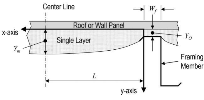
Figure A9.4.6.1 Geometry of single-layer fiberglass batt.
where X = distance from edge of purlin or girt, ft Y = distance from edge of roof panel or wall panel, ft L = length from edge of purlin or girt to centerline of cavity, ft wf = width of purlin or girt flange, ft Yo = distance between purlin or girt and the roof panel or wall panel, ft Ym = distance from edge of roof panel or wall panel at the cavity centerline, ft
d. For calculation purposes, the effective R-value for insulation installed in cavities in steel-framed walls
shall be taken from Table A9.2-2.
A9.4.4 Building Material Thermal Properties. R-values for building materials shall be taken from Table A9.4.4-1. Concrete block R-values shall be calculated using the isothermal planes method or a twodimensional calculation program, thermal conductivities from Table A9.4.2-2, and dimensions from ASTM C90. The parallel path calculation method is not acceptable.
Exception to A9.4.4: R-values for building materials or thermal conductivities determined from testing
in accordance with Section A9.3.
A9.4.5 Building Material Heat Capacities. The HC of assemblies shall be calculated using published values for the unit weight and specific heat of all building material components that make up the assembly.
A9.4.6 Metal Building U-Factor Equations. The calculation procedures in this section shall use a fixed purlin and girt spacing of 60 in., and the results shall be permitted to be used in accordance with Sections A2.3.3 and A3.2.3. For single-layer metal building roof and single-layer compressed metal building wall systems, the calculation procedure outlined in Section A9.4.6.1 shall be used to calculate the assembly U- factor . For double-layer metal building roof systems, the calculation procedure outlined in Section A9.4.6.2 shall be used to calculate the assembly U-factor . For single-layer in cavity and double-layer metal build- ing wall systems, the calculation procedure outlined in Section A9.4.6.3 shall be used to calculate the assembly U-factor . Each of the above insulation methods and calculation procedures also shall be used where continuous insulation is applied to the assembly. The calculation procedures outlined in this section shall not be used for other metal building roof and wall systems.
A9.4.6.1 Single-Layer Roof and Single-Layer Compressed Wall. The U-factor of metal building roofs or metal building walls that are insulated with a single layer of fiberglass insulation (see Figure A9.4.6.1) shall be calculated using the procedure outlined in this section. The procedure assumes the insulation is compressed over the purlin or girt. There may also be a thermal spacer block present.
There are six steps in the calculation process:
 - Step 1—Characterize the thermal conductivity of the fiberglass.

 - Step 2—Determine the _U-factor_ for the insulation in the cavity.

 - Step 3—Determine the _U-factor_ over the structural framing member.

 - Step 4—Area weight the _U-factors_ calculated in Steps 2 and 3.

 - Step 5—Determine the _U-factor_ from the finite element analysis results.

 - Step 6—Determine the _U-factor_ for any _continuous insulation_ if present.
Step 1: The thermal conductivity of the fiberglass batt insulation is represented by a thermal curve of the form in Equation A9.4-2:
266 ANSI/ASHRAE/IES Standard 90.1-2022 (I-P)
PDF Page 269
C k = A + B +
[—] [-]
where k = thermal conductivity, Btu/h·ft·°F = density, lb/ft [3]
A = 0.014917 B = 0.0004377 C = 0.0056897 Step 2: Assume the fiberglass batt forms a parabolic profile defined by Equation A9.4-3:
X
Y = Yo + Ym - Yo [X] [---] L 2 - [---] L
Determine the cavity U-factor ( Uc ) using Equation A9.4-4:
(A9.4-2)
(A9.4-3)
(A9.4-4)
B oto
Uc
oto 2 YoYm
Ym - Yo 1 + ---------------- - --------------------------- Ym 1 - Y ---------------- m - Y - o Y
1 + Y ---------------- m - Y - o
--------------------------- Ym
1 - Y ---------------- m - Y - o
- ---------------- -
--------------------------- Ym
- Y ---------------- m - Y - o Ym
where o = reference density of the fiberglass, lb/ft [3]
to = reference thickness of the fiberglass, ft The properties of fiberglass insulation are presented in Table A9.4.6.1. Include the thermal resistance s of the interior ( Ri ) and exterior ( Re ) air films to calculate the overall cavity U-factor ( Uco ) using Equation A9.4-5:
Uco
1 = -----------------------------1 ---- U - c + Ri + Re
(A9.4-5)
Step 3: Determine the U-factor ( Ufo ) over the structural framing member. The variable Yo represents the total combined thickness of the thermal spacer block and the compressed insulation. The density of the compressed insulation is determined by Equation A9.4-6:
c
= --------- oto tc
where
c = density of the compressed insulation over the framing member, lb/ft [3 ] tc = thickness of the compressed insulation over the framing member, ft Determine the thermal resistance of the compressed insulation ( Rc ) using Equation A9.4-7:
(A9.4-6)
(A9.4-7)
Rc
= ------------------------------------- tc - A + B c + C c
Determine the overall framing U-factor ( Ufo ) at the structural framing member, including the air film resistances, using Equation A9.4-8:
Ufo
1 = -------------------------------------------RTB + Rc + Ri + Re
(A9.4-8)
where Ufo = U-factor over the structural framing member, Btu/h·ft [2] ·°F RTB = R-value of the thermal spacer block, h·ft [2] ·°F/Btu Rc = R-value of the compressed insulation, h·ft [2] ·°F/Btu
ANSI/ASHRAE/IES Standard 90.1-2022 (I-P) 267
PDF Page 270
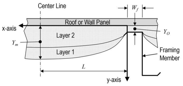
Figure A9.4.6.2-1 Geometry of double layers of fiberglass batts.
where X = distance from edge of purlin or girt, ft Y = distance from edge of roof panel or wall panel, ft L = length from edge of purlin or girt to centerline of cavity, ft wf = width of purlin or girt flange, ft Yo = distance between purlin or girt and the roof panel or wall panel, ft Ym = distance from edge of roof panel or wall panel at the cavity centerline, ft
Step 4: Determine the overall area-weighted U-factor for the entire system using Equation A9.4-9:
Ues
= L ------------------------------------------------------ Uco + wf 2 Ufo - L + wf 2
where
Ues = area-weighted U-factor for the entire system, Btu/h·ft [2] ·°F
wf = width of purlin or girt flange, ft
Step 5: Calculate the adjusted overall U-factor ( Uadj ) using Equation A9.4-10:
(A9.4-9)
(A9.4-10)
Uadj
1 = --------------------------------------------------0.8676 Ues + 1.1423
where
Uadj = adjusted overall U-factor represented by correlation with the finite element modeling, Btu/h·ft [2] ·°F
Step 6: If there is any continuous insulation present, calculate the overall U-factor using Equation A9.4-11:
1 U = ---------------------- - 1 -------- Uadj - + Rci
(A9.4-11)
A9.4.6.2 Double-Layer Roof. The U-factor of metal building roofs that are insulated with double layers of fiberglass insulation (see Figure A9.4.6.2-1) shall be calculated using the procedure outlined in this section. The procedure assumes the insulation is compressed over the purlin and there may be a thermal spacer block present.
There are six steps in the calculation process:
 - Step 1—Characterize the thermal conductivity of the fiberglass.

 - Step 2—Determine the _U-factor_ for the insulation in the cavity.

 - Step 3—Determine the _U-factor_ over the structural framing member.

 - Step 4—Area weight the _U-factors_ calculated in Steps 2 and 3.

 - Step 5—Determine the _U-factor_ from the finite element analysis results.

 - Step 6—Determine the _U-factor_ for any _continuous insulation_ if present.
Step 1: The thermal conductivity of the fiberglass batt insulation is represented by a thermal curve of the form in Equation A9.4-12:
268 ANSI/ASHRAE/IES Standard 90.1-2022 (I-P)
PDF Page 271
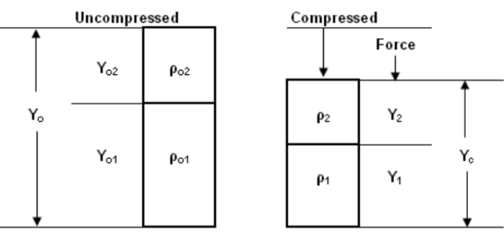
Figure A9.4.6.2-2 Compression of double layers of fiberglass insulation.
C k = A + B +
[—] [-]
where k = thermal conductivity, Btu/h·ft [2] ·°F = density, lb/ft [3]
(A9.4-12)
A = 0.014917 B = 0.0004377 C = 0.0056897 Step 2: Assume the double-layer fiberglass batt forms a parabolic profile defined by Equation A9.4-13:
X
Y = Yo + Ym - Yo [X] [---] L 2 - [---] L
(A9.4-13)
The presence of two layers of fiberglass adds complexity because each layer has distinct reference properties (see Table A9.4.6.1). As the double layers are compressed, the thickness of each layer needs to be determined by considering that each layer achieves the same compressive force. Instead of having a closedform analytical solution that predicts the U-factor for the cavity, the double-layer system requires that the parabolic profile be numerically integrated. The compression of the double-layer system is presented in Figure A9.4.6.2-2.
The thickness of the second layer ( Y 2) is described by Equation A9.4-14:
Y -----2 Yc
---------------------------------------------------- - - 1 o 21 - o 22 Yc 12
o 2 1
2 - o 2
1 2
Y -----2 - o 2 W 2 Yc o 21 - o 22
2 - o 2
1 2
(A9.4-14)
(A9.4-15a)
(A9.4-15b)
where Yc = compressed thickness of the double layers, ft o 1 = reference density of first layer, lb/ft [3]
o 2 = reference density of second layer, lb/ft [3]
W 1 = reference weight of first layer, lb/ft [2]
W 2 = reference weight of second layer, lb/ft [2]
The solutions to Equation A9.4-14 are Equations A9.4-15a and A9.4-15b:
where a = 1
ANSI/ASHRAE/IES Standard 90.1-2022 (I-P) 269
PDF Page 272
b =
c =
---------------------------------------------------- - - 1 o 21 - o 22 Yc 12
----------------------------------------------- - o 21 - o 22 Yc 12
o 2 W 2 o 2 - o 2 1 2
o 1 W 1 + o 2 W 2
2 - o 2
1 2
o 2 1
2 - o 2
1 2
Select the smaller value of Y 2, a and Y 2, b as Y 2. Y 1 shall be calculated as the difference between Yc and Y 2. Next, the R-values for the two compressed layers of insulation shall be calculated and converted to a U-factor . This process shall be repeated along the entire profile and the results numerically integrated using maximum 0.04167 ft increments. It is important to note that Equation A9.4-14 does not apply when the two layers of insulation are the same material. In this case, each compressed layer has the same thickness, which simplifies the U-factor calculations. The numerical integration still needs to be completed to determine the Uco .
Step 3: Determine the U-factor over the structural framing member. The variable Yo represents the thickness of the thermal spacer block and the thickness of the compressed insulation. The density of the compressed insulation is determined by Equation A9.4-16:
c
= --------- oto tc
where
c = density of the compressed insulation over the framing member, lb/ft [3]
tc = thickness of the compressed insulation over the framing member, ft The thermal resistance of the compressed insulation is determined by Equation A9.4-17:
(A9.4-16)
(A9.4-17)
Rc
= ------------------------------------- tc - A + B c + C c
Determine the overall framing U-factor ( Ufo ) at the structural framing member, including the air film resistances, using Equation A9.4-18:
Ufo
1 = ------------------------------------------- - RTB + Rc + Ri + Re
(A9.4-18)
where Ufo = U-factor over the structural framing member, Btu/h·ft [2] ·°F RTB = R-value of the thermal spacer block, h·ft [2] ·°F/Btu Rc = R-value of the compressed insulation, h·ft [2] ·°F/Btu Step 4: Determine the overall area-weighted U-factor for the entire system using Equation A9.4-19:
Ues
= L -------------------------------------------------------- Uco + wf 2 Ufo L + wf 2
where Ues = area-weighted U-factor for the entire system, Btu/h·ft [2] ·°F
Step 5: Calculate the adjusted overall U-factor ( Uadj ) using Equation A9.4-20:
(A9.4-19)
(A9.4-20)
Uadj
1 = --------------------------------------------------0.8676 Ues + 1.1423
where Uadj = adjusted overall U-factor represented by correlation with the finite element modeling, Btu/h·ft [2] ·°F Step 6: If there is any continuous insulation present, calculate the overall U-factor using Equation A9.4-21:
Uo
1 = ---------------------- - 1 -------- Uadj - + Rci
(A9.4-21)
A9.4.6.3 Single-Layer in Cavity and Double-Layer Walls. The U-factor of metal building walls that are insulated with a single-layer in cavity or multiple layers of mineral fiber insulation (see Figure A9.4.6.3) shall be calculated using the procedure outlined in this section. For double-layer walls, the procedure assumes that the outer layer of insulation is compressed between the wall panel and girt. There may also be
270 ANSI/ASHRAE/IES Standard 90.1-2022 (I-P)
PDF Page 273
a thermal spacer block or continuous insulation present. Air spaces may also exist depending on the specific drape profiles.
There are nine steps in the calculation process:
-
Step 1—Characterize the thermal conductivity of the mineral fiber insulation.
-
Step 2—Define the parabolic profiles for each insulation layer.
-
Step 3—Calculate the R-values for insulation and air spaces in cavity both outside and inside insulation layers, including air films.
-
Step 4—Calculate the R-value inside the girt and adjacent to the web.
-
Step 5—Calculate the R-value outside the girt.
-
Step 6—Add the R-values inside and outside the girt, including air films.
-
Step 7—Calculate the overall insulation assembly using the R-values in Steps 3 and 6.
-
Step 8—Calculate the U-factor from the finite element analysis results.
-
Step 9—Calculate the U-factor for any continuous insulation if present.
Step 1: The thermal conductivity of the mineral fiber insulation is represented by a thermal curve of the form in Equation A9.4-22:
(A9.4-22)
= A + B --------- o - o + C --------- y - y o o
k = A + B
o o
where k = thermal conductivity, Btu·ft/h·ft [2] ·°F - = nominal density, lb/ft [3]
- = nominal thickness, ft y = thickness of insulation, ft A = 0.014917 B = 0.0004377 C = 0.0056897 Step 2: Assume that each layer of mineral fiber has a parabolic profile defined by Equation A9.4-23:
---------------- y - Yo - = ----- x 2 - ----- x Ym - Yo xm xm
(A9.4-23)
where x = distance from edge of girt, ft y = distance from edge of wall panel, ft Yo = insulation thickness at x = 0, ft Ym = insulation thickness at x = Xm, ft Step 3: Calculate R-values for the insulation and air spaces in the cavity both inside and outside insulation layers, including air films.
Because the configuration can possibly consist of both mineral fiber insulation and an air space, the composite is given by Equation A9.4-24:
R = ---- x 1 a x 0 a k ---- ya + Y ------------- mk – y
xa ---- y + Y ------------- m - y - dx + ------------ Ym -
0 ka k k Ym
1 xa
= ----
---- y + ------------- m - dx k k
(A9.4-24)
where ka is the thermal conductivity of air in Btu·ft/h·ft [2] ·°F.
The trapezoidal integration method is used to evaluate the integral and calculate R and is given by Equation A9.4-25:
b
f x dx
a
12 [-] [-] Nk = 1 xk + 1 – xk yk + yk + 1
(A9.4-25)
where xk = point to analyze along the x -axis, ft xk +1 = point ahead of the point being analyzed, ft yk = thickness at point being analyzed, ft yk +1 = thickness at point ahead of the point being analyzed, ft
ANSI/ASHRAE/IES Standard 90.1-2022 (I-P) 271
PDF Page 274
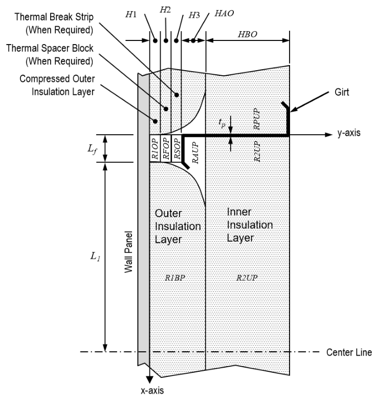
Figure A9.4.6.3 Geometry of single cavity layer or double-layer wall.
The integral represents the combined R-value of the air space and insulation over the region 0 < x < Xa . Because the thermal conductivity of air is independent of the thickness, Equation A9.4-25 can be simplified using the air space mean thickness ( Ya ) to produce Equation A9.4-26:
------------- m - dx K
R
= ---- Ya - + -----1 xa
---- KYa - a + ----- X 1 a x 0 a Y ------------- mK – y
xa Y ------------- m - y - dx + --------------- Ym
0 K K Ym
(A9.4-26)
However, if the air space is characterized by convection instead of conduction then the term Ya / ka can be replaced by the R-value for convection (R-0.92 h·ft [2] ·°F/Btu for walls ). Adding the inside and outside layers is expressed in Equation A9.4-27:
RBP = R 1 BP + R 2 BP
(A9.4-27)
Add the air film resistances at the exterior ( RAT ) and interior ( RAB ), which are defined as Equation A9.4-28:
RAB
1 = -------hAB
where hAB is the air film heat transfer coefficient at the exterior in Btu/h·ft [2] ·°F.
(A9.4-28)
(A9.4-29)
RAT
1 = ------ - hAT
where hAT is the air film heat transfer coefficient at the interior in Btu/h·ft [2] ·°F.
The sum of the R-values for the insulation and air films beyond the girt are expressed in Equation A9.4-30.
RBP + air = RBP + RAB + RAT
(A9.4-30)
272 ANSI/ASHRAE/IES Standard 90.1-2022 (I-P)
PDF Page 275
Step 4: Calculate the R-values inside the girt and adjacent to the web. The R-values inside the girt are the air space (RAUP) added in series with the insulation (R2UP); their combined value is then added in parallel to RPUP. Depending on the thickness of the air space, it can be modeled as conduction as shown in Equation A9.4-31:
H 3 RAUP = ------ ka
(A9.4-31)
where H 3 = thickness of the air space, ft ka = thermal conductivity of air, Btu·ft/h·ft [2] ·°F When appropriate, the air space can be modeled as convection, which is a constant R-0.92 h·ft [2] ·°F/Btu for walls .
The R-value for R2UP is expressed in Equation A9.4-32. The insulation thickness is also not limited by the girt height and can extend beyond it.
H 4 R2UP =
= ----------------------------------------------
(A9.4-32)
- B --------- - + C --------- -
H 4 o o
A + B
o o
--------- o - o + C --------- [H] [4] H 4
where H 4 is the thickness of the mineral fiber at x = 0 in feet.
The R-value of the web (RPUP) is calculated using 26.2 h·ft [2] ·°F/Btu as the thermal conductivity of the girt in Equation A9.4-33:
Web Height RPUP = --------------------------- -
kp
(A9.4-33)
where kp = thermal conductivity of the girt, Btu·ft/h·ft [2] ·°F Web Height = height of the girt, ft The addition of the air space and insulation in series are combined to be in parallel with the girt, which is expressed as Equation A9.4-34:
----------- Lf = ----------------------------------- Lf - tp - + ------------- tp - RUP RAUP + R2UP RPUP
Equation A9.4-34 can be rearranged and solved for RUP as presented in Equation A9.4-35:
RAUP + R2UP RPUP RUP = --------------------------------------------------------------------------------------- Lf - tp RPUP + tp RAUP + R2UP Lf
(A9.4-34)
(A9.4-35)
Because the thickness of the girt is significantly less than the flange width ( Lf ), Equation A9.4-35 can be simplified as Equation A9.4-36. However it is important to note that RUP will be close to 2 or lower (depending on how the air is modeled) because of the significant effects of the steel girt:
RAUP + R2UP RPUP RUP = ------------------------------------------------------------------------ Lf RPUP + tp RAUP + R2UP Lf
(A9.4-36)
Step 5: Calculate the R-value outside the girt. Typical construction above the girt consists of a thermal spacer block and compressed mineral fiber insulation. These two insulations are in series, and the total R-value ( ROPI ) is expressed as Equation A9.4-37. If there is thermal break tape present it is included as the third insulation in this series.
(A9.4-37)
ROPI
= ------- + ------ kf kI
H 1
H 1 H 2
------- + ------kf kI
where H 1 = thickness of thermal spacer block, ft H 2 = thickness of compressed mineral fiber insulation, ft kf = thermal conductivity of the thermal spacer block, Btu·ft/h·ft [2] ·°F kI = thermal conductivity of the compressed mineral fiber insulation, Btu·ft/h·ft [2] ·°F
ANSI/ASHRAE/IES Standard 90.1-2022 (I-P) 273
PDF Page 276
The impact of the thermal bridging associated with the outside of the girt and the insulation is to reduce the thermal resistance of the insulation. The reduction is calculated using Equation A9.4-38:
(A9.4-38)
1 + ---------------------------- Lf
ROP = ROPI
1
Step 6 : Add the R-values inside and outside the girt including air films. The total thermal resistance associated with the girt is the sum of the R-values inside and outside the girt as shown in Equation A9.4-39:
RTP = RUP + ROP
(A9.4-39)
The next calculation is to add the inside and outdoor air film coefficients using Equation A9.4-40:
RTP + air = RTP + RAB + RAT
Step 7: Calculate the overall insulation assembly using the R-values in Steps 3 and 6. The overall insulation system R-value is determined using Equation A9.4-41:
Rinsul - sys
= -------------------------------------------------------------- 2 L 1 + Lf RBP + airRTP + air - 2 L 1 RTP + air + LfRBP + air
Step 8: Calculate the U-factor from the finite element analysis results. The overall U-factor for the insulation assembly is determined using Equation A9.4-42:
(A9.4-40)
(A9.4-41)
(A9.4-42)
Uadj
1 = ---------------------------------------------------------- - 0.8627 Rinsul - sys + 1.132
where Uadj = adjusted overall U-factor represented by the correlation with the finite element modeling in Btu/ h·ft [2] ·°F. Step 9: Calculate the overall U-factor for any continuous insulation if present. If there is any continuous insulation present, first calculate the R-value adjacent to the flange using Equation A9.4-43:
= R ----------------------------
RBFci = Rci
1 + 2-------------- hci
1
(A9.4-43)
- ------------- Lf
where RBFci = thermal resistance of continuous insulation adjacent to the flange, h·ft [2] ·°F/Btu Rci = thermal resistance of the continuous insulation, h·ft [2] ·°F/Btu hci = thickness of the continuous insulation, ft Next, calculate the area-weighted R-value for the continuous insulation using Equation A9.4-44:
Roci
= ---------------------------------------------2 L 1 + Lf RBPciRci 2 L 1 RBPci + LfRci
where Roci = overall thermal resistance of continuous insulation in h·ft [2] ·°F/Btu Finally, calculate the overall U-factor using Equation A9.4-45:
(A9.4-44)
(A9.4-45)
Uo
1 = -------------------------1 -------- Uadj - + Roci
A9.4.7 Insulated Metal Panels. U-factors of insulated metal panels shall be determined by two- or threedimensional finite difference or finite volume computer models or by testing in accordance with Section A9.3.2 and shall include panel side joints.
A10. THERMAL BRIDGING CHI FACTORS AND PSI FACTORS
A10.1 Determination of Psi-Factors and Chi-Factors. Psi-factor (ψ) and chi-factor (χ) values representative of an as-designed thermal bridging condition shall be determined in accordance with one of the following:
274 ANSI/ASHRAE/IES Standard 90.1-2022 (I-P)
PDF Page 277
a. From simulation models compliant with ISO 10211 using details representative of the actual construc tion and modeling assumptions consistent with generally accepted architectural and engineering practice. b. From ISO 14683. c. From testing of the assembly in accordance with ASTM C1363 with and without the presence of the
thermal bridge condition to determine a linear transmittance value or point transmittance value for the thermal bridge condition. d. From application of heat transfer theory in accordance with generally accepted engineering practice and
where approved by the a uthority having jurisdiction . e. As indicated in Table A10.1. The default column shall be used where the thermal bridge meets prescrip tive requirements. The unmitigated column shall be used where the thermal bridge does not meet the prescriptive requirements.
( Informative Note: In Table A10.1, the values for thermal bridge details prescribed in Section 5.5.5 are based on data from ASHRAE Research Project 1365 and the BC Hydro Thermal Bridging Guide listed in Informative Appendix E.)
A10.2 Assembly U-Factor Adjustment for Simulation of Thermal Bridges. For the purpose of incorporating the effects of thermal bridges in simulations as required by Section 12 and Normative Appendix G, where a thermal bridge is not modeled as a separate element, the clear-field U-factors of modeled assemblies shall be modified in accordance with Equation A10.2. This modification shall be achieved in the simulation model by altering the conductance value assigned to any one or more insulation layers within the modeled assembly without altering the properties of modeled building material layers.
Utot = {[(∑ψ i × Li ) + (∑χ j × nj )]/ Atotal ) + Uo } (A10.2)
where Utot = overall thermal transmittance, including the effect of linear thermal bridges and point thermal bridges not included in the construction assembly Uo -factor, Btu/(h·ft [2] ·°F) Uo = clear-field thermal transmittance of the construction assembly as determined in accordance with Section 5, Btu/(h·ft [2] ·°F) Atotal = total opaque projected surface area of the construction assembly, ft [2]
ψ i = psi-factor, thermal transmittance for each type of linear thermal bridge, Btu/(h·ft [2] ·°F) Li = length of a particular linear thermal bridge as measured on the outside surface of the building envelope, ft [2]
χ i = chi-factor, thermal transmittance for each detail type of point thermal bridge, Btu/(h·°F) ni = number of occurrences a particular type of point thermal bridge
ANSI/ASHRAE/IES Standard 90.1-2022 (I-P) 275
PDF Page 278
Table A9.2-1 Effective Insulation/Framing Layer R-Values for Roof and Floor Insulation Installed between Metal Framing (4 ft on Center)
| Rated R-Value of Insulation | Correction Factor | Framing/Cavity R-Value |
|---|---|---|
| 0.00 | 1.00 | 0.00 |
| 4.00 | 0.97 | 3.88 |
| 5.00 | 0.96 | 4.80 |
| 8.00 | 0.94 | 7.52 |
| 10.00 | 0.92 | 9.20 |
| 11.00 | 0.91 | 10.01 |
| 12.00 | 0.90 | 10.80 |
| 13.00 | 0.90 | 11.70 |
| 15.00 | 0.88 | 13.20 |
| 16.00 | 0.87 | 13.92 |
| 19.00 | 0.86 | 16.34 |
| Rated R-Value of Insulation | Correction Factor | Framing/Cavity R-Value |
|---|---|---|
| 20.00 | 0.85 | 17.00 |
| 21.00 | 0.84 | 17.64 |
| 24.00 | 0.82 | 19.68 |
| 25.00 | 0.81 | 20.25 |
| 30.00 | 0.79 | 23.70 |
| 35.00 | 0.76 | 26.60 |
| 38.00 | 0.74 | 28.12 |
| 40.00 | 0.73 | 29.20 |
| 45.00 | 0.71 | 31.95 |
| 50.00 | 0.69 | 34.50 |
| 55.00 | 0.67 | 36.85 |
Table A9.2-2 Effective Insulation/Framing Layer R-Values for Wall Insulation Installed Between Steel Framing
Empty Cavity, No Insulation
4 3.5 R-0.91 0.79 0.91
Insulated Cavity
| 4 | 3.5 | R-11 | 5.5 | 6.6 |
|---|---|---|---|---|
| 4 | 3.5 | R-13 | 6.0 | 7.2 |
| 4 | 3.5 | R-15 | 6.4 | 7.8 |
| 6 | 6.0 | R-19 | 7.1 | 8.6 |
| 6 | 6.0 | R-21 | 7.4 | 9.0 |
| 8 | 8.0 | R-25 | 7.8 | 9.6 |
Table A9.4.2-1 R-Values for Cavity Air Spaces [ a]
| Component | Air Space Thickness, in. | Climate Zone 1 Effective Emittance | Col4 | Col5 | Col6 | Climate Zone 2 Effective Emittance | Col8 | Col9 | Col10 | Climate Zone 3 Effective Emittance | Col12 | Col13 | Col14 |
|---|---|---|---|---|---|---|---|---|---|---|---|---|---|
| Component | Air Space Thickness, in. | 0.05 | 0.20 | 0.50 | 0.82 | 0.05 | 0.20 | 0.50 | 0.82 | 0.05 | 0.20 | 0.50 | 0.82 |
| Roof | 0.50 | 2.5 | 1.9 | 1.2 | 0.9 | 2.4 | 1.8 | 1.2 | 0.9 | 2.2 | 1.7 | 1.1 | 0.9 |
| Roof | 0.75 | 3.5 | 2.4 | 1.4 | 1.0 | 3.2 | 2.2 | 1.4 | 1.0 | 2.8 | 2.0 | 1.3 | 0.9 |
| Roof | 1.50 | 5.6 | 3.1 | 1.7 | 1.1 | 4.9 | 2.9 | 1.6 | 1.1 | 4.2 | 2.5 | 1.5 | 1.0 |
| Roof | 3.50 | 8.0 | 3.8 | 1.9 | 1.2 | 7.0 | 3.4 | 1.7 | 1.1 | 5.9 | 3.0 | 1.6 | 1.1 |
| Wall | 0.50 | 2.5 | 1.8 | 1.2 | 0.9 | 2.5 | 1.8 | 1.2 | 0.9 | 2.5 | 1.8 | 1.2 | 0.9 |
| Wall | 0.75 | 2.8 | 2.0 | 1.3 | 0.9 | 2.8 | 2.0 | 1.3 | 0.9 | 2.8 | 2.0 | 1.3 | 0.9 |
| Wall | 1.50 | 2.5 | 1.8 | 1.2 | 0.9 | 2.5 | 1.8 | 1.2 | 0.9 | 2.5 | 1.8 | 1.2 | 0.9 |
| Wall | 3.50 | 2.6 | 1.9 | 1.3 | 0.9 | 2.6 | 1.9 | 1.3 | 0.9 | 2.6 | 1.9 | 1.3 | 0.9 |
a. Interpolation shall be permitted to be used for effective emittance values and air space thicknesses between those listed. Extrapolation below an effective emittance of 0.05 is not
permitted.
276 ANSI/ASHRAE/IES Standard 90.1-2022 (I-P)
PDF Page 279
Table A9.4.2-1 R-Values for Cavity Air Spaces [ a] (Continued)
| Component Floor Component | Air Space Thickness, in. | Climate Zone 1 Effective Emittance | Col4 | Col5 | Col6 | Climate Zone 2 Effective Emittance | Col8 | Col9 | Col10 | Climate Zone 3 Effective Emittance | Col12 | Col13 | Col14 |
|---|---|---|---|---|---|---|---|---|---|---|---|---|---|
| Floor Component Component | Air Space Thickness, in. | 0.05 | 0.20 | 0.50 | 0.82 | 0.05 | 0.20 | 0.50 | 0.82 | 0.05 | 0.20 | 0.50 | 0.82 |
| Floor Component Component | 0.50 | 1.6 | 1.3 | 1.0 | 0.8 | 1.8 | 1.4 | 1.0 | 0.8 | 1.9 | 1.5 | 1.1 | 0.8 |
| Floor Component Component | 0.75 | 1.7 | 1.4 | 1.0 | 0.8 | 2.0 | 1.5 | 1.1 | 0.8 | 2.4 | 1.7 | 1.2 | 0.9 |
| Floor Component Component | 1.50 | 1.9 | 1.5 | 1.1 | 0.8 | 2.5 | 1.8 | 1.2 | 0.9 | 3.2 | 2.1 | 1.3 | 0.9 |
| Floor Component Component | 3.50 | 2.1 | 1.6 | 1.1 | 0.8 | 3.2 | 2.0 | 1.2 | 0.9 | 4.3 | 2.4 | 1.4 | 1.0 |
| Floor Component Component | Air Space Thickness, in. average? | Climate Zone 4 Effective Emittance | Climate Zone 4 Effective Emittance | Climate Zone 4 Effective Emittance | Climate Zone 4 Effective Emittance | Climate Zone 5 Effective Emittance | Climate Zone 5 Effective Emittance | Climate Zone 5 Effective Emittance | Climate Zone 5 Effective Emittance | Climate Zone 6 Effective Emittance | Climate Zone 6 Effective Emittance | Climate Zone 6 Effective Emittance | Climate Zone 6 Effective Emittance |
| Floor Component Component | Air Space Thickness, in. average? | 0.05 | 0.20 | 0.50 | 0.82 | 0.05 | 0.20 | 0.50 | 0.82 | 0.05 | 0.20 | 0.50 | 0.82 |
| 2 facing layers e ittence | average? | average? | average? | average? | average? | average? | average? | average? | average? | average? | average? | average? | average? |
| Roof Wall Floor Component Roof Wall Floor | Roof Wall Floor Component Roof Wall Floor | Roof Wall Floor Component Roof Wall Floor | Roof Wall Floor Component Roof Wall Floor | Roof Wall Floor Component Roof Wall Floor | Roof Wall Floor Component Roof Wall Floor | Roof Wall Floor Component Roof Wall Floor | Roof Wall Floor Component Roof Wall Floor | Roof Wall Floor Component Roof Wall Floor | Roof Wall Floor Component Roof Wall Floor | Roof Wall Floor Component Roof Wall Floor | Roof Wall Floor Component Roof Wall Floor | Roof Wall Floor Component Roof Wall Floor | Roof Wall Floor Component Roof Wall Floor |
| Roof Wall Floor Component Roof Wall Floor | 0.50 | 2.0 | 1.6 | 1.1 | 0.8 | 1.9 | 1.5 | 1.1 | 0.8 | 1.8 | 1.4 | 1.0 | 0.8 |
| Roof Wall Floor Component Roof Wall Floor | 0.75 | 2.5 | 1.8 | 1.2 | 0.9 | 2.3 | 1.7 | 1.1 | 0.9 | 2.1 | 1.6 | 1.1 | 0.8 |
| Roof Wall Floor Component Roof Wall Floor | 1.50 | 3.5 | 2.2 | 1.3 | 0.9 | 3.1 | 2.0 | 1.3 | 0.9 | 2.8 | 1.9 | 1.2 | 0.9 |
| Roof Wall Floor Component Roof Wall Floor | 3.50 | 4.7 | 2.6 | 1.4 | 1.0 | 4.1 | 2.4 | 1.4 | 1.0 | 3.6 | 2.2 | 1.3 | 0.9 |
| Roof Wall Floor Component Roof Wall Floor | 0.50 | 2.5 | 1.8 | 1.2 | 0.9 | 2.5 | 1.8 | 1.2 | 0.9 | 2.5 | 1.8 | 1.2 | 0.9 |
| Roof Wall Floor Component Roof Wall Floor | 0.75 | 2.8 | 2.0 | 1.3 | 0.9 | 2.8 | 2.0 | 1.3 | 0.9 | 2.8 | 2.0 | 1.3 | 0.9 |
| Roof Wall Floor Component Roof Wall Floor | 1.50 | 2.5 | 1.8 | 1.2 | 0.9 | 2.5 | 1.8 | 1.2 | 0.9 | 2.5 | 1.8 | 1.2 | 0.9 |
| Roof Wall Floor Component Roof Wall Floor | 3.50 | 2.6 | 1.9 | 1.3 | 0.9 | 2.6 | 1.9 | 1.3 | 0.9 | 2.6 | 1.9 | 1.3 | 0.9 |
| Roof Wall Floor Component Roof Wall Floor | 0.50 | 2.1 | 1.6 | 1.1 | 0.8 | 2.2 | 1.7 | 1.1 | 0.9 | 2.3 | 1.7 | 1.2 | 0.9 |
| Roof Wall Floor Component Roof Wall Floor | 0.75 | 2.7 | 1.9 | 1.2 | 0.9 | 2.9 | 2.0 | 1.3 | 0.9 | 3.1 | 2.1 | 1.3 | 1.0 |
| Roof Wall Floor Component Roof Wall Floor | 1.50 | 3.9 | 2.4 | 1.4 | 1.0 | 4.3 | 2.6 | 1.5 | 1.0 | 4.7 | 2.7 | 1.5 | 1.1 |
| Roof Wall Floor Component Roof Wall Floor | 3.50 | 5.5 | 2.9 | 1.5 | 1.1 | 6.0 | 3.1 | 1.6 | 1.1 | 6.6 | 3.3 | 1.7 | 1.1 |
| Roof Wall Floor Component Roof Wall Floor | Air Space Thickness, in. | Climate Zone 7 Effective Emittance | Climate Zone 7 Effective Emittance | Climate Zone 7 Effective Emittance | Climate Zone 7 Effective Emittance | Climate Zone 8 Effective Emittance | Climate Zone 8 Effective Emittance | Climate Zone 8 Effective Emittance | Climate Zone 8 Effective Emittance | ||||
| Roof Wall Floor Component Roof Wall Floor | Air Space Thickness, in. | 0.05 | 0.20 | 0.50 | 0.82 | 0.05 | 0.20 | 0.50 | 0.82 | 0.82 | 0.82 | 0.82 | 0.82 |
| Roof Wall Floor Component Roof Wall Floor | 0.50 | 1.8 | 1.4 | 1.0 | 0.8 | 1.6 | 1.3 | 1.0 | 0.8 | 0.8 | 0.8 | 0.8 | 0.8 |
| Roof Wall Floor Component Roof Wall Floor | 0.75 | 2.0 | 1.6 | 1.1 | 0.8 | 1.8 | 1.4 | 1.0 | 0.8 | 0.8 | 0.8 | 0.8 | 0.8 |
| Roof Wall Floor Component Roof Wall Floor | 1.50 | 2.6 | 1.8 | 1.2 | 0.9 | 2.1 | 1.6 | 1.1 | 0.8 | 0.8 | 0.8 | 0.8 | 0.8 |
| Roof Wall Floor Component Roof Wall Floor | 3.50 0.50 | 3.2 2.5 | 2.0 1.8 | 1.3 1.2 | 0.9 0.9 | 2.4 2.5 | 1.7 1.8 | 1.2 1.2 | 0.9 0.9 | 0.9 0.9 | 0.9 0.9 | 0.9 0.9 | 0.9 0.9 |
| Roof Wall Floor Component Roof Wall Floor | 0.75 | 2.8 | 2.0 | 1.3 | 0.9 | 2.8 | 2.0 | 1.3 | 0.9 | 0.9 | 0.9 | 0.9 | 0.9 |
| Roof Wall Floor Component Roof Wall Floor | 1.50 | 2.5 | 1.8 | 1.2 | 0.9 | 2.5 | 1.8 | 1.2 | 0.9 | 0.9 | 0.9 | 0.9 | 0.9 |
| Roof Wall Floor Component Roof Wall Floor | 3.50 | 2.6 | 1.9 | 1.3 | 0.9 | 2.6 | 1.9 | 1.3 | 0.9 | 0.9 | 0.9 | 0.9 | 0.9 |
| Roof Wall Floor Component Roof Wall Floor | 0.50 | 2.3 | 1.8 | 1.2 | 0.9 | 2.5 | 1.8 | 1.2 | 0.9 | 0.9 | 0.9 | 0.9 | 0.9 |
| Roof Wall Floor Component Roof Wall Floor | 0.75 | 3.2 | 2.2 | 1.4 | 1.0 | 3.4 | 2.3 | 1.4 | 1.0 | 1.0 | 1.0 | 1.0 | 1.0 |
| Roof Wall Floor Component Roof Wall Floor | 1.50 | 4.9 | 2.8 | 1.6 | 1.1 | 5.4 | 3.1 | 1.7 | 1.1 | 1.1 | 1.1 | 1.1 | 1.1 |
| Roof Wall Floor Component Roof Wall Floor | 3.50 | 6.9 | 3.4 | 1.7 | 1.1 | 7.7 | 3.7 | 1.8 | 1.2 | 1.2 | 1.2 | 1.2 | 1.2 |
a. Interpolation shall be permitted to be used for effective emittance values and air space thicknesses between those listed. Extrapolation below an effective emittance of 0.05 is not
permitted.
ANSI/ASHRAE/IES Standard 90.1-2022 (I-P) 277
PDF Page 280
Table A9.4.2-2 Emittance Values of Various Surfaces and Effective Emittances of Air Spaces
| Surface | Average Emissivity e | Effective Emissivity of Air Space | Col4 |
|---|---|---|---|
| Surface | Average Emissivity****e | One Surface****e; Other, 0.9 | Both Surfaces Emissivity****e |
| Aluminum foil, bright | 0.05 | 0.05 | 0.03a |
| Metalized film, testedb | 0.05 | 0.05 | 0.03a |
| Aluminum sheet | 0.12 | 0.12 | 0.06 |
| Aluminum coated paper, polished | 0.20 | 0.20 | 0.11 |
| Steel, galv., bright | 0.25 | 0.24 | 0.14 |
| Aluminum paint | 0.50 | 0.47 | 0.32 |
| Building materials: wood, paper, masonry, nonmetallic paints | 0.90 | 0.82 | 0.82 |
| Regular glass | 0.84 | 0.77 | 0.72 |
| a. When referencing Table A9.4.2-1, use an effective_emittance_ of 0.05. b. Tested_emittance_ in accordance with ASTM C1224 at 0.05 or less. | a. When referencing Table A9.4.2-1, use an effective_emittance_ of 0.05. b. Tested_emittance_ in accordance with ASTM C1224 at 0.05 or less. | a. When referencing Table A9.4.2-1, use an effective_emittance_ of 0.05. b. Tested_emittance_ in accordance with ASTM C1224 at 0.05 or less. | a. When referencing Table A9.4.2-1, use an effective_emittance_ of 0.05. b. Tested_emittance_ in accordance with ASTM C1224 at 0.05 or less. |
Table A9.4.3 Effective R-Values for Fiberglass
Insulation R-Value at Standard Thickness
| Rated R-Value | Col2 | 38 | 30 | 22 | 21 | 19 | 15 | 13 | 11 |
|---|---|---|---|---|---|---|---|---|---|
| Standard Thickness, in. | Standard Thickness, in. | 12 | 9.5 | 6.5 | 5.5 | 6 | 3.5 | 3.5 | 3.5 |
| Nominal Lumber Size, in. | Actual Depth of Cavity, in. | Effective Insulation R-Values when Installed in a Confined Cavity | Effective Insulation R-Values when Installed in a Confined Cavity | Effective Insulation R-Values when Installed in a Confined Cavity | Effective Insulation R-Values when Installed in a Confined Cavity | Effective Insulation R-Values when Installed in a Confined Cavity | Effective Insulation R-Values when Installed in a Confined Cavity | Effective Insulation R-Values when Installed in a Confined Cavity | Effective Insulation R-Values when Installed in a Confined Cavity |
| 2 12 | 11.25 | 37 | |||||||
| 2 10 | 9.25 | 32 | 30 | ||||||
| 2 8 | 7.25 | 27 | 26 | 22 | 21 | 19 | |||
| 2 6 | 5.5 | 21 | 20 | 21 | 18 | ||||
| 2 4 | 3.5 | 14 | 13 | 15 | 13 | 11 | |||
| 2 4 | 2.5 | 9.8 | |||||||
| 2 4 | 1.5 | 6.3 | 6 |
278 ANSI/ASHRAE/IES Standard 90.1-2022 (I-P)
PDF Page 281
| Table A9.4.4-1 R-Values for Building Materials | Col2 | Col3 |
|---|---|---|
| Material | Actual Size, in. | R-Value |
| Carpet and Rubber Pad | 1.23 | |
| Concrete at R-0.0625/in. | 2 | 0.13 |
| Concrete at R-0.0625/in. | 4 | 0.25 |
| Concrete at R-0.0625/in. | 6 | 0.38 |
| Concrete at R-0.0625/in. | 8 | 0.5 |
| Concrete at R-0.0625/in. | 10 | 0.63 |
| Concrete at R-0.0625/in. | 12 | 0.75 |
| Gypsum board | 0.5 | 0.45 |
| Gypsum board | 0.625 | 0.56 |
| Metal Deck | 0 | |
| Roofing, built-up | 0.375 | 0.33 |
| Soil at R-0.104/in. | 12 | 1.25 |
| Steel, Mild | 1 | 0.0031807 |
| Stucco | 0.75 | 0.08 |
| Wood panels, 7/16 in. | 0.438 | 0.62 |
| Wood subfloor | 0.75 | 0.94 |
| Wood, 2 4 at R-1.25/in. | 3.5 | 4.38 |
| Wood, 2 6 at R-1.25/in. | 5.5 | 6.88 |
| Wood, 2 8 at R-1.25/in. | 7.25 | 9.06 |
| Wood, 2 10 at R-1.25/in. | 9.25 | 11.56 |
| Wood, 2 12 at R-1.25/in. | 11.25 | 14.06 |
| Wood, 2 14 at R-1.25/in. | 13.25 | 16.56 |
Table A9.4.4-2 Thermal Conductivity of Concrete Block Material
| Concrete Block Density, lb/ft3 | Thermal Conductivity, Btu·in/h·ft2·°F |
|---|---|
| 80 | 3.7 |
| 85 | 4.2 |
| 90 | 4.7 |
| 95 | 5.1 |
| 100 | 5.5 |
| 105 | 6.1 |
| 110 | 6.7 |
| 115 | 7.2 |
| 120 | 7.8 |
| 125 | 8.9 |
| 130 | 10.0 |
| 135 | 11.8 |
| 140 | 13.5 |
ANSI/ASHRAE/IES Standard 90.1-2022 (I-P) 279
PDF Page 282
Table A9.4.6.1 Fiberglass Reference Properties
| R-Value, h·ft2·°F/Btu | Weight, lb/ft2 | Density, lb/ft3 | Thickness, ft |
|---|---|---|---|
| 10 | 0.149 | 0.605 | 0.2458 |
| 11 | 0.168 | 0.630 | 0.2667 |
| 13 | 0.199 | 0.628 | 0.3167 |
| 16 | 0.243 | 0.634 | 0.3833 |
| 19 | 0.297 | 0.653 | 0.4542 |
| 25 | 0.427 | 0.742 | 0.5750 |
| 30 | 0.520 | 0.766 | 0.6792 |
Table A10.1 Thermal Bridging Psi-Factors and Chi-Factors for Thermal Bridges
| Col1 | Col2 | Col3 | Unmitigated | Col5 | Default | Col7 |
|---|---|---|---|---|---|---|
| Class of Construction— Wall, above Grade | Thermal Bridge Type | Section | Psi-Factor, Btu/(h·ft·°F) | Chi-Factor, Btu/(h·°F) | Psi-Factor, Btu/(h·ft·°F) | Chi-Factor, Btu/(h·°F) |
| _Steel framed_and metal buildings | Roof edge | 5.5.5.1.1 | 0.450 | N/A | 0.140 | N/A |
| _Steel framed_and metal buildings | Parapet | 5.5.5.1.2 | 0.289 | 0.151 | 0.151 | |
| _Steel framed_and metal buildings | Intermediate floor to_wall_ intersection | 5.5.5.2.1 | 0.487 | 0.177 | 0.177 | |
| _Steel framed_and metal buildings | Intermediate floor balcony or overhang to opaque wall intersection | 5.5.5.2.2 | 0.487 | 0.177 | 0.177 | |
| _Steel framed_and metal buildings | Intermediate floor balcony in contact with vertical fenestration | 5.5.5.2.2 | 0.974 | 0.177 | 0.177 | |
| _Steel framed_and metal buildings | Cladding support | 5.5.5.3 | 0.314 | 0.217 | 0.217 | |
| _Steel framed_and metal buildings | Wall to_vertical fenestration_ intersection | 5.5.5.4 | 0.262 | 0.112 | 0.112 | |
| _Steel framed_and metal buildings | Other element and assembly intersections | 5.5.5.5 | N/A | 1.73 | N/A | 0.91 |
| Mass (exterior or integral) | Roof edge | 5.5.5.1.1 | 0.500 | N/A | 0.100 | N/A |
| Mass (exterior or integral) | Parapet | 5.5.5.1.2 | 0.238 | 0.125 | 0.125 | |
| Mass (exterior or integral) | Intermediate floor to_wall_ intersection | 5.5.5.2 | 0.476 | 0.179 | 0.179 | |
| Mass (exterior or integral) | Intermediate floor balcony or overhang to opaque wall intersection | 5.5.5.2.2 | 0.476 | 0.179 | 0.179 | |
| Mass (exterior or integral) | Intermediate floor balcony in contact with vertical fenestration | 5.5.5.2 | 0.974 | 0.177 | 0.177 | |
| Mass (exterior or integral) | Cladding support | 5.5.5.3 | 0.270 | 0.186 | 0.186 | |
| Mass (exterior or integral) | Wall to_vertical fenestration_ intersection | 5.5.5.4 | 0.188 | 0.131 | 0.131 | |
| Mass (exterior or integral) | Other element and assembly intersections | 5.5.5.5 | N/A | 0.91 | N/A | 0.19 |
N/A = not applicable
280 ANSI/ASHRAE/IES Standard 90.1-2022 (I-P)
PDF Page 283
Class of Construction—
Wall, above
Chi-Factor,
Btu/(h·°F)
Wood-framed
and other
N/A = not applicable
| Col1 | Col2 | Bridges (Continued) | Col4 | Col5 |
|---|---|---|---|---|
| Unmitigated | Unmitigated | Unmitigated | ||
| Thermal Bridge Type | Section | Psi-Factor, Btu/(h·ft·°F) | Chi-Factor, Btu/(h·°F) | Psi-Factor, Btu/(h·ft·°F) |
| Roof edge | 5.5.5.1.1 | 0.500 | N/A | 0.100 |
| Parapet | 5.5.5.1.2 | 0.511 | 0.227 | |
| Intermediate floor to_wall_ intersection | 5.5.5.2 | 0.476 | 0.286 | |
| Intermediate floor balcony or overhang to opaque wall intersection | 5.5.5.2.2 | 0.476 | 0.286 | |
| Intermediate floor balcony in contact with vertical fenestration | 5.5.5.2 | 0.974 | 0.177 | |
| Cladding support | 5.5.5.3 | 5.5.5.3 | 5.5.5.3 | 5.5.5.3 |
| Wall to_vertical fenestration_ intersection | 5.5.5.4 | 0.313 | N/A | 0.083 |
| Other element and assembly intersections | 5.5.5.5 | 5.5.5.5 | 5.5.5.5 | 5.5.5.5 |
| Roof edge | 5.5.5.1.1 | 0.450 | N/A | 0.140 |
| Parapet | 5.5.5.1.2 | 0.032 | 0.032 | |
| Intermediate floor to_wall_ intersection | 5.5.5.2.1 | 0.336 | 0.049 | |
| Cladding support | 5.5.5.3 | 0.186 | 0.043 | |
| Wall to_vertical fenestration_ intersection | 5.5.5.4 | 0.150 | 0.099 | |
| Other element and assembly intersections | 5.5.5.5 | N/A | 0.33 | N/A |
ANSI/ASHRAE/IES Standard 90.1-2022 (I-P) 281
PDF Page 284
(This appendix is not part of this standard. It is merely informative and does not contain requirements necessary for conformance to the standard. It has not been processed according to the ANSI require- ments for a standard and may contain material that has not been subject to public review or a consen- sus process. Unresolved objectors on informative material are not offered the right to appeal at ASHRAE or ANSI.)
INFORMATIVE APPENDIX B (RETAINED FOR FUTURE USE)
Climatic data are no longer contained in this appendix. See Section 5.1.4 for requirements. Annex 1 of this standard contains
a. an extraction of ASHRAE Standard 169, Table B-1, “U.S. Climate Zones by State and County” (which is
normative for Standard 90.1), b. an extraction of ASHRAE Standard 169, Figure B-1, “Climate Zone for United States Counties” (which
is informative for Standard 90.1), c. an extraction of ASHRAE Standard 169, Table A-5, “Canada Stations and Climate Zones” (which is nor mative for Standard 90.1), d. an extraction of ASHRAE Standard 169, Table A-6, “International Stations and Climate Zones” (which
is normative for Standard 90.1), e. an extraction of ASHRAE Standard 169, Section A3, “Climate Zone Definitions” (which is normative
for Standard 90.1), f. an extraction of ASHRAE Standard 169, Table A-3, “Thermal Climate Zone Definitions” (which is normative for Standard 90.1), g. an extraction of ASHRAE Standard 169, Figure A-1, “Thermal Climate Zones as a Function of Heating
and Cooling Degree Days” (which is informative for Standard 90.1), and h. an extraction of ASHRAE Standard 169, Figure C-2, “World Climate Zones Map” (which is informative
for Standard 90.1).
282 ANSI/ASHRAE/IES Standard 90.1-2022 (I-P)
PDF Page 285
(This is a normative appendix and is part of this standard.)
NORMATIVE APPENDIX C METHODOLOGY FOR BUILDING ENVELOPE TRADE-OFF OPTION IN SECTION 5.6
C1. MINIMUM INFORMATION
The following minimum information shall be specified for the proposed design .
C1.1 At the Building Level. The floor area, broken down by space conditioning categories and building area type, shall be specified. Each building area type shall be chosen from Table 9.5.1.
C1.2 At the Exterior and Semiexterior Surface Level. The building envelope assembly type, gross area, orientation, tilt, and associated space conditioning category and building area type shall be specified. The surface shall be designated as exterior or semiexterior. A semiexterior surface separating a conditioned space from a semiheated space shall be specified with two associated space conditioning categories . A semiexterior surface separating a conditioned space from an unconditioned space shall be specified with an associated space conditioning category and with an adjacency to an unconditioned space . Exterior surfaces with the same building envelope assembly type and associated space conditioning category and building area type whose orientations differ by no more than 22.5 degrees and whose tilts differ by no more than 22.5 degrees are allowed to be described as a single surface.
C1.2.1 For Roofs. The class of construction, opaque area, U-factor, HC, and insulation position shall be specified. Where three-year-aged test data for the solar reflectance and three-year-aged thermal emittance of the exterior roof surface are available, the three-year-aged solar reflectance and three-year-aged thermal emittance shall be specified.
C1.2.2 For Above-Grade Walls. The class of construction, opaque area, U-factor, HC, and insulation position shall be specified.
C1.2.3 For Below-Grade Walls. The opaque area, average depth to the bottom of the wall, C-factor, HC, and insulation position shall be specified.
C1.2.4 For Floors. The class of construction, opaque area, U-factor, HC, and insulation position shall be specified.
C1.2.5 For Slab-on-Grade Floors. The class of construction, perimeter length, F-factor, and HC shall be specified.
C1.2.6 For Uninsulated Assemblies. All uninsulated assemblies (e.g., projecting balconies, perimeter edges of intermediate floor slabs, concrete floor beams over parking garages, roof parapet) shall be separately modeled.
C1.2.7 For Thermal Bridges Identified in Section 5.5.5. Thermal bridge inputs and specifications shall be individually identified for the thermal bridges indicated in Section 5.5.5 according to one of the following:
a. Where the thermal bridge complies with one of the requirements of Sections 5.5.5.1 through 5.5.5.5, no
additional inputs shall be required. b. Where the thermal bridge does not comply with one or more of the requirements of Sections 5.5.5.1
through 5.5.5.5, the linear thermal bridge type or point thermal bridge type, length or count, the assembly interrupted by this thermal bridge, and the psi-factor or chi-factor shall be specified. The input shall be a user-defined value or one of the unmitigated values from Table A10.1. c. Where Section 5.5.5 and Sections 5.5.5.1 through 5.5.5.5, including exceptions, are not applicable to the
thermal bridge, no additional inputs shall be required.
C1.3 For Opaque Doors. The class of construction, area, and U-factor shall be specified. Each opaque door shall be associated with a surface as described in Section C1.2 and shall have the orientation of that surface.
C1.4 For Fenestration. The class of construction, area, assembly U-factor, assembly SHGC, VT, and PF shall be specified for fenestration . Each fenestration element shall be associated with a surface as defined in Section C1.2 and shall have the orientation of that surface.
C1.5 For Continuous Air Barriers. The method of compliance used for continuous air barriers, either whole- building pressurization testing or verification, shall be specified.
C2. OUTPUT REQUIREMENTS
Output reports shall contain the following information.
C2.1 Name and contact information of the entity executing the simulation, and date of report.
C2.2 Location of the building, including street address and climate zone.
ANSI/ASHRAE/IES Standard 90.1-2022 (I-P) 283
PDF Page 286
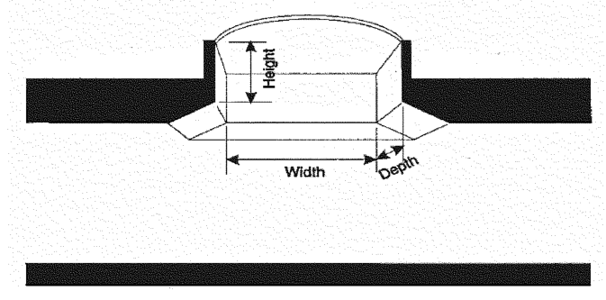
Figure C1.4 Skylight well dimensions.
C2.3 Location corresponding to the weather data used to perform the simulation.
C2.4 Simulation program used to perform the simulation.
C2.5 Tables summarizing the minimum information described in Section C1.
C2.6 All differences between the proposed envelope performance factor and the base envelope perfor- mance factor .
C2.7 Peak heating and cooling loads for building classes of constructions .
C2.8 The version of the software and the link to the website that contains the ASHRAE Standard 140 results for the version used in accordance with Section C3.1.4.
C2.9 For thermal bridges,
a. confirmation that the proposed design complies with the each of the requirements of Sections 5.5.5.1
through 5.5.5.5 including exceptions or b. where the proposed design does not comply with each of the individual requirements of Sections 5.5.5.1
through 5.5.5.5, list the thermal bridges, the proposed psi-factors, proposed chi-factors, and source information.
C3. SIMULATION GENERAL REQUIREMENTS
C3.1 Simulation Program. The simulation program shall be a computer-based software program for the analysis of energy consumption in buildings . The simulation program shall include calculation methodologies for the building components being modeled.
Informative Note: Examples of simulation programs include, but are not limited to, EnergyPlus and DOE-2.
C3.1.1 The simulation program shall be approved by the adopting authority and shall, at minimum, have the ability to explicitly model all of the following:
a. The base envelope performance factor, using only the input for the proposed envelope performance fac-
tor . The calculation procedure shall not allow the user to directly modify the building component characteristics of the base design. b. 8760 hours per year. c. Hourly variations in occupancy, lighting power, miscellaneous equipment power, thermostat set points,
and HVAC system operation, defined separately for each day of the week and holidays. d. Thermal mass effects. e. The number of thermal zones in the proposed design or nine thermal zones, whichever is greater. f. Air economizers with integrated control. g. Continuous daylight dimming controls and photosensors .
C3.1.2 The simulation program shall have the ability to determine the proposed envelope performance factor and base envelope performance factor by calculating annual energy costs.
Informative Note: Neither the proposed envelope performance factor nor the base envelope perfor- mance factor are predictions of actual energy consumption or costs for the proposed design after construc- tion . Actual experience will differ from these calculations due to variations such as occupancy, building
284 ANSI/ASHRAE/IES Standard 90.1-2022 (I-P)
PDF Page 287
operation and maintenance, weather, energy use not covered by this procedure, changes in energy rates between design of the building and occupancy, and the precision of the calculation tool.
C3.1.3 The simulation program shall be capable of performing design load calculations to determine required HVAC equipment capacities and airflow rates in accordance with Section 6.4.2 for both the pro- posed design building envelope and the base design building envelope .
C3.1.4 Simulation Program Testing Requirements
C3.1.4.1 The simulation program shall be tested according to ASHRAE Standard 140, except for Sections 7 and 8, of Standard 140. The required tests shall include building thermal envelope and fabric load tests (Sections 5.2.1, 5.2.2, and 5.2.3), ground coupled slab-on- grade analytical verification tests (Section 5.2.4), space -cooling equipment performance tests (Section 5.3), space -heating equipment performance tests (Section 5.4), and air-side HVAC equipment analytical verification tests (Section 5.5), along with the associated reporting (Section 6).
C3.1.4.2 The test results and modeler reports shall be posted on a publicly available website and shall include the test results of the simulation program and input files used for generating the results along with the results of the other simulation programs included in ASHRAE Standard 140, Annexes B8 and B16. The modeler report in Standard 140, Annex A2, Attachment A2.7 shall be completed for results exceeding the maximum or falling below the minimum of the reference values and for omitted results.
C3.1.4.3 The testing shall be performed for the version of the simulation program used to calculate the proposed envelope performance factor and base envelope performance factor .
Informative Notes:
- There are no pass/fail criteria established by this requirement.
- Based on the Section 3 definition, simulation program includes the simulation engine and the corresponding user interface. The testing of a simulation program only meets the requirements of Section C3.1.4 for that simulation program and cannot be used as proxy for documenting compliance of another simulation program that uses the same simulation engine .
C3.2 Climatic Data. The simulation program shall perform the simulation using hourly values of climatic data, including temperature, humidity, solar radiation, and wind speed and direction from representative climatic data, for the proposed design building envelope location. For cities or urban regions for which several climatic data sources are available and for locations for which weather data are not available, the designer shall select available weather data that represent the climate at the construction site . Selected weather data shall be approved by the authority having jurisdiction .
C3.2.1 Surface Exposure. Semiexterior surfaces separating conditioned spaces from unconditioned spaces shall be simulated as exterior surfaces with no exposure to wind or solar radiation.
C3.3 Purchased Energy Rates. The following rates for purchased energy shall be used to determine the proposed envelope performance factor and the base envelope performance factor :
a. Electricity: 0.98/therm
Exception to C3.3: Where approved by the authority having jurisdiction, actual annual rates for purchased
energy or state average energy prices published by the Department of Energy’s Energy Information Administration shall be permitted. The same rates shall be used for both the proposed envelope perfor- mance factor and the base envelope performance factor .
C3.4 Compliance Calculations. The proposed envelope performance factor and base envelope perfor- mance factor shall be calculated using the same
a. simulation program, b. climatic data, and c. purchased energy rates .
C3.5 Calculation of Proposed Envelope Performance Factor. The simulation model for calculating the proposed envelope performance factor shall be developed in accordance with Sections C3.5.1 through C3.5.11.
C3.5.1 Space Conditioning. All conditioned spaces in the proposed design shall be simulated as being both heated and cooled, even if no cooling or heating system is being installed. Temperature control set points and schedules shall be consistent with those in the building envelope trade-off schedules and loads for the applicable building area type. All semiheated spaces shall be simulated as being heated and not cooled. The heating temperature control set point shall be 50°F for all hours.
ANSI/ASHRAE/IES Standard 90.1-2022 (I-P) 285
PDF Page 288
C3.5.2 Model Geometry and Thermal Zones. The building model shall be divided into thermal zones described as follows:
a. Determine the ratio ( Rc ) of the floor area to the gross wall area for each unique combination of space
conditioning category and building area type. The index “c” refers to a combination of space condition- ing category and building area type as defined for each surface. b. Create a perimeter zone for each unique combination of building area type, above - grade - wall orienta-
tion, and space conditioning category . If there is more than one above - grade - wall assembly for a build- ing area type and orientation, each above - grade - wall assembly shall be placed end-to-end in the order it is defined. The area of each perimeter zone shall be the gross wall area of the zone times Rc or 1.25, whichever is smaller. c. For each unique combination of space conditioning category and building area type with Rc greater than
1.25, interior zones shall be created and used in the trade-off procedure. The area of the interior zone shall be the total area for the unique combination of space conditioning category and building area type less the area of the perimeter zones for that combination of space conditioning category and building area type. d. Create a below- grade zone for each unique combination of space conditioning category and building
area type associated with below-grade walls . If there is more than one below - grade - wall assembly for a building area type, each below- grade - wall assembly shall be placed end-to-end in the order it is defined. The area of each below- grade zone shall be the gross wall area of the zone times Rc or 1.25, whichever is smaller. e. The wall height and the height of each thermal zone shall be 15 ft. f. Roof area and floor area associated with each building area type shall be prorated among all zones of the corresponding building area type in proportion to the zone area of each zone. Roof area and floor area in each zone shall be centered in the horizontal plane of the zone with the same aspect ratio as the horizontal plane of the zone. g. Slab-on-grade floor perimeter associated with each building area type shall be prorated among perimeter
zones of the corresponding building area type in proportion to the area of each zone. h. Vertical fenestration area shall be assigned to the associated surface as described in Section C1.4. Verti-
cal fenestration shall be centered on the associated surface with the same aspect ratio as the associated surface. Windows with equivalent U-factor, SHGC, and VT that do not include fins may be combined into a single window on the associated surface. i. Skylight area shall be assigned to the associated surface as described in Section C1.4 and Figure C1.4, prorated among interior zones containing the roof area with which the skylight area is associated, in proportion to the associated roof area. If the total skylight area exceeds the associated roof area in interior zones, the remaining skylight area shall be prorated among perimeter zones containing the roof area with which the skylight area is associated, in proportion to the associated roof area. j. Each zone shall be modeled as being fully enclosed. Zone boundaries not created as described above shall be modeled as adiabatic interior surfaces.
C3.5.3 Daylight Area and Photosensor Location. Daylight areas and photosensors shall not be modeled in residential zones. In each nonresidential zone, daylight areas and photosensor locations shall be modeled in accordance with the following:
a. For each nonresidential zone associated with vertical fenestration, the daylight area shall be modeled as
directly adjacent to the vertical fenestration with a width equal to the width of the vertical fenestration and a depth equal to the head height of the vertical fenestration . b. In each nonresidential zone associated with skylights, the daylight area under skylights shall be modeled
as bounded, in each direction, by the edge of the skylight area plus 10 ft or the distance to the edge of the zone, whichever is less. c. For each daylight area associated with vertical fenestration, a photosensor shall be modeled as located at
the center of the width of the daylight area, at the depth of the daylight area and at a height of 3 ft. d. For each daylight area associated with a skylight, a photosensor shall be modeled as located at the center
of the horizontal plane of the skylight and at a height of 5 ft.
C3.5.4 Schedules. The schedule types listed in Section C3.1.1(c) shall be required input. The schedules shall be consistent with those in the building envelope trade-off schedules and loads [1] for the applicable building area type.
1 Schedules and internal loads by building area type are found at http://sspc901.ashraepcs.org/documents.php.
286 ANSI/ASHRAE/IES Standard 90.1-2022 (I-P)
PDF Page 289
C3.5.5 Building Envelope. The building envelope shall reflect the information specified in Section C1. Exception to C3.5.5: Where three-year-aged test data for the solar reflectance and three-year-aged ther mal emittance of the exterior roof surface are unavailable, the exterior roof surface shall be modeled with a solar reflectance of 0.30 and a thermal emittance of 0.90.
C3.5.5.1 Shading. Manually operated interior shades shall be modeled on all vertical fenestration . Shades shall be modeled to be in the lowered position when either the transmitted luminance is greater than 200 cd/ft [2] or the direct solar transmitted energy exceeds 30 Btu/h·ft [2] and then remain lowered for rest of the day. Shades shall be modeled with visible light transmittance of 0.10, visible light reflectance of 0.40, solar transmittance of 0.21, and solar reflectance of 0.23. Permanent shading devices such as fins and overhangs shall be modeled.
C3.5.5.2 Dynamic Glazing. Automatically controlled dynamic glazing is allowed to be modeled. Manually controlled dynamic glazing shall use the average of the minimum and maximum values for both SHGC and VT .
C3.5.5.3 Air Leakage. The air leakage rate of the building envelope ( I75Pa ) at a pressure differential of 75 Pa (0.30 in. of water) shall be 0.35 cfm/ft [2] of building envelope area when air leakage compliance is based on whole- building pressurization testing and shall be 0.45 cfm/ft [2] of building envelope area when air leakage compliance is based on verification. The air leakage of the building envelope shall be converted to the appropriate units to describe the air leakage as a function of the area of walls that separate conditioned spaces and semiheated spaces from the exterior as follows:
IAGW = 0.112 × I75Pa × S / AAGW where
I75Pa = air leakage rate of the building envelope (cfm/ft [2] ) at a fixed building pressure differential of 75 Pa (0.30 in. of water)
S = total area of the building envelope (ft [2] ) including the lowest floor, any below-grade walls or above-grade walls, and roof (including vertical fenestration and skylights )
IAGW = adjusted air leakage rate of the building envelope (cfm/ft [2] ) at a reference wind speed of 10 mph and relative to the area of the above-grade walls
AAGW = the total area of above-grade walls that comprise the building envelope, ft [2]
Exception to C3.5.5.3: If the simulation program cannot simulate air leakage as a function of the area
of walls that separate conditioned spaces and semiheated spaces from the exterior, the air leakage of the building envelope shall be converted to the appropriate units to describe the air leakage as a function of gross floor area as follows:
IFLR = 0.112 × I75Pa × S / AFLR where
IFLR = adjusted air leakage rate of the building envelope (cfm/ft [2] ) at a reference wind speed of 10 mph
and relative to the gross floor area
AFLR = gross floor area, ft [2]
C3.5.5.3.1 Air Leakage Schedule. To simulate air leakage as described in Section 5.4.3, infiltration shall be adjusted in accordance with the infiltration schedule in the building envelope trade-off schedules and loads for the applicable building area type.
C3.5.5.4 Thermal Bridges. Linear and point thermal bridges in the proposed design shall be either of the following:
a. Not modeled where option (a) or (c) is selected in Section C1.2.7. b. Entered as individual thermal bridge inputs of length or count where option (b) is selected in Section
C1.2.7 and addressed as follows:
- Individual thermal bridges in the proposed design that are indicated to comply with the requirements of Sections 5.5.5.1 through 5.5.5.5 need not be modeled.
- Individual thermal bridges in the proposed design that are indicated to not comply with the requirements of Sections 5.5.5.1 through 5.5.5.5 shall be modeled.
- Individual thermal bridges in the proposed design that are indicated to be not applicable with the requirements of Sections 5.5.5.1 through 5.5.5.5 need not be modeled. C3.5.6 Interior Surfaces. Interior surfaces shall be modeled with visible light reflectances of 0.80 for ceilings, 0.50 for walls, and 0.20 for floors. Interior surfaces shall be modeled with a thermal emittance of 0.90.
ANSI/ASHRAE/IES Standard 90.1-2022 (I-P) 287
PDF Page 290
C3.5.7 Lighting. The modeled lighting power shall be determined using the lighting power density allowances in Table 9.5.1 for the applicable building area type. The modeled lighting power shall be adjusted in accordance with the lighting schedule in the building envelope trade-off schedules and loads for the applicable building area type. Fifty percent (50%) of lighting in daylight areas shall be modeled with continuous daylight dimming controls such that when sufficient daylight is available at the corresponding photosensor, lighting power is reduced to maintain a minimum 50 fc for conditioned spaces and 30 fc for semiheated spaces . The minimum light output for the continuous daylight dimming shall be 6% of peak light output. Power input shall be modeled as 20% of lighting power at the minimum light output and scaled linearly to 100% of lighting power at peak light output. C3.5.8 HVAC Systems. One HVAC system shall be provided for each thermal zone and shall have the following characteristics:
a. Constant-volume fan control. b. Electrically provided cooling with EER from Table 6.8.1-1, based on requirements for split- system air
conditioners with heating section type “all other” between 65,000 Btu/h and 135,000 Btu/h. The EER shall be adjusted to remove the fan power in accordance with Section 12.5.2(c). c. Gas furnace with constant thermal efficiency equal to the minimum AFUE allowed for gas-fired warm air furnaces with maximum capacity <225,000 Btu/h, in accordance with Table 6.8.1-5. d. The ventilation rate for each building area type shall be consistent with the ventilation rate in the build-
ing envelope trade-off schedules and loads for the applicable building area type. e. Air economizers, except in Climate Zones 0 and 1. The high-limit shutoff shall be “Fixed Dry Bulb” type
as described in Table 6.5.1.1.3. f. System design supply air rates shall be based on a supply-air-to-room-air temperature difference of 20°F in cooling. g. System capacities used in the annual simulation shall be 1.5 times the capacities determined by the sizing
simulations. h. Fans shall cycle ON whenever the space calls for heating or cooling. The fan power shall be 0.3 W/cfm,
and the fan energy shall be modeled explicitly.
C3.5.9 Miscellaneous Loads. Miscellaneous loads shall be modeled as included in the building envelope trade-off schedules and loads for the applicable building area type.
C3.5.10 Occupant Density. The occupant density shall be modeled according to the peak occupant density and the occupancy rate schedule in the building envelope trade-off schedules and loads for the applicable building area type.
C3.5.11 Heat Gain from Occupants. The sensible and latent heat gain due to occupants shall be modeled as included in the building envelope trade-off schedules and loads for the applicable building area type.
C3.6 Calculation of Base Envelope Performance Factor. The simulation model for calculating the base envelope performance factor shall modify the simulation model for calculating the proposed envelope perfor- mance factor as follows:
a. All opaque assemblies shall be modeled with the U-factor not greater than that required in Section 5.5.3
for the appropriate class of construction, space conditioning category, and climate zone. Mass walls and mass floors shall be modeled with HC equal to 7.2 Btu/ft [2] ·°F. All other opaque assemblies shall be modeled with the same HC as the proposed design . Mass walls shall be modeled with equal mass on each side of the insulation. All other opaque assemblies shall be modeled with insulation on the exterior. b. Thermal bridges :
- Where option (a) is selected in Section C1.2.7, no modifications to the assembly U-factors are required.
- Where option (b) is selected in Section C1.2.7, the U-factor of the assembly interrupted shall be modified per Section A10.2 using the default values in Table A10.1 for the appropriate class of construc- tion . Each of the linear thermal bridges or point thermal bridges identified in Sections 5.5.5.1 through 5.5.5.5 shall be modeled in the simulation model for calculating the proposed envelope performance. Where the balcony length in the proposed design is greater than allowed by Section 5.5.5.2.2, the area shall be reduced proportionally along each exposure until the limit set in Section 5.5.5.2.2 is met.
- Where option (c) is selected in Section C1.2.7, no modifications to the assembly U-factors are required. c. The exterior roof surfaces shall be modeled with a solar reflectance and thermal emittance as required in
Section 5.5.3.1.4(a). All other roofs, including roofs exempted from the requirements in Section 5.5.3.1.4, shall be modeled the same as in the proposed design . The above-grade wall surfaces of buildings shall be
288 ANSI/ASHRAE/IES Standard 90.1-2022 (I-P)
PDF Page 291
modeled with a solar reflectance and thermal emittance as required in Section 5.5.3.2.2 and Section 5.5.3.2.2(a). All other above-grade walls, including those exempt from the requirements in Section 5.5.3.2.2, shall be modeled the same as the proposed design . d. Fenestration shall be assumed to be flush with the wall or roof . Fenestration U-factor and SHGC shall
be the maximum allowed for the appropriate class of construction, space conditioning category, and climate zone in accordance with Section 5.5.4. Where there is no SHGC requirement, the SHGC shall be equal to 0.40 for all vertical fenestration and 0.55 for skylights . The VT for fenestration in the base envelope design shall be equal to 1.10 times the SHGC . The fenestration area for new buildings or additions shall be modeled the same as the proposed building unless the following apply:
- Where the fenestration area exceeds the maximum allowed by Section 5.5.4.2, the area shall be reduced proportionally along each exposure until the limit set in Section 5.5.4.2 is met.
- Where the fenestration area facing west or east of the proposed design exceeds the area limit set in Section 5.5.4.5, the baseline building performance shall be generated by simulating the building with its actual orientation and again after rotating the entire building 90, 180, and 270 degrees and averaging the results of the four simulations.
- Where the Normative Appendix C calculation is being used to determine energy credits in accordance with Section 11.5.2.1, for building use types included in Table G3.1.1-1 where the proposed fenestration area is less than the value in Table G3.1.1-1, vertical fenestration areas shall equal that in Table G3.1.1-1 based on the area of gross above-grade walls that separate conditioned spaces and semiheated spaces from the exterior. Follow additional fenestration modeling requirements for base- line building performance in Table G3.1. e. Manually operated interior shades shall be modeled on all vertical fenestration as described in Section
C3.5.5.1. Permanent shading devices, such as fins and overhangs, shall not be modeled. f. Daylight areas and photosensor locations shall be modeled as described in Section C3.5.3 after reducing the fenestration area as described in Section C3.6(d). g. The air leakage rate of the building envelope ( I75Pa ) at a fixed building pressure differential of 75 Pa
(0.30 in. of water) shall be 0.35 cfm/ft [2] and shall be converted to units for the energy model using the same method as the proposed envelope performance factor .
ANSI/ASHRAE/IES Standard 90.1-2022 (I-P) 289
PDF Page 292
(This appendix is not part of this standard. It is merely informative and does not contain requirements necessary for conformance to the standard. It has not been processed according to the ANSI require- ments for a standard and may contain material that has not been subject to public review or a consen- sus process. Unresolved objectors on informative material are not offered the right to appeal at ASHRAE or ANSI.)
INFORMATIVE APPENDIX D (RETAINED FOR FUTURE USE)
Climatic data are no longer contained in this appendix. See Section 5.1.4 for requirements. Annex 1 of this standard contains extracts of material from ASHRAE Standard 169.
290 ANSI/ASHRAE/IES Standard 90.1-2022 (I-P)
PDF Page 293
(This appendix is not part of this standard. It is merely informative and does not contain requirements neces- sary for conformance to the standard. It has not been processed according to the ANSI requirements for a standard and may contain material that has not been subject to public review or a consensus process. Unre- solved objectors on informative material are not offered the right to appeal at ASHRAE or ANSI.)
INFORMATIVE APPENDIX E INFORMATIVE REFERENCES
This appendix contains informative references for the convenience of users of Standard 90.1 and to acknowledge source documents when appropriate. Some documents are also included in Section 13, “Normative References,” because there are other citations of those documents within the standard that are normative.
Address/Contact Information
Air Movement and Control Association (AMCA International, Inc.) 30 West University Drive Arlington Heights, IL 60004
American Society of Agricultural and Biological Engineers (ASABE) 2950 Niles Road St. Joseph, MI 49085
ASHRAE 180 Technology Parkway Peachtree Corners, GA 30092)
Associated Air Balance Council (AABC) 1015 18th St. NW Suite 603 Washington, DC 20036
ASTM International 100 Barr Harbor Drive P.O. Box C700 West Conshohocken, PA 19428-2959
BC Hydro Corporate Head Office 333 Dunsmuir Street Vancouver, B. C. V6B 5R3
Cooling Technology Institute (C TI) 3845 Cypress Creek Parkway, Suite 420 Houston, TX 77068 P.O. Box 681807, Houston, TX 77268
CWEC Climate Data Environment Canada Engineering Climate Datasets climate.weather.gc.ca/prods_servs/engineering_e.html
Hydraulic Institute (HI) 6 Campus Drive, First Floor North, Parsippany, NJ 07054-4405 pumps.org
Illuminating Engineering Society (IES) 120 Wall St. Fl 17 New York, NY 10005-4001 (212) 248-5000 www.ies.org
International Electechnical Commission (IEC) 3 rue de Varembé, PO Box 131, CH-1211 Geneva 20, Switzerland
International Standards Organization (ISO) Chemin de Blandonnet 8 CP 401-1214 Vernier, Geneva, Switzerland
Midwest Insulation Contractors Association (MICA) 16712 Elm Circle Omaha, NE 68130 www.micainsulation.org
National Environmental Balancing Bureau (NEBB) 8575 Grovemont Circle Gaithersburg, MD 20877 www.nebb.org
National Institute of Building Sciences (NIBS) 1090 Vermont Avenue NW, Suite 700 Washington, DC 20005-4950
National Renewable Energy Laboratory NREL/RReDC Attn: Pamela Gray-Hann 1617 Cole Blvd., MS-1612 Golden, Colorado, USA 80401
Sheet Metal and Air Conditioning Contractors SMACNA National Association 4201 Lafayette Center Drive Chantilly, VA 20151 www.smacna.org
ANSI/ASHRAE/IES Standard 90.1-2022 (I-P) 291
PDF Page 294
Reference Section
IES RP-8-18 Recommended Practice for Design and Maintenance of Roadway and Parking Facility Lighting
3.2
2021 ASHRAE Handbook—Fundamentals Appendix A, Chapter 26, or Chapter 33 5.5.5.5
NIBS Guideline 3-2012 Building Enclosure Commissioning Process BECx, Annex O 5.7.3.2, H1
ASTM E2947-21a Standard Guide for Building Enclosure Commissioning, Section 9.4
5.7.3.2, H1
ASTM E2947-21a Standard Guide for Building Enclosure Commissioning 5.9.1, H1
ASTM E2813-18 Standard Practice for Building Enclosure Commissioning 5.9.1, H1
CTI STD-201 OM (19) Operations Manual for Thermal Performance Certification of Evaporative Heat Rejection Equipment Cooling Technology Institute
6.4.1
MICA Insulation Standards, 9th Edition National Commercial and Industrial Insulation Standards 6.4.4.1.1
SMACNA Duct Construction Standards, 4th Ed. (2021) HVAC Duct Construction Standards, Metal and Flexible 6.4.4.2.1
SMACNA 016-2012 HVAC Air Duct Leakage Test Manual (Sections 3, 5, and 6) 6.4.4.2.2
ASHRAE Guideline 36-2021 High-Performance Sequences of Operation for HVAC Systems 6.5.3.8
ASHRAE Guideline 4-2019 Preparation of Operations and Maintenance Documentation for HVAC&R Systems
AABC, 7th Ed (2018) Associated Air Balance Council, National Standards for Total System Balance
ANSI/ASHRAE Standard 111-2008 (RA 2017) Measurement, Testing, Adjusting and Balancing of Building HVAC Systems
6.7.3.2
6.7.3.3.1
6.7.3.3.1
ANSI/ASHRAE Standard 202-2018 Commissioning Process for Buildings and Systems 6.9.2, H1
ASHRAE Guideline 0-2019 The Commissioning Process 6.9.2, H1
ASHRAE Guideline 1.1-2007 HVAC&R Technical Requirements for the Commissioning Process
6.9.2, H1
NEBB Procedural Standards, 9th Ed. (2019) Procedural Standards for Building Systems Commissioning 6.9.2
2019 ASHRAE Handbook—HVAC Applications Chapter 51, Service Water Heating/ASHRAE 7.4.1, 7.5
ANSI/ASHRAE Standard 188-2021 Legionellosis: Risk Management for Building water Systems 7.4.4
ASHRAE Guideline 12-2020 Managing the Risk of Legionellosis Associated with Building Water Systems
ANSI/ASABE S640-2017 Quantities and Units of Electromagnetic Radiation for Plants (Photosynthetic Organisms)
IES RP-6-20 Recommended Practice for Sports and Recreational Area Lighting
7.4.4
9.4.4
9.5.2
ANSI/IES RP-28-20 Lighting and the Visual Environment for Senior Living 9.5.2
ANSI/IES/AVIXA RP-38-17 Recommended Practice: Lighting Performance for Small to Medium Sized Videoconferencing Rooms
ISO 25745-2:2015 Energy performance of lifts, escalators and moving walks— Part 2: Energy calculation and classification for lifts (elevators)
ISO 27327-1:2012 Air Curtain Units—Part 1: Laboratory Methods of Testing for Aerodynamic Performance Rating
9.5.2, 9.5.2.2
10.4.3.4
10.4.5
292 ANSI/ASHRAE/IES Standard 90.1-2022 (I-P)
PDF Page 295
Reference Section
ANSI/AMCA Standard 220-05 (R2012) Laboratory Methods of Testing Air Curtain Units for Aerodynamic Performance Rating
ANSI/HI 1.1-1.2-2014 Rotodynamic Centrifugal Pumps for Nomenclature and Definitions
ANSI/HI 2.1-2.2-2014 Rotodynamic Vertical Pumps or Radial, Mixed, and Axial Flow Types for Nomenclature and Definitions
10.4.5
10.4.7
10.4.7
www.ies.org/standards/lighting-library/the-interactiveilluminance-selector (includes recommended illuminance levels from the following standards):
The Interactive Illuminance Selector 11.5.2.5
ANSI/IES RP-1-2020 Recommended Practice: Lighting Offices Spaces
ANSI/IES RP-2-2020 Recommended Practice: Lighting Retail Spaces
ANSI/IES RP-3-2020 Recommended Practice: Lighting Educational Facilities
ANSI/IES RP-4-2020 Recommended Practice: Lighting Library Spaces
ANSI/IES RP-6-2020 Recommended Practice: Lighting Sports and Recreational Areas
ANSI/IES RP-7-2020 Recommended Practice: Lighting Industrial Facilities
ANSI/IES RP-8-2021 Recommended Practice: Lighting Roadway and Parking Facilities
ANSI/IES RP-9-2020 Recommended Practice: Lighting Hospitality Spaces
ANSI/IES RP-10-2020 Recommended Practice: Lighting Common Applications
ANSI/IES RP-11-2020 Recommended Practice: Lighting for Interior and Exterior Residential Environments
ANSI/IES RP-28-2020 Recommended Practice: Lighting and the Visual Environment for Older Adults and the Visually Impaired
ANSI/IES RP-29-2020 Recommended Practice: Lighting Hospital and Healthcare Facilities
ANSI/IES RP-30-2020 Recommended Practice: Lighting Museums
ANSI/IES RP-38-2017 Recommended Practice: Lighting Performance for Small to Medium Sized Videoconferencing Rooms
ANSI/IES RP-41-2020 Recommended Practice: Lighting Theaters and Worship Spaces
IES Lighting Measurements (LM) 83-12 Approved Method: IES Spatial Daylight Autonomy (sDA) and Annual Sunlight Exposure (ASE)
ANSI/ASHRAE Standard 209-2018 Energy Simulation Aided Design for Buildings Except LowRise Residential Buildings
11.5.2.5.3
12.1.1, G1.2.2
CWEC Canadian Weather for Energy Calculations 12.4.2
IWEC2 (ASHRAE) International Weather for Energy Calculations, Generation 2 12.4.2
TMY3 Typical Meteorological Year, Generation 3 12.4.2
ASHRAE Transactions 101(2). Hogan, J.F. 1995. Approach for opaque envelope U-factors for ASHRAE/IESNA 90.1-1989R
A1.1
ASHRAE Handbook—Fundamentals (2021) A9.4
ASHRAE Transactions 116(1):10–017 Choudhary, M.K., C. Kasprzak, R.H. Larson, and R. Venuturumilli. 2010. ASHRAE Standard 90.1 metal building U-factors—Part 1: Mathematical modeling and validation by calibrated hot box measurements
A9.4.6
ANSI/ASHRAE/IES Standard 90.1-2022 (I-P) 293
PDF Page 296
Reference Section
ASHRAE Transactions 116(1):10–018 Choudhary, M.K., and C.P. Kasprzak. 2010. ASHRAE Standard 90.1 Metal building U-factors—Part 2: A system based approach for predicting the thermal performance of single layer fiberglass batt insulation assemblies
ASHRAE Transactions 116(1):10–019 McBride, M.F., and P.M. Gavin. 2010. ASHRAE Standard 90.1 metal building U-factors—Part 3: Equations for double layers of fiberglass batt insulation in roof and wall assemblies
ASHRAE Transactions 116(1):10–020 Christianson, L. 2010. ASHRAE Standard 90.1 metal building U-factors—Part 4: Metal building U-factors for walls and roof based on experimental measurements.
ASHRAE Transactions 118(1):12–006 Choudhary, M.K., C.P. Kasprzak, D.E. Musick, M.J. Henry, and N.D. Fast. 2012. ASHRAE Standard 90.1 metal building U-factors—Part 5: Mathematical modeling of wall assemblies and validation by calibrated hot box measurements
ASHRAE Transactions 122(1):16–014 Choudhary, M.K 2016. A general approach for predicting the thermal performance of metal building fiberglass insulation assemblies
A9.4.6
A9.4.6
A9.4.6
A9.4.6
A9.4.6
A10.1
Table A10.1
BC Hydro New Construction Program Orientation Manual (June 2016)
https://www.bchydro.com/powersmart/business/programs/ new-construction.html#thermal
ASHRAE Research Project 1365 The Impact of Thermal Bridges on Effective Thermal Resistance and Energy Use in Mid and High Rise Buildings
2021 ASHRAE Handbook—Fundamentals Chapter 19 G2.2.3
ISO/IEC 17024:2012 Community Assessment—General Requirements for Bodies Operating Certification of Persons
294 ANSI/ASHRAE/IES Standard 90.1-2022 (I-P)
H1
PDF Page 297
(This appendix is not part of this standard. It is merely informative and does not contain requirements necessary for conformance to the standard. It has not been processed according to the ANSI require- ments for a standard and may contain material that has not been subject to public review or a consen- sus process. Unresolved objectors on informative material are not offered the right to appeal at ASHRAE or ANSI.)
INFORMATIVE APPENDIX F U.S. DEPARTMENT OF ENERGY MINIMUM ENERGY EFFICIENCY REQUIREMENTS, TEST PROCEDURES, AND DEFINITIONS
In the United States, the U.S. Department of Energy (U.S. DOE) establishes efficiency standards for products that it defines as “residential covered products.” Since these products are used in buildings covered by this standard, U.S. DOE efficiency requirements are shown here for convenience. All U.S. DOE efficiency requirements for residential products are found in the U.S. Code of Federal Regulations, 10 CFR 430.32.
DOE also establishes definitions and test procedures for covered products. These are found in 10 CFR 430.2 and 10 CFR 430.23, respectively.
F1. U.S. DOE MINIMUM ENERGY EFFICIENCY REQUIREMENTS FOR SINGLE-PHASE AIR CONDITIONERS AND HEAT PUMPS
These standards became effective on January 1, 2015. In the United States, some of the standards are regional in nature. The U.S. has been divided into 3 regions: (a) the north, comprising states with a population weighted heating degree days (HDD) equal to or greater than 5000; (b) the southeast, comprising states with a population weighted HDD less than 5000; and (c) the southwest, comprising Arizona, California, Nevada, and New Mexico. The regions are shown in Figure F-1.
The U.S. federal minimum energy efficiency standards for single-phase air conditioners and heat pumps are shown in Table F-1. The standards apply to residential single-phase air conditioners and heat pumps that are rated at less than 65,000 Btu/h of cooling capacity.
F2. U.S. DOE MINIMUM ENERGY EFFICIENCY REQUIREMENTS FOR WATER HEATERS AND POOL HEATERS
These standards for Uniform Energy Factor became effective on December 29, 2017, and apply to products manufactured on or after that date and the thermal efficiency requirements for gas fired pool heaters manufactured on or after April 16, 2013 (Table F-2).
F3. U.S. DOE TEST PROCEDURE AND DEFINITIONS FOR CEILING FANS
U.S. DOE definitions for ceiling fans are found in 10 CFR 430.2 and 10 CFR Part 430, Subpart B, Appendix U. On or after January 23, 2017, manufacturers of ceiling fans must make any representations with respect to energy use or efficiency in accordance with the test procedure in 10 CFR Part 430, Subpart B, Appendix U. DOE also specifies, in 10 CFR 430.32, design requirements for ceiling fans, and for ceiling fans manufactured on or after January 21, 2020, minimum efficiency requirements.
ANSI/ASHRAE/IES Standard 90.1-2022 (I-P) 295
PDF Page 298
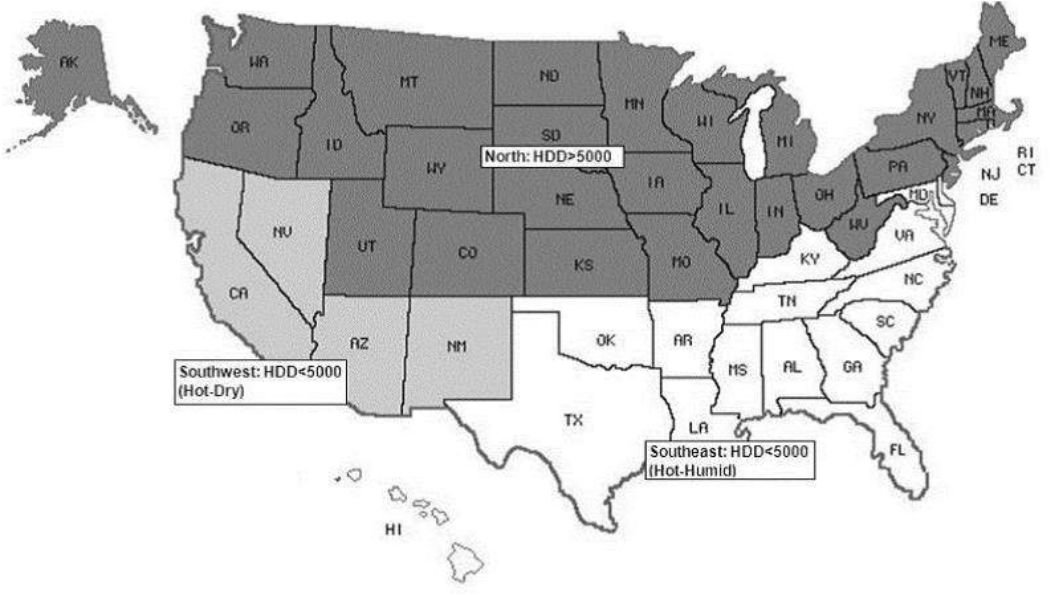
Figure F-1 Map of the regions for the analysis of central air conditioners and heat pumps. (Source: Federal Register 76 FR 37431, June 7, 2018)
Table F-1 Minimum Efficiency Requirements for Single-Phase Central Air Conditioners and Heat Pumps for Applications in the U.S.
| Split-system air conditioners for U.S. applications | <45,000 Btu/h single phase | SEER = 13.0 P 30 W W,OFF before 1/1/2023 SEER2 = 13.4 P 30 W W,OFF after 1/1/2023 | SEER = 14.0 P 30 W W,OFF before 1/1/2023 SEER2 = 14.3 P 30 W W,OFF after 1/1/2023 | SEER = 14.0 EER = 12.2 P 30 W W,OFF before 1/1/2023 SEER2 = 14.3 EER2 = 11.7/9.8 d P 30 W W,OFF after 1/1/2023 | AHRI 210/240-2017 before 1/1/2023 AHRI 210/240-2023 after 1/1/2023 |
|---|---|---|---|---|---|
| Split-system air conditioners | 45,000 Btu/h and <65,000 Btu/h single phase | SEER = 13.0 PW,OFF 30 W before 1/1/2023 SEER2 = 13.4 PW,OFF 30 W after 1/1/2023 | SEER = 14.0 PW,OFF 30 W before 1/1/2023 SEER2 = 13.8 PW,OFF 30 W after 1/1/2023 | SEER = 14.0 EER = 11.7d PW,OFF 30 W before 1/1/2023 SEER2 = 13.8 EER2 = 11.2/9.8e PW,OFF 30 W after 1/1/2023 | AHRI 210/240-2017 before 1/1/2023 AHRI 210/240-2023 after 1/1/2023 |
| a. The Southeastern region for central air conditioners and heat pumps contains the following States: Alabama, Arkansas, Delaware, Florida, Georgia, Hawaii, Kentucky, Louisiana, Maryland, Mississippi, North Carolina, Oklahoma, South Carolina, Tennessee, Texas, and Virginia, and the District of Columbia. b. The Southwestern region for central air conditioners contains the States of Arizona, California, Nevada, and New Mexico. c. SEER is_seasonal energy efficiency ratio_; EER is_energy efficiency ratio_; HSPF is_heating seasonal performance factor_; and Btu/h is British thermal units per hour.SEER2 is seasonal energy efficiency ratio reflecting the new higher static that is effective 1/1/2023;EER2 is_energy efficiency ratio_ also reflecting the higher static; and_HSPF2_ is new_heating_ seasonal performance factor reflecting the new higher static and load line. Test and rating procedure defined in AHRI 210/240-2017 for_EER_, SEER, and_HSPF_ and AHRI 210/ 240-2023 for_EER2_, SEER2, and_HSPF2_. The added “2” in the metric names reflects the new higher static (all metrics) and load line (HSPF2 only) for the new metrics effective 1/1/2023. d. The 11.7_EER2_ standard applies to products with a certified_SEER2_ less than 15.2. The 9.8_ EER2_ standard applies to products with a certified_SEER2_ greater than or equal to 15.2. e. The 11.2_EER2_ standard applies to products with a certified_SEER2_ less than 15.2. The 9.8_EER2_ standard applies to products with a certified_SEER2_ greater than or equal to 15.2. f. Section 13 contains a complete specification of the referenced test procedures, including the referenced year version of the test procedure. | a. The Southeastern region for central air conditioners and heat pumps contains the following States: Alabama, Arkansas, Delaware, Florida, Georgia, Hawaii, Kentucky, Louisiana, Maryland, Mississippi, North Carolina, Oklahoma, South Carolina, Tennessee, Texas, and Virginia, and the District of Columbia. b. The Southwestern region for central air conditioners contains the States of Arizona, California, Nevada, and New Mexico. c. SEER is_seasonal energy efficiency ratio_; EER is_energy efficiency ratio_; HSPF is_heating seasonal performance factor_; and Btu/h is British thermal units per hour.SEER2 is seasonal energy efficiency ratio reflecting the new higher static that is effective 1/1/2023;EER2 is_energy efficiency ratio_ also reflecting the higher static; and_HSPF2_ is new_heating_ seasonal performance factor reflecting the new higher static and load line. Test and rating procedure defined in AHRI 210/240-2017 for_EER_, SEER, and_HSPF_ and AHRI 210/ 240-2023 for_EER2_, SEER2, and_HSPF2_. The added “2” in the metric names reflects the new higher static (all metrics) and load line (HSPF2 only) for the new metrics effective 1/1/2023. d. The 11.7_EER2_ standard applies to products with a certified_SEER2_ less than 15.2. The 9.8_ EER2_ standard applies to products with a certified_SEER2_ greater than or equal to 15.2. e. The 11.2_EER2_ standard applies to products with a certified_SEER2_ less than 15.2. The 9.8_EER2_ standard applies to products with a certified_SEER2_ greater than or equal to 15.2. f. Section 13 contains a complete specification of the referenced test procedures, including the referenced year version of the test procedure. | a. The Southeastern region for central air conditioners and heat pumps contains the following States: Alabama, Arkansas, Delaware, Florida, Georgia, Hawaii, Kentucky, Louisiana, Maryland, Mississippi, North Carolina, Oklahoma, South Carolina, Tennessee, Texas, and Virginia, and the District of Columbia. b. The Southwestern region for central air conditioners contains the States of Arizona, California, Nevada, and New Mexico. c. SEER is_seasonal energy efficiency ratio_; EER is_energy efficiency ratio_; HSPF is_heating seasonal performance factor_; and Btu/h is British thermal units per hour.SEER2 is seasonal energy efficiency ratio reflecting the new higher static that is effective 1/1/2023;EER2 is_energy efficiency ratio_ also reflecting the higher static; and_HSPF2_ is new_heating_ seasonal performance factor reflecting the new higher static and load line. Test and rating procedure defined in AHRI 210/240-2017 for_EER_, SEER, and_HSPF_ and AHRI 210/ 240-2023 for_EER2_, SEER2, and_HSPF2_. The added “2” in the metric names reflects the new higher static (all metrics) and load line (HSPF2 only) for the new metrics effective 1/1/2023. d. The 11.7_EER2_ standard applies to products with a certified_SEER2_ less than 15.2. The 9.8_ EER2_ standard applies to products with a certified_SEER2_ greater than or equal to 15.2. e. The 11.2_EER2_ standard applies to products with a certified_SEER2_ less than 15.2. The 9.8_EER2_ standard applies to products with a certified_SEER2_ greater than or equal to 15.2. f. Section 13 contains a complete specification of the referenced test procedures, including the referenced year version of the test procedure. | a. The Southeastern region for central air conditioners and heat pumps contains the following States: Alabama, Arkansas, Delaware, Florida, Georgia, Hawaii, Kentucky, Louisiana, Maryland, Mississippi, North Carolina, Oklahoma, South Carolina, Tennessee, Texas, and Virginia, and the District of Columbia. b. The Southwestern region for central air conditioners contains the States of Arizona, California, Nevada, and New Mexico. c. SEER is_seasonal energy efficiency ratio_; EER is_energy efficiency ratio_; HSPF is_heating seasonal performance factor_; and Btu/h is British thermal units per hour.SEER2 is seasonal energy efficiency ratio reflecting the new higher static that is effective 1/1/2023;EER2 is_energy efficiency ratio_ also reflecting the higher static; and_HSPF2_ is new_heating_ seasonal performance factor reflecting the new higher static and load line. Test and rating procedure defined in AHRI 210/240-2017 for_EER_, SEER, and_HSPF_ and AHRI 210/ 240-2023 for_EER2_, SEER2, and_HSPF2_. The added “2” in the metric names reflects the new higher static (all metrics) and load line (HSPF2 only) for the new metrics effective 1/1/2023. d. The 11.7_EER2_ standard applies to products with a certified_SEER2_ less than 15.2. The 9.8_ EER2_ standard applies to products with a certified_SEER2_ greater than or equal to 15.2. e. The 11.2_EER2_ standard applies to products with a certified_SEER2_ less than 15.2. The 9.8_EER2_ standard applies to products with a certified_SEER2_ greater than or equal to 15.2. f. Section 13 contains a complete specification of the referenced test procedures, including the referenced year version of the test procedure. | a. The Southeastern region for central air conditioners and heat pumps contains the following States: Alabama, Arkansas, Delaware, Florida, Georgia, Hawaii, Kentucky, Louisiana, Maryland, Mississippi, North Carolina, Oklahoma, South Carolina, Tennessee, Texas, and Virginia, and the District of Columbia. b. The Southwestern region for central air conditioners contains the States of Arizona, California, Nevada, and New Mexico. c. SEER is_seasonal energy efficiency ratio_; EER is_energy efficiency ratio_; HSPF is_heating seasonal performance factor_; and Btu/h is British thermal units per hour.SEER2 is seasonal energy efficiency ratio reflecting the new higher static that is effective 1/1/2023;EER2 is_energy efficiency ratio_ also reflecting the higher static; and_HSPF2_ is new_heating_ seasonal performance factor reflecting the new higher static and load line. Test and rating procedure defined in AHRI 210/240-2017 for_EER_, SEER, and_HSPF_ and AHRI 210/ 240-2023 for_EER2_, SEER2, and_HSPF2_. The added “2” in the metric names reflects the new higher static (all metrics) and load line (HSPF2 only) for the new metrics effective 1/1/2023. d. The 11.7_EER2_ standard applies to products with a certified_SEER2_ less than 15.2. The 9.8_ EER2_ standard applies to products with a certified_SEER2_ greater than or equal to 15.2. e. The 11.2_EER2_ standard applies to products with a certified_SEER2_ less than 15.2. The 9.8_EER2_ standard applies to products with a certified_SEER2_ greater than or equal to 15.2. f. Section 13 contains a complete specification of the referenced test procedures, including the referenced year version of the test procedure. | a. The Southeastern region for central air conditioners and heat pumps contains the following States: Alabama, Arkansas, Delaware, Florida, Georgia, Hawaii, Kentucky, Louisiana, Maryland, Mississippi, North Carolina, Oklahoma, South Carolina, Tennessee, Texas, and Virginia, and the District of Columbia. b. The Southwestern region for central air conditioners contains the States of Arizona, California, Nevada, and New Mexico. c. SEER is_seasonal energy efficiency ratio_; EER is_energy efficiency ratio_; HSPF is_heating seasonal performance factor_; and Btu/h is British thermal units per hour.SEER2 is seasonal energy efficiency ratio reflecting the new higher static that is effective 1/1/2023;EER2 is_energy efficiency ratio_ also reflecting the higher static; and_HSPF2_ is new_heating_ seasonal performance factor reflecting the new higher static and load line. Test and rating procedure defined in AHRI 210/240-2017 for_EER_, SEER, and_HSPF_ and AHRI 210/ 240-2023 for_EER2_, SEER2, and_HSPF2_. The added “2” in the metric names reflects the new higher static (all metrics) and load line (HSPF2 only) for the new metrics effective 1/1/2023. d. The 11.7_EER2_ standard applies to products with a certified_SEER2_ less than 15.2. The 9.8_ EER2_ standard applies to products with a certified_SEER2_ greater than or equal to 15.2. e. The 11.2_EER2_ standard applies to products with a certified_SEER2_ less than 15.2. The 9.8_EER2_ standard applies to products with a certified_SEER2_ greater than or equal to 15.2. f. Section 13 contains a complete specification of the referenced test procedures, including the referenced year version of the test procedure. |
296 ANSI/ASHRAE/IES Standard 90.1-2022 (I-P)
PDF Page 299
Table F-1 Minimum Efficiency Requirements for Single-Phase Central Air Conditioners and Heat Pumps for Applications in the U.S.
| Split-system heat pumps | <65,000 Btu/h single phase | SEER = 14.0 HSPF = 8.2 P 33 W W,OFF before 1/1/2023 SEER2 = 14.3 HSPF2 = 7.5 P 33 W W,OFF after 1/1/2023 | SEER = 14.0 HSPF = 8.2 P 33 W W,OFF before 1/1/2023 SEER2 = 14.3 HSPF2 = 7.5 P 33 W W,OFF after 1/1/2023 | SEER = 14.0 HSPF = 8.2 P 33 W W,OFF before 1/1/2023 SEER2 = 14.3 HSPF2 = 7.5 P 33 W W,OFF after 1/1/2023 | AHRI 210/240-2017 before 1/1/2023 AHRI 210/240-2023 after 1/1/2023 |
|---|---|---|---|---|---|
| Single-package air conditioners | <65,000 Btu/h single phase | SEER = 14.0 PW,OFF 30 W before 1/1/2023 SEER2 = 13.4 PW,OFF 30 W after 1/1/2023 | SEER = 14.0 PW,OFF 30 W before 1/1/2023 SEER2 = 13.4 PW,OFF 30 W after 1/1/2023 | SEER = 14.0 EER = 11.0 PW,OFF 30 W before 1/1/2023 SEER2 = 13.4 EER2 = 10.6 PW,OFF 30 W after 1/1/2023 | AHRI 210/240-2017 before 1/1/2023 AHRI 210/240-2023 after 1/1/2023 |
| Single-package heat pumps | <65,000 Btu/h single phase | SEER = 14.0 HSPF = 8.0 PW,OFF 33 W before 1/1/2023 SEER2 = 13.4 HSPF2 = 6.7 PW,OFF 33 W after 1/1/2023 | SEER = 14.0 HSPF = 8.0 PW,OFF 33 W before 1/1/2023 SEER2 = 13.4 HSPF2 = 6.7 PW,OFF 33 W after 1/1/2023 | SEER = 14.0 HSPF = 8.0 PW,OFF 33 W before 1/1/2023 SEER2 = 13.4 HSPF2 = 6.7 PW,OFF 33 W after 1/1/2023 | AHRI 210/240-2017 before 1/1/2023 AHRI 210/240-2023 after 1/1/2023 |
| Small-duct high-velocity_systems_ | <65,000 Btu/h single phase | SEER = 12.0 HSPF = 7.2 PW,OFF 30 W before 1/1/2023 SEER2 = 12.0 HSPF2 = 6.1 PW,OFF 30 W after 1/1/2023 | SEER = 12.0 HSPF = 7.2 PW,OFF 30 W before 1/1/2023 SEER2 = 12.0 HSPF2 = 6.1 PW,OFF 30 W after 1/1/2023 | SEER = 12.0 HSPF = 7.2 PW,OFF 30 W before 1/1/2023 SEER2 = 12.0 HSPF2 = 6.1 PW,OFF 30 W after 1/1/2023 | AHRI 210/240-2017 before 1/1/2023 AHRI 210/240-2023 after 1/1/2023 |
| Space-constrained products— air conditioners a | <65,000 Btu/h single phase | SEER = 12.0 PW,OFF 30 W before 1/1/2023 SEER2 = 11.7 PW,OFF 30 W after 1/1/2023 | SEER = 12.0 PW,OFF 30 W before 1/1/2023 SEER2 = 11.7 PW,OFF 30 W after 1/1/2023 | SEER = 12.0 PW,OFF 30 W before 1/1/2023 SEER2 = 11.7 PW,OFF 30 W after 1/1/2023 | AHRI 210/240-2017 before 1/1/2023 AHRI 210/240-2023 after 1/1/2023 |
| Space-constrained products— heat pumps a | <65,000 Btu/h single phase | SEER = 12.0 HSPF = 7.4 PW,OFF 33 W before 1/1/2023 SEER2 = 11.9 HSPF2 = 6.3 PW,OFF 33 W after 1/1/2023 | SEER = 12.0 HSPF = 7.4 PW,OFF 33 W before 1/1/2023 SEER2 = 11.9 HSPF2 = 6.3 PW,OFF 33 W after 1/1/2023 | SEER = 12.0 HSPF = 7.4 PW,OFF 33 W before 1/1/2023 SEER2 = 11.9 HSPF2 = 6.3 PW,OFF 33 W after 1/1/2023 | AHRI 210/240-2017 before 1/1/2023 AHRI 210/240-2023 after 1/1/2023 |
| a. The Southeastern region for central air conditioners and heat pumps contains the following States: Alabama, Arkansas, Delaware, Florida, Georgia, Hawaii, Kentucky, Louisiana, Maryland, Mississippi, North Carolina, Oklahoma, South Carolina, Tennessee, Texas, and Virginia, and the District of Columbia. b. The Southwestern region for central air conditioners contains the States of Arizona, California, Nevada, and New Mexico. c. SEER is_seasonal energy efficiency ratio_; EER is_energy efficiency ratio_; HSPF is_heating seasonal performance factor_; and Btu/h is British thermal units per hour.SEER2 is seasonal energy efficiency ratio reflecting the new higher static that is effective 1/1/2023;EER2 is_energy efficiency ratio_ also reflecting the higher static; and_HSPF2_ is new_heating_ seasonal performance factor reflecting the new higher static and load line. Test and rating procedure defined in AHRI 210/240-2017 for_EER_, SEER, and_HSPF_ and AHRI 210/ 240-2023 for_EER2_, SEER2, and_HSPF2_. The added “2” in the metric names reflects the new higher static (all metrics) and load line (HSPF2 only) for the new metrics effective 1/1/2023. d. The 11.7_EER2_ standard applies to products with a certified_SEER2_ less than 15.2. The 9.8_ EER2_ standard applies to products with a certified_SEER2_ greater than or equal to 15.2. e. The 11.2_EER2_ standard applies to products with a certified_SEER2_ less than 15.2. The 9.8_EER2_ standard applies to products with a certified_SEER2_ greater than or equal to 15.2. f. Section 13 contains a complete specification of the referenced test procedures, including the referenced year version of the test procedure. | a. The Southeastern region for central air conditioners and heat pumps contains the following States: Alabama, Arkansas, Delaware, Florida, Georgia, Hawaii, Kentucky, Louisiana, Maryland, Mississippi, North Carolina, Oklahoma, South Carolina, Tennessee, Texas, and Virginia, and the District of Columbia. b. The Southwestern region for central air conditioners contains the States of Arizona, California, Nevada, and New Mexico. c. SEER is_seasonal energy efficiency ratio_; EER is_energy efficiency ratio_; HSPF is_heating seasonal performance factor_; and Btu/h is British thermal units per hour.SEER2 is seasonal energy efficiency ratio reflecting the new higher static that is effective 1/1/2023;EER2 is_energy efficiency ratio_ also reflecting the higher static; and_HSPF2_ is new_heating_ seasonal performance factor reflecting the new higher static and load line. Test and rating procedure defined in AHRI 210/240-2017 for_EER_, SEER, and_HSPF_ and AHRI 210/ 240-2023 for_EER2_, SEER2, and_HSPF2_. The added “2” in the metric names reflects the new higher static (all metrics) and load line (HSPF2 only) for the new metrics effective 1/1/2023. d. The 11.7_EER2_ standard applies to products with a certified_SEER2_ less than 15.2. The 9.8_ EER2_ standard applies to products with a certified_SEER2_ greater than or equal to 15.2. e. The 11.2_EER2_ standard applies to products with a certified_SEER2_ less than 15.2. The 9.8_EER2_ standard applies to products with a certified_SEER2_ greater than or equal to 15.2. f. Section 13 contains a complete specification of the referenced test procedures, including the referenced year version of the test procedure. | a. The Southeastern region for central air conditioners and heat pumps contains the following States: Alabama, Arkansas, Delaware, Florida, Georgia, Hawaii, Kentucky, Louisiana, Maryland, Mississippi, North Carolina, Oklahoma, South Carolina, Tennessee, Texas, and Virginia, and the District of Columbia. b. The Southwestern region for central air conditioners contains the States of Arizona, California, Nevada, and New Mexico. c. SEER is_seasonal energy efficiency ratio_; EER is_energy efficiency ratio_; HSPF is_heating seasonal performance factor_; and Btu/h is British thermal units per hour.SEER2 is seasonal energy efficiency ratio reflecting the new higher static that is effective 1/1/2023;EER2 is_energy efficiency ratio_ also reflecting the higher static; and_HSPF2_ is new_heating_ seasonal performance factor reflecting the new higher static and load line. Test and rating procedure defined in AHRI 210/240-2017 for_EER_, SEER, and_HSPF_ and AHRI 210/ 240-2023 for_EER2_, SEER2, and_HSPF2_. The added “2” in the metric names reflects the new higher static (all metrics) and load line (HSPF2 only) for the new metrics effective 1/1/2023. d. The 11.7_EER2_ standard applies to products with a certified_SEER2_ less than 15.2. The 9.8_ EER2_ standard applies to products with a certified_SEER2_ greater than or equal to 15.2. e. The 11.2_EER2_ standard applies to products with a certified_SEER2_ less than 15.2. The 9.8_EER2_ standard applies to products with a certified_SEER2_ greater than or equal to 15.2. f. Section 13 contains a complete specification of the referenced test procedures, including the referenced year version of the test procedure. | a. The Southeastern region for central air conditioners and heat pumps contains the following States: Alabama, Arkansas, Delaware, Florida, Georgia, Hawaii, Kentucky, Louisiana, Maryland, Mississippi, North Carolina, Oklahoma, South Carolina, Tennessee, Texas, and Virginia, and the District of Columbia. b. The Southwestern region for central air conditioners contains the States of Arizona, California, Nevada, and New Mexico. c. SEER is_seasonal energy efficiency ratio_; EER is_energy efficiency ratio_; HSPF is_heating seasonal performance factor_; and Btu/h is British thermal units per hour.SEER2 is seasonal energy efficiency ratio reflecting the new higher static that is effective 1/1/2023;EER2 is_energy efficiency ratio_ also reflecting the higher static; and_HSPF2_ is new_heating_ seasonal performance factor reflecting the new higher static and load line. Test and rating procedure defined in AHRI 210/240-2017 for_EER_, SEER, and_HSPF_ and AHRI 210/ 240-2023 for_EER2_, SEER2, and_HSPF2_. The added “2” in the metric names reflects the new higher static (all metrics) and load line (HSPF2 only) for the new metrics effective 1/1/2023. d. The 11.7_EER2_ standard applies to products with a certified_SEER2_ less than 15.2. The 9.8_ EER2_ standard applies to products with a certified_SEER2_ greater than or equal to 15.2. e. The 11.2_EER2_ standard applies to products with a certified_SEER2_ less than 15.2. The 9.8_EER2_ standard applies to products with a certified_SEER2_ greater than or equal to 15.2. f. Section 13 contains a complete specification of the referenced test procedures, including the referenced year version of the test procedure. | a. The Southeastern region for central air conditioners and heat pumps contains the following States: Alabama, Arkansas, Delaware, Florida, Georgia, Hawaii, Kentucky, Louisiana, Maryland, Mississippi, North Carolina, Oklahoma, South Carolina, Tennessee, Texas, and Virginia, and the District of Columbia. b. The Southwestern region for central air conditioners contains the States of Arizona, California, Nevada, and New Mexico. c. SEER is_seasonal energy efficiency ratio_; EER is_energy efficiency ratio_; HSPF is_heating seasonal performance factor_; and Btu/h is British thermal units per hour.SEER2 is seasonal energy efficiency ratio reflecting the new higher static that is effective 1/1/2023;EER2 is_energy efficiency ratio_ also reflecting the higher static; and_HSPF2_ is new_heating_ seasonal performance factor reflecting the new higher static and load line. Test and rating procedure defined in AHRI 210/240-2017 for_EER_, SEER, and_HSPF_ and AHRI 210/ 240-2023 for_EER2_, SEER2, and_HSPF2_. The added “2” in the metric names reflects the new higher static (all metrics) and load line (HSPF2 only) for the new metrics effective 1/1/2023. d. The 11.7_EER2_ standard applies to products with a certified_SEER2_ less than 15.2. The 9.8_ EER2_ standard applies to products with a certified_SEER2_ greater than or equal to 15.2. e. The 11.2_EER2_ standard applies to products with a certified_SEER2_ less than 15.2. The 9.8_EER2_ standard applies to products with a certified_SEER2_ greater than or equal to 15.2. f. Section 13 contains a complete specification of the referenced test procedures, including the referenced year version of the test procedure. | a. The Southeastern region for central air conditioners and heat pumps contains the following States: Alabama, Arkansas, Delaware, Florida, Georgia, Hawaii, Kentucky, Louisiana, Maryland, Mississippi, North Carolina, Oklahoma, South Carolina, Tennessee, Texas, and Virginia, and the District of Columbia. b. The Southwestern region for central air conditioners contains the States of Arizona, California, Nevada, and New Mexico. c. SEER is_seasonal energy efficiency ratio_; EER is_energy efficiency ratio_; HSPF is_heating seasonal performance factor_; and Btu/h is British thermal units per hour.SEER2 is seasonal energy efficiency ratio reflecting the new higher static that is effective 1/1/2023;EER2 is_energy efficiency ratio_ also reflecting the higher static; and_HSPF2_ is new_heating_ seasonal performance factor reflecting the new higher static and load line. Test and rating procedure defined in AHRI 210/240-2017 for_EER_, SEER, and_HSPF_ and AHRI 210/ 240-2023 for_EER2_, SEER2, and_HSPF2_. The added “2” in the metric names reflects the new higher static (all metrics) and load line (HSPF2 only) for the new metrics effective 1/1/2023. d. The 11.7_EER2_ standard applies to products with a certified_SEER2_ less than 15.2. The 9.8_ EER2_ standard applies to products with a certified_SEER2_ greater than or equal to 15.2. e. The 11.2_EER2_ standard applies to products with a certified_SEER2_ less than 15.2. The 9.8_EER2_ standard applies to products with a certified_SEER2_ greater than or equal to 15.2. f. Section 13 contains a complete specification of the referenced test procedures, including the referenced year version of the test procedure. |
ANSI/ASHRAE/IES Standard 90.1-2022 (I-P) 297
PDF Page 300
Table F-2 Minimum Energy Efficiency Requirements for Water Heaters and Pool Heaters Source: 10 CFR Part 430, Energy Conservation Program: Energy Conservation Standards for Water Heaters
| Product Class | Rated Storage Volume and input Rating (if applicable) | Draw Pattern | Uniform Energy Factor (UEF) or Thermal Efficiency (E) t | Test Procedure |
|---|---|---|---|---|
| Gas-fired storage water heater | 20 gal and55 gal | Very small | UEF = 0.3456 – (0.0020 ×Vr) | 10 CFR 430 Appendix E |
| Gas-fired storage water heater | 20 gal and55 gal | Low | UEF = 0.5982 – (0.0019 ×Vr) | UEF = 0.5982 – (0.0019 ×Vr) |
| Gas-fired storage water heater | 20 gal and55 gal | Medium | UEF = 0.6483 – (0.0017 ×Vr) | UEF = 0.6483 – (0.0017 ×Vr) |
| Gas-fired storage water heater | 20 gal and55 gal | High | UEF = 0.6920 – (0.0013 ×Vr) | UEF = 0.6920 – (0.0013 ×Vr) |
| Gas-fired storage water heater | >55 gal and100 gal | Very small | UEF = 0.6470 – (0.0006 ×Vr) | 10 CFR 430 Appendix E |
| Gas-fired storage water heater | >55 gal and100 gal | Low | UEF = 0.7689 – (0.0005 ×Vr) | UEF = 0.7689 – (0.0005 ×Vr) |
| Gas-fired storage water heater | >55 gal and100 gal | Medium | UEF = 0.7897 – (0.0004 ×Vr) | UEF = 0.7897 – (0.0004 ×Vr) |
| Gas-fired storage water heater | >55 gal and100 gal | High | UEF = 0.8072 – (0.0003 ×Vr) | UEF = 0.8072 – (0.0003 ×Vr) |
| Oil-fired storage water heater | 50 gal | Very small | UEF = 0.2509 – (0.0012 ×Vr) | 10 CFR 430 Appendix E |
| Oil-fired storage water heater | 50 gal | Low | UEF = 0.5330 – (0.0016 ×Vr) | UEF = 0.5330 – (0.0016 ×Vr) |
| Oil-fired storage water heater | 50 gal | Medium | UEF = 0.6078 – (0.0016 ×Vr) | UEF = 0.6078 – (0.0016 ×Vr) |
| Oil-fired storage water heater | 50 gal | High | UEF = 0.6815 – (0.0014 ×Vr) | UEF = 0.6815 – (0.0014 ×Vr) |
| Electric storage water heaters | 20 gal and55 gal | Very small | UEF = 0.8808 – (0.0008 ×Vr) | 10 CFR 430 Appendix E |
| Electric storage water heaters | 20 gal and55 gal | Low | UEF = 0.9254 – (0.0003 ×Vr) | UEF = 0.9254 – (0.0003 ×Vr) |
| Electric storage water heaters | 20 gal and55 gal | Medium | UEF = 0.9307 – (0.0002 ×Vr) | UEF = 0.9307 – (0.0002 ×Vr) |
| Electric storage water heaters | 20 gal and55 gal | High | UEF = 0.9349 – (0.0001 ×Vr) | UEF = 0.9349 – (0.0001 ×Vr) |
| Electric storage water heaters | >55 gal and120 gal | Very small | UEF = 1.9236 – (0.0011 ×Vr) | 10 CFR 430 Appendix E |
| Electric storage water heaters | >55 gal and120 gal | Low | UEF = 2.0440 – (0.0011 ×Vr) | UEF = 2.0440 – (0.0011 ×Vr) |
| Electric storage water heaters | >55 gal and120 gal | Medium | UEF = 2.1171 – (0.0011 ×Vr) | UEF = 2.1171 – (0.0011 ×Vr) |
| Electric storage water heaters | >55 gal and120 gal | High | UEF = 2.2418 – (0.0011 ×Vr) | UEF = 2.2418 – (0.0011 ×Vr) |
| Tabletop water heater | 20 gal and120 gal | Very small | UEF = 0.6323 – (0.0058 ×Vr) | 10 CFR 430 Appendix E |
| Tabletop water heater | 20 gal and120 gal | Low | UEF = 0.9188 – (0.0031 ×Vr) | UEF = 0.9188 – (0.0031 ×Vr) |
| Tabletop water heater | 20 gal and120 gal | Medium | UEF = 0.9577 – (0.0023 ×Vr) | UEF = 0.9577 – (0.0023 ×Vr) |
| Tabletop water heater | 20 gal and120 gal | High | UEF = 0.9884 – (0.0016 ×Vr) | UEF = 0.9884 – (0.0016 ×Vr) |
| Instantaneous gas-fired water heater | <2 gal and >50,000 Btu/h | Very small | UEF = 0.80 | 10 CFR 430 Appendix E |
| Instantaneous gas-fired water heater | <2 gal and >50,000 Btu/h | Low | UEF = 0.81 | UEF = 0.81 |
| Instantaneous gas-fired water heater | <2 gal and >50,000 Btu/h | Medium | UEF = 0.81 | UEF = 0.81 |
| Instantaneous gas-fired water heater | <2 gal and >50,000 Btu/h | High | UEF = 0.81 | UEF = 0.81 |
| Instantaneous electric water heater | <2 gal | Very small | UEF = 0.91 | 10 CFR 430 Appendix E |
| Instantaneous electric water heater | <2 gal | Low | UEF = 0.91 | UEF = 0.91 |
| Instantaneous electric water heater | <2 gal | Medium | UEF = 0.91t | UEF = 0.91t |
| Instantaneous electric water heater | <2 gal | High | UEF = 0.92 | UEF = 0.92 |
| Grid-enabled water heaters | >75 gal | Very small | UEF = 1.0136 – (0.0028 ×Vr) | 10 CFR 430 Appendix E |
| Grid-enabled water heaters | >75 gal | Low | UEF = 0.9984 – (0.0014 ×Vr) | UEF = 0.9984 – (0.0014 ×Vr) |
| Grid-enabled water heaters | >75 gal | Medium | UEF = 0.9853 – (0.0010 ×Vr) | UEF = 0.9853 – (0.0010 ×Vr) |
| Grid-enabled water heaters | >75 gal | High | UEF = 0.9720 – (0.0007 ×Vr) | UEF = 0.9720 – (0.0007 ×Vr) |
| Pool heater gas | 82%_ Et_ | 10 CFR 430 Appendix P |
a. Vr is the rated storage volume (in gallons), as determined pursuant to 10 CFR 429.17. b. Standards for electric storage water heaters apply to both electric resistance water heaters and heat-pump water heaters.
298 ANSI/ASHRAE/IES Standard 90.1-2022 (I-P)
PDF Page 301
Table F-3 Minimum Efficiency Requirements for Room Air Conditioners for U.S. Applications
| Product Class | Capacity Range | Efficiency Requirementsa | Test Procedureb |
|---|---|---|---|
| Room air conditioners without reverse cycle with louvered sides | <6,000 Btu/h | CEER = 11.0 | 10 CFR 430 Appendix F |
| Room air conditioners without reverse cycle with louvered sides | 6,000 Btu/h and <8,000 Btu/h | CEER = 11.0 | CEER = 11.0 |
| Room air conditioners without reverse cycle with louvered sides | 8,000 Btu/h and <14,000 Btu/h | CEER= 10.9 | CEER= 10.9 |
| Room air conditioners without reverse cycle with louvered sides | 14,000 Btu/h and <20,000 Btu/h | CEER = 10.7 | CEER = 10.7 |
| Room air conditioners without reverse cycle with louvered sides | 20,000 Btu/h and <28,000 Btu/h | CEER = 9.4 | CEER = 9.4 |
| Room air conditioners without reverse cycle with louvered sides | 28,000 Btu/h | CEER= 9.0 | CEER= 9.0 |
| Room air conditioners without reverse cycle without louvered sides | <6,000 Btu/h | CEER = 10.0 | 10 CFR 430 Appendix F |
| Room air conditioners without reverse cycle without louvered sides | 6,000 Btu/h and <8,000 Btu/h | CEER = 10.0 | CEER = 10.0 |
| Room air conditioners without reverse cycle without louvered sides | 8,000 Btu/h and <11,000 Btu/h | CEER= 9.6 | CEER= 9.6 |
| Room air conditioners without reverse cycle without louvered sides | 11,000 Btu/h and <14,000 Btu/h | CEER = 9.5 | CEER = 9.5 |
| Room air conditioners without reverse cycle without louvered sides | 14,000 Btu/h and <20,000 Btu/h | CEER = 9.3 | CEER = 9.3 |
| Room air conditioners without reverse cycle without louvered sides | 20,000 Btu/h | CEER= 9.4 | CEER= 9.4 |
| Room air conditioners with reverse cycle with louvered sides | <20,000 Btu/h | CEER= 9.8 | 10 CFR 430 Appendix F |
| Room air conditioners with reverse cycle with louvered sides | 20,000 Btu/h | CEER= 9.3 | CEER= 9.3 |
| Room air conditioners with reverse cycle without louvered sides | <14,000 Btu/h | CEER= 9.3 | 10 CFR 430 Appendix F |
| Room air conditioners with reverse cycle without louvered sides | 14,000 Btu/h | CEER= 8.7 | CEER= 8.7 |
| Room air conditioners, casement only | All | CEER= 9.5 | 10 CFR 430 Appendix F |
| Room air conditioners, casement slider | All | CEER= 10.4 | 10 CFR 430 Appendix F |
a. Source: Federal Register 76 FR 37431, June 27, 2011. b. Section 13 contains a complete specification of the referenced test procedures.
Table F-4 Residential Furnaces—Minimum Efficiency Requirements for U.S. Applications (see 10 CFR 430)
| Product Class | Size Category (input) | Subcategory or Rating Condition | Minimum Efficiency | Test Procedurea |
|---|---|---|---|---|
| Furnace, gas fired | <225,000 Btu/h | Nonweatherized excluding mobile home | 80% AFUE | 10 CFR 430 Appendix N |
| Furnace, gas fired | <225,000 Btu/h | Nonweatherized mobile home | 80% AFUE | 80% AFUE |
| Furnace, gas fired | <225,000 Btu/h | Weatherized | 81% AFUE | 81% AFUE |
| Furnace oil fired | <225,000 Btu/h | Nonweatherized excluding mobile home | 83% AFUE PW,SB 11 W PW,OFF 11 W | 10 CFR 430 Appendix N |
| Furnace oil fired | <225,000 Btu/h | Nonweatherized mobile home | 75% AFUE PW,SB 11 W PW,OFF 11 W | 75% AFUE PW,SB 11 W PW,OFF 11 W |
| Furnace oil fired | <225,000 Btu/h | Weatherized | 78% AFUE | 78% AFUE |
| Electric furnace | <225,000 Btu/h | All | 78% AFUE PW,SB 10 W PW,OFF 10 W | 10 CFR 430 Appendix N |
a. Section 13 contains a complete specification of the referenced test procedure.
ANSI/ASHRAE/IES Standard 90.1-2022 (I-P) 299
PDF Page 302
Table F-5 Residential Boiler [ a] Minimum Efficiency Requirements for U.S. Applications (see 10 CFR 430)
Gas-fired hot-water boiler
Gas-fired steam boiler
Oil-fired hot-water boiler
Oil-fired steam boiler
Electric hot-water boiler
Electric steam boiler
Constant burning pilot not permitted. Automatic means for adjusting water temperature required (except for boilers equipped with tankless domestic water heating coils) [ d] .
Constant burning pilot not permitted.
Automatic means for adjusting temperature required (except for boilers equipped with tankless domestic water heating coils) [ d] .
None
Automatic means for adjusting temperature required (except for boilers equipped with tankless domestic water heating coils) [ d] .
None
| Minimum Efficiency b | Standby Mode and Off-Mode Power Consumption |
|---|---|
| 84% AFUE | PW,SB 9 W PW,OFF 9 W |
| 82% AFUE | PW,SB 8 W PW,OFF 8 W |
| 86% AFUE | PW,SB 11 W PW,OFF 11 W |
| 85% AFUE | PW,SB 11 W PW,OFF 11 W |
| None | PW,SB 8 W PW,OFF 8 W |
| None | PW,SB 8 W PW,OFF 8 W |
a. Has a heat input rate of less than 300,000 Btu per hour for electric boilers and low-pressure steam or hot-water boilers (per § 430.2). b. Annual Fuel Utilization Efficiency, as determined in § 430.23(n)(2). c. Standby mode and off-mode electric power consumption as determined in § 430.23(n)(5). d. See § 430.32(e)(2)(iv) for additional details regarding automatic means for adjusting water temperature.
Table F-6 Ceiling Fan Efficiency Requirements for U.S. Applications (see 10 CFR 430)
| Equipment Type | Size Category | Minimum Efficiency | Test Procedure |
|---|---|---|---|
| Large-diameter ceiling fan | Blade span ≥ 84.5 in. | CFEI ≥ 1.00 at high (maximum) speed; and CFEI ≥ 1.31 at 40% of high speed or the nearest speed that is not less than 40% of high speed | 10 CFR 430 Appendix U |
300 ANSI/ASHRAE/IES Standard 90.1-2022 (I-P)
PDF Page 303
(This is a normative appendix and is part of this standard.)
NORMATIVE APPENDIX G PERFORMANCE RATING METHOD
G1. GENERAL
G1.1 Performance Rating Method Scope. This appendix offers an alternative path for minimum standard compliance in accordance with Section 4.2.1.1 when administered by a building official . It is also provided for those who wish to use this appendix to quantify performance that exceeds the requirements of this standard when administered by a rating authority and not seeking minimum standard compliance in accordance with Section 4.2.1.1. It shall be used for evaluating the performance of all such proposed designs, including alterations and additions to existing buildings, except designs with no mechanical systems . In the case where this appendix is administered solely by a building official to determine compliance with this standard in accordance with Section 4.2.1.1, all references to “ rating authority ” shall be replaced with “ building official. ”
G1.2 Performance Rating
G1.2.1 Mandatory Provisions. The proposed building design shall comply with all of the following:
a. Sections 5.2.1, 6.2.1, 7.2.1, 8.2.1, 9.2.1, and 10.2.1. b. Interior lighting power shall not exceed the interior lighting power allowance determined using either
- Tables G3.7-1 and G3.7-2 and the methodology described in Section 9.5.2, or
- Table G3.8 and the methodology described in Section 9.5.1. c. Energy efficiency levels of installed components and systems shall meet or exceed the efficiency levels
used to calculate the proposed building performance . d. For new buildings, one of the following shall be met:
- The building envelope complies with Section 5.5, “Prescriptive Building Envelope Compliance Path.”
- Using Section 5.6, “Building Envelope Trade-Off Compliance Path,” the proposed envelope perfor- mance factor shall not exceed the base envelope performance factor by more than 15% in multifamily residential, hotel/motel, and dormitory building area types. For all other building area types, the limit shall be 7%. For buildings with both residential and nonresidential occupancies, the limit shall be based on the area-weighted average of the gross conditioned floor area . e. Verification, testing, and commissioning requirements of Section 4.2.5 shall be met. f. Proposed building systems, controls, or building envelope documented in Section G1.3(c) that do not have criteria in Sections 5 through 10 shall have verification or testing to document proper installation and operation in accordance with Section 4.2.5.
G1.2.2 Performance Rating Calculation. The performance of the proposed design is calculated in accordance with provisions of this appendix using the following formula:
Performance Cost Index = Proposed building performance / Baseline building performance Both the proposed building performance and the baseline building performance shall include all end-use load components within and associated with the property when calculating the Performance Cost Index.
Exception to G1.2.2: Energy used to recharge or refuel vehicles that are used for off- site transportation pur poses shall not be modeled in the baseline building performance or the proposed building performance .
Informative Notes:
- Neither the proposed building performance nor the baseline building performance are predictions of actual energy consumption or costs for the proposed design after construction . Actual experience will differ from these calculations due to variations such as occupancy, building operation and maintenance, weather, energy use not covered by this procedure, changes in energy rates between design of the building and occupancy, and the precision of the calculation tool.
- See Informative Appendix I for using other metrics, including site energy, source energy, and carbon emissions, in conjunction with the Normative Appendix G Performance Rating Method when approved by the rating authority .
G1.3 Submittals
G1.3.1 General. Compliance documentation and supplemental information shall be submitted in accordance with Section 4.2.2 of this standard.
ANSI/ASHRAE/IES Standard 90.1-2022 (I-P) 301
PDF Page 304
G1.3.2 Application Documentation. The following documentation shall be submitted to the rating authority:
a. The simulation program used, the version of the simulation program, and the results of the energy analy sis, including the calculated values for baseline building unregulated energy cost (BBUEC), baseline building regulated energy cost (BBREC), building performance factor (BPF), baseline building perfor- mance, the proposed building performance, Performance Cost Index (PCI), and Performance Cost Index Target (PCI t ). b. An overview of the project that includes the number of stories (above and below grade ), the typical floor
size, the uses in the building (e.g., office, cafeteria, retail, parking, etc.), the gross area of each use, and whether each use is conditioned space . c. A list of the energy -related features that are included in the design and on which the performance rating
is based. This list shall document all energy features that differ between the models used in the baseline building performance and proposed building performance calculations. d. A list showing compliance for the proposed design with all the requirements of Sections 5.4, 6.4, 7.4,
8.4, 9.4, and 10.4 (mandatory provisions). e. A list identifying those aspects of the proposed design that are less stringent than the requirements of
Sections 5.5, 6.5, 7.5, and 9.5 (prescriptive provisions). f. A list identifying those aspects of the proposed design that are more stringent than the requirements of Sections 5 through 10. g. A table with a summary by end use of the proposed building performance and baseline building perfor-
mance, with each end use separated into regulated and unregulated components. h. A site plan showing all adjacent buildings and topography that may shade the proposed building (with
estimated height or number of stories ). i. Building elevations and floor plans. j. A diagram showing the thermal blocks used in the computer simulation. k. An explanation of any significant modeling assumptions. l. Backup calculations and material to support data inputs (e.g., U-factors for building envelope assemblies, NFRC ratings for fenestration, end-uses identified in Table G3.1(1)(a). m. Reports from the simulation program showing
- a breakdown of energy use by at least the following components: lights, internal equipment loads, service water-heating equipment, space -heating equipment, space -cooling and heat rejection equip- ment, fans, and other HVAC equipment (such as pumps );
- the amount of unmet load hours for both the proposed design and baseline building design ; and
- a description of energy -related features of the budget building design and the proposed design to support requirements of Section G1.3.2(c). n. Purchased energy rates used in the simulations. o. An explanation of any error messages noted in the simulation program output. p. For any exceptional calculation methods employed, document the predicted energy savings by energy
type, the energy cost savings, a narrative explaining the exceptional calculation method performed, and theoretical or empirical information supporting the accuracy of the method. q. The reduction in proposed building performance associated with on-site renewable energy . r. The version of the software and the link to the website that contains the ASHRAE Standard 140 results for the version used in accordance with Section G2.2.4. s. Simulation input files for the budget building design and the proposed design shall be made available if requested by the building official.
G1.3.3 Completion Requirements. Completion requirements shall be in compliance with Sections 5.7.3, 6.7.3, 7.7.3, 8.7.3, 9.7.3, and 10.7.3.
G2. SIMULATION GENERAL REQUIREMENTS
G2.1 Performance Calculations. The proposed building performance and baseline building performance shall be calculated using the following:
a. The same simulation program b. The same weather data c. The same energy rates
G2.2 Simulation Program. The simulation program shall be a computer-based program for the analysis of energy consumption in buildings (a program such as, but not limited to, DOE-2, BLAST, or EnergyPlus). The
302 ANSI/ASHRAE/IES Standard 90.1-2022 (I-P)
PDF Page 305
simulation program shall include calculation methodologies for the building components being modeled. For components that cannot be modeled by the simulation program, the exceptional calculation methods requirements in Section G2.5 shall be used.
Informative Note: For the ease of use and consistent application, the simulation program should automatically implement the requirements of this appendix to generate the baseline design and proposed design models based on the user model of the proposed design .
G2.2.1 The simulation program shall be approved by the rating authority and shall, at a minimum, have the ability to explicitly model all of the following:
a. 8760 hours per year b. Hourly variations in occupancy, lighting power, miscellaneous equipment power, thermostat set points,
humidity set points, and HVAC system operation, defined separately for each day of the week and holidays c. Thermal mass effects d. Ten or more thermal zones e. Part-load performance curves for mechanical equipment f. Capacity and efficiency correction curves for mechanical heating and mechanical cooling equipment g. Air economizers with integrated control h. Baseline building design characteristics specified in Section G3
G2.2.2 The simulation program shall have the ability to either directly determine the proposed building performance and baseline building performance or produce hourly reports of energy use by an energy source suitable for determining the proposed building performance and baseline building performance using a separate calculation.
G2.2.3 The simulation program shall be capable of performing design load calculations to determine required HVAC equipment capacities and air and water flow rates in accordance with Section 6.4.2.1 for both the proposed design and baseline building design .
G2.2.4 Simulation Program Testing Requirements
G2.2.4.1 The simulation program shall be tested according to ASHRAE Standard 140, except for Sections 7 and 8 of Standard 140. The required tests shall include building thermal envelope and fabric load tests (Sections 5.2.1, 5.2.2, and 5.2.3), ground coupled slab-on- grade analytical verification tests (Section 5.2.4), space -cooling equipment performance tests (Section 5.3), space -heating equipment performance tests (Section 5.4), and air-side HVAC equipment analytical verification tests (Section 5.5), along with the associated reporting (Section 6).
G2.2.4.2 The test results and modeler reports shall be posted on a publicly available website and shall include the test results of the simulation program and input files used for generating the results along with the results of the other simulation programs included in ASHRAE Standard 140, Annexes B8 and B16. The modeler report in Standard 140, Annex A2, Attachment A2.7 shall be completed for results exceeding the maximum or falling below the minimum of the reference values and for omitted results.
G2.2.4.3 The testing shall be performed for the version of the simulation program used to calculate the proposed building performance and baseline building performance .
Informative Notes:
- There are no pass/fail criteria established by this requirement.
- Based on the Section 3 definition, simulation program includes the simulation engine and the corresponding user interface. The testing of a simulation program only meets the requirements of Section G2.2.4 for that simulation program and cannot be used as proxy for documenting compliance of another simulation program that uses the same simulation engine .
G2.3 Climatic Data. The simulation program shall perform the simulation using hourly values of climatic data, including temperature, humidity, solar radiation, and wind speed and direction from representative climatic data, for the site in which the proposed design is to be located. For locations for which several climatic data sources are available or weather data are not available, the designer shall select available weather data that best represent the climate at the construction site . The selected weather data shall be approved by the rating authority .
G2.4 Renewable, Recovered, and Purchased Energy
G2.4.1 On-Site Renewable Energy and Site-Recovered Energy. Site-recovered energy shall not be considered purchased energy and shall be subtracted from the proposed design energy consumption prior to calculating the proposed building performance . On-site renewable energy shall be subtracted from the proposed
ANSI/ASHRAE/IES Standard 90.1-2022 (I-P) 303
PDF Page 306
design energy consumption prior to calculating the proposed building performance, provided that the building owner
a. owns the on-site renewable energy system or b. has signed a lease agreement for the on-site renewable energy system for at least 15 years or c. has signed a contractual agreement to purchase energy generated by the on-site renewable energy system
for at least 15 years.
G2.4.2 Annual Energy Costs. The design energy cost and baseline energy cost shall be determined using either actual rates for purchased energy or state average energy prices published by U.S. DOE’s Energy Information Administration (EIA) for commercial building customers, but rates from different sources may not be mixed in the same project. Where on-site renewable energy or site-recovered energy is used, the base- line building design shall be based on the energy source used as the backup energy source, or the baseline system energy source in that category if no backup energy source has been specified, except where the baseline energy source is prescribed in Tables G3.1.1-2 and G3.1.1-3. Where the proposed design includes on- site electricity generation systems other than on-site renewable energy systems, the baseline design shall include the same generation systems excluding its site-recovered energy .
Informative Note: The above provision allows users to gain credit for features that yield load management benefits. Where such features are not present, users can simply use state average unit prices from EIA, which are updated annually and readily available on EIA’s website (www.eia.gov).
G2.5 Exceptional Calculation Methods. When the simulation program does not model a design, material, or device of the proposed design, an exceptional calculation method shall be used as approved by the rating authority . Where there are multiple designs, materials, or devices that the simulation program does not model, each shall be calculated separately and exceptional savings determined for each. At no time shall the total exceptional savings constitute more than half of the difference between the baseline building perfor- mance and the proposed building performance . All applications for approval of an exceptional method shall include the following:
a. Theoretical and empirical information verifying the method’s accuracy, and step-by-step documentation
of the exceptional calculation method performed, detailed enough to reproduce the results. b. Copies of all spreadsheets used to perform the calculations. c. A sensitivity analysis of energy consumption when each of the input parameters that are estimated is var ied from half to double the value assumed. d. The calculations shall be performed on a time-step basis consistent with the simulation program used. e. The Performance Cost Index calculated with and without the exceptional calculation method.
G3. CALCULATION OF THE PROPOSED DESIGN AND BASELINE BUILDING PERFORMANCE
G3.1 Building Performance Calculations
G3.1.1 Scope. The simulation model for calculating the proposed building performance and baseline building performance shall be developed in accordance with Sections G3.1.2, G3.1.3, or G3.1.4 as applicable.
G3.1.2 New Buildings. The simulation model for calculating the proposed building performance and baseline building performance for new buildings shall be developed in accordance with the requirements in Section G3.2.
G3.1.3 Additions. The simulation model for calculating the proposed building performance and baseline building performance for additions shall be developed in accordance with the requirements in Section G3.2.
G3.1.4 Alterations. The simulation model for calculating the proposed building performance and base- line building performance for alterations, excluding additions, shall be developed in accordance with the applicable subparagraph (a) or (b).
a. In accordance with Section G3.2 for alterations that include replacement of two or more of the following:
- HVAC systems that account for more than 50% of the capacity serving either the heating or cooling loads of the alteration area. This includes HVAC unitary systems, HVAC terminal units, or components of HVAC central heating or cooling equipment . HVAC terminal units, for the purposes of this section, can include VAV boxes, fan-coil units, VRF room units, or water-loop heat pumps;
- 50% or more of the luminaires in the alteration area;
- 25% or more of the building envelope area of the alteration portion of the building, including new exterior cladding, fenestration, or insulation. b. In accordance with Section G3.3 for all other alterations.
304 ANSI/ASHRAE/IES Standard 90.1-2022 (I-P)
PDF Page 307
G3.2 Performance Calculations for New Buildings, Additions and Substantial Alterations
G3.2.1 Baseline HVAC System Type and Description. HVAC systems in the baseline building design shall be selected based on the building area types and criteria described in Section G3.2.1.1 and shall be adjusted, when applicable, based on the requirements in Section G3.2.1.2 and modeled in the baseline build- ing design per Section G3.2.1.3.
G3.2.1.1 Baseline HVAC System Types based on Building Area Types. HVAC system types in the baseline building design shall be determined as follows:
a. Determine the combined area of the gross conditioned floor area and semiheated floor area of each of
the following building area types in the proposed design:
- Residential. HVAC zones that include dwelling units, guest rooms, living quarters, private living spaces, and sleeping quarters, and residential associated HVAC zones shall be classified as residen- tial . Other space types, including patient rooms in hospitals, shall not be classified as residential.
- Public Assembly. Houses of worship, auditoriums, movie theaters, performance theaters, concert halls, arenas, enclosed stadiums, ice rinks, gymnasiums, convention centers, exhibition centers, and natatorium buildings shall be classified as public assembly. HVAC zones that include these area types in other buildings shall also be classified as public assembly.
- Heated-Only Storage. Nonrefrigerated warehouse buildings and heated parking garages that are not mechanically cooled, shall be classified as heated-only storage.
- Retail. Grocery stores, retail stores, and supermarket buildings with two floors or fewer shall be classified as retail.
- Hospitals. Hospital building area types, including patient rooms, shall be classified as hospitals.
- Other Nonresidential. Buildings and areas within buildings that are not classified as residential, public assembly, heated-only storage, hospital, or retail shall be classified as other nonresidential . b. Classify the nonresidential building area type with the largest combined area from Section G3.2.1.1(a) as
the predominant nonresidential building area type. Add the combined area of any remaining nonresiden- tial building area types with less than 20,000 ft [2] to the combined area of the predominant nonresidential building area type. c. Select a baseline HVAC system type from Table G3.1.1-3 for each of the following building area types
included in the proposed design :
- Residential based on Section G3.2.1.1(a)
- Predominant nonresidential based on Section G3.2.1.1(b)
- Each additional nonresidential building area type with more than 20,000 ft [2] of combined area based on Section G3.2.1.1(a)
G3.2.1.2 Additional and Adjusted Baseline HVAC System Types. Baseline HVAC systems shall be added or adjusted for individual HVAC zones based on the following criteria.
a. If the baseline HVAC system type is 5, 6, 7, or 8 use separate single-zone systems conforming with the
requirements of system 3 or system 4 for any HVAC zones that have occupancy, or internal gains that differ significantly from the rest of the HVAC zones served by the system . Total peak internal gains that also differ by 12 Btu/h·ft [2 ] or more from the average of other HVAC zones served by the system, or occupied hours that are more than 40 hours per week higher than the average of other HVAC zones served by the system, are considered to differ significantly. Examples where this exception may be applicable include, but are not limited to, commercial kitchens, auditoriums, natatoriums, and continually occupied security areas. This exception does not apply to computer rooms . b. In a building having a total laboratory exhaust rate greater than 15,000 cfm, use a single system of type 5
or 7 serving only those HVAC zones that include the laboratory spaces . The lab exhaust fan shall be modeled as constant horsepower reflecting constant-volume stack discharge with outdoor air bypass. c. HVAC zones designed with heating-only systems in the proposed design serving storage rooms, stairwells,
vestibules, electrical/mechanical rooms, and restrooms not exhausting or transferring air from mechanically cooled thermal zones in the proposed design shall use system type 9 or 10 in the baseline building design . d. If the baseline HVAC system type is 9 or 10, use additional system types for all HVAC zones that are
mechanically cooled in the proposed design . The baseline HVAC system types for such zones shall be determined based on the building area type determined in accordance with Section G3.2.1.1(a) and the requirements of Section G3.2.1.1(c).
ANSI/ASHRAE/IES Standard 90.1-2022 (I-P) 305
PDF Page 308
Table G3.1 Modeling Requirements for Calculating Proposed Building Performance and Baseline Building Performance
Proposed Building Performance Baseline Building Performance
1. Design Model
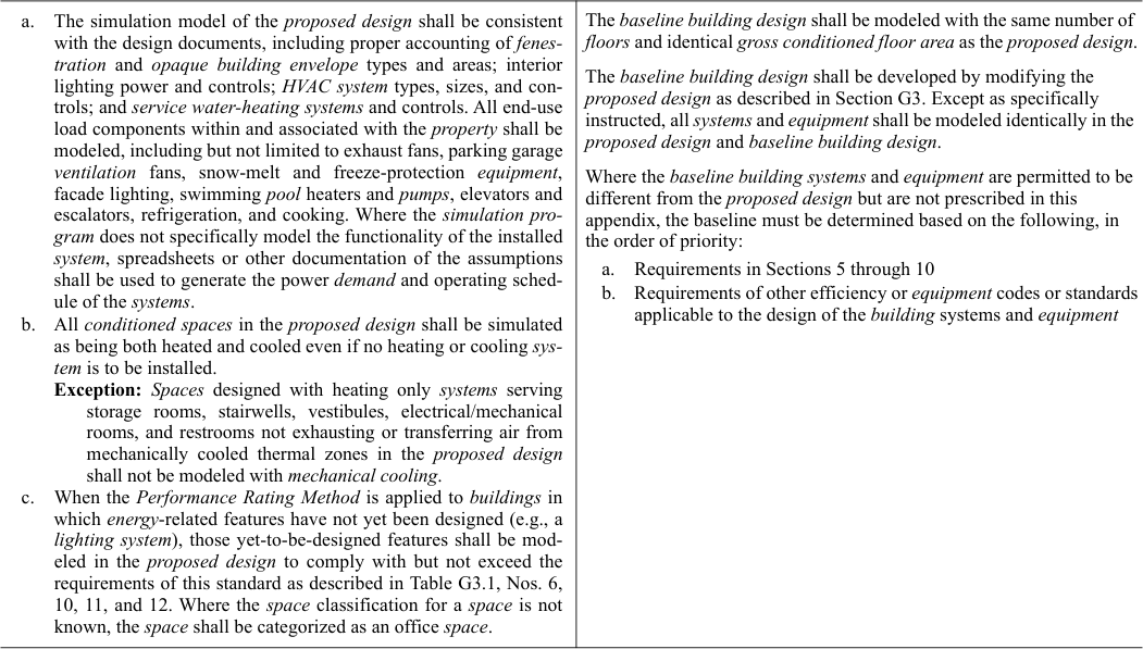
2. Additions and Alterations
3. Space Use Classification
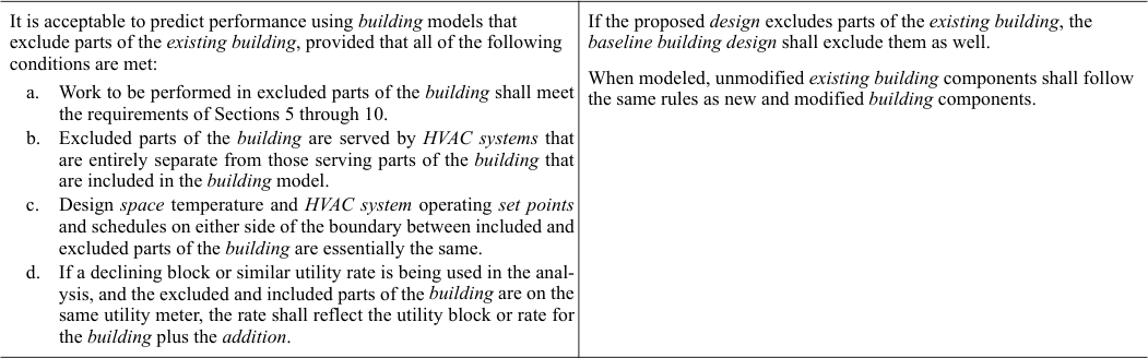
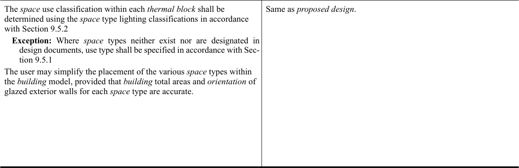
306 ANSI/ASHRAE/IES Standard 90.1-2022 (I-P)
PDF Page 309
Table G3.1 Modeling Requirements for Calculating Proposed Building Performance and Baseline Building Performance (Continued)
Proposed Building Performance Baseline Building Performance
4. Schedule
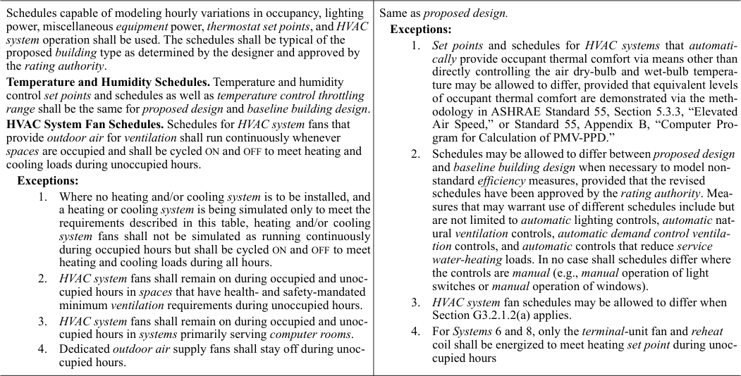
5. Building Envelope
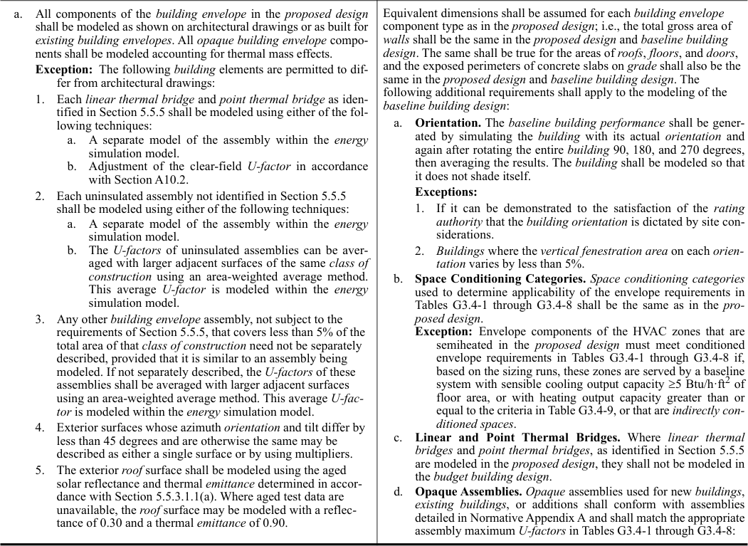
ANSI/ASHRAE/IES Standard 90.1-2022 (I-P) 307
PDF Page 310
Table G3.1 Modeling Requirements for Calculating Proposed Building Performance and Baseline Building Performance (Continued)
Proposed Building Performance Baseline Building Performance
5. Building Envelope (continued)
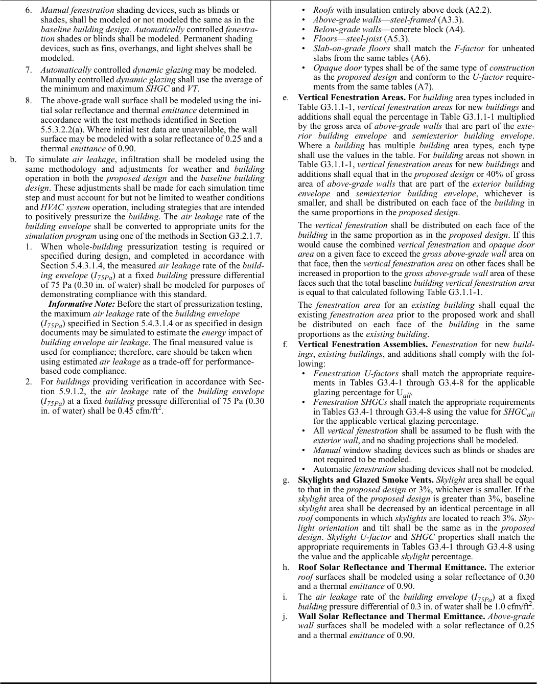
308 ANSI/ASHRAE/IES Standard 90.1-2022 (I-P)
PDF Page 311
Table G3.1 Modeling Requirements for Calculating Proposed Building Performance and Baseline Building Performance (Continued)
Proposed Building Performance Baseline Building Performance
6. Lighting
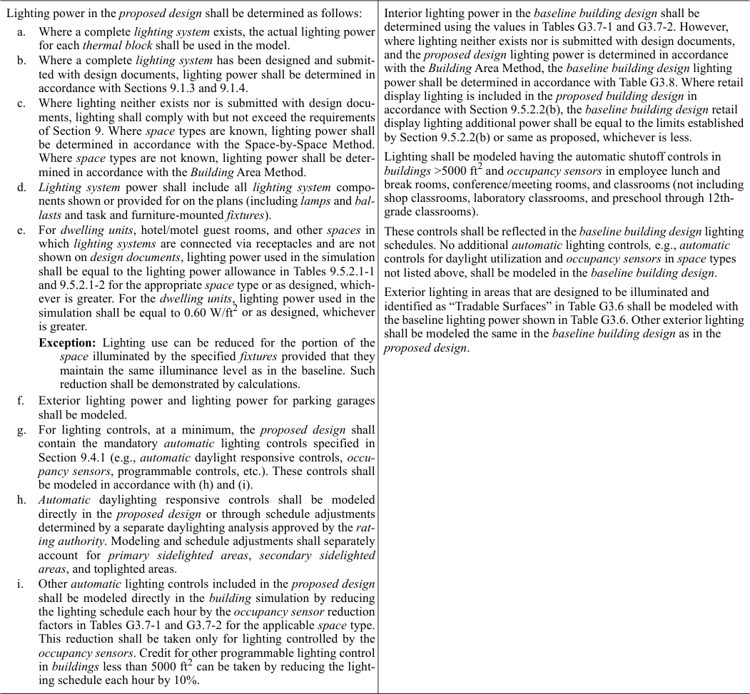
7. Thermal Blocks—HVAC Zones Designed
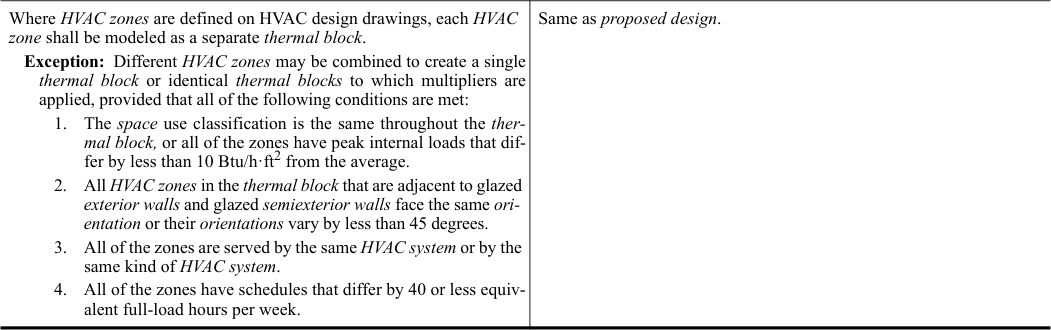
ANSI/ASHRAE/IES Standard 90.1-2022 (I-P) 309
PDF Page 312
Table G3.1 Modeling Requirements for Calculating Proposed Building Performance and Baseline Building Performance (Continued)
Proposed Building Performance Baseline Building Performance
8. Thermal Blocks—HVAC Zones Not Designed
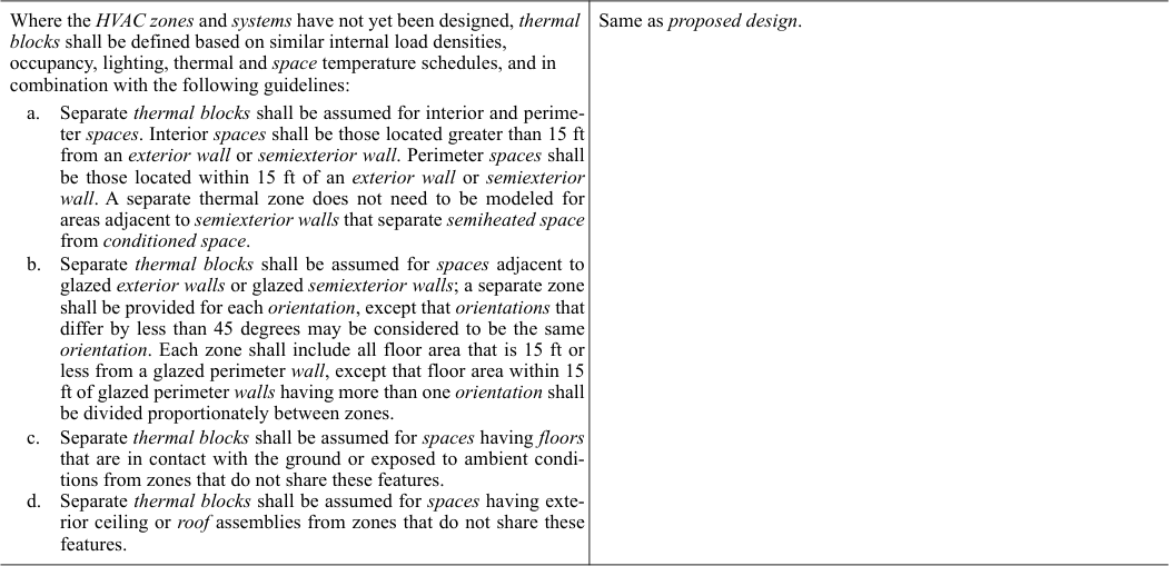
9. Thermal Blocks—Multifamily Residential Buildings
10. HVAC Systems

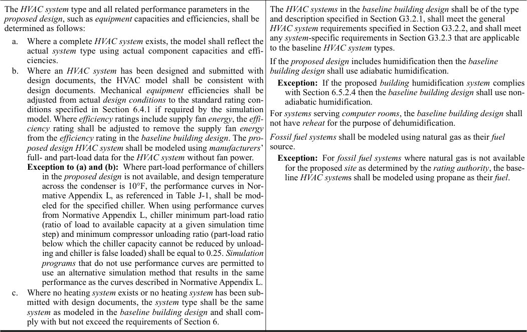
310 ANSI/ASHRAE/IES Standard 90.1-2022 (I-P)
PDF Page 313
Table G3.1 Modeling Requirements for Calculating Proposed Building Performance and Baseline Building Performance (Continued)
Proposed Building Performance Baseline Building Performance
10. HVAC Systems (continued)
11. Service Water-Heating Systems

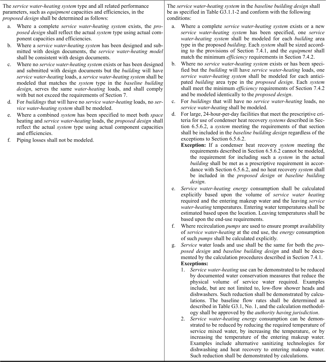
ANSI/ASHRAE/IES Standard 90.1-2022 (I-P) 311
PDF Page 314
Table G3.1 Modeling Requirements for Calculating Proposed Building Performance and Baseline Building Performance (Continued)
Proposed Building Performance Baseline Building Performance
11. Service Water-Heating Systems (continued)
12. Receptacle and Other Loads
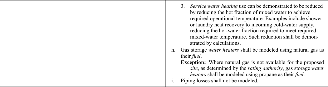
| Receptacle and process loads, such as those for office and other equipment, shall be estimated based on the building area type or space type category and shall be assumed to be identical in the proposed design and baseline building design, except as specifically approved by the rating authority only when quantifying performance that exceeds the requirements of Standard 90.1 but not when the Performance Rating Method is used as an alternative path for minimum standard compliance in accordance with Section 4.2.1.1. These loads shall always be included in simulations of the building. These loads shall be included when calculating the proposed building performance and the baseline building performance as required by Section G1.2.1. Exception: When receptacle controls installed in spaces where no t required by Section 8.4.2 are included in the proposed buildin g design, the hourly receptacle shall be reduced as follows: RPC = RC × 10% where RPC = receptacle power credit EPS = EPS × (1 – RPC) pro bas RC = percentage of all controlled receptacles EPS = baseline equipment power hourly schedule (fraction) bas EPS = proposed equipment power hourly schedule (fraction) pro a. Where power and other systems covered by Sections 8 and 10 hav e been designed and submitted with design documents, those sys- tems shall be determined in accordance with Sections 8 and 10. b. Where power and other systems covered by Sections 8 and 10 hav e not been submitted with design documents, those systems shal l comply with but not exceed the requirements of those sections. | Motors shall be modeled as having the efficiency ratings found in Table G3.9.1 Other systems covered by Section 10 and miscellaneous loads shall be modeled as identical to those in the proposed design, including schedules of operation and control of the equipment. Energy used for cooking equipment, receptacle loads, computers, medical or laboratory equipment, and manufacturing and industrial process equipment not specifically identified in the standard power and energy rating or capacity of the equipment shall be identical between the proposed building performance and the baseline building performance. Receptacle schedules shall be the same as the proposed design before the receptacle power credit is applied. Exception: When quantifying performance that exceeds the require- ments of Standard 90.1 (but not when using the Performance Rat- ing Method as an alternative path for minimum standar d compliance per Section 4.2.1.1) variations of the power require- ments, schedules, or control sequences of the equipment modeled in the baseline building design from those in the proposed design shal l be approved by the rating authority based on documentatio n described in Table G3.1(1), or that the equipment installed in th e proposed design represents a significant verifiable departure fro m documented current conventional practice. The burden of this docu- mentation is to demonstrate that accepted conventional practic e would result in baseline building equipment different from that installed in the proposed design. Occupancy and occupancy sched- ules shall not be changed. |
|---|---|
| 13. Modeling Limitations to the Simulation Program | |
| If the_simulation program_ cannot model a component or_system_ included in the_proposed design_ explicitly, substitute a thermodynamically similar component model that can approximate the expected performance of the component that cannot be modeled explicitly. | Same as_proposed design_. |
14. Exterior Conditions
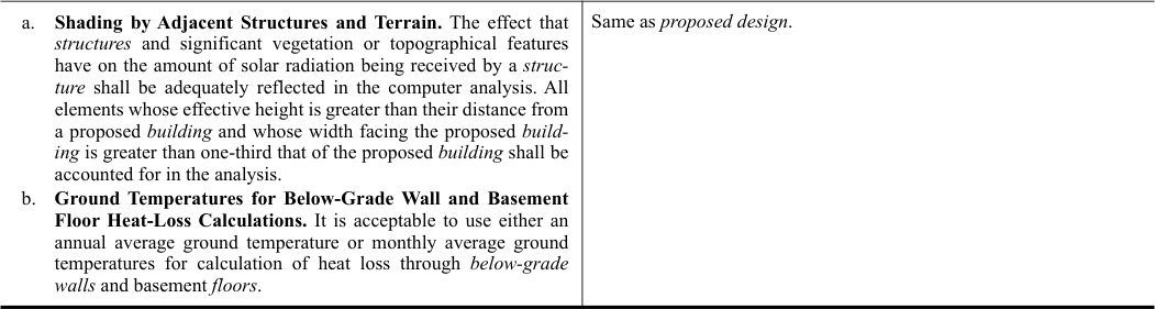
312 ANSI/ASHRAE/IES Standard 90.1-2022 (I-P)
PDF Page 315
Table G3.1 Modeling Requirements for Calculating Proposed Building Performance and Baseline Building Performance (Continued)
Proposed Building Performance Baseline Building Performance
14. Exterior Conditions (continued)
15. Distribution Transformers


16. Elevators
17. Refrigeration
18. On-Site Renewable Energy
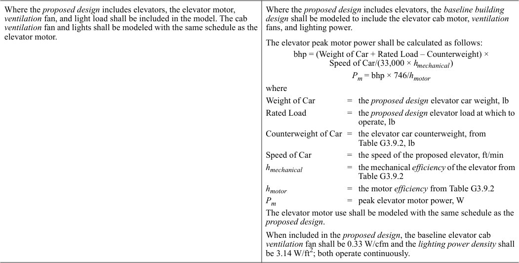


ANSI/ASHRAE/IES Standard 90.1-2022 (I-P) 313
PDF Page 316
d. The baseline HVAC system serving HVAC zones that include computer rooms shall be modeled in accor dance with one of the following:
- Baseline System 11 shall be used for such HVAC zones in buildings with a total computer room peak cooling load greater than 3,000,000 Btu/h.
- Baseline S ystem 11 shall be used for such HVAC zones in buildings where the baseline HVAC system type is 7 or 8 and the total computer room peak cooling load is greater than 600,000 Btu/h.
- Baseline System 3 or 4 shall be used for all other HVAC zones that include computer rooms based on climate zone. e. Residential associated HVAC zones shall use system type 3 or 4 based on climate zone.
G3.2.1.3 For baseline HVAC systems 1, 2, 3, 4, 9, 10, 11, 12, and 13, each HVAC zone or thermal block shall be modeled with its own HVAC system . For Systems 5, 6, 7, and 8, each floor shall be modeled with a separate HVAC system . Floors with identical HVAC zones or thermal blocks can be grouped for modeling purposes.
Exception to G3.2.1.3: Baseline system 5 or 7 serving laboratory spaces in accordance with Section
G3.2.1.2(b).
G3.2.1.4 Purchased Heat. For systems using purchased hot water or steam, the heating source shall be modeled as purchased hot water or steam in both the proposed design and baseline building design . Hotwater or steam costs shall be based on actual utility rates, and on- site boilers, electric heat, and furnaces shall not be modeled in the baseline building design .
G3.2.1.5 Purchased Chilled Water. For systems using purchased chilled water, the cooling source shall be modeled as purchased chilled water in both the proposed design and baseline building design . Purchased chilled-water costs shall be based on actual utility rates, and on- site chillers and direct expansion equipment shall not be modeled in the baseline building design .
G3.2.1.6 Baseline HVAC System Requirements for Systems Utilizing Purchased Chilled Water and/or Purchased Heat. If the proposed design uses purchased chilled water and/or purchased heat, the following modifications to the baseline HVAC system types in Table G3.1.1-4 shall be used.
G3.2.1.6.1 Purchased Heat Only. If the proposed design uses purchased heat, but does not use purchased chilled water, then Tables G3.1.1-3 and G3.1.1-4 shall be used to select the baseline HVAC system type, and purchased heat shall be substituted for the heating type in Table G3.1.1-4. The same heating source shall be used in the proposed design and baseline building design .
G3.2.1.6.2 Purchased Chilled Water Only. If the proposed design uses purchased chilled water but does not use purchased heat, then Tables G3.1.1-3 and G3.1.1-4 shall be used to select the baseline HVAC system type, with the modifications listed below:
a. Purchased chilled water shall be substituted for the cooling types in Table G3.1.1-4. b. System 1 and 2 shall be constant-volume fan-coil units with fossil fuel boilers . c. System 3 and 4 shall be constant-volume single-zone air handlers with fossil fuel furnaces. d. System 7 shall be used in place of System 5. e. System 8 shall be used in place of System 6.
G3.2.1.6.3 Purchased Chilled Water and Purchased Heat. If the proposed design uses purchased chilled water and purchased heat, then Tables G3.1.1-3 and G3.1.1-4 shall be used to select the baseline HVAC system type, with the following modifications:
a. Purchased heat and purchased chilled water shall be substituted for the heating types and cooling types in
Table G3.1.1-4. b. System 1 shall be constant-volume fan-coil units. c. System 3 shall be constant-volume single-zone air handlers. d. System 7 shall be used in place of System 5.
G3.2.1.6.4 On-Site Distribution Pumps. All on- site distribution pumps shall be modeled in both the proposed design and base building design .
G3.2.1.7 Modeling Building Envelope Air Leakage. The air leakage rate of the building envelope ( I75Pa ) at a pressure differential of 75 Pa (0.30 in. of water) shall be converted to appropriate units for the simulation program using one of the following formulas:
For methods describing air leakage as a function of floor area,
IFLR = 0.112 × I75Pa × S / AFLR
314 ANSI/ASHRAE/IES Standard 90.1-2022 (I-P)
PDF Page 317
For methods describing air leakage as a function of the area of above-grade walls that separate condi- tioned spaces and semiheated spaces from the exterior,
IAGW = 0.112 × I75Pa × S/AAGW When using the measured air leakage rate of the building envelope at a pressure differential of 0.3 in. of water for the proposed design, the air leakage rate shall be calculated as follows:
I75Pa = Q/S
where I75Pa = air leakage rate of the building envelope (cfm/ft [2] ) at a fixed building pressure differential of 75 Pa (0.30 in. of water) Q = volume of air in cfm flowing through the building envelope when subjected to a pressure differential of 75 Pa (0.30 in. of water), in accordance with ASTM E 779, ASTM E1827, or ASTM E3158 S = total area of the building envelope (ft [2] ), including the lowest floor, any below-grade walls or above-grade walls, and roof (including vertical fenestration and skylights ) IFLR = adjusted air leakage rate of the building envelope (cfm/ft [2] ) at a reference wind speed of 10 mph and relative to the gross floor area AFLR = gross floor area, ft [2]
IAGW = adjusted air leakage rate of the building envelope (cfm/ft [2] ) at a reference wind speed of 10 mph and relative to the area of the above-grade walls of the building envelope AAGW = total area of above-grade walls of the building envelope, ft [2]
Exceptions to G3.2.1.7: A multizone airflow model alternative method to modeling building envelope
air leakage may be used, provided the following criteria are met:
- Where the calculations are made independently of the energy simulation program, the proposed method must comply with Section G2.5.
- The method for converting the air leakage rate of the building envelope at 0.3 in. of water, or 1.57 psf, to the appropriate units for the simulation program is fully documented and submitted to the rating authority for approval.
G3.2.2 General Baseline HVAC System Requirements. HVAC systems in the baseline building design shall conform with the general provisions in this section.
G3.2.2.1 Equipment Efficiencies. All HVAC equipment in the baseline building design shall be modeled at the minimum efficiency levels, both part load and full load, in accordance with Tables G3.5.1 through G3.5.6. Where multiple HVAC zones are combined into a single thermal block in accordance with Table G3.1, the efficiencies (for baseline HVAC System Types 3, 4, 9, and 10) taken from Tables G3.5.1, G3.5.2, and G3.5.5 shall be based on the equipment capacity of the thermal block divided by the number of HVAC zones . HVAC System Types 5 or 6 efficiencies taken from Table G3.5.1 shall be based on the cooling equip- ment capacity of a single story when grouping identical stories in accordance with Section G3.2.1.1(a)(4). Fan energy shall be modeled separately according to Section G3.2.1.7.
COPnfcooling and COPnfheating are the packaged HVAC equipment cooling and heating energy efficiency, respectively, to be used in the baseline building design, which excludes supply fan power.
The sets of performance curves specified in Table J-2 should be used to represent part-load performance of chillers in the baseline building design. When using performance curves from Normative Appendix J, chiller minimum part-load ratio (ratio of load to available capacity at a given simulation time step) and minimum compressor unloading ratio (part-load ratio below which the chiller capacity cannot be reduced by unloading and chiller is false loaded) shall be equal to 0.25. Simulation programs that do not use performance curves are permitted to use an alternative simulation method that results in the same performance as the curves described in Normative Appendix J.
G3.2.2.2 Equipment Capacities. System coil capacities for the baseline building design shall be based on sizing runs for each orientation in accordance with Table G3.1, No. 5[a] and Section G3.2.2.2.1, and shall be oversized by 15% for cooling and 25% for heating. The ratio between the capacities used in the annual simulations and the capacities determined by the sizing runs shall be 1.15 for cooling and 1.25 for heating. Plant capacities shall be based on coincident loads.
G3.2.2.2.1 Sizing Runs. Weather conditions used in sizing runs to determine baseline equipment capacities shall be based on design days developed using heating design temperatures, cooling design tem- perature, and cooling design wet-bulb temperature . For cooling sizing runs, schedules for internal loads,
ANSI/ASHRAE/IES Standard 90.1-2022 (I-P) 315
PDF Page 318
including those used for infiltration, occupants, lighting, gas and electricity using equipment, shall be equal to the highest hourly value used in the annual simulation runs and applied to the entire design day. For heating sizing runs, schedules for internal loads, including those used for occupants, lighting, gas and electricity using equipment, shall be equal to the lowest hourly value used in the annual simulation runs, and schedules for infiltration shall be equal to the highest hourly value used in the annual simulation runs and applied to the entire design day.
Exception to G3.2.2.2.1: For cooling sizing runs in residential dwelling units, the infiltration, occu pants, lighting, gas and electricity using equipment hourly schedule shall be the same as the most used hourly weekday schedule from the annual simulation.
G3.2.2.3 Unmet Loads. Unmet load hours for the proposed design or baseline building design shall not exceed 300 (of the 8760 hours simulated). Alternatively, unmet load hours exceeding these limits shall be permitted to be accepted upon approval of the rating authority, provided that sufficient justification is given indicating that the accuracy of the simulation is not significantly compromised by these unmet loads.
G3.2.2.4 Ventilation. Minimum ventilation system outdoor air intake flow shall be the same for the proposed design and baseline building design .
Exceptions to G3.2.2.4:
- When modeling demand control ventilation in the proposed design in systems with outdoor air capacity less than or equal to 3000 cfm serving areas with an average design capacity of 100 people per 1000 ft [2] or less.
- When designing systems in accordance with Standard 62.1, Section 6.2, “ Ventilation Rate Procedure,” reduced ventilation airflow rates may be calculated for each HVAC zone in the proposed design with a zone air distribution effectiveness ( Ez ) > 1.0 as defined by Standard 62.1, Table 6-2. Baseline ventilation airflow rates in those zones shall be calculated using the proposed design Ventilation Rate Procedure calculation with the following change only. Zone air distribution effectiveness shall be changed to ( Ez ) = 1.0 in each zone having a zone air distribution effectiveness ( Ez ) > 1.0. Proposed design and baseline building design Ventilation Rate Procedure calculations, as described in Standard 62.1, shall be submitted to the rating authority to claim credit for this exception.
- Where the minimum outdoor air intake flow in the proposed design is provided in excess of the amount required by the building code or the rating authority, the baseline building design shall be modeled to reflect the greater of that required by either the rating authority or the building code and will be less than the proposed design .
- For baseline systems serving only laboratory spaces that are prohibited from recirculating return air by code or accreditation standards, the baseline system shall be modeled as 100% outdoor air .
G3.2.2.5 Economizers. Air economizers shall not be included in baseline HVAC Systems 1, 2, 9, and 10. Integrated air economizer control shall be included in baseline HVAC Systems 3 through 8, and 11, 12, and 13 based on climate as specified in Table G3.2.2.5. Exceptions to G3.2.2.5: Economizers shall not be included for systems meeting one or more of the
exceptions listed below.
- Systems that include gas-phase air cleaning to meet the requirements of Standard 62.1, Section 6.1.2. This exception shall be used only if the system in the proposed design does not match the building design.
- Where the use of outdoor air for cooling will affect supermarket open refrigerated casework sys- tems . This exception shall only be used if the system in the proposed design does not use an economizer. If the exception is used, an economizer shall not be included in the baseline building design .
- Systems that serve computer rooms complying with Section G3.2.2.5.1.
G3.2.2.5.1 Computer Room Economizers. Systems that serve computer rooms that are HVAC System 3 or 4 shall not have an economizer. Systems that serve computer rooms that are HVAC System 11 shall include an integrated fluid economizer meeting the requirements of Section 6.5.1.2 in the baseline building design .
G3.2.2.6 Economizer High-Limit Shutoff. The high-limit shutoff shall be a dry-bulb fixed switch with set-point temperatures in accordance with the values in Table G3.2.2.6.
G3.2.2.7 Design Airflow Rates
G3.2.2.7.1 Baseline All System Types Except System Types 9 and 10. System design supply airflow rates for the baseline building design shall be based on a supply-air-to-room temperature set-point difference of 20°F or the minimum outdoor airflow rate, or the airflow rate required to comply with applicable codes or
316 ANSI/ASHRAE/IES Standard 90.1-2022 (I-P)
PDF Page 319
accreditation standards, whichever is greater. For systems with multiple zone thermostat set points, use the design set point that will result in the lowest supply air cooling set point or highest supply air heating set point . If return or relief fans are specified in the proposed design, the baseline building design shall also be modeled with fans serving the same functions and sized for the baseline system supply fan air quantity less the minimum outdoor air, or 90% of the supply fan air quantity, whichever is larger.
Exceptions to G3.2.2.7.1:
- For systems serving laboratory spaces, airflow rate shall be based on a supply-air-to-room temperature set-point difference of 17°F or the required ventilation air or makeup air, whichever is greater.
- If the proposed design HVAC system airflow rate based on latent loads is greater than the design airflow rate based on sensible loads, then the same supply-air-to-room-air humidity ratio difference (gr/lb) used to calculate the proposed design airflow shall be used to calculate design airflow rates for the baseline building design .
G3.2.2.7.2 Baseline System Types 9 and 10. System design supply airflow rates for the baseline building design shall be based on the temperature difference between a supply air temperature set point of 105°F and the design space -heating temperature set point, the minimum outdoor airflow rate, or the airflow rate required to comply with applicable codes or accreditation standards, whichever is greater. If the pro- posed design includes a fan or fans sized and controlled to provide non- mechanical cooling, the baseline building design shall include a separate fan to provide non- mechanical cooling, sized and controlled the same as the proposed design .
G3.2.2.8 System Fan Power. System fan electrical power for supply, return, exhaust, and relief (excluding power to fan-powered VAV boxes) shall be calculated using the following formulas:
For Systems 1 and 2,
Pfan = CFM s × 0.3
For Systems 3 through 8, and 11, 12, and 13,
Pfan = bhp × 746/fan motor efficiency
For Systems 9 and 10 (supply fan),
Pfan = CFM s × 0.3
For Systems 9 and 10 (non- mechanical cooling fan if required by Section G3.2.2.7.2),
Pfan = CFM nmc × 0.054
where Pfan = electric power to fan motor, W bhp = brake horsepower of baseline fan motor fromTable G3.2.2.8 fan motor efficiency = the efficiency for the next motor size greater than the bhp from Table G3.2.2.8 CFM s = the baseline system maximum design supply fan airflow rate, cfm CFM nmc = the baseline non- mechanical cooling fan airflow, cfm G3.2.2.8.1 The calculated system fan power shall be distributed to supply, return, exhaust, and relief fans in the same proportion as the proposed design .
G3.2.2.9 Exhaust Air Energy Recovery. Individual fan systems that have both a design supply air capacity of 5000 cfm or greater and have a minimum design outdoor air supply of 70% or greater shall have an energy recovery system with at least 50% enthalpy recovery ratio . Fifty percent enthalpy recovery ratio shall mean a change in the enthalpy of the outdoor air supply equal to 50% of the difference between the outdoor air and return air at design conditions . Provision shall be made to bypass or control the heat recovery system to permit air economizer operation, where applicable.
Exceptions to G3.2.2.9: If any of these exceptions apply, exhaust air energy recovery shall not be
included in the baseline building design :
- Systems serving spaces that are not cooled and that are heated to less than 60°F.
- Systems exhausting toxic, flammable, or corrosive fumes or paint or dust. This exception shall only be used if exhaust air energy recovery is not used in the proposed design .
- Commercial kitchen hoods (grease) classified as Type 1 by NFPA 96. This exception shall only be used if exhaust air energy recovery is not used in the proposed design .
- Heating systems in Climate Zones 0 through 3.
ANSI/ASHRAE/IES Standard 90.1-2022 (I-P) 317
PDF Page 320
- Cooling systems in Climate Zones 3C, 4C, 5B, 5C, 6B, 7, and 8.
- Where the largest exhaust source is less than 75% of the design outdoor airflow . This exception shall only be used if exhaust air energy recovery is not used in the proposed design .
- Systems requiring dehumidification that employ energy recovery in series with the cooling coil. This exception shall only be used if exhaust air energy recovery and series-style energy recovery coils are not used in the proposed design .
- Systems serving laboratory HVAC zones with a total laboratory exhaust volume greater than 15,000 cfm.
G3.2.3 System-Specific Baseline HVAC System Requirements. Baseline HVAC systems shall conform with provisions in this section, where applicable, to the specified baseline system types, as indicated in section headings.
G3.2.3.1 Heat Pumps (Systems 2 and 4). Electric air source heat pumps shall be modeled with electric auxiliary heat and an outdoor air thermostat . The systems shall be controlled to energize auxiliary heat only when the outdoor air temperature is less than 40°F. The air source heat pump shall be modeled to continue to operate while auxiliary heat is energized.
G3.2.3.2 Type and Number of Boilers (Systems 1, 5, 7, 11, and 12). The boiler plant shall be natural draft, except as noted in Section G3.2.1.4. The baseline building design boiler plant shall be modeled as having a single boiler if the baseline building design plant serves a gross conditioned floor area of 15,000 ft [2] or less, and as having two equally sized boilers for plants serving more than 15,000 ft [2] . Boilers shall be staged as required by the load.
G3.2.3.3 Hot-Water Supply Temperature (Systems 1, 5, 7, 11, and 12). Hot-water design supply temperature shall be modeled as 180°F and design return temperature as 130°F.
G3.2.3.4 Hot-Water Supply Temperature Reset (Systems 1, 5, 7, 11, and 12). Hot-water supply temperature shall be reset based on outdoor dry-bulb temperature using the following schedule: 180°F at 20°F and below, 150°F at 50°F and above, and ramped linearly between 180°F and 150°F at temperatures between 20°F and 50°F.
Exception to G3.2.3.4: Systems served by purchased heat.
G3.2.3.5 Hot-Water Pumps (Systems 1, 5, 7, 11, and 12). The baseline building design hot-water pump power shall be 19 W/gpm. The pumping system shall be modeled as primary-only with continuous variable flow and a minimum of 25% of the design flow rate. Hot-water pumps shall only be enabled when a load exists on the associated hot-water loop . Hot-water systems serving 120,000 ft [2] or more shall be modeled with variable-speed drives, and systems serving less than 120,000 ft [2] shall be modeled as riding the pump curve.
Exception to G3.2.3.5: The pump power for systems using purchased heat shall be 14 W/gpm.
G3.2.3.6 Piping Losses (Systems 1, 5, 7, 8, 11, 12, and 13). Piping losses shall not be modeled in either the proposed design or baseline building design for hot-water, chilled-water, or steam piping .
G3.2.3.7 Type and Number of Chillers (Systems 7, 8, 11, 12, and 13). Electric chillers shall be used in the baseline building design regardless of the cooling energy source, e.g. direct-fired absorption or absorption from purchased steam. The baseline building design ’s chiller plant shall be modeled with chillers having the number and type as indicated in Table G3.2.3.7 based on the peak coincident cooling load of baseline HVAC systems using chilled water.
Exception to G3.2.3.7: Systems using purchased chilled water shall be modeled in accordance with
Section G3.2.1.6.
G3.2.3.8 Chilled-Water Design Supply Temperature (Systems 7, 8, 11, 12, and 13). Chilled-water design supply temperature shall be modeled at 44°F and return water temperature at 56°F.
G3.2.3.9 Chilled-Water Supply Temperature Reset (Systems 7, 8, 11, 12, and 13). Chilled-water supply temperature shall be reset based on outdoor dry-bulb temperature using the following schedule: 44°F at 80°F and above, 54°F at 60°F and below, and ramped linearly between 44°F and 54°F at temperatures between 80°F and 60°F.
Exception to G3.2.3.9:
- If the baseline chilled-water system serves a computer room HVAC system, the supply chilledwater temperature shall be reset higher based on the HVAC system requiring the most cooling; i.e., the chilled-water set point is reset higher until one cooling-coil valve is nearly wide open. The maximum reset chilled-water supply temperature shall be 54°F.
- Systems served by purchased chilled water.
318 ANSI/ASHRAE/IES Standard 90.1-2022 (I-P)
PDF Page 321
G3.2.3.10 Chilled-Water Pumps (Systems 7, 8, 11, 12, and 13). Chilled-water systems shall be modeled as primary/secondary systems with constant-flow primary loop and variable-flow secondary loop. For systems with cooling capacity of 300 tons or more, the secondary pump shall be modeled with variablespeed drives and a minimum flow of 25% of the design flow rate. Chilled-water pumps shall only be enabled when a load exists on the associated chilled-water loop . For systems with less than 300 tons cooling capacity, the secondary pump shall be modeled as riding the pump curve. The baseline building constant-volume primary pump power shall be modeled as 9 W/gpm, and the variable-flow secondary pump power shall be modeled as 13 W/gpm at design conditions . For computer room systems using System 11 with an integrated fluid economizer, the baseline building design primary chilled-water pump power shall be increased by 3 W/ gpm for flow associated with the fluid economizer .
Exception to G3.2.3.10: For systems using purchased chilled water, the building distribution pump shall
be modeled with variable-speed drive, a minimum flow of 25% of the design flow rate, and a pump power of 16 W/gpm.
G3.2.3.11 Heat Rejection (Systems 7, 8, 11, 12, and 13). The heat-rejection device shall be an axialfan open-circuit cooling tower with variable-speed fan control and shall have an efficiency of 38.2 gpm/hp at the conditions specified in Table 6.8.1-7. Condenser-water design supply temperature shall be calculated using the cooling tower approach to the 0.4% evaporation design wet-bulb temperature as generated by the formula below, with a design temperature rise of 10°F:
Approach 10°F Range = 25.72 – (0.24 × WB)
where WB is the 0.4% evaporation design wet-bulb temperature (°F); valid for wet bulbs from 55°F to 90°F.
The tower shall be controlled to maintain a leaving water temperature, where weather permits, per Table G3.2.3.11, floating up to the design leaving water temperature for the cooling tower. The baseline building design condenser-water pump power shall be 19 W/gpm and modeled as constant volume. For computer room systems using System 11 with an integrated fluid economizer, the baseline building design condenserwater- pump power shall be increased by 3 W/gpm for flow associated with the fluid economizer . Each chiller shall be modeled with separate condenser-water and chilled-water pumps interlocked to operate with the associated chiller.
G3.2.3.12 Supply Air Temperature Reset (Systems 5 through 8 and 11). The air temperature for cooling shall be reset higher by 5°F under the minimum cooling load conditions.
G3.2.3.13 VAV Minimum Flow Set Points (Systems 5 and 7). Minimum volume set points for VAV reheat boxes shall be 30%of zone peak airflow, the minimum outdoor airflow rate, or the airflow rate required to comply with applicable codes or accreditation standards, whichever is larger.
Exception to G3.2.3.13: Systems serving laboratory spaces shall reduce the exhaust and makeup air
volume during unoccupied periods to the largest of 50% of zone peak airflow, the minimum outdoor airflow rate, or the airflow rate required to comply with applicable codes or accreditation standards.
G3.2.3.14 Fan Power and Control (Systems 6 and 8). Fans in parallel VAV fan-powered boxes shall run as the first stage of heating before the reheat coil is energized. Fans in parallel VAV fan-powered boxes shall be sized for 50% of the peak design primary air (from the VAV air-handling unit) flow rate and shall be modeled with 0.35 W/cfm fan power. Minimum volume set points for fan-powered boxes shall be equal to 30% of peak design primary airflow rate or the rate required to meet the minimum outdoor air ventilation requirement, whichever is larger. The supply air temperature set point shall be constant at the design condition .
G3.2.3.15 VAV Fan Part-Load Performance (Systems 5 through 8 and 11). VAV system supply fans shall have variable-speed drives, and their part-load performance characteristics shall be modeled using either Method 1 or Method 2 specified in Table G3.2.3.15.
G3.2.3.16 Computer Room Equipment Schedules. Computer room equipment schedules shall be modeled as a constant fraction of the peak design load per the following monthly schedule:
Month 1, 5, 9—25% Month 2, 6, 10—50% Month 3, 7, 11—75% Month 4, 8, 12—100%
G3.2.3.17 System 11 Supply Air Temperature and Fan Control. Minimum volume set point shall be 50% of the maximum design airflow rate, the minimum ventilation outdoor airflow rate, or the airflow rate required to comply with applicable codes or accreditation standards, whichever is larger.
Fan volume shall be reset from 100% airflow at 100% cooling load to minimum airflow at 50% cooling load. Supply air temperature set point shall be reset from minimum supply air temperature at 50% cooling
ANSI/ASHRAE/IES Standard 90.1-2022 (I-P) 319
PDF Page 322
load and above to space temperature at 0% cooling load. In heating mode supply air temperature shall be modulated to maintain space temperature, and fan volume shall be fixed at the minimum airflow.
G3.2.3.18 Dehumidification (Systems 3 through 8 and 11, 12, and 13). If the proposed design HVAC systems have humidistatic controls, then the baseline building design shall use mechanical cooling for dehumidification and shall have reheat available to avoid overcooling. When the baseline building design HVAC system does not comply with any of the exceptions in Section 6.5.2.3, then only 25% of the system reheat energy shall be included in the baseline building performance . The reheat type shall be the same as the sys- tem heating type.
G3.2.3.19 Preheat Coils (Systems 5 through 8). The baseline system shall be modeled with a preheat coil controlled to a fixed set point 20°F less than the maximum design heating temperature set point of the HVAC zones served by the system.
G3.3 Performance Calculations for Other Alterations
G3.3.1 Proposed Building Performance. The simulation model for calculating the proposed building performance shall be developed in accordance with the requirements in Table G3.1, Proposed Building Performance column and the following additional requirements:
a. New and retrofitted systems and equipment shall be consistent with design documents. b. Systems and equipment excluded from the scope of retrofit shall reflect the existing conditions.
G3.3.2 Baseline Building Performance
G3.3.2.1 General Approach. System and equipment included in the scope of retrofit shall be modeled at efficiency levels meeting the mandatory and prescriptive requirements in Sections 5 through 10 and as described in this section. All other baseline systems and equipment shall be modeled the same as in the pro- posed design.
G3.3.2.2 Schedules. Schedules modeled in the baseline design are allowed to differ from the proposed design following Table G3.1(4), Baseline Building Performance column, Exceptions 1 through 3.
G3.3.2.3 Opaque Assemblies. Opaque assemblies shall be modeled with U-factors meeting the requirements in Section 5.1.3.
G3.3.2.4 Fenestration. Fenestration U-factor, SHGC, and VT shall be modeled as meeting the requirements in Section 5.1.3.
The fenestration area for an existing building shall equal the existing fenestration area prior to the proposed work and shall be distributed on each face of the building in the same proportions as the existing building.
G3.3.2.5 Air Leakage. When Section 5.4.3.1.3 applies, the air leakage rate of the building envelope ( I75Pa ) shall be equal to 0.35 cfm/ft [2] of building envelope area at a pressure differential of 75 Pa (0.30 in. of water). The air leakage rate shall be converted to appropriate units for the simulation software using the same method as the proposed design .
G3.3.2.6 Interior Lighting. Interior lighting power density shall be modeled as meeting Section 9.1.1.3.1 using applicable allowances in Section 9.5.2.1. Lighting controls shall be modeled as meeting Section 9.1.1.3.1.
G3.3.2.7 Exterior Lighting. Tradable exterior lighting shall be modeled as meeting Section 9.1.1.3.2.
G3.3.2.8 HVAC Systems
a. Baseline HVAC system types shall be the same as the proposed design .
Exception to G3.3.2.8(a): If the proposed design includes variable refrigerant flow heat pumps or sin-
gle-zone systems with electric resistance heat, then air source heat pumps shall be used in the base- line design . b. Baseline systems shall meet the requirements in Section 6.1.3. Chillers shall meet the efficiency require ments in Table 6.8.1-3 using Path A or Path B, the same as the proposed design . If the proposed design meets both Path A and Path B requirements, Path A shall be used. c. Where the efficiency rating includes supply fan energy, calculate the minimum COPnfcooling and COPnf-
heating [ in accordance with Section 12.5.2(c).] d. Fan system efficiency (bhp per cfm of supply air, including the effect of belt losses but excluding motor
and motor drive losses) shall be the same as the proposed design or up to the limit prescribed in Section 6.5.3.1, whichever is smaller. If this limit is reached, each fan shall be proportionally reduced in brake horsepower until the limit is met. Fan electrical power shall then be determined by adjusting the calcu
320 ANSI/ASHRAE/IES Standard 90.1-2022 (I-P)
PDF Page 323
lated fan hp by the minimum motor efficiency prescribed by Section 10.4.1 for the appropriate motor size for each fan. Exception to G3.3.2.8(d): When a proposed design includes energy recovery but it is not required in
the baseline building design per Section 6.5.6, the fan power of the baseline system shall be equal to either the proposed design system or the fan power limit in Section 6.5.3.1 calculated without fan power credit for energy recovery, whichever is less. e. The equipment capacities for the baseline design shall be sized proportionally to the capacities in the
proposed design based on sizing runs—i.e., the ratio between the capacities used in the annual simulations and the capacities determined by the sizing runs shall be the same for both the proposed design and budget building design .
G3.3.2.9 Service Water Heating Systems. Service water heating systems shall be modeled as meeting Section 7.1.4. Service water heating energy use can be documented to be reduced as allowed in Table G3.1(11) Baseline Building Performance column exceptions to (g).
ANSI/ASHRAE/IES Standard 90.1-2022 (I-P) 321
PDF Page 324
Table G3.1.1-1 Baseline Building Vertical Fenestration
| Building Area Typesa | Baseline Building Vertical Fenestration Area as a Percentage of Gross Above-Grade-Wall Area |
|---|---|
| Grocery store | 7% |
| Healthcare (outpatient) | 21% |
| Hospital | 27% |
| Hotel/motel (≤75 rooms) | 24% |
| Hotel/motel (>75 rooms) | 34% |
| Office (≤5000 ft2) | 19% |
| Office (5000 to 50,000 ft2) | 31% |
| Office (>50,000 ft2) | 40% |
| Restaurant (quick service) | 34% |
| Restaurant (full service) | 24% |
| Retail (stand alone) | 11% |
| Retail (strip mall) | 20% |
| School (primary) | 22% |
| School (secondary and university) | 22% |
| Warehouse (nonrefrigerated) | 6% |
Table G3.1.1-2 Baseline Service Water-Heating System
| Building Area Type | Baseline Heating Method |
|---|---|
| Performing arts theater | Gas storage_water heater_ |
| Police station | Electric resistance storage_water heater_ |
| Post office | Electric resistance storage_water heater_ |
| Religious_facility_ | Electric resistance storage_water heater_ |
| Retail | Electric resistance storage_water heater_ |
| School/university | Gas storage_water heater_ |
| Sports arena | Gas storage_water heater_ |
| Town hall | Electric resistance storage_water heater_ |
| Transportation | Electric resistance storage_water heater_ |
| Warehouse | Electric resistance storage_water heater_ |
| Workshop | Electric resistance storage_water heater_ |
| All others | Gas storage_water heater_ |
| Building Area Type | Baseline Heating Method |
|---|---|
| Automotive facility | Gas storage_water heater_ |
| Convenience store | Electric resistance water heater |
| Convention center | Electric resistance storage_water heater_ |
| Courthouse | Electric resistance storage_water heater_ |
| Dining: Bar lounge/leisure | Gas storage_water heater_ |
| Dining: Cafeteria/fast food | Gas storage_water heater_ |
| Dining: Family | Gas storage_water heater_ |
| Dormitory | Gas storage_water heater_ |
| Exercise center | Gas storage_water heater_ |
| Fire station | Gas storage_water heater_ |
| Grocery store | Gas storage_water heater_ |
| Gymnasium | Gas storage_water heater_ |
| Health care clinic | Electric resistance storage_water heater_ |
| Hospital and outpatient surgery center | Gas storage_water heater_ |
| Hotel | Gas storage_water heater_ |
| Library | Electric resistance storage_water heater_ |
| Manufacturing facility | Gas storage_water heater_ |
| Motel | Gas storage_water heater_ |
| Motion picture theater | Electric resistance storage_water heater_ |
| Multifamily | Gas storage_water heater_ |
| Museum | Electric resistance storage_water heater_ |
| Office | Electric resistance storage_water heater_ |
| Parking garage | Electric resistance storage_water heater_ |
| Penitentiary | Gas storage_water heater_ |
322 ANSI/ASHRAE/IES Standard 90.1-2022 (I-P)
PDF Page 325
| Table G3.1.1-3 Baseline HVAC System Types | Col2 | Col3 |
|---|---|---|
| Building Area Types a, Number of Stories b, and Combined Floor Area c | Climate Zones 3B, 3C, and 4 to 8 | Climate Zones 0 to 3A |
| Residential | System 1—PTAC | System 2—PTHP |
| Public assembly area smaller than 120,000 ft2 | System 3—PSZ-AC | System 4—PSZ-HP |
| Public assembly area equal to or larger than120,000 ft2 | System 12—SZ-CV-HW | System 13—SZ-CV-ER |
| Heated-only storage | System 9—Heating and_ventilation_ | System 10—Heating and_ventilation_ |
| Retail in a_building_ that is 1 or 2_stories_ | System 3—PSZ-AC | System 4—PSZ-HP |
| Hospital that is either • larger than 150,000 ft2 or • in a_building_ greater than 5_stories_. | System 7—VAV with_reheat_ | System 7—VAV with_reheat_ |
| Hospital—all other | System 5—Packaged_VAV_ with reheat | System 5—Packaged_VAV_ with_reheat_ |
| Other_Nonresidential_ area that is both • smaller than 25,000 ft2 and • in a_building_ 3_stories_ or fewer. | System 3—PSZ-AC | System 4—PSZ-HP |
| Other_Nonresidential_ area that is both • smaller than 25,000 ft2 and • in a_building_ with 4 or 5_stories_. | System 5—Packaged_VAV_ with_reheat_ | System 6—Packaged_VAV_ with PFP boxes |
| Other_nonresidential_ area that is both • 25,000 ft2 to 150,000 ft2 and • in a_building_ that is 5_stories_ or fewer. | System 5—Packaged_VAV_ with_reheat_ | System 6—Packaged_VAV_ with PFP boxes |
| Other_Nonresidential_ area that is either • larger than 150,000 ft2 or • in a_building_ greater than 5_stories_. | System 7—VAV with_reheat_ | System 8—VAV with PFP boxes |
a. Building area type determined in accordance with Section G3.2.1.1. b. The total number of stories in a building, including above-grade and below-grade stories but not including stories solely devoted to parking. c. Combined gross conditioned floor area and semiheated floor area, of the building area type, based on the requirements of Section G3.2.1.1.
Table G3.1.1-4 Baseline System Descriptions
| System No. | System Type | Fan Control | Cooling Type a | Heating Type a |
|---|---|---|---|---|
| 1. PTAC | Packaged terminal air conditioner | Constant volume | Direct expansion | Hot-water_fossil fuel_ boiler |
| 2. PTHP | Packaged terminal heat pump | Constant volume | Direct expansion | Electric heat pump |
| 3. PSZ-AC | Packaged rooftop air conditioner | Constant volume | Direct expansion | Fossil fuel furnace |
| 4. PSZ-HP | Packaged rooftop heat pump | Constant volume | Direct expansion | Electric heat pump |
| 5. Packaged_VAV_ with reheat | Packaged rooftop_VAV_ with_reheat_ | VAV | Direct expansion | Hot-water_fossil fuel_ boiler |
| 6. Packaged_VAV_ with PFP boxes | Packaged rooftop_VAV_ with parallel fan power boxes and_reheat_ | VAV | Direct expansion | Electric resistance |
| 7. VAV with_reheat_ | VAV with_reheat_ | VAV | Chilled water | Hot-water_fossil fuel_ boiler |
| 8. VAV with PFP boxes | VAV with parallel fan-powered boxes and_reheat_ | VAV | Chilled water | Electric resistance |
| 9. Heating and_ventilation_ | Warm air furnace, gas fired | Constant volume | None | Fossil fuel furnace |
| 10.Heating and_ventilation_ | Warm air furnace, electric | Constant volume | None | Electric resistance |
| 11.SZ–VAV | Single-zone_VAV_ | VAV | Chilled water | See note (b). |
| 12.SZ-CV-HW | Single-zone system | Constant volume | Chilled water | Hot-water_fossil fuel_ boiler |
| 13.SZ-CV-ER | Single-zone system | Constant volume | Chilled water | Electric resistance |
a. For purchased chilled water and purchased heat, see Section G3.2.1.3. b. For Climate Zones 0 through 3A, the heating type shall be electric resistance . For all other climate zones the heating type shall be hot-water fossil- fuel boiler .
ANSI/ASHRAE/IES Standard 90.1-2022 (I-P) 323
PDF Page 326
Table G3.2.2.5 Climate Conditions under which Economizers are Included for Comfort Cooling for Baseline Systems 3 through 8 and 11, 12, and 13
Note: NR means that there is no conditioned building floor area for which economizers are included for the type of zone and climate.
Table G3.2.2.6 Economizer High-Limit Shutoff Temperature
Table G3.2.2.8 Baseline Fan Brake Horsepower
Baseline Fan Motor Brake Horsepower
Notes:
- Where A is calculated according to Section 6.5.3.1.1 using the pressure-drop adjustment from the proposed design and the design flow rate of the baseline building system .
- Do not include pressure-drop adjustments for evaporative coolers or heat recovery devices that are not required in the baseline building system by Section G3.2.2.9.
Table G3.2.3.7 Type and Number of Chillers
| Peak Coincident Cooling Load of Baseline HVAC Systems Using Chilled Water | Number and Type of Chillers |
|---|---|
| 300 tons | 1 liquid-cooled screw chiller |
| >300 tons, <600 tons | 2 liquid-cooled screw chillers sized equally |
| 600 tons | 2 liquid-cooled centrifugal chillers minimum with chillers added so that no chiller is larger than 800 tons, all sized equally |
324 ANSI/ASHRAE/IES Standard 90.1-2022 (I-P)


PDF Page 327
Table G3.2.3.11 Heat-Rejection Leaving Water Temperature
| Climate Zone | Leaving Water Temperature |
|---|---|
| 5B, 5C, 6B, 8 | 65°F |
| 0B, 1B, 2B, 3B, 3C, 4B, 4C, 5A, 6A, 7 | 70°F |
| 3A,4A | 75°F |
| 0A, 1A, 2A | 80°F |
Table G3.2.3.15 Part-Load Performance for VAV Fan Systems
Method 1—Part-Load Fan Power Data
| Fan Part-Load Ratio | Fraction of Full-Load Power |
|---|---|
| 0.00 | 0.00 |
| 0.10 | 0.03 |
| 0.20 | 0.07 |
| 0.30 | 0.13 |
| 0.40 | 0.21 |
| 0.50 | 0.30 |
| 0.60 | 0.41 |
| 0.70 | 0.54 |
| 0.80 | 0.68 |
| 0.90 | 0.83 |
| 1.00 | 1.00 |
Method 2—Part-Load Fan Power Equation
Pfan = 0.0013 + 0.1470 PLR fan + 0.9506 (PLR fan ) [2] - 0.0998 (PLR fan ) [3]
where Pfan = fraction of full-load fan power and PLR fan = fan part-load ratio (current cfm/design cfm)
ANSI/ASHRAE/IES Standard 90.1-2022 (I-P) 325
PDF Page 328
Opaque Elements
| Performance Rating Method Building | Envelope Requirements for Climate Z |
|---|---|
| Nonresidential | Residential |
| Assembly Maximum | Assembly Maximum |
Roofs
Walls, Above-Grade
Steel-framed U-0.124 U-0.124 U-0.352
Wall, Below-Grade
Floors
Steel-joist U-0.350 U-0.350 U-0.350
Slab-on-Grade Floors
Unheated F-0.730 F-0.730 F-0.730
| Col1 | Col2 | Col3 | Col4 | Opaque Doors | Col6 | Col7 | Col8 | Col9 | Col10 |
|---|---|---|---|---|---|---|---|---|---|
| Swinging | U-0.700 | U-0.700 | U-0.700 | U-0.700 | U-0.700 | U-0.700 | U-0.700 | U-0.700 | U-0.700 |
| Nonswinging | U-1.450 | U-1.450 | U-1.450 | U-1.450 | U-1.450 | U-1.450 | U-1.450 | U-1.450 | U-1.450 |
| Fenestration | Assembly Max. U | Assembly Max. SHGC | Visible Transmittance | Assembly Max. U | Assembly Max. SHGC | Visible Transmittance | Assembly Max. U | Assembly Max. SHGC | Visible Transmittance |
| Vertical Glazing, % of_Wall_ | Vertical Glazing, % of_Wall_ | Vertical Glazing, % of_Wall_ | Vertical Glazing, % of_Wall_ | Vertical Glazing, % of_Wall_ | Vertical Glazing, % of_Wall_ | Vertical Glazing, % of_Wall_ | Vertical Glazing, % of_Wall_ | Vertical Glazing, % of_Wall_ | |
| 0% to 10.0% | U_all_-1.22 | SHGCall-0.25 | VTall-0.28 | U_all_-1.22 | SHGCall-0.25 | VTall-0.28 | U_all_-1.22 | SHGCall-0.40 | VTall-0.44 |
| 10.1% to 20.0% | U_all_-1.22 | SHGCall-0.25 | VTall-0.28 | U_all_-1.22 | SHGCall-0.25 | VTall-0.28 | U_all_-1.22 | SHGCall-0.40 | VTall-0.44 |
| 20.1% to 30.0% | U_all_-1.22 | SHGCall-0.25 | VTall-0.28 | U_all_-1.22 | SHGCall-0.25 | VTall-0.28 | U_all_-1.22 | SHGCall-0.40 | VTall-0.44 |
| 30.1% to 40.0% | U_all_-1.22 | SHGCall-0.25 | VTall-0.28 | U_all_-1.22 | SHGCall-0.25 | VTall-0.28 | U_all_-1.22 | SHGCall-0.40 | VTall-0.44 |
Skylight All, % of Roof
| 0% to 2.0% | U -1.36 all | SHGC -0.36 all | VT -0.40 all | U -1.36 all | SHGC -0.19 all | VT -0.21 all | U -1.36 all | SHGC -0.55 all | VT -0.61 all |
|---|---|---|---|---|---|---|---|---|---|
| 2.1%+ | U_all_-1.36 | SHGCall-0.19 | VTall-0.21 | U_all_-1.36 | SHGCall-0.19 | VTall-0.21 | U_all_-1.36 | SHGCall-0.55 | VTall-0.61 |
326 ANSI/ASHRAE/IES Standard 90.1-2022 (I-P)
PDF Page 329
Opaque Elements
| Performance Rating Method Building | Envelope Requirements for Climate Z |
|---|---|
| Nonresidential | Residential |
| Assembly Maximum | Assembly Maximum |
Roofs
Walls, Above-Grade
Steel-framed U-0.124 U-0.124 U-0.352
Wall, Below-Grade
Floors
Steel-joist U-0.052 U-0.052 U-0.350
Slab-on-Grade Floors
Unheated F-0.730 F-0.730 F-0.730
| Col1 | Col2 | Col3 | Col4 | Opaque Doors | Col6 | Col7 | Col8 | Col9 | Col10 |
|---|---|---|---|---|---|---|---|---|---|
| Swinging | U-0.700 | U-0.700 | U-0.700 | U-0.700 | U-0.700 | U-0.700 | U-0.700 | U-0.700 | U-0.700 |
| Nonswinging | U-1.450 | U-1.450 | U-1.450 | U-1.450 | U-1.450 | U-1.450 | U-1.450 | U-1.450 | U-1.450 |
| Fenestration | Assembly Max. U | Assembly Max. SHGC | Visible Transmittance | Assembly Max. U | Assembly Max. SHGC | Visible Transmittance | Assembly Max. U | Assembly Max. SHGC | Visible Transmittance |
Vertical Glazing, % of Wall
| 0% to 10.0% | U -1.22 all | SHGC -0.25 all | VT -0.28 all | U -1.22 all | SHGC -0.39 all | VT -0.43 all | U -1.22 all | SHGC -0.40 all | VT -0.44 all |
|---|---|---|---|---|---|---|---|---|---|
| 10.1% to 20.0% | U_all_-1.22 | SHGCall-0.25 | VTall-0.28 | U_all_-1.22 | SHGCall-0.25 | VTall-0.28 | U_all_-1.22 | SHGCall-0.40 | VTall-0.44 |
| 20.1% to 30.0% | U_all_-1.22 | SHGCall-0.25 | VTall-0.28 | U_all_-1.22 | SHGCall-0.25 | VTall-0.28 | U_all_-1.22 | SHGCall-0.40 | VTall-0.44 |
| 30.1% to 40.0% | U_all_-1.22 | SHGCall-0.25 | VTall-0.28 | U_all_-1.22 | SHGCall-0.25 | VTall-0.28 | U_all_-1.22 | SHGCall-0.40 | VTall-0.44 |
Skylight All, % of Roof
| 0% to 2.0% | U -1.36 all | SHGC -0.36 all | VT -0.40 all | U -1.36 all | SHGC -0.19 all | VT -0.21 all | U -1.36 all | SHGC -0.55 all | VT -0.61 all |
|---|---|---|---|---|---|---|---|---|---|
| 2.1%+ | U_all_-1.36 | SHGCall-0.19 | VTall-0.21 | U_all_-1.36 | SHGCall-0.19 | VTall-0.21 | U_all_-1.36 | SHGCall-0.55 | VTall-0.61 |
ANSI/ASHRAE/IES Standard 90.1-2022 (I-P) 327
PDF Page 330
Table G3.4-3 Performance Rating Method Building Envelope Requirements for Climate Zone 3 (A,B,C)*
| Opaque Elements | Nonresidential | Residential | Semiheated |
|---|---|---|---|
| Opaque Elements | Assembly Maximum | Assembly Maximum | Assembly Maximum |
Roofs
Walls, Above-Grade
Steel-framed U-0.124 U-0.084 U-0.352
Wall, Below-Grade
Below-grade
wall
C-1.140 C-1.140 C-1.140
Floors
Steel-joist U-0.052 U-0.052 U-0.069
Slab-on-Grade Floors
Unheated F-0.730 F-0.730 F-0.730
| Col1 | Col2 | Col3 | Col4 | Opaque Doors | Col6 | Col7 | Col8 | Col9 | Col10 |
|---|---|---|---|---|---|---|---|---|---|
| Swinging | U-0.700 | U-0.700 | U-0.700 | U-0.700 | U-0.700 | U-0.700 | U-0.700 | U-0.700 | U-0.700 |
| Nonswinging | U-1.450 | U-1.450 | U-1.450 | U-0.500 | U-0.500 | U-0.500 | U-1.450 | U-1.450 | U-1.450 |
| Fenestration | Assembly Max. U | Assembly Max. SHGC | Visible Transmittance | Assembly Max. U | Assembly Max. SHGC | Visible Transmittance | Assembly Max. U | Assembly Max. SHGC | Visible Transmittance |
Vertical Glazing, % of Wall
| 0% to 10.0% | U -0.57 all | SHGC -0.39 all | VT -0.43 all | U -0.57 all | SHGC -0.39 all | VT -0.43 all | U -1.22 all | SHGC -0.40 all | VT -0.44 all |
|---|---|---|---|---|---|---|---|---|---|
| 10.1% to 20.0% | U_all_-0.57 | SHGCall-0.25 | VTall-0.28 | U_all_-0.57 | SHGCall-0.39 | VTall-0.43 | U_all_-1.22 | SHGCall-0.40 | VTall-0.44 |
| 20.1% to 30.0% | U_all_-0.57 | SHGCall-0.25 | VTall-0.28 | U_all_-0.57 | SHGCall-0.25 | VTall-0.28 | U_all_-1.22 | SHGCall-0.40 | VTall-0.44 |
| 30.1% to 40.0% | U_all_-0.57 | SHGCall-0.25 | VTall-0.28 | U_all_-0.57 | SHGCall-0.25 | VTall-0.28 | U_all_-1.22 | SHGCall-0.40 | VTall-0.44 |
Skylight All, % of Roof
| 0% to 2.0% | U -0.69 all | SHGC -0.39 all | VT -0.43 all | U -0.69 all | SHGC -0.36 all | VT -0.40 all | U -1.36 all | SHGC -0.55 all | VT -0.61 all |
|---|---|---|---|---|---|---|---|---|---|
| 2.1%+ | U_all_-0.69 | SHGCall-0.19 | VTall-0.21 | U_all_-0.69 | SHGCall-0.19 | VTall-0.21 | U_all_-1.36 | SHGCall-0.55 | VTall-0.61 |
| Fenestration (for Zone 3C) | Assembly Max. U | Assembly Max. SHGC | Visible Transmittance | Assembly Max. U | Assembly Max. SHGC | Visible Transmittance | Assembly Max. U | Assembly Max. SHGC | Visible Transmittance |
Vertical Glazing, % of Wall
| 0% to 10.0% | U -1.22 all | SHGC -0.61 all | VT -0.67 all | U -1.22 all | SHGC -0.61 all | VT -0.67 all | U -1.22 all | SHGC -0.40 all | VT -0.44 all |
|---|---|---|---|---|---|---|---|---|---|
| 10.1% to 20.0% | U_all_-1.22 | SHGCall-0.39 | VTall-0.43 | U_all_-1.22 | SHGCall-0.61 | VTall-0.67 | U_all_-1.22 | SHGCall-0.40 | VTall-0.44 |
| 20.1% to 30.0% | U_all_-1.22 | SHGCall-0.39 | VTall-0.43 | U_all_-1.22 | SHGCall-0.39 | VTall-0.43 | U_all_-1.22 | SHGCall-0.40 | VTall-0.44 |
| 30.1% to 40.0% | U_all_-1.22 | SHGCall-0.34 | VTall-0.37 | U_all_-1.22 | SHGCall-0.34 | VTall-0.37 | U_all_-1.22 | SHGCall-0.40 | VTall-0.44 |
Skylight All, % of Roof
| 0% to 2.0% | U -1.36 all | SHGC -0.61 all | VT -0.67 all | U -1.36 all | SHGC -0.39 all | VT -0.43 all | U -1.36 all | SHGC -0.55 all | VT -0.61 all |
|---|---|---|---|---|---|---|---|---|---|
| 2.1%+ | U_all_-1.36 | SHGCall-0.39 | VTall-0.43 | U_all_-1.36 | SHGCall-0.19 | VTall-0.21 | U_all_-1.36 | SHGCall-0.55 | VTall-0.61 |
328 ANSI/ASHRAE/IES Standard 90.1-2022 (I-P)
PDF Page 331
Opaque Elements
| Performance Rating Method Building | Envelope Requirements for Climate Z |
|---|---|
| Nonresidential | Residential |
| Assembly Maximum | Assembly Maximum |
Roofs
Walls, Above-Grade
Steel-framed U-0.124 U-0.064 U-0.124
Wall, Below-Grade
Floors
Steel-joist U-0.052 U-0.038 U-0.069
Slab-on-Grade Floors
Unheated F-0.730 F-0.730 F-0.730
| Col1 | Col2 | Col3 | Col4 | Opaque Doors | Col6 | Col7 | Col8 | Col9 | Col10 |
|---|---|---|---|---|---|---|---|---|---|
| Swinging | U-0.700 | U-0.700 | U-0.700 | U-0.700 | U-0.700 | U-0.700 | U-0.700 | U-0.700 | U-0.700 |
| Nonswinging | U-1.450 | U-1.450 | U-1.450 | U-0.500 | U-0.500 | U-0.500 | U-1.450 | U-1.450 | U-1.450 |
| Fenestration | Assembly Max. U | Assembly Max. SHGC | Visible Transmittance | Assembly Max. U | Assembly Max. SHGC | Visible Transmittance | Assembly Max. U | Assembly Max. SHGC | Visible Transmittance |
Vertical Glazing, % of Wall
| 0% to 10.0% | U -0.57 all | SHGC -0.39 all | VT -0.43 all | U -0.57 all | SHGC -0.39 all | VT -0.43 all | U -1.22 all | SHGC -0.40 all | VT -0.44 all |
|---|---|---|---|---|---|---|---|---|---|
| 10.1% to 20.0% | U_all_-0.57 | SHGCall-0.39 | VTall-0.43 | U_all_-0.57 | SHGCall-0.39 | VTall-0.43 | U_all_-1.22 | SHGCall-0.40 | VTall-0.44 |
| 20.1% to 30.0% | U_all_-0.57 | SHGCall-0.39 | VTall-0.43 | U_all_-0.57 | SHGCall-0.39 | VTall-0.43 | U_all_-1.22 | SHGCall-0.40 | VTall-0.44 |
| 30.1% to 40.0% | U_all_-0.57 | SHGCall-0.39 | VTall-0.43 | U_all_-0.57 | SHGCall-0.39 | VTall-0.43 | U_all_-1.22 | SHGCall-0.40 | VTall-0.44 |
Skylight All, % of Roof
| 0% to 2.0% | U -0.69 all | SHGC -0.49 all | VT -0.54 all | U -0.58 all | SHGC -0.36 all | VT -0.40 all | U -1.36 all | SHGC -0.55 all | VT -0.61 all |
|---|---|---|---|---|---|---|---|---|---|
| 2.1%+ | U_all_-0.69 | SHGCall-0.39 | VTall-0.43 | U_all_-0.58 | SHGCall-0.19 | VTall-0.21 | U_all_-1.36 | SHGCall-0.55 | VTall-0.61 |
ANSI/ASHRAE/IES Standard 90.1-2022 (I-P) 329
PDF Page 332
Table G3.4-5 Performance Rating Method Building Envelope Requirements for Climate Zone 5 (A,B,C)*
Opaque Elements
| Nonresidential | Residential |
|---|---|
| Assembly Maximum | Assembly Maximum |
Roofs
Walls, Above-Grade
Steel-framed U-0.084 U-0.064 U-0.124
Wall, Below-Grade
Floors
Steel-joist U-0.052 U-0.038 U-0.069
Slab-on-Grade Floors
Unheated F-0.730 F-0.730 F-0.730
| Col1 | Col2 | Col3 | Col4 | Opaque Doors | Col6 | Col7 | Col8 | Col9 | Col10 |
|---|---|---|---|---|---|---|---|---|---|
| Swinging | U-0.700 | U-0.700 | U-0.700 | U-0.700 | U-0.700 | U-0.700 | U-0.700 | U-0.700 | U-0.700 |
| Nonswinging | U-1.450 | U-1.450 | U-1.450 | U-0.500 | U-0.500 | U-0.500 | U-1.450 | U-1.450 | U-1.450 |
| Fenestration | Assembly Max. U | Assembly Max. SHGC | Visible Transmittance | Assembly Max. U | Assembly Max. SHGC | Visible Transmittance | Assembly Max. U | Assembly Max. SHGC | Visible Transmittance |
Vertical Glazing, % of Wall
| 0% to 10.0% | U -0.57 all | SHGC -0.49 all | VT -0.54 all | U -0.57 all | SHGC -0.49 all | VT -0.54 all | U -1.22 all | SHGC -0.40 all | VT -0.44 all |
|---|---|---|---|---|---|---|---|---|---|
| 10.1% to 20.0% | U_all_-0.57 | SHGCall-0.39 | VTall-0.43 | U_all_-0.57 | SHGCall-0.39 | VTall-0.43 | U_all_-1.22 | SHGCall-0.40 | VTall-0.44 |
| 20.1% to 30.0% | U_all_-0.57 | SHGCall-0.39 | VTall-0.43 | U_all_-0.57 | SHGCall-0.39 | VTall-0.43 | U_all_-1.22 | SHGCall-0.40 | VTall-0.44 |
| 30.1% to 40.0% | U_all_-0.57 | SHGCall-0.39 | VTall-0.43 | U_all_-0.57 | SHGCall-0.39 | VTall-0.43 | U_all_-1.22 | SHGCall-0.40 | VTall-0.44 |
Skylight All, % of Roof
| 0% to 2.0% | U -0.69 all | SHGC -0.49 all | VT -0.54 all | U -0.69 all | SHGC -0.49 all | VT -0.54 all | U -1.36 all | SHGC -0.55 all | VT -0.61 all |
|---|---|---|---|---|---|---|---|---|---|
| 2.1%+ | U_all_-0.69 | SHGCall-0.39 | VTall-0.43 | U_all_-0.69 | SHGCall-0.39 | VTall-0.43 | U_all_-1.36 | SHGCall-0.55 | VTall-0.61 |
330 ANSI/ASHRAE/IES Standard 90.1-2022 (I-P)
PDF Page 333
Table G3.4-6 Performance Rating Method Building Envelope Requirements for Climate Zone 6 (A,B)*
Opaque Elements
| Nonresidential | Residential |
|---|---|
| Assembly Maximum | Assembly Maximum |
Roofs
Walls, Above-Grade
Steel-framed U-0.084 U-0.064 U-0.124
Wall, Below-Grade
Floors
Steel-joist U-0.038 U-0.038 U-0.069
Slab-on-Grade Floors
Unheated F-0.730 F-0.730 F-0.730
| Col1 | Col2 | Col3 | Col4 | Opaque Doors | Col6 | Col7 | Col8 | Col9 | Col10 |
|---|---|---|---|---|---|---|---|---|---|
| Swinging | U-0.700 | U-0.700 | U-0.700 | U-0.500 | U-0.500 | U-0.500 | U-0.700 | U-0.700 | U-0.700 |
| Nonswinging | U-0.500 | U-0.500 | U-0.500 | U-0.500 | U-0.500 | U-0.500 | U-1.450 | U-1.450 | U-1.450 |
| Fenestration | Assembly Max. U | Assembly Max. SHGC | Visible Transmittance | Assembly Max. U | Assembly Max. SHGC | Visible Transmittance | Assembly Max. U | Assembly Max. SHGC | Visible Transmittance |
Vertical Glazing, % of Wall
| 0% to 10.0% | U -0.57 all | SHGC -0.49 all | VT -0.54 all | U -0.57 all | SHGC -0.49 all | VT -0.54 all | U -1.22 all | SHGC -0.40 all | VT -0.44 all |
|---|---|---|---|---|---|---|---|---|---|
| 10.1% to 20.0% | U_all_-0.57 | SHGCall-0.39 | VTall-0.43 | U_all_-0.57 | SHGCall-0.39 | VTall-0.43 | U_all_-1.22 | SHGCall-0.40 | VTall-0.44 |
| 20.1% to 30.0% | U_all_-0.57 | SHGCall-0.39 | VTall-0.43 | U_all_-0.57 | SHGCall-0.39 | VTall-0.43 | U_all_-1.22 | SHGCall-0.40 | VTall-0.44 |
| 30.1% to 40.0% | U_all_-0.57 | SHGCall-0.39 | VTall-0.43 | U_all_-0.57 | SHGCall-0.39 | VTall-0.43 | U_all_-1.22 | SHGCall-0.40 | VTall-0.44 |
Skylight All, % of Roof
| 0% to 2.0% | U -0.69 all | SHGC -0.49 all | VT -0.54 all | U -0.58 all | SHGC -0.49 all | VT -0.54 all | U -1.36 all | SHGC -0.55 all | VT -0.61 all |
|---|---|---|---|---|---|---|---|---|---|
| 2.1%+ | U_all_-0.69 | SHGCall-0.49 | VTall-0.54 | U_all_-0.58 | SHGCall-0.39 | VTall-0.43 | U_all_-1.36 | SHGCall-0.55 | VTall-0.61 |
ANSI/ASHRAE/IES Standard 90.1-2022 (I-P) 331
PDF Page 334
Opaque Elements
| Performance Rating Method Building | Envelope Requirements for Climate Z |
|---|---|
| Nonresidential | Residential |
| Assembly Maximum | Assembly Maximum |
Roofs
Walls, Above-Grade
Steel-framed U-0.064 U-0.064 U-0.124
Wall, Below-Grade
Floors
Steel-joist U-0.038 U-0.038 U-0.052
Slab-on-Grade Floors
Unheated F-0.730 F-0.540 F-0.730
| Col1 | Col2 | Col3 | Col4 | Opaque Doors | Col6 | Col7 | Col8 | Col9 | Col10 |
|---|---|---|---|---|---|---|---|---|---|
| Swinging | U-0.700 | U-0.700 | U-0.700 | U-0.500 | U-0.500 | U-0.500 | U-0.700 | U-0.700 | U-0.700 |
| Nonswinging | U-0.500 | U-0.500 | U-0.500 | U-0.500 | U-0.500 | U-0.500 | U-1.450 | U-1.450 | U-1.450 |
| Fenestration | Assembly Max. U | Assembly Max. SHGC | Visible Transmittance | Assembly Max. U | Assembly Max. SHGC | Visible Transmittance | Assembly Max. U | Assembly Max. SHGC | Visible Transmittance |
Vertical Glazing, % of Wall
| 0% to 10.0% | U -0.57 all | SHGC -0.49 all | VT -0.54 all | U -0.57 all | SHGC -0.49 all | VT -0.54 all | U -1.22 all | SHGC -0.40 all | VT -0.44 all |
|---|---|---|---|---|---|---|---|---|---|
| 10.1% to 20.0% | U_all_-0.57 | SHGCall-0.49 | VTall-0.54 | U_all_-0.57 | SHGCall-0.49 | VTall-0.54 | U_all_-1.22 | SHGCall-0.40 | VTall-0.44 |
| 20.1% to 30.0% | U_all_-0.57 | SHGCall-0.49 | VTall-0.54 | U_all_-0.57 | SHGCall-0.49 | VTall-0.54 | U_all_-1.22 | SHGCall-0.40 | VTall-0.44 |
| 30.1% to 40.0% | U_all_-0.57 | SHGCall-0.49 | VTall-0.54 | U_all_-0.57 | SHGCall-0.49 | VTall-0.54 | U_all_-1.22 | SHGCall-0.40 | VTall-0.44 |
Skylight All, % of Roof
| 0% to 2.0% | U -0.69 all | SHGC -0.68 all | VT -0.75 all | U -0.69 all | SHGC -0.64 all | VT -0.70 all | U -1.36 all | SHGC -0.55 all | VT -0.61 all |
|---|---|---|---|---|---|---|---|---|---|
| 2.1%+ | U_all_-0.69 | SHGCall-0.64 | VTall-0.70 | U_all_-0.69 | SHGCall-0.64 | VTall-0.70 | U_all_-1.36 | SHGCall-0.55 | VTall-0.61 |
332 ANSI/ASHRAE/IES Standard 90.1-2022 (I-P)
PDF Page 335
Table G3.4-8 Performance Rating Method Building Envelope Requirements for Climate Zone 8*
Opaque Elements
| Nonresidential | Residential |
|---|---|
| Assembly Maximum | Assembly Maximum |
Roofs
Walls, Above-Grade
Steel-framed U-0.064 U-0.055 U-0.124
Wall, Below-Grade
Floors
Steel-joist U-0.038 U-0.032 U-0.052
Slab-on-Grade Floors
Unheated F-0.540 F-0.520 F-0.730
| Col1 | Col2 | Col3 | Col4 | Opaque Doors | Col6 | Col7 | Col8 | Col9 | Col10 |
|---|---|---|---|---|---|---|---|---|---|
| Swinging | U-0.500 | U-0.500 | U-0.500 | U-0.500 | U-0.500 | U-0.500 | U-0.700 | U-0.700 | U-0.700 |
| Nonswinging | U-0.500 | U-0.500 | U-0.500 | U-0.500 | U-0.500 | U-0.500 | U-1.450 | U-1.450 | U-1.450 |
| Fenestration | Assembly Max. U | Assembly Max. SHGC | Visible Transmittance | Assembly Max. U | Assembly Max. SHGC | Visible Transmittance | Assembly Max. U | Assembly Max. SHGC | Visible Transmittance |
Vertical Glazing, % of Wall
| 0% to 10.0% | U -0.46 all | SHGC -0.40 all | VT -0.44 all | U -0.46 all | SHGC -0.40 all | VT -0.44 all | U -1.22 all | SHGC -0.40 all | VT -0.44 all |
|---|---|---|---|---|---|---|---|---|---|
| 10.1% to 20.0% | U_all_-0.46 | SHGCall-0.40 | VTall-0.44 | U_all_-0.46 | SHGCall-0.40 | VTall-0.44 | U_all_-1.22 | SHGCall-0.40 | VTall-0.44 |
| 20.1% to 30.0% | U_all_-0.46 | SHGCall-0.40 | VTall-0.44 | U_all_-0.46 | SHGCall-0.40 | VTall-0.44 | U_all_-1.22 | SHGCall-0.40 | VTall-0.44 |
| 30.1% to 40.0% | U_all_-0.46 | SHGCall-0.40 | VTall-0.44 | U_all_-0.46 | SHGCall-0.40 | VTall-0.44 | U_all_-1.22 | SHGCall-0.40 | VTall-0.44 |
Skylight All, % of Roof
| 0% to 2.0% | U -0.58 all | SHGC -0.55 all | VT -0.61 all | U -0.58 all | SHGC -0.55 all | VT -0.61 all | U -0.81 all | SHGC -0.55 all | VT -0.61 all |
|---|---|---|---|---|---|---|---|---|---|
| 2.1%+ | U_all_-0.58 | SHGCall-0.55 | VTall-0.61 | U_all_-0.58 | SHGCall-0.55 | VTall-0.61 | U_all_-0.81 | SHGCall-0.55 | VTall-0.61 |
ANSI/ASHRAE/IES Standard 90.1-2022 (I-P) 333
PDF Page 336
| Table G3.4-9 Heated Space Criteria | Col2 |
|---|---|
| Climate Zone | Heating Output, Btu/h·ft2 |
| 0, 1, 2 | >5 |
| 3 | >10 |
| 4, 5 | >15 |
| 6,7 | >20 |
| 8 | >25 |
Table G3.5.1 Performance Rating Method Air Conditioners (efficiency ratings excluding supply fan power)
| Equipment Type | Size Category | Heating Section Type | Subcategory or Rating Condition | Efficiency | Test Procedure |
|---|---|---|---|---|---|
| Air conditioners, air-cooled | <65,000 Btu/h | All | Single-package | 3.0_COPnfcooling_ | AHRI 210/240 |
| Air conditioners, air-cooled | 65,000 Btu/h and <135,000 Btu/h | 65,000 Btu/h and <135,000 Btu/h | Split-system and single-package | 3.5_COPnfcooling_ | AHRI 340/360 |
| Air conditioners, air-cooled | 135,000 Btu/h and <240,000 Btu/h | 135,000 Btu/h and <240,000 Btu/h | 135,000 Btu/h and <240,000 Btu/h | 3.4_COPnfcooling_ | 3.4_COPnfcooling_ |
| Air conditioners, air-cooled | 240,000 Btu/h and <760,000 Btu/h | 240,000 Btu/h and <760,000 Btu/h | 240,000 Btu/h and <760,000 Btu/h | 3.5_COPnfcooling_ | 3.5_COPnfcooling_ |
| Air conditioners, air-cooled | 760,000 Btu/h | 760,000 Btu/h | 760,000 Btu/h | 3.6_COPnfcooling_ | 3.6_COPnfcooling_ |
Table G3.5.2 Performance Rating Method Electrically Operated Unitary and Applied Heat Pumps— Minimum Efficiency Requirements (efficiency ratings excluding supply fan power)
| Equipment Type | Size Category | Heating Section Type | Subcategory or Rating Condition | Minimum Efficiency | Test Procedure |
|---|---|---|---|---|---|
| Air-cooled (cooling mode) | <65,000 Btu/h | All | Single package | 3.0_COPnfcooling_ | AHRI 210/240 |
| Air-cooled (cooling mode) | 65,000 Btu/h and <135,000 Btu/h | 65,000 Btu/h and <135,000 Btu/h | Split-system and single-package | 3.4_COPnfcooling_ | AHRI 340/360 |
| Air-cooled (cooling mode) | 135,000 Btu/h and <240,000 Btu/h | 135,000 Btu/h and <240,000 Btu/h | 135,000 Btu/h and <240,000 Btu/h | 3.2_COPnfcooling_ | 3.2_COPnfcooling_ |
| Air-cooled (cooling mode) | 240,000 Btu/h | 240,000 Btu/h | 240,000 Btu/h | 3.1_COPnfcooling_ | 3.1_COPnfcooling_ |
| Air-cooled (heating mode) | <65,000 Btu/h (cooling capacity) | Single-package | 3.4_COPnfheating_ | AHRI 210/240 | |
| Air-cooled (heating mode) | 65,000 Btu/h and <135,000 Btu/h (cooling capacity) | 47°F db/43°F wb outdoor air | 3.4_COPnfheating_ | AHRI 340/360 | |
| Air-cooled (heating mode) | 65,000 Btu/h and <135,000 Btu/h (cooling capacity) | 17°F db/15°F wb outdoor air | 2.3_COPnfheating_ | 2.3_COPnfheating_ | |
| Air-cooled (heating mode) | 135,000 Btu/h (cooling capacity) | 47°F db/43°F wb outdoor air | 3.4_COPnfheating_ | 3.4_COPnfheating_ | |
| Air-cooled (heating mode) | 135,000 Btu/h (cooling capacity) | 17°F db/15°F wb outdoor air | 2.1_COPnfheating_ | 2.1_COPnfheating_ |
334 ANSI/ASHRAE/IES Standard 90.1-2022 (I-P)
PDF Page 337
Table G3.5.3 Performance Rating Method Water Chilling Packages—Minimum Efficiency Requirements
Liquid-cooled, electrically operated, positive displacement
(rotary screw and scroll)
Liquid-cooled, electrically
operated, centrifugal
| Size Category | Subcategory or Rating Condition | Minimum Efficiency |
|---|---|---|
| <150 tons | kW/ton | 0.7903 FL 0.6763_IPLV_.IP |
| 150 tons and <300 tons | 150 tons and <300 tons | 0.7178 FL 0.6280_IPLV_.IP |
| 300 tons | 300 tons | 0.6395 FL 0.5719_IPLV_.IP |
| <150 tons | kW/ton | 0.7034 FL 0.6699_IPLV_.IP |
| 150 tons and <300 tons | 150 tons and <300 tons | 0.6337 FL 0.5961_IPLV_.IP |
| 300 tons | 300 tons | 0.5766 FL 0.5495_IPLV_.IP |
Table G3.5.4 Performance Rating Method Electrically Operated Packaged Terminal Air Conditioners, Packaged Terminal Heat Pumps (efficiency ratings excluding supply fan power)
| Equipment Type | Size Category | Subcategory or Rating Condition | Minimum Efficiency | Test Procedure |
|---|---|---|---|---|
| PTAC (cooling mode) | All capacities | 95°F db_outdoor air_ | 3.2_COPnfcooling_ | AHRI 310/380 |
| PTHP (cooling mode) | All capacities | 95°F db_outdoor air_ | 3.1_COPnfcooling_ | AHRI 310/380 |
| PTHP (heating mode) | All capacities | 3.1_COPnfheating_ | AHRI 310/380 |
Table G3.5.5 Performance Rating Method Warm-Air Furnaces and Unit Heaters
| Equipment Type | Size Category | Subcategory or Rating Condition | Minimum Efficiency | Test Procedure |
|---|---|---|---|---|
| Warm-air furnace, gas-fired | <225,000 Btu/h | 78%AFUE or 80%Et | DOE 10 CFR Part 430 or ANSI Z21.47 | |
| Warm-air furnace, gas-fired | 225,000 Btu/h | Maximum capacity | 80%Ec | ANSI Z21.47 |
| Warm-air unit heaters, gas- fired | All capacities | Maximum capacity | 80%Ec | ANSI Z83.8 |
ANSI/ASHRAE/IES Standard 90.1-2022 (I-P) 335
PDF Page 338
Table G3.5.6 Performance Rating Method Gas-Fired Boilers—Minimum Efficiency Requirements
| Size Category | Subcategory or Rating Condition | Minimum Efficiency |
|---|---|---|
| <300,000 Btu/h | Hot water | 80%AFUE |
| 300,000 Btu/h and 2,500,000 Btu/h | Maximum capacity | 75%Et |
| >2,500,000 Btu/h | Hot water | 80%Ec |
Table G3.6 Performance Rating Method Lighting Power Densities for Building Exteriors
| Tradable Surfaces (Lighting power densities for uncovered parking areas, building grounds, building entrances and exits, canopies and overhangs and outdoor sales areas may be traded.) | Uncovered Parking Areas | Col3 |
|---|---|---|
| Tradable Surfaces (Lighting power densities for uncovered parking areas, building grounds,building entrances and exits, canopies and overhangs and outdoor sales areas may be traded.) | Parking lots and drives | 0.15 W/ft2 |
| Tradable Surfaces (Lighting power densities for uncovered parking areas, building grounds,building entrances and exits, canopies and overhangs and outdoor sales areas may be traded.) | Building Grounds | Building Grounds |
| Tradable Surfaces (Lighting power densities for uncovered parking areas, building grounds,building entrances and exits, canopies and overhangs and outdoor sales areas may be traded.) | Walkways less than 10 ft wide | 1.0 W/linear foot |
| Tradable Surfaces (Lighting power densities for uncovered parking areas, building grounds,building entrances and exits, canopies and overhangs and outdoor sales areas may be traded.) | Walkways 10 ft wide or greater | 0.2 W/ft2 |
| Tradable Surfaces (Lighting power densities for uncovered parking areas, building grounds,building entrances and exits, canopies and overhangs and outdoor sales areas may be traded.) | Plaza areas | Plaza areas |
| Tradable Surfaces (Lighting power densities for uncovered parking areas, building grounds,building entrances and exits, canopies and overhangs and outdoor sales areas may be traded.) | Special feature areas | Special feature areas |
| Tradable Surfaces (Lighting power densities for uncovered parking areas, building grounds,building entrances and exits, canopies and overhangs and outdoor sales areas may be traded.) | Stairways | 1.0 W/ft2 |
| Tradable Surfaces (Lighting power densities for uncovered parking areas, building grounds,building entrances and exits, canopies and overhangs and outdoor sales areas may be traded.) | Building Entrances and Exits | Building Entrances and Exits |
| Tradable Surfaces (Lighting power densities for uncovered parking areas, building grounds,building entrances and exits, canopies and overhangs and outdoor sales areas may be traded.) | Main entries | 30 W/linear foot of_door_ width |
| Tradable Surfaces (Lighting power densities for uncovered parking areas, building grounds,building entrances and exits, canopies and overhangs and outdoor sales areas may be traded.) | Other_doors_ | 20 W/linear foot of_door_ width |
| Tradable Surfaces (Lighting power densities for uncovered parking areas, building grounds,building entrances and exits, canopies and overhangs and outdoor sales areas may be traded.) | Canopies and Overhangs | Canopies and Overhangs |
| Tradable Surfaces (Lighting power densities for uncovered parking areas, building grounds,building entrances and exits, canopies and overhangs and outdoor sales areas may be traded.) | Canopies (free standing and attached and overhangs) | 1.25 W/ft2 |
| Tradable Surfaces (Lighting power densities for uncovered parking areas, building grounds,building entrances and exits, canopies and overhangs and outdoor sales areas may be traded.) | Outdoor Sales | Outdoor Sales |
| Tradable Surfaces (Lighting power densities for uncovered parking areas, building grounds,building entrances and exits, canopies and overhangs and outdoor sales areas may be traded.) | Open areas (including vehicle sales lots) | 0.5 W/ft2 |
| Tradable Surfaces (Lighting power densities for uncovered parking areas, building grounds,building entrances and exits, canopies and overhangs and outdoor sales areas may be traded.) | Street frontage for vehicle sales lots in addition to open-area allowance | 20 W/linear foot |
336 ANSI/ASHRAE/IES Standard 90.1-2022 (I-P)
PDF Page 339
Table G3.7-1 Performance Rating Method Lighting Power Density Allowances and Occupancy Sensor Reductions Using the Space-by-Space Method
Lighting Power
Common Space Types [a]
Atrium
Density,
W/ft [2]
<20 ft in height 0.0375 per foot in total height
20 ft and 40 ft in height
Occupancy Sensor
Reduction [b]
10%
10%
40 ft in height 0.50 + 0.025 per foot in total height
Audience Seating Area
Auditorium 0.90 10%
Convention center 0.70 10%
Gymnasium 0.40 10%
Motion picture theater 1.20 10%
Performing arts theater 2.60 10%
In a sports arena 0.40 10%
All other audience seating area 0.90 10%
Banking Activity Area 1.50 10%
Classroom/Lecture Hall/Training Room
Preschool through 12th grade, laboratory, and shop classrooms 1.40 30%
All other classroom/lecture hall/training room 1.40 None
Computer Room 2.14 35%
Conference/Meeting/Multipurpose Room 1.30 None
Copy/Print Room 0.90 10%
Corridor 0.50 25%
Courtroom 1.90 10%
Dining Area
Bar/lounge or leisure dining 1.40 35%
Cafeteria or fast food dining 0.90 35%
Family dining 2.10 35%
All other dining area 0.90 35%
Electrical/Mechanical Room 1.50 30%
Emergency Vehicle Garage 0.80 10%
Equipment Room 1.20 10%
Food Preparation Area 1.20 30%
Guest Room 1.14 45%
Laboratory
Preschool through 12th grade, laboratory, and shop classrooms 1.40 30%
All other laboratory except in or as a classroom 1.40 10%
a. In cases where both a common space type and a building -specific space type are listed, the building -specific space type shall apply. b. For manual -ON or partial-auto-ON occupancy sensors, the occupancy sensor reduction factor shall be multiplied by 1.25. c. For occupancy sensors controlling individual workstation lighting, occupancy sensor reduction factor shall be 30%.
ANSI/ASHRAE/IES Standard 90.1-2022 (I-P) 337
PDF Page 340
Table G3.7-1 Performance Rating Method Lighting Power Density Allowances and Occupancy Sensor Reductions Using the Space-by-Space Method (Continued)
Lighting Power
Occupancy Sensor
Reduction [b]
Common Space Types [a]
Density,
W/ft [2]
Laundry/Washing Area 0.60 10%
Loading Dock, Interior 0.59 10%
Lobby
Elevator 0.80 25%
Hotel 1.10 25%
Motion picture theater 1.10 25%
Performing arts theater 3.30 25%
All other lobbies 1.30 25%
Locker Room 0.60 25%
Lounge/Breakroom
Mother’s/wellness room 1.13 24%
All other lounge/breakroom 1.20 None
Office
Enclosed and 250 ft [2] 1.10 30%
Enclosed and >250 ft [2] 1.10 30%
Open plan 1.10 15% [c]
Parking Area, Interior
Daylight transition zone 1.75 30%
All other parking areas and drive areas 0.18 30%
Pharmacy Area 1.20 10%
Restroom 0.90 45%
Sales Area 1.70 15%
Seating Area, General 0.68 10%
Security Screening
Airport/bus/ship/train/transportation screening 1.53 0%
Airport/bus/ship/train/transportation screening queue 0.92 0%
General security screening 1.06 0%
Stairwell 0.60 75%
Storage Room
50 ft [2] 0.80 45%
<50 ft [2] 0.80 45%
Vehicular Maintenance Area 0.70 10%
Workshop
Preschool through 12th grade, laboratory, and shop classrooms 1.40 30%
All other workshops 1.90 10%
a. In cases where both a common space type and a building -specific space type are listed, the building -specific space type shall apply. b. For manual -ON or partial-auto-ON occupancy sensors, the occupancy sensor reduction factor shall be multiplied by 1.25. c. For occupancy sensors controlling individual workstation lighting, occupancy sensor reduction factor shall be 30%.
338 ANSI/ASHRAE/IES Standard 90.1-2022 (I-P)
PDF Page 341
Table G3.7-2 Performance Rating Method Lighting Power Density Allowances and Occupancy Sensor Reductions Using the Space-by-Space Method
Lighting Power
Occupancy Sensor
Reduction [b]
Building-Specific Space Types [a]
Casino—Gaming Area
Density,
W/ft [2]
Betting/sportsbook/keno/bingo area 1.34 0%
High-limit game area 2.78 0%
Slot machine/digital gaming area 0.90 0%
Table games area 1.80 0%
Convention Center—Exhibit Space 1.30 35%
Correctional Facilities
Audience seating area 0.70 10%
Classroom 1.30 None
Confinement cells 0.90 10%
Dining area 1.30 35%
Dormitory—Living Quarters 1.11 10%
Facility for the Visually Impaired
Chapel (used primarily by residents) 2.77 10%
Corridor (used primarily by residents) 1.15 25%
Dining (used primarily by residents) 3.32 35%
Lobby (used primarily by residents) 2.26 25%
Recreation room (used primarily by residents) 3.02 10%
Restroom (used primarily by residents) 1.52 45%
Fire Station—Sleeping Quarters 0.30 10%
Gymnasium/Fitness Center
Exercise area 0.90 35%
Playing area 1.40 35%
Health Care Facility
Control room (MRI/CT/Radiology/PET) 2.14 10%
Exam/treatment room 1.50 10%
Hospital corridor 1.00 25%
Lounge 0.80 None
Medical supply room 1.40 45%
Nursery 0.60 10%
Nurse’s station 1.00 10%
Operating room 2.20 10%
Patient room 0.70 10%
a. In cases where both a common space type and a building -specific space type are listed, the building -specific space type shall apply. b. For manual -ON or partial-auto-ON occupancy sensors, the occupancy sensor reduction factor shall be multiplied by 1.25. c. For occupancy sensors controlling individual workstation lighting, occupancy sensor reduction factor shall be 30%.
ANSI/ASHRAE/IES Standard 90.1-2022 (I-P) 339
PDF Page 342
Table G3.7-2 Performance Rating Method Lighting Power Density Allowances and Occupancy Sensor Reductions Using the Space-by-Space Method (Continued)
Lighting Power
Occupancy Sensor
Reduction [b]
Building-Specific Space Types [a]
Density,
W/ft [2]
Physical therapy room 0.90 10%
Recovery room 0.80 10%
Telemedicine 2.21 10%
Library
Reading area 1.20 15%
Stacks 1.70 15%
Manufacturing Facility
Detailed manufacturing area 2.10 10%
Low bay area (<25 ft floor-to-ceiling height) 1.20 10%
High bay area (25 to 50 ft floor-to-ceiling height) 1.70 10%
Extra-high bay area (>50 ft floor-to-ceiling height) 1.32 10%
Museum
General exhibition area 1.00 10%
Restoration room 1.70 10%
Performing Arts Theater—Dressing Room 0.64 0%
Post Office—Sorting Area 1.20 10%
Religious Facility
Audience seating area 1.70 10%
Fellowship hall 0.90 10%
Worship/pulpit/choir area 2.40 10%
Retail Facilities
Dressing/fitting room 0.89 10%
Hair care 1.04 10%
Manicure/pedicure 0.70 10%
Mall concourse 1.70 10%
Massage 0.81 10%
Sports Arena—Playing Area
Class I facility 4.61 10%
Class II facility 3.01 10%
Class III facility 2.26 10%
Class IV facility 1.50 10%
Natatorium
Class I facility 3.57 0%
a. In cases where both a common space type and a building -specific space type are listed, the building -specific space type shall apply. b. For manual -ON or partial-auto-ON occupancy sensors, the occupancy sensor reduction factor shall be multiplied by 1.25. c. For occupancy sensors controlling individual workstation lighting, occupancy sensor reduction factor shall be 30%.
340 ANSI/ASHRAE/IES Standard 90.1-2022 (I-P)
PDF Page 343
Table G3.7-2 Performance Rating Method Lighting Power Density Allowances and Occupancy Sensor Reductions Using the Space-by-Space Method (Continued)
Lighting Power
Occupancy Sensor
Reduction [b]
Building-Specific Space Types [a]
Density,
W/ft [2]
Class II facility 2.38 0%
Class III facility 1.42 0%
Class IV facility 0.48 0%
Transportation Facility
Airport hanger 2.25 0%
Baggage/carousel area 1.00 10%
Airport concourse 0.60 10%
Passenger loading area 1.11 10%
Ticket counter 1.50 10%
Warehouse—Storage Area
Medium-to-bulky, palletized items 0.90 45%
Smaller, hand-carried items 1.40 45%
a. In cases where both a common space type and a building -specific space type are listed, the building -specific space type shall apply. b. For manual -ON or partial-auto-ON occupancy sensors, the occupancy sensor reduction factor shall be multiplied by 1.25. c. For occupancy sensors controlling individual workstation lighting, occupancy sensor reduction factor shall be 30%.
ANSI/ASHRAE/IES Standard 90.1-2022 (I-P) 341
PDF Page 344
Table G3.8 Performance Rating Method Lighting Power Densities Using the Building Area Method
| Building Area Type | Lighting Power Density, W/ft2 |
|---|---|
| Automotive facility | 0.90 |
| Convention center | 1.20 |
| Courthouse | 1.20 |
| Dining: Bar lounge/leisure | 1.30 |
| Dining: Cafeteria/fast food | 1.40 |
| Dining: Family | 1.60 |
| Dormitory | 1.00 |
| Exercise center | 1.00 |
| Fire station | 1.00 |
| Gymnasium | 1.10 |
| Health care clinic | 1.00 |
| Hospital | 1.20 |
| Hotel/motel | 1.09 |
| Library | 1.30 |
| Manufacturing facility | 1.17 |
| Motion picture theater | 1.20 |
| Multifamily | 0.70 |
| Museum | 1.10 |
| Office | 1.00 |
| Parking garage | 0.30 |
| Penitentiary | 1.00 |
| Performing arts theater | 1.60 |
| Police station | 1.00 |
| Post office | 1.10 |
| Religious facility | 1.30 |
| Retail | 1.50 |
| School/university | 1.20 |
| Sports arena | 1.10 |
| Town hall | 1.10 |
| Transportation | 1.00 |
| Warehouse | 0.80 |
| Workshop | 1.40 |
342 ANSI/ASHRAE/IES Standard 90.1-2022 (I-P)
PDF Page 345
Table G3.9.1 Performance Rating Method Motor Efficiency Requirements
| Shaft Input Power | Full-Load Motor Efficiency for Modeling, % |
|---|---|
| 1.0 | 82.5 |
| 1.5 | 84.0 |
| 2.0 | 84.0 |
| 3.0 | 87.5 |
| 5.0 | 87.5 |
| 7.5 | 89.5 |
| 10.0 | 89.5 |
| 15.0 | 91.0 |
| 20.0 | 91.0 |
| 25.0 | 92.4 |
| 30.0 | 92.4 |
| 40.0 | 93.0 |
| 50.0 | 93.0 |
| 60.0 | 93.6 |
| 75.0 | 94.1 |
| 100.0 | 94.5 |
| 125.0 | 94.5 |
| 150.0 | 95.0 |
| 200.0 | 95.0 |
Table G3.9.2 Performance Rating Method Baseline Elevator Motor
| Number of Stories (Including Basement) | Motor Type | Counterweight | Mechanical Efficiency | Motor Efficiencya |
|---|---|---|---|---|
| 4 | Hydraulic | None | 58% | Table G3.9.3 |
| >4 | Traction | Proposed design counterweight, if not specified use weight of the car plus 40% of the rated load | 64% | Table G3.9.3 |
a. Use the efficiency for the next motor size greater than the calculated bhp.
Table G3.9.3 Performance Rating Method Hydraulic Elevator Motor Efficiency
| Shaft Input Power | Full-Load Motor Efficiency for Modeling, % |
|---|---|
| 10 | 72% |
| 20 | 75% |
| 30 | 78% |
| 40 | 78% |
| 100 | 80% |
Table G3.10.1 Performance Rating Method Commercial Refrigerators and Freezers
| Equipment Type | Application | Energy Use Limits, kWh/day | Test Procedure |
|---|---|---|---|
| Refrigerator with solid_doors_ | Holding temperature | 0.125 ×_V _+ 2.76 | AHRI 1200 |
| Refrigerator with transparent_doors_ | Refrigerator with transparent_doors_ | 0.172 ×_V _+ 4.77 | 0.172 ×_V _+ 4.77 |
| Freezers with solid_doors_ | Freezers with solid_doors_ | 0.398 ×_V _+ 2.28 | 0.398 ×_V _+ 2.28 |
| Freezers with transparent_doors_ | Freezers with transparent_doors_ | 0.94 ×_V _+ 5.10 | 0.94 ×_V _+ 5.10 |
| Refrigerators/freezers with solid_doors_ | Refrigerators/freezers with solid_doors_ | 0.12 ×_V _+ 4.77 | 0.12 ×_V _+ 4.77 |
| Commercial refrigerators | Pulldown | 0.181 ×_V _+ 5.01 | 0.181 ×_V _+ 5.01 |
| Note:V is the chiller or frozen compartment volume (ft3) as defined in Association of Home Appliance Manufacturers Standard HRF-1. | Note:V is the chiller or frozen compartment volume (ft3) as defined in Association of Home Appliance Manufacturers Standard HRF-1. | Note:V is the chiller or frozen compartment volume (ft3) as defined in Association of Home Appliance Manufacturers Standard HRF-1. | Note:V is the chiller or frozen compartment volume (ft3) as defined in Association of Home Appliance Manufacturers Standard HRF-1. |
ANSI/ASHRAE/IES Standard 90.1-2022 (I-P) 343
PDF Page 346
Table G3.10.2 Performance Rating Method Commercial Refrigeration
Equipment Type
| Equipment Classa | Family Code | Operating Mode | Rating Temperature | Energy Use Limits,b,c kWh/day | Test Procedure |
|---|---|---|---|---|---|
| VOP.RC.M | Vertical open | Remote condensing | Medium temperature | 1.01 × TDA + 4.07 | AHRI 1200 |
| SVO.RC.M | Semivertical open | Remote condensing | Medium temperature | 1.01 × TDA + 3.18 | 1.01 × TDA + 3.18 |
| HZO.RC.M | Horizontal open | Remote condensing | Medium temperature | 0.51 × TDA + 2.88 | 0.51 × TDA + 2.88 |
| VOP.RC.L | Vertical open | Remote condensing | Low temperature | 2.84 × TDA + 6.85 | 2.84 × TDA + 6.85 |
| HZO.RC.L | Horizontal open | Remote condensing | Low temperature | 0.68 × TDA + 6.88 | 0.68 × TDA + 6.88 |
| VCT.RC.M | Vertical transparent_door_ | Remote condensing | Medium temperature | 0.48 × TDA + 1.95 | 0.48 × TDA + 1.95 |
| VCT.RC.L | Vertical transparent_door_ | Remote condensing | Low temperature | 1.03 × TDA + 2.61 | 1.03 × TDA + 2.61 |
| SOC.RC.M | Service over counter | Remote condensing | Medium temperature | 0.62 × TDA + 0.11 | 0.62 × TDA + 0.11 |
| VOP.SC.M | Vertical open | Self-contained | Medium temperature | 2.34 × TDA + 4.71 | 2.34 × TDA + 4.71 |
| SVO.SC.M | Semivertical open | Self-contained | Medium temperature | 2.23 × TDA + 4.59 | 2.23 × TDA + 4.59 |
| HZO.SC.M | Horizontal open | Self-contained | Medium temperature | 1.14 × TDA + 5.55 | 1.14 × TDA + 5.55 |
| HZO.SC.L | Horizontal open | Self-contained | Low temperature | 2.63 × TDA + 7.08 | 2.63 × TDA + 7.08 |
| VCT.SC.I | Vertical transparent_door_ | Self-contained | Ice cream | 1.63 × TDA + 3.29 | 1.63 × TDA + 3.29 |
| VCS.SC.I | Vertical solid_door_ | Self-contained | Ice cream | 0.55 ×_V _+ 0.88 | 0.55 ×_V _+ 0.88 |
| HCT.SC.I | Horizontal transparent_door_ | Self-contained | Ice cream | 1.33 × TDA + 0.43 | 1.33 × TDA + 0.43 |
| SVO.RC.L | Semivertical open | Remote condensing | Low temperature | 2.84 × TDA + 6.85 | 2.84 × TDA + 6.85 |
| VOP.RC.I | Vertical open | Remote condensing | Ice cream | 3.6 × TDA + 8.7 | 3.6 × TDA + 8.7 |
| SVO.RC.I | Semivertical open | Remote condensing | Ice cream | 3.6 × TDA + 8.7 | 3.6 × TDA + 8.7 |
| HZO.RC.I | Horizontal open | Remote condensing | Ice cream | 0.87 × TDA + 8.74 | 0.87 × TDA + 8.74 |
| VCT.RC.I | Vertical transparent_door_ | Remote condensing | Ice cream | 1.2 × TDA + 3.05 | 1.2 × TDA + 3.05 |
| HCT.RC.M | Horizontal transparent_door_ | Remote condensing | Medium temperature | 0.39 × TDA + 0.13 | AHRI 1200 |
| HCT.RC.L | Horizontal transparent_door_ | Remote condensing | Low temperature | 0.81 × TDA + 0.26 | 0.81 × TDA + 0.26 |
| HCT.RC.I | Horizontal transparent_door_ | Remote condensing | Ice cream | 0.95 × TDA + 0.31 | 0.95 × TDA + 0.31 |
| VCS.RC.M | Vertical solid_door_ | Remote condensing | Medium temperature | 0.16 ×_V _+ 0.26 | 0.16 ×_V _+ 0.26 |
| VCS.RC.L | Vertical solid_door_ | Remote condensing | Low temperature | 0.33 ×_V _+ 0.54 | 0.33 ×_V _+ 0.54 |
| VCS.RC.I | Vertical solid_door_ | Remote condensing | Ice cream | 0.39 ×_V _+ 0.63 | 0.39 ×_V _+ 0.63 |
| HCS.RC.M | Horizontal solid_door_ | Remote condensing | Medium temperature | 0.16 ×_V _+ 0.26 | 0.16 ×_V _+ 0.26 |
| HCS.RC.L | Horizontal solid_door_ | Remote condensing | Low temperature | 0.33 ×_V _+ 0.54 | 0.33 ×_V _+ 0.54 |
| HCS.RC.I | Horizontal solid_door_ | Remote condensing | Ice cream | 0.39 ×_V _+ 0.63 | 0.39 ×_V _+ 0.63 |
| SOC.RC.L | Service over counter | Remote condensing | Low temperature | 1.3 × TDA + 0.22 | 1.3 × TDA + 0.22 |
| SOC.RC.I | Service over counter | Remote condensing | Ice cream | 1.52 × TDA + 0.26 | 1.52 × TDA + 0.26 |
| VOP.SC.L | Vertical open | Self contained | Low temperature | 5.87 × TDA + 11.82 | 5.87 × TDA + 11.82 |
| VOP.SC.I | Vertical open | Self-contained | Ice cream | 7.45 × TDA + 15.02 | 7.45 × TDA + 15.02 |
| SVO.SC.L | Semivertical open | Self-contained | Low temperature | 5.59 × TDA + 11.51 | 5.59 × TDA + 11.51 |
| SVO.SC.I | Semivertical open | Self-contained | Ice cream | 7.11 × TDA + 14.63 | 7.11 × TDA + 14.63 |
| HZO.SC.I | Horizontal open | Self-contained | Ice cream | 3.35 × TDA + 9.0 | 3.35 × TDA + 9.0 |
| SOC.SC.I | Service over counter | Self-contained | Ice cream | 2.13 × TDA + 0.36 | 2.13 × TDA + 0.36 |
| HCS.SC.I | Horizontal solid_door_ | Self-contained | Ice cream | 0.55 ×_V _+ 0.88 | 0.55 ×_V _+ 0.88 |
| a. Equipment class designations consist of a combination (in sequential order separated by periods [AAA].[BB].[C]) of the following: (AAA) An_equipment_ family code (VOP = vertical open, SVO = semivertical open, HZO = horizontal open, VCT = vertical transparent_doors_, VCS = vertical solid_doors_, HCT = horizontal transparent_doors_, HCS = horizontal solid_doors_, and SOC = service over counter); (BB) An operating mode code (RC = remote condensing and SC = self-contained); and (C) A rating temperature code (M = medium temperature [38°F], L = low temperature [0°F], or I = ice cream temperature [15°F]). For example, “VOP.RC.M” refers to the “vertical open, remote condensing, medium temperature”equipment class. b. V is the volume of the case (ft3) as measured in AHRI Standard 1200, Appendix C. c. TDA is the total display area of the case (ft2) as measured in AHRI Standard 1200, Appendix D. | a. Equipment class designations consist of a combination (in sequential order separated by periods [AAA].[BB].[C]) of the following: (AAA) An_equipment_ family code (VOP = vertical open, SVO = semivertical open, HZO = horizontal open, VCT = vertical transparent_doors_, VCS = vertical solid_doors_, HCT = horizontal transparent_doors_, HCS = horizontal solid_doors_, and SOC = service over counter); (BB) An operating mode code (RC = remote condensing and SC = self-contained); and (C) A rating temperature code (M = medium temperature [38°F], L = low temperature [0°F], or I = ice cream temperature [15°F]). For example, “VOP.RC.M” refers to the “vertical open, remote condensing, medium temperature”equipment class. b. V is the volume of the case (ft3) as measured in AHRI Standard 1200, Appendix C. c. TDA is the total display area of the case (ft2) as measured in AHRI Standard 1200, Appendix D. | a. Equipment class designations consist of a combination (in sequential order separated by periods [AAA].[BB].[C]) of the following: (AAA) An_equipment_ family code (VOP = vertical open, SVO = semivertical open, HZO = horizontal open, VCT = vertical transparent_doors_, VCS = vertical solid_doors_, HCT = horizontal transparent_doors_, HCS = horizontal solid_doors_, and SOC = service over counter); (BB) An operating mode code (RC = remote condensing and SC = self-contained); and (C) A rating temperature code (M = medium temperature [38°F], L = low temperature [0°F], or I = ice cream temperature [15°F]). For example, “VOP.RC.M” refers to the “vertical open, remote condensing, medium temperature”equipment class. b. V is the volume of the case (ft3) as measured in AHRI Standard 1200, Appendix C. c. TDA is the total display area of the case (ft2) as measured in AHRI Standard 1200, Appendix D. | a. Equipment class designations consist of a combination (in sequential order separated by periods [AAA].[BB].[C]) of the following: (AAA) An_equipment_ family code (VOP = vertical open, SVO = semivertical open, HZO = horizontal open, VCT = vertical transparent_doors_, VCS = vertical solid_doors_, HCT = horizontal transparent_doors_, HCS = horizontal solid_doors_, and SOC = service over counter); (BB) An operating mode code (RC = remote condensing and SC = self-contained); and (C) A rating temperature code (M = medium temperature [38°F], L = low temperature [0°F], or I = ice cream temperature [15°F]). For example, “VOP.RC.M” refers to the “vertical open, remote condensing, medium temperature”equipment class. b. V is the volume of the case (ft3) as measured in AHRI Standard 1200, Appendix C. c. TDA is the total display area of the case (ft2) as measured in AHRI Standard 1200, Appendix D. | a. Equipment class designations consist of a combination (in sequential order separated by periods [AAA].[BB].[C]) of the following: (AAA) An_equipment_ family code (VOP = vertical open, SVO = semivertical open, HZO = horizontal open, VCT = vertical transparent_doors_, VCS = vertical solid_doors_, HCT = horizontal transparent_doors_, HCS = horizontal solid_doors_, and SOC = service over counter); (BB) An operating mode code (RC = remote condensing and SC = self-contained); and (C) A rating temperature code (M = medium temperature [38°F], L = low temperature [0°F], or I = ice cream temperature [15°F]). For example, “VOP.RC.M” refers to the “vertical open, remote condensing, medium temperature”equipment class. b. V is the volume of the case (ft3) as measured in AHRI Standard 1200, Appendix C. c. TDA is the total display area of the case (ft2) as measured in AHRI Standard 1200, Appendix D. | a. Equipment class designations consist of a combination (in sequential order separated by periods [AAA].[BB].[C]) of the following: (AAA) An_equipment_ family code (VOP = vertical open, SVO = semivertical open, HZO = horizontal open, VCT = vertical transparent_doors_, VCS = vertical solid_doors_, HCT = horizontal transparent_doors_, HCS = horizontal solid_doors_, and SOC = service over counter); (BB) An operating mode code (RC = remote condensing and SC = self-contained); and (C) A rating temperature code (M = medium temperature [38°F], L = low temperature [0°F], or I = ice cream temperature [15°F]). For example, “VOP.RC.M” refers to the “vertical open, remote condensing, medium temperature”equipment class. b. V is the volume of the case (ft3) as measured in AHRI Standard 1200, Appendix C. c. TDA is the total display area of the case (ft2) as measured in AHRI Standard 1200, Appendix D. |
344 ANSI/ASHRAE/IES Standard 90.1-2022 (I-P)
PDF Page 347
(This appendix is not part of this standard. It is merely informative and does not contain requirements necessary for conformance to the standard. It has not been processed according to the ANSI require- ments for a standard and may contain material that has not been subject to public review or a consen- sus process. Unresolved objectors on informative material are not offered the right to appeal at ASHRAE or ANSI.)
INFORMATIVE APPENDIX H ADDITIONAL GUIDANCE FOR VERIFICATION, TESTING, AND COMMISSIONING
This appendix provides guidance on best practices for stand-alone functional performance testing ( FPT ) and commissioning processes (including FPT ) that relate to Sections 4.2.5, 5.9, 6.9, 7.9, 8.9, 9.9, 10.9, 12.2(e), and G1.2.1(e) of Standard 90.1. This appendix also contains information on the typical overall commission- ing process that goes beyond the requirements of Standard 90.1. It also addresses how to integrate suggested commissioning and testing activities that are specific to ANSI/ASHRAE/IES Standard 90.1 required controls, systems, and assemblies into the typical commissioning process. The requirements for verification, testing, and commissioning in Standard 90.1 focus specifically on direct support of Standard 90.1 requirements; however, there are additional items often included in a more comprehensive commissioning process that support Standard 90.1 requirements, with these examples:
a. Commissioning building envelope moisture integrity is not required by Standard 90.1; however, prevent ing moisture damage to the envelope assembly supports the goals of Standard 90.1. b. Commissioning HVAC controls to ensure comfort are not required by Standard 90.1; however, controls
that maintain comfort properly result in longer term operation of automatic energy efficiency control elements that support the goals of Standard 90.1. c. Commissioning daylight responsive controls beyond functional testing of stepped lighting reduction for
energy efficiency is not required by Standard 90.1; however, designing and commissioning a continuous dimming daylight system with nondistracting operation and proper illumination levels reduces occupant disruption or complaints and helps ensure the longevity of the savings provided by the Standard 90.1 daylight responsive control requirements.
The information in this appendix provides suggested activities that will improve the likelihood that the energy performance defined by Standard 90.1 is achieved. Commissioning for full performance of the sys- tems installed for energy efficiency avoids a significant investment being lost due to occupants disabling energy efficiency components due to disruption or not meeting non- energy criteria. The actual energy effi- ciency of a building, designed to meet or exceed the requirements of Standard 90.1, is dependent on its operational performance. Many provisions in Standard 90.1 rely on proper execution and verification in design, construction, and operation for their energy savings to occur, especially the proper operation of control sys- tems . Commissioning can have a positive impact on building performance and compliance with Standard 90.1 by providing additional oversight and guidance to the design and construction team.
H1. BENEFITS OF AND RESOURCES FOR BUILDING COMMISSIONING
Common problems in buildings include incorrect installation of building insulation, discontinuity of air and thermal barriers, and nonfunctioning or poorly functioning lighting, HVAC, and other control systems that either are not properly configured or perform outside of intended parameters. These problems adversely affect building energy efficiency and increase building operating expenses. Achieving the intent of Standard 90.1 requires the building ’s design, construction, and operation be in accordance with the standard and includes design and construction performance verification. Using the commissioning process, as defined in ASHRAE Standard 202 and Guideline 0, to verify that a new or renovated building performs in accordance with Standard 90.1 will improve the expected operational performance of the building . See Informative Appendix E for the following references to commissioning standards and guidelines:
a. ANSI/ASHRAE/IES Standard 202, Commissioning Process for Buildings and Systems, provides a stan dard overall approach for the commissioning process. b. ASHRAE Guideline 0, The Commissioning Process, provides more detailed guidelines for steps in the
commissioning process. c. ASHRAE Guideline 1.1, HVAC&R Technical Requirements for the Commissioning Process, provides
more detailed guidelines on the commissioning technical process and functional testing of HVAC systems . d. IES DG 29, The Commissioning Process Applied to Lighting and Control Systems, provides more
detailed guidelines on the commissioning technical process and functional testing of lighting systems . e. ASTM Standard E2947, Standard Guide for Building Enclosure Commissioning, provides an overall
guide for the process of testing of building enclosures.
ANSI/ASHRAE/IES Standard 90.1-2022 (I-P) 345
PDF Page 348
SECTIONS DO NOT CLARIFY
NDENCE CRITERIA”
f. ASTM Standard E2813, Standard Practice for Building Enclosure Commissioning, provides more detailed guidelines on the verification and commissioning technical process and testing of building enclosure assemblies. g. NEBB Procedural Standards, Procedural Standards for Building Systems Commissioning, establishes a
uniform and systematic set of criteria for performing the technical commissioning process when applied to new building systems, such as mechanical, electrical, and building envelope systems .
Specific functional performance tests, statistical testing methods, or verification methods for selected items are not listed in this appendix, as they are covered in other commissioning industry documents and resources. They can be selected as the commissioning plan is developed by the owner and commissioning provider . Verification of many of the system controls can be streamlined by setting up trends in the building control system and observing control performance in actual operation. Building operation can also benefit from ongoing commissioning activity that is not covered here. Several commissioning organizations or government agencies make resources available to support the commissioning process:
a. ACG—Associated Air Balance Council Commissioning Group—AABC National Headquarters b. ASHRAE—A leading organization in the development of standardized commissioning standards and
guidelines c. Association of Energy Engineers (AEE) d. Building Commissioning Association (BCxA)—A leading professional association for membership and
certification of building commissioning practitioners e. Building Services Commissioning Association (Japan) f. Commissioning Specialists Association (UK) g. Hong Kong Building Commissioning Centre h. National Conference on Building Commissioning (U.S.) i. National Environmental Balancing Bureau (NEBB)—Certification program and manuals j. National Institute of Building Sciences (NIBS)—Total building commissioning k. California Commissioning Collaborative—A group of government, utility, and building -services profes sionals committed to developing and promoting commissioning practices in California l. Energy Design Resources—Sponsored by Pacific Gas and Electric Company, San Diego Gas and Electric, Southern California Edison, and Southern California Gas m. Federal Energy Management Program—Offers programs and resources for energy efficiency in operation
of federal facilities n. Oregon Department of Energy—Benefits of Commissioning, case study, tool kit of new and existing
commissioning application materials, and the full text of Commissioning for Better Buildings in Oregon o. U.S. DOE EERE commissioning
H2. RECOMMENDED MINIMUM QUALIFICATIONS AND INDEPENDENCE OF COMMISSIONING PROVIDERS AND FUNCTIONAL PERFORMANCE TESTING PROVIDERS
Section 4.2.5 requires FPT providers to be qualified and commissioning providers to have the necessary training, experience, and FPT equipment . The following can ensure the needed qualifications and independence for building project testing or commissioning :
a. Equipment: The commissioning provider or FPT providers should use the equipment necessary to per form the commissioning process and FPT . The equipment should be periodically calibrated in accordance with manufacturer ’s specifications. b. Personnel experience: The commissioning provider or FPT providers provide personnel experienced in
conducting, supervising, or evaluating function and performance testing, inspections, and where applicable, performing commissioning activities prior to and subsequent to the tests. Where possible, the com-
d. Registration, licensure, or certification of commissioning provider : Where available, a commissioning
provider should be registered or licensed in a relevant discipline or certified according to the provisions of ISO/IEC 17024 (See Informative Appendix E) or an equivalent certification process. A list of com- missioning certifications available in the U.S. is maintained by NIST (www.wbdg.org).

346 ANSI/ASHRAE/IES Standard 90.1-2022 (I-P)
PDF Page 349
Table H-1 Verification or Commissioning Required by Building Size and Type
| Level of Verification or Commissioning Required | Buildings <10,000 ft2, Warehouse Use Buildings, or Buildings Using the Simplified Approach Option for HVAC Systems in Section 6.3 | Other Buildings |
|---|---|---|
| Verification and_FPT_ | | |
| Predesign phase and design phase_commissioning_ | | |
| Construction phase_commissioning_ | |
Figure H-1 Coordination of verification/FPT and commissioning requirements.
H3. OVERVIEW OF THE COMMISSIONING PROCESS
Table H-1 provides an overview of general requirements for verification or the commissioning process required by Section 4.2.5.
An overview of the relationship between the verification/ FPT and commissioning requirements is shown in Figure H-1.
a. The core verification and FPT requirements are specified by discipline in Sections 5.9.1, 6.9.1, 7.9.1,
8.9.1, 9.9.1, 10.9.1, 12.2(e), and G1.2.1(e). b. Provisions are established in the construction documents for verification and FPT, and verification and
testing (V&T) providers are identified as required by Section 4.2.5.1.1. c. The results of this verification and FPT are documented as specified in Section 4.2.5.1.2.
These core V&T requirements and documentation satisfy requirements for smaller buildings, warehouses, and buildings using the simplified approach for HVAC systems, which are exempted from commissioning .
In buildings where commissioning is required, the same verification and FPT requirements apply:
a. A commissioning plan is developed and completed according to Section 4.2.5.2.1. b. The current edition of the standard does not require any additional testing for commissioning beyond
what is required in the base Section 4.2.5.1 verification and FPT requirements. c. In addition, there is a commissioning requirement for design review of verification of compliance with
Standard 90.1 requirements. d. The verification and FPT documentation is included in the commissioning reporting required in Section
4.2.5.2.2.
Table H-2 provides an overview of activities, documentation, and responsibilities that should be included in the commissioning process as defined by Standard 202 and Guideline 0. Not all of these activities are required by Standard 90.1, and the requirement sections are referenced in the “90.1 Section” column.
H4. STANDARD 90.1 ITEMS TO INCLUDE IN VERIFICATION, TESTING, OR COMMISSIONING
Table H-3 lists systems and requirements included in Standard 90.1 that can benefit from a verification or commissioning process. The Standard 90.1 section number and title are included, along with a list of sug
ANSI/ASHRAE/IES Standard 90.1-2022 (I-P) 347
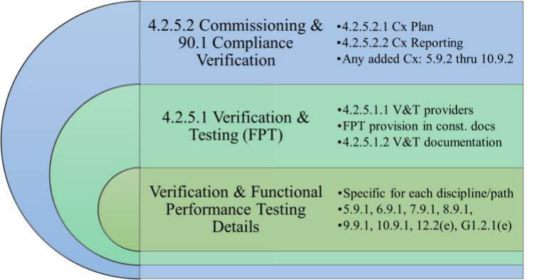
PDF Page 350
Table H-2 Typical Commissioning (Cx) Process Activities, Deliverables and Responsibilities [ a]
| Item | Activity | Deliverable | 90.1 Section | Normally Provided by | Phase |
|---|---|---|---|---|---|
| 1 | Owner’s Project Requirements (OPR) | OPR document | NR | Owner with assistance from design and_Cx_ teams | Predesign |
| 2 | Basis of Design (BoD) | BoD document | NR | Design team | Design through construction |
| 3 | Cx plan | Cx plan document | 4.2.5.2.2 | Cx provider with input from owner, design team, and contractor | Predesign |
| 4 | Contractor_Cx_ requirements | Cx specifications | 4.2.5.1.1, 4.2.5.2.1, 6.9.2 | Design team and Cx provider | Design |
| 5 | Design review, including Standard 90.1 compliance review | Cx design review report | 4.2.5.2, 4.2.5.2.2 | Cx provider | Design |
| 6 | Submittal review | Submittal review report b | NR | Cx provider | Construction |
| 7 | Commission designated systems, inspections,FPT | Installation, inspection, functional test reports, performance test reports b | 4.2.5.1, 4.2.5.2 | Contractors,manufacturers, Cx provider, and_Cx provider team_ | Construction |
| 8 | Track identified issues to resolution | Issues and resolution log b | 4.2.5.1, 4.2.5.2 | Cx provider and team | Construction |
| 9 | Systems manual | Systems manual review | Review NR | Contractors with review by Cx provider | Construction |
| 10 | Training | Training plan and reports b | NR | Contractors and_manufacturers_ with review by_Cx provider_ | Final |
| 11 | Preliminary_Cx_ report | Preliminary Cx report | 4.2.5.2.1, 4.2.5.2.2 | Cx provider | Construction |
| 12 | Cx activities during occupancy | Additional information and updates to reports b | NR | Cx provider and_building_ operations | Final |
| 13 | Final_Cx_ report | Final_Cx_ Report | 4.2.5.2.2 | Cx provider | Final |
a. NR = not required by Standard 90.1; Cx = commissioning. b. Noted interim or partial deliverables are typically included in the preliminary and final commissioning reports.
gested items to verify in that section. There are specific verification, commissioning, or testing activities required by Standard 90.1 in Sections 4.2.5, 5.9, 6.9, 7.9, 8.9, 9.9, 10.9, 12.2(e), and G1.2.1(e). Table H-3 lists only the items in Standard 90.1 that would be beneficial to include in a commissioning scope. While these requirements cover many of the building components, they are not comprehensive, and there are benefits available from additional commissioning or testing. There are other items outside the scope of Standard 90.1 that would typically be included in a commissioning scope that are not covered here but that may improve the quality and reliability of the building systems and assemblies.
The suggested commissioning activities are intended to be included in a commissioning scope based on the building owner’s perception of desired outcomes relative to the particular building program and location and based on the experience of the commissioning provider . The activities are summarized in a checklist format and are related to the requirements that are described in the noted subsections of Standard 90.1. The scope of the items to verify should include verification of compliance with Standard 90.1 requirements by documenting each item’s applicability, inclusion, or exception. Included items should be verified for installation, proper configuration, and operation. Depending on the comprehensiveness of the commissioning effort, verification for certain items may be included at the design phase, construction phase, or both. Verification that the design and construction meet the requirements of the chosen compliance path in Standard 90.1 could be completed using the verification and compliance forms from the Standard 90.1 User’s Man- ual . Table H-3 could be used as a commissioning scope development checklist, and for each item the status for the subject building could be noted as follows:
NA = not applicable (Either the item is not in the proposed building, an exception was used, or the item or prescriptive requirement was traded off in the performance path.)
Cx = commissioned, verified, or tested
348 ANSI/ASHRAE/IES Standard 90.1-2022 (I-P)
PDF Page 351
Table H-3 Standard 90.1 Items to Verify
| Subsection | Subsection Title | Standard 90.1 Items to Verify for Proper Operation or Inclusion | Status |
|---|---|---|---|
| 4.2.5.2 | Building Commissioning Requirements | Document in sufficient detail compliance of the_building_ and its components, assemblies, controls, and_systems_ with required provisions of this standard. | |
| 5.4.1 | Insulation | Design details maintain continuity of thermal barrier. | |
| 5.4.3.2 | Continuous Air Barrier Design and Installation | Air barriers meet the following: • Air barrier design and installation per Section 5.4.3.2 and either • whole-building air leakage testing per Section 5.4.3.1 or • design and installation verification program performed in accordance with Section 5.4.3.1 and Section 5.9.1.2. | |
| 5.8.3.1 | Testing, Acceptable Materials, and Assemblies | Continuous air barrier materials and assemblies comply with specific manufacturer requirements or are tested for leakage resistance. | |
| 5.8.3.2 | Fenestration and Doors | Fenestration and_doors_ have_manufacturer_ documentation that_air leakage_ does not exceed allowable_air leakage_ rates. | |
| 5.5.4.2 | Fenestration Area | Fenestration to_wall_ ratio and_skylight_ to_roof_ ratio meet either the prescriptive requirements or the_proposed design_ in the performance path, depending on the compliance path used. | |
| 5.8.1 | Insulation | Insulation material meets design specifications and is continuous. | |
| 5.9 | Verification, Testing, and Commissioning | Envelope assemblies and_fenestration_ comply with requirements.Building envelope performance is tested or verified. | |
| 6.3.2 | Criteria | HVAC_equipment_ meets_efficiency_ criteria and controls function properly. | |
| 6.4.1 | Equipment Efficiencies, Verification, and Labeling Requirements | Equipment selected meets the minimum_efficiency_ requirements and is correctly_labeled._ | |
| 6.4.2 | Calculations | HVAC_equipment_ matches load and_pump_ head calculations. | |
| 6.4.3.1/ 6.4.3.2 | Zone Thermostatic Controls/ Set-Point Overlap Restriction | Zoning pattern and_dead band_ setting configured properly, including_VAV_ zone controls. Heating and cooling_set points_ do not overlap. | |
| 6.4.3.3 | Off-Hour Controls | Off-hour control,automatic shutdown,setback controls, optimum start control, and zone isolation are properly configured where applicable. | |
| 6.4.3.4 | Ventilation System Controls | Stair and shaft_automatic_ damper function, shutoff damper control, damper leakage performance, ventilation fans, and enclosed parking garage control systems operate per code. | |
| 6.4.3.5 | Heat-Pump Auxiliary Heat Control | Heat-pump auxiliary heat control properly configured. | |
| 6.4.3.6 | Humidifier Preheat | Automatic shutoff valve with configured controls. | |
| 6.4.3.6 | Humidification and Dehumidification Control | No simultaneous humidification and dehumidification operation. | |
| 6.4.3.7 | Freeze Protection and Ice/Snow Melt | Automatic shutoff based on outdoor temperature or precipitation. | |
| 6.4.3.8 | Ventilation Controls for High-Occupancy Areas | Demand control ventilation (DCV) system where applicable. | |
| 6.4.3.10 | Single-Zone VAV Control | Single-zone systems have multispeed or_VAV_ control properly configured. | |
| 6.4.4.1 | HVAC System Insulation | Insulation for ductwork,piping, heating panels, and radiant floor heating systems correct and continuous. | |
| 6.4.4.2 | Ductwork and Plenum Leakage | Duct sealing complete, and required leakage tests performed. |
ANSI/ASHRAE/IES Standard 90.1-2022 (I-P) 349
PDF Page 352
Table H-3 Standard 90.1 Items to Verify (Continued)
| Subsection | Subsection Title | Standard 90.1 Items to Verify for Proper Operation or Inclusion | Status |
|---|---|---|---|
| 6.5.1.1 | Air Economizers | Outdoor air and return air damper control sequence properly configured. High- limit shutoff set properly. Damper leakage and relief air appropriate. Sensor accuracy and calibration. | |
| 6.5.1.2 | Fluid Economizers | Maximum pressure drop (precooling coils, water-to-water heat exchanger). Economizer control integration sequence with heating,mechanical cooling, and inside humidity. | |
| 6.5.2.1 | Zone Controls | Zone box minimum position and operating sequence,deadband, and_set points_ configured properly. | |
| 6.5.2.2 | Hydronic System Controls | Two-pipe changeover control_dead band_ and hydronic heat-pump_system_ controls configured properly. | |
| 6.5.2.3/ 6.5.2.4 | Dehumidification/ Humidification | Humidistatic controls configured properly if applicable. | |
| 6.5.2.5 | Preheat Coils | Control sequence configured properly. | |
| 6.5.3.1 | Fan System Power and Efficiency | Fans are within power limits or meet_efficiency_ requirements. | |
| 6.5.3.2 | Fan Control | Fans are equipped with variable-speed drives or multispeed control where required, and control sensors and sequence are properly implemented.VAV static pressure_set point_ is_reset._ | |
| 6.5.3.3 | Multiple-Zone VAV System Ventilation Optimization Control | Proper configuration of ventilation optimization controls for_VAV systems_. | |
| 6.5.3.4 | Parallel-Flow Fan-Powered VAV Air-Terminal Control | Check for proper sequence control. | |
| 6.5.3.5 | Supply Air Temperature Reset Controls | Proper operation of supply air_reset_ controls for multiple zone systems. | |
| 6.5.3.6 | Fractional Horsepower Fan Motors | For smaller fans, ECM or equivalent_efficiency_ motors have speed control. | |
| 6.5.4.1 | Boiler Turndown | Boiler turndown capability and plant load controls for multiple_boilers_ or modulating burner operation. | |
| 6.5.4.2 | Hydronic Variable Flow Systems | Hydronic systems are variable flow and equipped with_pump_ speed controls where required. | |
| 6.5.4.3 | Chiller and Boiler Isolation | Offline chillers and_boilers_ are properly isolated and_automatic_ controls function as required. | |
| 6.5.4.4 | Chilled- and Hot-Water Temperature Reset Controls | Hydronic temperature_reset_ controls are configured properly where required. | |
| 6.5.6 | Energy Recovery | Energy recovery systems implemented where required for exhaust air_energy_ recovery and service hot-water heat recovery. | |
| 6.5.7 | Exhaust Systems | Proper operation of kitchen and laboratory exhaust air systems where required for demand ventilation including integration of makeup-air units with performance testing at multiple flow rates. | |
| 6.5.8 | Radiant Heating Systems | Radiant heating system controls operate properly and are coordinated with other zone controls. | |
| 6.5.10 | Door Switches | Door switches provide proper control integration. | |
| 6.5.11 | Refrigeration Systems | Refrigeration control elements are properly configured. |
350 ANSI/ASHRAE/IES Standard 90.1-2022 (I-P)
PDF Page 353
Table H-3 Standard 90.1 Items to Verify (Continued)
| Subsection | Subsection Title | Standard 90.1 Items to Verify for Proper Operation or Inclusion | Status |
|---|---|---|---|
| 6.9 | Verification, Testing, and Commissioning | HVAC control_systems_ receive testing for proper operation in accordance with Sections 6.9 and 4.2.5. See specific items in Sections 6.4 and 6.5. | |
| 7.4.4 | Service Water Heating System Controls | Proper configuration of temperature and circulation_pump_ controls. | |
| 7.4.5.3 | Time Switches | Proper configuration of_pool_ heater and_pump_ controls. | |
| 8.4.2 | Automatic Receptacle Control | Proper control integration of required receptacle and labeling of controlled receptacles. | |
| 8.4.3 | Electrical Energy Monitoring | Proper assignment of electrical loads for required end-use monitoring. | |
| 9.4.1.1 | Interior Lighting Control | Proper operation of lighting controls, including local control, bilevel control. | |
| 9.4.1.2 | Parking Garage Lighting Control | Proper operation of parking lot lighting controls, including_occupancy sensor_, time switch, and daylighting control. | |
| 9.4.1.3 | Special Applications | Proper operation of lighting controls, including separate control of display, accent, display case, hotel guest room, nonvisual, and demonstration lighting. | |
| 9.4.1.4 | Exterior Lighting Control | Proper operation of exterior lighting controls, including parking area proximity sensors, time switch, and photocell or astronomical time control. | |
| 9.9.1 | Verification and Testing | Required functional testing is completed for occupant sensors,automatic time switches, and daylight responsive control. Include control items in Sections 9.4.1.1 through 9.4.1.4. | |
| 10.4.2 | Service Water Pressure Booster Systems | Required functional testing is completed for service water pressure booster system controls. | |
| 10.4.5 | Air Curtains | Functional testing and adjustment per the_manufacturer’s_ installation requirements | |
| 11.5.1 | Energy Credits Required | Adequate_energy_ credits are included in the project to meet the requirements of the_building_ type and climate zone. | |
| 11.5.2 | Energy Credits Achieved | If applicable, test or commission any items in the proposed_building_ not already covered in Sections 5 through 10 required to achieve the_energy_ efficiency to meet the_energy_ credits required for the_building_ type and climate zone. | |
| 12.2(d), and G1.2.1(c) | (Energy cost budget and performance paths) | If applicable, test or commission any items in the proposed_building_ not already covered in Sections 5 through 10 required to achieve the_energy_ efficiency to meet the chosen performance path. |
Commissioning processes and the chosen items to verify can vary based on many factors. Selection of items to verify will be based on the specific project requirements, specific systems, building configuration, and climate zone. Some items may not apply at all in particular buildings . If the Energy Cost Budget Method or Performance Rating Method is used for compliance, the items to verify include any additional efficiency features of the proposed building design that are required for the building to comply using the selected performance path. The list in Table H-3 includes both mandatory items and prescriptive items. The prescriptive items may be adjusted or traded off in one of the performance paths.
H5. COMMISSIONING DOCUMENTATION
The commissioning process typically results in the deliverables included in this section. There may also be interim partial deliverables (as noted in Table H-2) or online issue tracking systems. Standard 90.1 does not require all of these documents; however, they are all part of a complete commissioning process. Where Standard 90.1 has specific requirements, references to the relevant Standard 90.1 sections are included. A document not required by Standard 90.1 is flagged “NR by 90.1.” This section provides background on the general content of these documents, with information about how they support the goals of Standard 90.1.
ANSI/ASHRAE/IES Standard 90.1-2022 (I-P) 351
PDF Page 354
Detailed information about the recommended contents of each of these documents can be found in ASHRAE Guideline 0 and other commissioning resources.
H5.1 Owner’s Project Requirements (OPR) (NR by 90.1). The Owner’s Project Requirements (OPR) is a document developed by the owner with assistance from the design and commissioning teams that details the requirements of a project and the expectations for how it will be used and operated. The OPR should include project goals, measurable performance criteria, cost considerations, benchmarks, success criteria, and supporting information. The term “project intent” or “design intent” is used by some owners for their commis- sioning process OPR. The OPR supports the energy efficiency goals of Standard 90.1 by clarifying energy efficiency goals for the building from the owner’s perspective. These goals can be referenced when defending against value engineering efforts that may eliminate efficiency measures without considering long-term building life-cycle cost.
H5.2 Basis of Design (BoD) (NR by 90.1). The Basis of Design (BoD) is a document developed by the design team that records the concepts, calculations, decisions, and product selections used to meet the OPR and to satisfy applicable regulatory requirements, standards, and guidelines. The document should include both narrative descriptions and lists of individual items that support the design process. The BoD supports the energy efficiency goals of Standard 90.1 by clarifying the criteria on which the building system design is based, so that full-load and part-load energy efficiency goals are met. In cases where a BoD is not separately developed, it can be inferred from the preliminary construction documents for purposes of developing a commissioning plan.
H5.3 Commissioning Plan (See Section 4.2.5.2.2). The commissioning plan is a document developed by a commissioning provider that supports the energy efficiency goals of Standard 90.1 by clarifying the commis- sioning activities throughout the design and construction process and how they are integrated into design team and contractor activities. The commissioning plan is also useful in providing the building official with assurance that required commissioning activities will be performed.
H5.4 Contractor Commissioning Requirements (See Sections 4.2.5.1.1, 4.2.5.2.1, and 6.9.2). The com- missioning provider works with the design team to ensure that contractor requirements for involvement in the commissioning process are included in the construction documents . The contractor commissioning requirements support the energy efficiency goals of Standard 90.1 by ensuring that the contractor supports and allows for the commissioning activities within the construction process.
H5.5 Commissioning Design Review Report and Standard 90.1 Compliance Review (See Sections 4.2.5.2 and 4.2.5.2.2). The commissioning provider provides a design review ( commissioning design review report) to the owner and design teams to report compliance with the OPR and BoD. The review includes verification that the design meets the requirements of the chosen path in Standard 90.1, which could be completed using the verification forms from the Standard 90.1 User’s Manual . This commissioning design review is not intended to replace a design peer review or a code or regulatory review. The design review supports the energy efficiency goals of Standard 90.1 by verifying that the design substantially meets the requirements of Standard 90.1. If areas of the design are found to not meet the requirements, the design can be changed at a lower cost before construction begins, avoiding costly change orders during construction .
H5.6 Record Documents (See Sections 4.2.2.1, 6.7.3.1, 8.7.3.1, 9.7.3.1). Record documents are provided to the owner upon project completion. The record documents should be accessible to the building operations and maintenance personnel. The record documents should be included in or referenced by the systems manual. The record documents support the energy efficiency goals of Standard 90.1 by providing information on the design and system criteria so that the operating staff or designers for renovations or upgrades to the building in the future can maintain the specified system efficiency .
H5.7 Systems Manual (See Sections 4.2.2.3, 6.7.3.2, 8.7.3.2, 9.7.3.2). A systems manual supports the energy efficiency goals of Standard 90.1 by providing information on system maintenance and operation so that the operating staff can maintain the specified system efficiency . Including review of the systems manual in the commissioning process will improve the quality of the manuals and make sure that relevant information to the specific building systems operation is included rather than just generic product information. A systems manual should be provided before building operations training for use in the training process. The owner should make the systems manual accessible to the building operations and maintenance personnel throughout the life of the building and ensure that updates are made as the building systems change.
H5.8 Preliminary Commissioning Report (See Section 4.2.5.2.2). A preliminary commissioning report is provided by the commissioning provider and includes the results of the commissioning activities up to the time of occupancy. The results of FPT and other verification is included. The preliminary commissioning report supports the energy efficiency goals of Standard 90.1 by identifying that control sequences related to
352 ANSI/ASHRAE/IES Standard 90.1-2022 (I-P)
PDF Page 355
energy efficiency are working properly, the commissioning plan is useful in providing the building official with assurance that required are in place, where the building official may not have to time or expertise to investigate proper operation. Issues that are unresolved are also identified, as are items that will be tested after occupancy.
H5.9 Final Commissioning Report (See Section 4.2.5.2.2). A final commissioning report is provided by the commissioning provider once all testing is complete. While the final commissioning report is delivered after the occupancy permit, the requirement for it in the construction documents supports the energy effi- ciency goals of Standard 90.1 by providing a future report that will address issues that cannot be resolved at the time of occupancy permit issuance.
ANSI/ASHRAE/IES Standard 90.1-2022 (I-P) 353
PDF Page 356
(This appendix is not part of this standard. It is merely informative and does not contain requirements necessary for conformance to the standard. It has not been processed according to the ANSI require- ments for a standard and may contain material that has not been subject to public review or a consen- sus process. Unresolved objectors on informative material are not offered the right to appeal at ASHRAE or ANSI.)
INFORMATIVE APPENDIX I USING OTHER METRICS IN CONJUNCTION WITH APPENDIX G PERFORMANCE RATING METHOD WHEN APPROVED BY THE RATING AUTHORITY
I1. GENERAL
This informative appendix describes changes to Section 3, Section 4, and Normative Appendix G for using metrics other than energy cost—including site energy, source energy, and carbon emissions—that may be adopted by the rating authority for the Normative Appendix G Performance Rating Method . It also provides methodology for determining building performance factors (BPFs) that should be used in conjunction with custom energy conversion factors other than the national average defaults in Table I5-1.
I2. CHANGES TO SECTION 3
Replace references to “annual energy cost” with the reference to the selected metric in the definitions of baseline building performance and proposed building performance .
I3. CHANGES TO SECTION 4
a. Replace all references to “ energy cost” in Section 4.2.1.1 with “ site energy,” “source energy,” or “carbon
emissions,” as appropriate, throughout. b. Replace all references to “Performance Cost Index” in Section 4.2.1.1 with “Performance Index (Site
Energy),” “Performance Index (Source Energy),” or “Performance Index (Carbon Emissions),” as appropriate throughout. c. For site energy, replace Table 4.2.1.1 with Table I3-1. d. For carbon emissions, replace Table 4.2.1.1 with Table I3-2. e. For source energy, replace Table 4.2.1.1 with Table I3-3.
I4. CHANGES TO NORMATIVE APPENDIX G
a. Replace references to “ energy cost” with references to “ site energy,” “source energy,” or “carbon emis sions” as appropriate in Sections G1.2.2, G1.3.2, G2.1, G2.4.2, and G2.5 section headings. b. Remove the first sentence and informative note in Section G2.4.2, and replace it with the conversion fac tors from Table I4-1 for the selected metric. c. Add an exception to Section G2.4.2 to allow using alternative conversion factors as appropriate for
building location and as approved by the adopting authority .
I5. METHODOLOGY FOR BPF ADJUSTMENT TO ACCOUNT FOR LOCALIZED CONVERSION FACTORS
The BPF values in Table 4.2.1.1, based on energy cost, and the values in Tables I3-1, I3-2, and I3-3, are based on the coefficients in Tables I5-2 through I5-4 and the electricity and fossil fuel conversion factors in Table I5-1. The values in Table I5-1 represent U.S. national average values. The U.S. national conversion factors may not be appropriate for all locations, and some jurisdictions may want to adopt custom conversion factors other than those shown in Table I5-1. When energy conversion factors other than those specified in Table I5-1 are used, the BPFs should also be updated in accordance with Equation I-1.
BPF i,j = (EC + Ai,j × GC)/( Bi,j × EC + Ci,j × GC) (I-1)
Ai,j, Bi,j, Ci,j = coefficients from Tables I5-2, I5-3, and I5-4 for building area type i and climate zone j
EC = custom electricity conversion factor expressed using the units shown in Table I5-1 for the selected metric
GC = custom natural gas conversion factor expressed using the units shown in Table I5-1 for the selected metric
354 ANSI/ASHRAE/IES Standard 90.1-2022 (I-P)
PDF Page 357
Table I3-1 Building Performance Factors (BPF), Site Energy
| Building Area Type | Climate Zone | Col3 | Col4 | Col5 | Col6 | Col7 | Col8 | Col9 | Col10 | Col11 | Col12 | Col13 | Col14 | Col15 | Col16 | Col17 | Col18 | Col19 | Col20 |
|---|---|---|---|---|---|---|---|---|---|---|---|---|---|---|---|---|---|---|---|
| Building Area Type | 0A | 0B | 1A | 1B | 2A | 2B | 3A | 3B | 3C | 4A | 4B | 4C | 5A | 5B | 5C | 6A | 6B | 7 | 8 |
| Multifamily | 0.72 | 0.71 | 0.75 | 0.73 | 0.76 | 0.76 | 0.77 | 0.75 | 0.70 | 0.61 | 0.71 | 0.64 | 0.56 | 0.63 | 0.63 | 0.54 | 0.57 | 0.54 | 0.56 |
| Healthcare/hospital | 0.67 | 0.66 | 0.68 | 0.65 | 0.65 | 0.61 | 0.62 | 0.64 | 0.63 | 0.62 | 0.63 | 0.61 | 0.65 | 0.63 | 0.68 | 0.64 | 0.68 | 0.69 | 0.71 |
| Hotel/motel | 0.69 | 0.69 | 0.72 | 0.68 | 0.69 | 0.68 | 0.69 | 0.70 | 0.71 | 0.65 | 0.69 | 0.68 | 0.63 | 0.66 | 0.67 | 0.60 | 0.64 | 0.59 | 0.58 |
| Office | 0.54 | 0.54 | 0.53 | 0.52 | 0.52 | 0.52 | 0.50 | 0.54 | 0.47 | 0.47 | 0.52 | 0.48 | 0.49 | 0.52 | 0.49 | 0.48 | 0.50 | 0.43 | 0.46 |
| Restaurant | 0.64 | 0.61 | 0.60 | 0.59 | 0.60 | 0.57 | 0.61 | 0.62 | 0.61 | 0.66 | 0.65 | 0.66 | 0.69 | 0.69 | 0.68 | 0.71 | 0.71 | 0.72 | 0.74 |
| Retail | 0.51 | 0.49 | 0.48 | 0.48 | 0.44 | 0.43 | 0.43 | 0.44 | 0.44 | 0.47 | 0.45 | 0.50 | 0.52 | 0.47 | 0.52 | 0.52 | 0.50 | 0.48 | 0.49 |
| School | 0.52 | 0.57 | 0.57 | 0.56 | 0.52 | 0.53 | 0.53 | 0.52 | 0.55 | 0.42 | 0.49 | 0.53 | 0.44 | 0.50 | 0.51 | 0.43 | 0.42 | 0.42 | 0.44 |
| Warehouse | 0.26 | 0.26 | 0.22 | 0.25 | 0.21 | 0.22 | 0.25 | 0.21 | 0.18 | 0.38 | 0.27 | 0.31 | 0.46 | 0.37 | 0.31 | 0.49 | 0.42 | 0.43 | 0.47 |
| All others | 0.63 | 0.62 | 0.65 | 0.61 | 0.56 | 0.53 | 0.55 | 0.55 | 0.59 | 0.55 | 0.55 | 0.58 | 0.57 | 0.57 | 0.61 | 0.57 | 0.57 | 0.56 | 0.58 |
Table I3-2 Building Performance Factors (BPF), Carbon Emission
| Building Area Type | Climate Zone | Col3 | Col4 | Col5 | Col6 | Col7 | Col8 | Col9 | Col10 | Col11 | Col12 | Col13 | Col14 | Col15 | Col16 | Col17 | Col18 | Col19 | Col20 |
|---|---|---|---|---|---|---|---|---|---|---|---|---|---|---|---|---|---|---|---|
| Building Area Type | 0A | 0B | 1A | 1B | 2A | 2B | 3A | 3B | 3C | 4A | 4B | 4C | 5A | 5B | 5C | 6A | 6B | 7 | 8 |
| Multifamily | 0.71 | 0.69 | 0.73 | 0.71 | 0.74 | 0.74 | 0.74 | 0.75 | 0.67 | 0.64 | 0.73 | 0.67 | 0.60 | 0.67 | 0.66 | 0.59 | 0.61 | 0.58 | 0.60 |
| Healthcare/hospital | 0.68 | 0.67 | 0.69 | 0.67 | 0.66 | 0.63 | 0.64 | 0.65 | 0.63 | 0.63 | 0.65 | 0.62 | 0.66 | 0.64 | 0.67 | 0.65 | 0.67 | 0.69 | 0.70 |
| Hotel/motel | 0.67 | 0.67 | 0.70 | 0.66 | 0.67 | 0.66 | 0.66 | 0.68 | 0.68 | 0.64 | 0.67 | 0.65 | 0.63 | 0.65 | 0.65 | 0.61 | 0.63 | 0.59 | 0.58 |
| Office | 0.54 | 0.54 | 0.53 | 0.52 | 0.52 | 0.52 | 0.50 | 0.54 | 0.48 | 0.47 | 0.52 | 0.48 | 0.49 | 0.52 | 0.49 | 0.48 | 0.50 | 0.45 | 0.47 |
| Restaurant | 0.63 | 0.60 | 0.59 | 0.58 | 0.58 | 0.55 | 0.59 | 0.58 | 0.56 | 0.61 | 0.60 | 0.60 | 0.64 | 0.63 | 0.62 | 0.66 | 0.66 | 0.68 | 0.70 |
| Retail | 0.51 | 0.49 | 0.48 | 0.48 | 0.44 | 0.43 | 0.43 | 0.43 | 0.44 | 0.44 | 0.44 | 0.48 | 0.47 | 0.45 | 0.49 | 0.47 | 0.46 | 0.45 | 0.47 |
| School | 0.52 | 0.57 | 0.57 | 0.56 | 0.52 | 0.53 | 0.53 | 0.51 | 0.52 | 0.44 | 0.48 | 0.50 | 0.45 | 0.48 | 0.48 | 0.45 | 0.43 | 0.43 | 0.45 |
| Warehouse | 0.26 | 0.26 | 0.22 | 0.25 | 0.21 | 0.22 | 0.25 | 0.21 | 0.18 | 0.31 | 0.24 | 0.27 | 0.38 | 0.31 | 0.26 | 0.41 | 0.36 | 0.37 | 0.41 |
| All others | 0.63 | 0.61 | 0.63 | 0.60 | 0.55 | 0.52 | 0.54 | 0.54 | 0.57 | 0.54 | 0.53 | 0.56 | 0.55 | 0.55 | 0.58 | 0.56 | 0.56 | 0.55 | 0.56 |
Table I3-3 Building Performance Factors (BPF), Source Energy
| Building Area Type | Climate Zone | Col3 | Col4 | Col5 | Col6 | Col7 | Col8 | Col9 | Col10 | Col11 | Col12 | Col13 | Col14 | Col15 | Col16 | Col17 | Col18 | Col19 | Col20 |
|---|---|---|---|---|---|---|---|---|---|---|---|---|---|---|---|---|---|---|---|
| Building Area Type | 0A | 0B | 1A | 1B | 2A | 2B | 3A | 3B | 3C | 4A | 4B | 4C | 5A | 5B | 5C | 6A | 6B | 7 | 8 |
| Multifamily | 0.70 | 0.69 | 0.72 | 0.71 | 0.73 | 0.73 | 0.73 | 0.75 | 0.65 | 0.66 | 0.74 | 0.69 | 0.63 | 0.69 | 0.68 | 0.61 | 0.63 | 0.60 | 0.63 |
| Healthcare/hospital | 0.69 | 0.68 | 0.70 | 0.67 | 0.66 | 0.64 | 0.64 | 0.66 | 0.64 | 0.64 | 0.65 | 0.63 | 0.66 | 0.64 | 0.66 | 0.66 | 0.67 | 0.68 | 0.70 |
| Hotel/motel | 0.66 | 0.67 | 0.70 | 0.66 | 0.66 | 0.65 | 0.65 | 0.67 | 0.66 | 0.63 | 0.66 | 0.64 | 0.62 | 0.64 | 0.64 | 0.61 | 0.62 | 0.59 | 0.58 |
| Office | 0.54 | 0.54 | 0.53 | 0.52 | 0.52 | 0.52 | 0.50 | 0.54 | 0.48 | 0.47 | 0.53 | 0.48 | 0.49 | 0.52 | 0.49 | 0.48 | 0.50 | 0.45 | 0.47 |
| Restaurant | 0.63 | 0.59 | 0.58 | 0.57 | 0.58 | 0.54 | 0.58 | 0.56 | 0.54 | 0.59 | 0.57 | 0.57 | 0.61 | 0.60 | 0.59 | 0.64 | 0.62 | 0.65 | 0.68 |
| Retail | 0.51 | 0.49 | 0.48 | 0.48 | 0.44 | 0.43 | 0.43 | 0.43 | 0.44 | 0.43 | 0.43 | 0.47 | 0.45 | 0.43 | 0.48 | 0.45 | 0.45 | 0.43 | 0.45 |
| School | 0.52 | 0.57 | 0.57 | 0.56 | 0.52 | 0.53 | 0.53 | 0.50 | 0.51 | 0.44 | 0.47 | 0.49 | 0.46 | 0.47 | 0.47 | 0.45 | 0.43 | 0.44 | 0.45 |
| Warehouse | 0.26 | 0.26 | 0.22 | 0.25 | 0.21 | 0.22 | 0.25 | 0.21 | 0.18 | 0.28 | 0.23 | 0.25 | 0.34 | 0.28 | 0.25 | 0.37 | 0.32 | 0.34 | 0.37 |
| All others | 0.62 | 0.61 | 0.63 | 0.60 | 0.55 | 0.52 | 0.54 | 0.53 | 0.56 | 0.54 | 0.53 | 0.56 | 0.54 | 0.54 | 0.57 | 0.55 | 0.55 | 0.55 | 0.56 |
ANSI/ASHRAE/IES Standard 90.1-2022 (I-P) 355
PDF Page 358
Table I4-1 Energy Conversion Factors (see Note 1)
| Building Project Energy Source | Units | Carbon Emissions CO 2e lb/unit | Site Energy, Btu/unit (see Note 2) | Source Energy, Btu/unit |
|---|---|---|---|---|
| Electricity | kWh | 1.20 | 3412 | 9008 |
| Natural gas | Therm (GJ) | 19.96 | 100,000 | 109,000 |
| Propane | Therm (GJ) | 19.080 | 100,000 | 115,000 |
| Distillate fuel oil | Gallon (L) | 28.330 | 137,600 | 163,744 |
Notes:
- These conversions are based on national averages for the United States and may not be representative for other locations. Jurisdictions that choose to use localized conversion factors for source energy or carbon emissions should update the corresponding BPF table for consistency using methodology in Section I5. Jurisdictions may add conversion factors for other energy sources.
- Site energy only accounts for energy as measured at the building site. It does not account for the energy consumed in the extraction, processing, and transport of primary energy, nor energy consumed in conversion to electricity in power-generation plants.
Table I5-1 National Average Energy Conversion Factors Used to Calculate BPF
| Metric | Site Energy | Carbon Emissions CO 2e | Source Energy | Energy Cost |
|---|---|---|---|---|
| Units | site kBtu/site kBtu | lb/site kBtu | source kBtu/site kBtu | $/site kBtu |
| Electric conversion factors | 1.0 | 0.353 | 2.64 | 0.03221 |
| Natural gas conversion factors | 1.0 | 0.200 | 1.090 | 0.00802 |
| Table I5-2 | Coefficient A Values | Col3 | Col4 | Col5 | Col6 | Col7 | Col8 | Col9 | Col10 | Col11 | Col12 | Col13 | Col14 | Col15 | Col16 | Col17 | Col18 | Col19 | Col20 |
|---|---|---|---|---|---|---|---|---|---|---|---|---|---|---|---|---|---|---|---|
| Building Area Type | Climate Zone | Climate Zone | Climate Zone | Climate Zone | Climate Zone | Climate Zone | Climate Zone | Climate Zone | Climate Zone | Climate Zone | Climate Zone | Climate Zone | Climate Zone | Climate Zone | Climate Zone | Climate Zone | Climate Zone | Climate Zone | Climate Zone |
| Building Area Type | 0A | 0B | 1A | 1B | 2A | 2B | 3A | 3B | 3C | 4A | 4B | 4C | 5A | 5B | 5C | 6A | 6B | 7 | 8 |
| Multifamily | 0.3006 | 0.3261 | 0.4321 | 0.4064 | 0.5158 | 0.5445 | 0.7128 | 0.6952 | 1.1709 | 1.1302 | 0.8644 | 1.2685 | 1.5138 | 1.1288 | 1.3067 | 1.7228 | 1.5398 | 1.8543 | 2.1737 |
| Health care/ hospital | 0.1250 | 0.1412 | 0.1507 | 0.1544 | 0.1979 | 0.1602 | 0.2319 | 0.2098 | 0.2688 | 0.3262 | 0.2596 | 0.3865 | 0.4926 | 0.3624 | 0.5972 | 0.6143 | 0.6194 | 0.8438 | 1.0747 |
| Hotel/motel | 0.2711 | 0.2833 | 0.3267 | 0.3373 | 0.3922 | 0.4544 | 0.5143 | 0.6042 | 0.6922 | 0.8420 | 0.7668 | 0.9723 | 1.0639 | 0.9353 | 1.0888 | 1.2454 | 1.1995 | 1.4783 | 1.9709 |
| Office | 0.0000 | 0.0000 | 0.0000 | 0.0000 | 0.0000 | 0.0000 | 0.0000 | 0.0425 | 0.0105 | 0.2479 | 0.0868 | 0.2155 | 0.4409 | 0.2496 | 0.2634 | 0.6874 | 0.5018 | 0.6405 | 0.9613 |
| Restaurant | 0.2210 | 0.2418 | 0.3366 | 0.3120 | 0.3984 | 0.4813 | 0.5416 | 0.8752 | 1.0794 | 1.8987 | 1.3855 | 2.0956 | 2.9552 | 2.1791 | 2.6220 | 3.7419 | 3.1353 | 4.8743 | 7.2168 |
| Retail | 0.0000 | 0.0000 | 0.0000 | 0.0000 | 0.0000 | 0.0000 | 0.0000 | 0.0509 | 0.0056 | 0.4874 | 0.1141 | 0.3074 | 0.8526 | 0.3748 | 0.3778 | 1.1246 | 0.6886 | 1.1802 | 1.5119 |
| School | 0.0346 | 0.0368 | 0.0447 | 0.0461 | 0.0581 | 0.0703 | 0.0791 | 0.2052 | 0.2586 | 0.3806 | 0.3220 | 0.7076 | 0.6664 | 0.6527 | 0.7928 | 0.9529 | 0.7842 | 1.1857 | 2.0419 |
| Warehouse | 0.0000 | 0.0000 | 0.0000 | 0.0000 | 0.0000 | 0.0000 | 0.0000 | 0.1323 | 0.0158 | 2.6058 | 0.8393 | 1.2916 | 4.6583 | 2.2657 | 1.2302 | 6.2218 | 3.8034 | 5.9278 | 6.3860 |
| All others | 0.1552 | 0.1668 | 0.2257 | 0.2050 | 0.1784 | 0.1568 | 0.2015 | 0.3111 | 0.4107 | 0.7223 | 0.3880 | 0.7372 | 1.0594 | 0.7105 | 0.7100 | 1.2640 | 0.9793 | 1.2947 | 1.8802 |
Table I5-3 Coefficient B Values
| Building Area Type | Climate Zone | Col3 | Col4 | Col5 | Col6 | Col7 | Col8 | Col9 | Col10 | Col11 | Col12 | Col13 | Col14 | Col15 | Col16 | Col17 | Col18 | Col19 | Col20 |
|---|---|---|---|---|---|---|---|---|---|---|---|---|---|---|---|---|---|---|---|
| Building Area Type | 0A | 0B | 1A | 1B | 2A | 2B | 3A | 3B | 3C | 4A | 4B | 4C | 5A | 5B | 5C | 6A | 6B | 7 | 8 |
| Multifamily | 1.472 | 1.504 | 1.440 | 1.472 | 1.434 | 1.433 | 1.455 | 1.318 | 1.701 | 1.314 | 1.263 | 1.305 | 1.283 | 1.259 | 1.288 | 1.248 | 1.278 | 1.251 | 1.153 |
| Health care/hospital | 1.423 | 1.437 | 1.400 | 1.449 | 1.475 | 1.506 | 1.510 | 1.492 | 1.546 | 1.520 | 1.505 | 1.548 | 1.483 | 1.519 | 1.572 | 1.483 | 1.513 | 1.488 | 1.447 |
| Hotel/motel | 1.547 | 1.545 | 1.480 | 1.580 | 1.574 | 1.623 | 1.626 | 1.582 | 1.627 | 1.637 | 1.610 | 1.665 | 1.627 | 1.628 | 1.677 | 1.640 | 1.660 | 1.688 | 1.719 |
| Office | 1.855 | 1.869 | 1.900 | 1.915 | 1.913 | 1.923 | 1.982 | 1.845 | 2.058 | 2.071 | 1.883 | 2.080 | 2.040 | 1.936 | 2.089 | 2.100 | 2.033 | 2.098 | 2.031 |
| Restaurant | 1.622 | 1.724 | 1.788 | 1.807 | 1.813 | 1.978 | 1.837 | 2.036 | 2.172 | 2.086 | 2.118 | 2.219 | 2.122 | 2.164 | 2.232 | 2.113 | 2.160 | 2.156 | 2.192 |
| Retail | 1.961 | 2.057 | 2.078 | 2.090 | 2.286 | 2.353 | 2.345 | 2.372 | 2.296 | 2.511 | 2.360 | 2.233 | 2.573 | 2.486 | 2.187 | 2.649 | 2.516 | 2.715 | 2.525 |
| School | 1.921 | 1.748 | 1.747 | 1.778 | 1.941 | 1.901 | 1.914 | 2.074 | 2.093 | 2.102 | 2.192 | 2.275 | 2.089 | 2.256 | 2.328 | 2.073 | 2.241 | 2.102 | 2.146 |
| Warehouse | 3.885 | 3.804 | 4.454 | 3.994 | 4.692 | 4.591 | 3.967 | 4.884 | 5.296 | 5.724 | 5.241 | 5.472 | 6.045 | 5.572 | 5.419 | 5.962 | 5.558 | 5.935 | 5.477 |
| All others | 1.621 | 1.667 | 1.632 | 1.712 | 1.852 | 1.973 | 1.902 | 1.950 | 1.863 | 1.899 | 1.985 | 1.870 | 1.970 | 1.966 | 1.866 | 1.906 | 1.902 | 1.881 | 1.933 |
356 ANSI/ASHRAE/IES Standard 90.1-2022 (I-P)
PDF Page 359
| Table I5-4 | Coefficient C Values | Col3 | Col4 | Col5 | Col6 | Col7 | Col8 | Col9 | Col10 | Col11 | Col12 | Col13 | Col14 | Col15 | Col16 | Col17 | Col18 | Col19 | Col20 |
|---|---|---|---|---|---|---|---|---|---|---|---|---|---|---|---|---|---|---|---|
| Building Area Type | Climate Zone | Climate Zone | Climate Zone | Climate Zone | Climate Zone | Climate Zone | Climate Zone | Climate Zone | Climate Zone | Climate Zone | Climate Zone | Climate Zone | Climate Zone | Climate Zone | Climate Zone | Climate Zone | Climate Zone | Climate Zone | Climate Zone |
| Building Area Type | 0A | 0B | 1A | 1B | 2A | 2B | 3A | 3B | 3C | 4A | 4B | 4C | 5A | 5B | 5C | 6A | 6B | 7 | 8 |
| Multifamily | 0.3268 | 0.3547 | 0.4698 | 0.4419 | 0.5608 | 0.5921 | 0.7751 | 0.9461 | 1.3802 | 2.1938 | 1.3725 | 2.2150 | 3.1673 | 2.1109 | 2.3514 | 3.7613 | 3.2073 | 4.0765 | 4.5499 |
| Health care/ hospital | 0.2538 | 0.2952 | 0.2924 | 0.3186 | 0.3728 | 0.3966 | 0.4705 | 0.3979 | 0.4800 | 0.6318 | 0.4830 | 0.7239 | 0.8189 | 0.6407 | 0.7623 | 1.0245 | 0.8759 | 1.1802 | 1.4851 |
| Hotel/motel | 0.3054 | 0.3192 | 0.3674 | 0.3794 | 0.4401 | 0.5104 | 0.5758 | 0.7070 | 0.7578 | 1.1950 | 0.9496 | 1.2431 | 1.6502 | 1.2861 | 1.4319 | 2.0806 | 1.7910 | 2.4916 | 3.3918 |
| Office | 0.0000 | 0.0000 | 0.0000 | 0.0000 | 0.0000 | 0.0000 | 0.0000 | 0.0776 | 0.0890 | 0.6078 | 0.2077 | 0.4525 | 0.9224 | 0.4828 | 0.4656 | 1.4263 | 0.9818 | 1.6892 | 2.2766 |
| Restaurant | 0.2876 | 0.3147 | 0.4309 | 0.4001 | 0.5043 | 0.6085 | 0.6731 | 0.9800 | 1.2400 | 2.3208 | 1.5298 | 2.4918 | 3.6117 | 2.4166 | 3.1189 | 4.5816 | 3.6641 | 5.9587 | 8.8807 |
| Retail | 0.0000 | 0.0000 | 0.0000 | 0.0000 | 0.0000 | 0.0000 | 0.0000 | 0.0268 | 0.0031 | 0.6502 | 0.1292 | 0.4050 | 1.0239 | 0.4191 | 0.4873 | 1.4196 | 0.8469 | 1.8038 | 2.5674 |
| School | 0.0574 | 0.0605 | 0.0716 | 0.0734 | 0.0906 | 0.1091 | 0.1185 | 0.2332 | 0.2124 | 1.2081 | 0.5076 | 0.9354 | 1.6698 | 1.0708 | 1.1824 | 2.4336 | 1.9958 | 3.1587 | 4.7541 |
| Warehouse | 0.0000 | 0.0000 | 0.0000 | 0.0000 | 0.0000 | 0.0000 | 0.0000 | 0.4289 | 0.3731 | 3.7923 | 1.5264 | 1.8399 | 6.1674 | 3.2986 | 1.7394 | 8.7227 | 5.8554 | 10.164 | 10.401 |
| All others | 0.2029 | 0.2198 | 0.2640 | 0.2659 | 0.2354 | 0.2239 | 0.2697 | 0.4152 | 0.5288 | 1.2546 | 0.5421 | 1.1404 | 1.6641 | 1.0498 | 0.9435 | 2.0621 | 1.5669 | 2.2440 | 3.0603 |
I6. SITE ENERGY USE LANGUAGE EXAMPLE
The following example shows the recommended changes to Section 3, Section 4.2.1.1, and Table 4.2.1.1, and Sections G1.2.2, G1.3.2, G2.4.2, and G2.5, if the site energy alternative compliance metric is adopted. Example text is highlighted in gray. Example changes are illustrated with strikethrough and underline.
Modify Section 3 as follows:
proposed building performance: the annual site energy cost calculated for a proposed design .
Modify Section 4.2.1.1 as follows:
[ … ]
where
BBP = baseline building performance.
ANSI/ASHRAE/IES Standard 90.1-2022 (I-P) 357

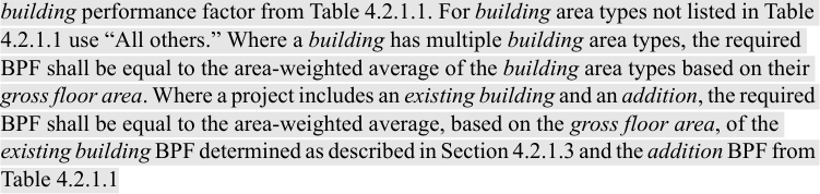
PDF Page 360
PRE = PBP nre - PBP pre
Replace values in Table 4.2.1.1 with the values from Table I3-1 (deleted values not shown):
Table 4.2.1.1 Building Performance Factors (BPF), Site Energy


| Building Area Type | Climate Zone | Col3 | Col4 | Col5 | Col6 | Col7 | Col8 | Col9 | Col10 | Col11 | Col12 | Col13 | Col14 | Col15 | Col16 | Col17 | Col18 | Col19 | Col20 |
|---|---|---|---|---|---|---|---|---|---|---|---|---|---|---|---|---|---|---|---|
| Building Area Type | 0A | 0B | 1A | 1B | 2A | 2B | 3A | 3B | 3C | 4A | 4B | 4C | 5A | 5B | 5C | 6A | 6B | 7 | 8 |
| Multifamily | 0.72 | 0.71 | 0.75 | 0.73 | 0.76 | 0.76 | 0.77 | 0.75 | 0.70 | 0.61 | 0.71 | 0.64 | 0.56 | 0.63 | 0.63 | 0.54 | 0.57 | 0.54 | 0.56 |
| Healthcare/hospital | 0.67 | 0.66 | 0.68 | 0.65 | 0.65 | 0.61 | 0.62 | 0.64 | 0.63 | 0.62 | 0.63 | 0.61 | 0.65 | 0.63 | 0.68 | 0.64 | 0.68 | 0.69 | 0.71 |
| Hotel/motel | 0.69 | 0.69 | 0.72 | 0.68 | 0.69 | 0.68 | 0.69 | 0.70 | 0.71 | 0.65 | 0.69 | 0.68 | 0.63 | 0.66 | 0.67 | 0.60 | 0.64 | 0.59 | 0.58 |
| Office | 0.54 | 0.54 | 0.53 | 0.52 | 0.52 | 0.52 | 0.50 | 0.54 | 0.47 | 0.47 | 0.52 | 0.48 | 0.49 | 0.52 | 0.49 | 0.48 | 0.50 | 0.43 | 0.46 |
| Restaurant | 0.64 | 0.61 | 0.60 | 0.59 | 0.60 | 0.57 | 0.61 | 0.62 | 0.61 | 0.66 | 0.65 | 0.66 | 0.69 | 0.69 | 0.68 | 0.71 | 0.71 | 0.72 | 0.74 |
| Retail | 0.51 | 0.49 | 0.48 | 0.48 | 0.44 | 0.43 | 0.43 | 0.44 | 0.44 | 0.47 | 0.45 | 0.50 | 0.52 | 0.47 | 0.52 | 0.52 | 0.50 | 0.48 | 0.49 |
| School | 0.52 | 0.57 | 0.57 | 0.56 | 0.52 | 0.53 | 0.53 | 0.52 | 0.55 | 0.42 | 0.49 | 0.53 | 0.44 | 0.50 | 0.51 | 0.43 | 0.42 | 0.42 | 0.44 |
| Warehouse | 0.26 | 0.26 | 0.22 | 0.25 | 0.21 | 0.22 | 0.25 | 0.21 | 0.18 | 0.38 | 0.27 | 0.31 | 0.46 | 0.37 | 0.31 | 0.49 | 0.42 | 0.43 | 0.47 |
| All others | 0.63 | 0.62 | 0.65 | 0.61 | 0.56 | 0.53 | 0.55 | 0.55 | 0.59 | 0.55 | 0.55 | 0.58 | 0.57 | 0.57 | 0.61 | 0.57 | 0.57 | 0.56 | 0.58 |
Modify Section G1.2.2 as follows:
Modify Section G1.3.2(a) and G1.3.2(p) as follows:
[ … ]
The following documentation shall be submitted to the rating authority :
358 ANSI/ASHRAE/IES Standard 90.1-2022 (I-P)
PDF Page 361
[ … ]
Modify Section G2.4.2 as follows:
Table G2.1 Units of Fuel to Site Energy Conversion Factors

| Building Project Energy Source | Units | Site Energy, Btu/unit |
|---|---|---|
| Electricity | kWh | 3412 |
| Natural gas | therm | 100,000 |
| Propane | therm | 100,000 |
| Distillate fuel oil | gal | 137,600 |
Modify Section G2.5(e) as follows:
[ … ]
e. The Performance Cost Index calculated with and without the exceptional calculation method.
ANSI/ASHRAE/IES Standard 90.1-2022 (I-P) 359
PDF Page 362
(This is a normative appendix and is part of this standard.)
NORMATIVE APPENDIX J SETS OF PERFORMANCE CURVES
J1. GENERAL
J1.1 Description. This appendix provides sets of performance curves that shall be used to represent the part-load performance of chillers in the budget building design when using Section 12 and in the baseline building design when using Normative Appendix G. They are also permitted to be used for the proposed building design when specific chiller performance is not known.
Each set includes three curves: an energy-input-ratio modifier as a function of temperatures (EIR-f-T) and as a function of a chiller’s part-load ratio (EIR-f-PLR), and a capacity modifier as a function of temperatures (CAP-f-T). These curves are intended to describe the part-load performance of a chiller when its operating capacity and power (not including cycling degradation) are calculated by the simulation program as follows:
Operating Capacity = Rated Capacity × CAP-f-T Operating Power = Operating Capacity × EIR-f-T × EIR-f-PLR × Chiller Input Power at Rated Conditions/Chiller Capacity at Rated Conditions Table J-3 provides the reference values for the curves. Tables J-4 and J-6 are to be used when the simu- lation program uses I-P units to evaluate the performance curves, and Tables J-5 and J-7 are to be used when the simulation program uses SI units to evaluate the performance curves.
Table J-1 Sets of Chiller Performance Curves for Section 12
| Equipment Type | Size Category | Set Path A | Set Path B |
|---|---|---|---|
| Air-cooled chillers | <150 tons | A | K |
| Air-cooled chillers | ≥150 tons | B | L |
| Liquid-cooled, electrically operated positive displacement | <75 tons | C | M |
| Liquid-cooled, electrically operated positive displacement | ≥75 tons and <150 tons | D | N |
| Liquid-cooled, electrically operated positive displacement | ≥150 tons and <300 tons | E | O |
| Liquid-cooled, electrically operated positive displacement | ≥300 tons and <600 tons | F | P |
| Liquid-cooled, electrically operated positive displacement | ≥600 tons | G | Q |
| Liquid-cooled, electrically operated centrifugal | <150 tons | H | R |
| Liquid-cooled, electrically operated centrifugal | ≥150 tons and <300 tons | H | S |
| Liquid-cooled, electrically operated centrifugal | ≥300 tons and <400 tons | I | T |
| Liquid-cooled, electrically operated centrifugal | ≥400 tons and <600 tons | J | U |
| Liquid-cooled, electrically operated centrifugal | ≥600 tons | J | U |
Table J-2 Sets of Chiller Performance Curves for Normative Appendix G
| Equipment Type | Size Category | Set |
|---|---|---|
| Water-cooled, electrically operated, positive displacement (rotary screw and scroll) | <150 tons | V |
| Water-cooled, electrically operated, positive displacement (rotary screw and scroll) | ≥150 tons and <300 tons | X |
| Water-cooled, electrically operated, positive displacement (rotary screw and scroll) | ≥300 tons | Y |
| Water-cooled, electrically operated, centrifugal | <150 tons ≥150 tons and <300 tons | Z AA |
| Water-cooled, electrically operated, centrifugal | ≥300 tons | AB |
360 ANSI/ASHRAE/IES Standard 90.1-2022 (I-P)
PDF Page 363
Table J-3 Chiller Performance Curves References
| Chiller Condenser Type | Output Variable a | Curve Type b | X c | Y c | Minimum/ Maximum Value for X (I-P °F) | Minimum/ Maximum Value for Y (I-P °F) | Rated Values for X/Y (I-P °F) |
|---|---|---|---|---|---|---|---|
| Air | EIR-f-T | T1 | CHWT | OAT | 39/60 | 55/126 | 44/95 |
| Air | CAP-f-T | T1 | CHWT | OAT | 39/60 | 55/126 | 44/95 |
| Air | EIR-f-PLR | T3 | PLR | 0/1 | 1 | ||
| Water Water | EIR-f-T CAP-f-T | T1 T1 | CHWT CHWT | ECT ECT | 39/60 39/60 | 55/104 55/104 | 44/85 44/85 |
| Water | EIR-f-PLR | T2 | PLR | 0/1 | 1 |
a. EIR-f-T is the energy input ratio modifier as a function of temperatures; CAP-f-T is the capacity modifier as a function of temperatures; and EIR-f-PLR
is the energy input ratio modifier as a function of the chiller’s part load ratio. b. T1: Output = Coeff1 + Coeff2 × X + Coeff3 × X [2] + Coeff4 × Y + Coeff5 × Y [2] + Coeff6 × X × Y
T2 : Output = Coeff1 + Coeff2 × X + Coeff3 × X [2]
T3: Output = Coeff1 + Coeff2 × X + Coeff3 × X [2] + Coeff4 × X [3]
c. CHWT : chilled-water temperature
OAT: outdoor-air dry-bulb temperature ECT: entering condenser temperature PLR: part-load ratio = load at a given simulation time step/available capacity at given simulation time step
Table J-4 Chiller Performance Curves for Section 12 (Simulation Input Required in I-P units)
| Set | Description | Output Variable | Coeff 1 | Coeff 2 | Coeff 3 | Coeff 4 | Coeff 5 | Coeff 6 |
|---|---|---|---|---|---|---|---|---|
| A | Air-cooled <150 tons, 10.100 FL, 13.700 IPLV.IP Path A | EIR-f-T | 1.777758 | –0.038258 | 0.000431 | –0.005368 | 0.000118 | –0.000115 |
| A | Air-cooled <150 tons, 10.100 FL, 13.700 IPLV.IP Path A | CAP-f-T | –1.347697 | 0.070674 | –0.000566 | 0.016793 | –0.000104 | –0.000076 |
| A | Air-cooled <150 tons, 10.100 FL, 13.700 IPLV.IP Path A | EIR-f-PLR | 0.087789 | 0.185696 | 1.561411 | –0.832304 | ||
| B | Air-cooled ≥150 tons, 10.100 FL, 14.00 IPLV.IP Path A | EIR-f-T | 1.872341 | –0.041886 | 0.000442 | –0.006710 | 0.000123 | –0.000086 |
| B | Air-cooled ≥150 tons, 10.100 FL, 14.00 IPLV.IP Path A | CAP-f-T | –1.153535 | 0.075066 | –0.000622 | 0.009777 | –0.000071 | –0.000057 |
| B | Air-cooled ≥150 tons, 10.100 FL, 14.00 IPLV.IP Path A | EIR-f-PLR | 0.118081 | 0.107477 | 1.570838 | –0.794051 | ||
| C | Liquid-cooled positive displacement <75 tons 0.750 FL, 0.600 IPLV.IP Path A | EIR-f-T | 2.001725 | –0.044957 | 0.000484 | –0.008296 | 0.000168 | –0.000125 |
| C | Liquid-cooled positive displacement <75 tons 0.750 FL, 0.600 IPLV.IP Path A | CAP-f-T | –0.907598 | 0.073300 | –0.000653 | 0.003700 | –0.000054 | 0.000006 |
| C | Liquid-cooled positive displacement <75 tons 0.750 FL, 0.600 IPLV.IP Path A | EIR-f-PLR | 0.243730 | 0.165972 | 0.586099 | |||
| D | Liquid-cooled positive displacement ≥75 and <150 tons 0.720 FL, 0.560_IPLV_.IP Path A | EIR-f-T | 1.679306 | –0.041960 | 0.000456 | –0.002081 | 0.000128 | –0.000125 |
| D | Liquid-cooled positive displacement ≥75 and <150 tons 0.720 FL, 0.560_IPLV_.IP Path A | CAP-f-T | –0.857791 | 0.074596 | –0.000670 | 0.001523 | –0.000042 | 0.000012 |
| D | Liquid-cooled positive displacement ≥75 and <150 tons 0.720 FL, 0.560_IPLV_.IP Path A | EIR-f-PLR | 0.208982 | 0.224001 | 0.561479 | |||
| E | Liquid-cooled positive displacement ≥150 and <300 tons 0.660 FL, 0.540_IPLV_.IP Path A | EIR-f-T | 1.136125 | –0.034608 | 0.000401 | 0.008006 | 0.000058 | –0.000131 |
| E | Liquid-cooled positive displacement ≥150 and <300 tons 0.660 FL, 0.540_IPLV_.IP Path A | CAP-f-T | –0.424942 | 0.047087 | –0.000458 | 0.006232 | –0.000070 | 0.000058 |
| E | Liquid-cooled positive displacement ≥150 and <300 tons 0.660 FL, 0.540_IPLV_.IP Path A | EIR-f-PLR | 0.246644 | 0.184576 | 0.566463 | |||
| F | Liquid-cooled positive displacement ≥300 and <600 tons 0.610 FL, 0.520_IPLV_.IP Path A | EIR-f-T | 1.161349 | –0.040557 | 0.000431 | 0.013567 | 0.000003 | –0.000103 |
| F | Liquid-cooled positive displacement ≥300 and <600 tons 0.610 FL, 0.520_IPLV_.IP Path A | CAP-f-T | 0.012766 | 0.033086 | –0.000350 | 0.004004 | –0.000061 | 0.000083 |
| F | Liquid-cooled positive displacement ≥300 and <600 tons 0.610 FL, 0.520_IPLV_.IP Path A | EIR-f-PLR | 0.244926 | 0.218890 | 0.532972 | |||
| G | Liquid-cooled positive displacement ≥600 tons 0.560 FL, 0.500 IPLV.IP Path A | EIR-f-T | 0.874461 | –0.041390 | 0.000430 | 0.022262 | –0.000058 | –0.000097 |
| G | Liquid-cooled positive displacement ≥600 tons 0.560 FL, 0.500 IPLV.IP Path A | CAP-f-T | 0.122304 | 0.024081 | –0.000293 | 0.006302 | –0.000081 | 0.000116 |
| G | Liquid-cooled positive displacement ≥600 tons 0.560 FL, 0.500 IPLV.IP Path A | EIR-f-PLR | 0.264371 | 0.263302 | 0.471690 |
ANSI/ASHRAE/IES Standard 90.1-2022 (I-P) 361
PDF Page 364
Table J-4 Chiller Performance Curves for Section 12 (Simulation Input Required in I-P units) (Continued)
| Set | Description | Output Variable | Coeff 1 | Coeff 2 | Coeff 3 | Coeff 4 | Coeff 5 | Coeff 6 |
|---|---|---|---|---|---|---|---|---|
| H | Liquid-cooled centrifugal <150 tons 0.610 FL, 0.550 IPLV.IP Path A | EIR-f-T | 0.474969 | –0.036087 | 0.000223 | 0.030749 | –0.000178 | 0.000094 |
| H | Liquid-cooled centrifugal ≥150 tons <300 tons 0.610 FL, 0.550_IPLV_.IP Path A | CAP-f-T | –0.454052 | 0.056252 | –0.000669 | 0.000736 | –0.000099 | 0.000249 |
| H | Liquid-cooled centrifugal ≥150 tons <300 tons 0.610 FL, 0.550_IPLV_.IP Path A | EIR-f-PLR | 0.304206 | 0.073866 | 0.621457 | |||
| I | Liquid-cooled centrifugal ≥300 tons <400 tons 0.560 FL, 0.520_IPLV_.IP Path A | EIR-f-T | 0.596868 | –0.022768 | 0.000131 | 0.023536 | –0.000130 | 0.000024 |
| I | Liquid-cooled centrifugal ≥300 tons <400 tons 0.560 FL, 0.520_IPLV_.IP Path A | CAP-f-T | 0.947009 | 0.032913 | –0.000354 | –0.020151 | 0.000062 | 0.000148 |
| I | Liquid-cooled centrifugal ≥300 tons <400 tons 0.560 FL, 0.520_IPLV_.IP Path A | EIR-f-PLR | 0.276961 | 0.101749 | 0.621383 | |||
| J | Liquid-cooled centrifugal ≥400 tons <600 tons 0.560 FL, 0.500_IPLV_.IP Path A | EIR-f-T | 0.551957 | –0.036196 | 0.000300 | 0.028396 | –0.000147 | 0.000029 |
| J | Liquid-cooled centrifugal ≥600 tons 0.560 FL, 0.500 IPLV.IP Path A | CAP-f-T | –0.702242 | 0.077132 | –0.000785 | –0.005637 | –0.000033 | 0.000145 |
| J | Liquid-cooled centrifugal ≥600 tons 0.560 FL, 0.500 IPLV.IP Path A | EIR-f-PLR | 0.290891 | 0.059366 | 0.649421 | |||
| K | Air-cooled <150 tons, 9.700 FL, 15.800 IPLV.IP Path B | EIR-f-T | 2.054048 | –0.042406 | 0.000450 | –0.009813 | 0.000140 | –0.000093 |
| K | Air-cooled <150 tons, 9.700 FL, 15.800 IPLV.IP Path B | CAP-f-T | –1.325652 | 0.074160 | –0.000607 | 0.013871 | –0.000088 | –0.000069 |
| K | Air-cooled <150 tons, 9.700 FL, 15.800 IPLV.IP Path B | EIR-f-PLR | 0.036849 | 0.100792 | 1.614142 | –0.748013 | ||
| L | Air-cooled ≥150 tons, 9.700 FL, 16.100 IPLV.IP Path B | EIR-f-T | 1.673814 | –0.041178 | 0.000429 | –0.003424 | 0.000109 | –0.000084 |
| L | Air-cooled ≥150 tons, 9.700 FL, 16.100 IPLV.IP Path B | CAP-f-T | –0.939345 | 0.074488 | –0.000615 | 0.005127 | –0.000048 | –0.000048 |
| L | Air-cooled ≥150 tons, 9.700 FL, 16.100 IPLV.IP Path B | EIR-f-PLR | 0.095711 | 0.009903 | 1.543396 | –0.646737 | ||
| M | Liquid-cooled positive displacement <75 tons 0.780 FL, 0.500 IPLV.IP Path B | EIR-f-T | 2.018167 | –0.045111 | 0.000485 | –0.008503 | 0.000168 | –0.000124 |
| M | Liquid-cooled positive displacement <75 tons 0.780 FL, 0.500 IPLV.IP Path B | CAP-f-T | –0.913752 | 0.073361 | –0.000654 | 0.003787 | –0.000054 | 0.000006 |
| M | Liquid-cooled positive displacement <75 tons 0.780 FL, 0.500 IPLV.IP Path B | EIR-f-PLR | 0.107200 | 0.182611 | 0.705182 | |||
| N | Liquid-cooled positive displacement ≥75 and <150 tons 0.750 FL, 0.490_IPLV_.IP Path B | EIR-f-T | 1.849951 | –0.043409 | 0.000467 | –0.005187 | 0.000146 | –0.000123 |
| N | Liquid-cooled positive displacement ≥75 and <150 tons 0.750 FL, 0.490_IPLV_.IP Path B | CAP-f-T | –0.840342 | 0.071938 | –0.000641 | 0.002703 | –0.000047 | 0.000007 |
| N | Liquid-cooled positive displacement ≥75 and <150 tons 0.750 FL, 0.490_IPLV_.IP Path B | EIR-f-PLR | 0.183811 | –0.044417 | 0.855660 | |||
| O | Liquid-cooled positive displacement ≥150 and <300 tons 0.680 FL, 0.440_IPLV_.IP Path B | EIR-f-T | 1.020192 | –0.030046 | 0.000363 | 0.008504 | 0.000053 | –0.000135 |
| O | Liquid-cooled positive displacement ≥150 and <300 tons 0.680 FL, 0.440_IPLV_.IP Path B | CAP-f-T | –0.451749 | 0.051393 | –0.000490 | 0.004351 | –0.000058 | 0.000050 |
| O | Liquid-cooled positive displacement ≥150 and <300 tons 0.680 FL, 0.440_IPLV_.IP Path B | EIR-f-PLR | 0.090936 | 0.207812 | 0.696735 | |||
| P | Liquid-cooled positive displacement ≥300 and <600 tons 0.625 FL, 0.410_IPLV_.IP Path B | EIR-f-T | 1.189071 | –0.038585 | 0.000415 | 0.011574 | 0.000017 | –0.000108 |
| P | Liquid-cooled positive displacement ≥300 and <600 tons 0.625 FL, 0.410_IPLV_.IP Path B | CAP-f-T | –0.063852 | 0.038321 | –0.000388 | 0.002935 | –0.000054 | 0.000072 |
| P | Liquid-cooled positive displacement ≥300 and <600 tons 0.625 FL, 0.410_IPLV_.IP Path B | EIR-f-PLR | 0.103665 | 0.148024 | 0.744887 | |||
| Q | Liquid-cooled positive displacement ≥600 tons 0.585 FL, 0.380 IPLV.IP Path B | EIR-f-T | 0.916144 | –0.041541 | 0.000436 | 0.020987 | –0.000047 | –0.000100 |
| Q | Liquid-cooled positive displacement ≥600 tons 0.585 FL, 0.380 IPLV.IP Path B | CAP-f-T | 0.131880 | 0.023312 | –0.000286 | 0.006699 | –0.000084 | 0.000116 |
| Q | Liquid-cooled positive displacement ≥600 tons 0.585 FL, 0.380 IPLV.IP Path B | EIR-f-PLR | 0.061706 | 0.261711 | 0.677017 |
362 ANSI/ASHRAE/IES Standard 90.1-2022 (I-P)
PDF Page 365
Table J-4 Chiller Performance Curves for Section 12 (Simulation Input Required in I-P units) (Continued)
| Set | Description | Output Variable | Coeff 1 | Coeff 2 | Coeff 3 | Coeff 4 | Coeff 5 | Coeff 6 |
|---|---|---|---|---|---|---|---|---|
| R | Liquid-cooled centrifugal <150 tons 0.695 FL, 0.440 IPLV.IP Path B | EIR-f-T | 0.860442 | –0.036414 | 0.000317 | 0.022419 | –0.000108 | 0.000001 |
| R | Liquid-cooled centrifugal <150 tons 0.695 FL, 0.440 IPLV.IP Path B | CAP-f-T | –0.062772 | 0.054642 | –0.000550 | –0.008072 | 0.000004 | 0.000101 |
| R | Liquid-cooled centrifugal <150 tons 0.695 FL, 0.440 IPLV.IP Path B | EIR-f-PLR | 0.072183 | 0.108650 | 0.818174 | |||
| S | Liquid-cooled centrifugal ≥150 tons <300 tons 0.635 FL, 0.400_IPLV_.IP Path B | EIR-f-T | 0.582513 | –0.033786 | 0.000227 | 0.027678 | –0.000157 | 0.000067 |
| S | Liquid-cooled centrifugal ≥150 tons <300 tons 0.635 FL, 0.400_IPLV_.IP Path B | CAP-f-T | 0.015941 | 0.049796 | –0.000573 | –0.007266 | –0.000041 | 0.000219 |
| S | Liquid-cooled centrifugal ≥150 tons <300 tons 0.635 FL, 0.400_IPLV_.IP Path B | EIR-f-PLR | 0.064979 | 0.151829 | 0.779131 | |||
| T | Liquid-cooled centrifugal ≥300 tons <400 tons 0.595 FL, 0.390_IPLV_.IP Path B | EIR-f-T | 0.634610 | –0.033472 | 0.000260 | 0.026148 | –0.000130 | 0.000015 |
| T | Liquid-cooled centrifugal ≥300 tons <400 tons 0.595 FL, 0.390_IPLV_.IP Path B | CAP-f-T | 0.127596 | 0.046709 | –0.000538 | –0.006247 | –0.000047 | 0.000195 |
| T | Liquid-cooled centrifugal ≥300 tons <400 tons 0.595 FL, 0.390_IPLV_.IP Path B | EIR-f-PLR | 0.082812 | 0.152816 | 0.764822 | |||
| U | Liquid-cooled centrifugal ≥400 tons <600 tons 0.585 FL, 0.380_IPLV_.IP Path B | EIR-f-T | 0.593414 | –0.028948 | 0.000224 | 0.024197 | –0.000126 | 0.000027 |
| U | Liquid-cooled centrifugal ≥600 tons 0.585 FL, 0.380 IPLV.IP Path B | CAP-f-T | –0.487422 | 0.071558 | –0.000737 | –0.006964 | –0.000032 | 0.000158 |
| U | Liquid-cooled centrifugal ≥600 tons 0.585 FL, 0.380 IPLV.IP Path B | EIR-f-PLR | 0.058583 | 0.205486 | 0.736345 |
Table J-5 Chiller Performance Curves for Section 12 (Simulation Input Required in SI Units)
| Set | Description | Output Variable | Coeff 1 | Coeff 2 | Coeff 3 | Coeff 4 | Coeff 5 | Coeff 6 |
|---|---|---|---|---|---|---|---|---|
| A | Air-cooled <150 tons, 10.100 FL, 13.700 IPLV.IP Path A | EIR-f-T | 0.825618 | –0.025861 | 0.001396 | –0.002728 | 0.000381 | –0.000373 |
| A | Air-cooled <150 tons, 10.100 FL, 13.700 IPLV.IP Path A | CAP-f-T | 0.686206 | 0.057562 | –0.001835 | 0.013810 | –0.000338 | –0.000247 |
| A | Air-cooled <150 tons, 10.100 FL, 13.700 IPLV.IP Path A | EIR-f-PLR | 0.087789 | 0.185696 | 1.561411 | –0.832304 | ||
| B | Air-cooled ≥150 tons, 10.100 FL, 14.00 IPLV.IP Path A | EIR-f-T | 0.807832 | –0.029452 | 0.001431 | –0.002832 | 0.000399 | –0.000278 |
| B | Air-cooled ≥150 tons, 10.100 FL, 14.00 IPLV.IP Path A | CAP-f-T | 0.794185 | 0.060199 | –0.002016 | 0.006203 | –0.000229 | –0.000183 |
| B | Air-cooled ≥150 tons, 10.100 FL, 14.00 IPLV.IP Path A | EIR-f-PLR | 0.118081 | 0.107477 | 1.570838 | –0.794051 | ||
| C | Liquid-cooled positive displacement <75 tons 0.750 FL, 0.600 IPLV.IP Path A | EIR-f-T | 0.836880 | –0.032383 | 0.001568 | –0.002806 | 0.000544 | –0.000407 |
| C | Liquid-cooled positive displacement <75 tons 0.750 FL, 0.600 IPLV.IP Path A | CAP-f-T | 0.838337 | 0.057024 | –0.002117 | 0.000793 | –0.000175 | 0.000020 |
| C | Liquid-cooled positive displacement <75 tons 0.750 FL, 0.600 IPLV.IP Path A | EIR-f-PLR | 0.243730 | 0.165972 | 0.586099 | |||
| D | Liquid-cooled positive displacement ≥75 and <150 tons 0.720 FL, 0.560_IPLV_.IP Path A | EIR-f-T | 0.740920 | –0.030144 | 0.001479 | 0.003850 | 0.000416 | –0.000404 |
| D | Liquid-cooled positive displacement ≥75 and <150 tons 0.720 FL, 0.560_IPLV_.IP Path A | CAP-f-T | 0.861840 | 0.057837 | –0.002170 | –0.001391 | –0.000136 | 0.000040 |
| D | Liquid-cooled positive displacement ≥75 and <150 tons 0.720 FL, 0.560_IPLV_.IP Path A | EIR-f-PLR | 0.208982 | 0.224001 | 0.561479 | |||
| E | Liquid-cooled positive displacement ≥150 and <300 tons 0.660 FL, 0.540_IPLV_.IP Path A | EIR-f-T | 0.620834 | –0.023642 | 0.001300 | 0.013555 | 0.000189 | –0.000425 |
| E | Liquid-cooled positive displacement ≥150 and <300 tons 0.660 FL, 0.540_IPLV_.IP Path A | CAP-f-T | 0.800066 | 0.035377 | –0.001482 | 0.006462 | –0.000227 | 0.000187 |
| E | Liquid-cooled positive displacement ≥150 and <300 tons 0.660 FL, 0.540_IPLV_.IP Path A | EIR-f-PLR | 0.246644 | 0.184576 | 0.566463 | |||
| F | Liquid-cooled positive displacement ≥300 and <600 tons 0.610 FL, 0.520_IPLV_.IP Path A | EIR-f-T | 0.636828 | –0.029245 | 0.001397 | 0.018817 | 0.000008 | –0.000332 |
| F | Liquid-cooled positive displacement ≥300 and <600 tons 0.610 FL, 0.520_IPLV_.IP Path A | CAP-f-T | 0.863175 | 0.023955 | –0.001135 | 0.004955 | –0.000197 | 0.000268 |
| F | Liquid-cooled positive displacement ≥300 and <600 tons 0.610 FL, 0.520_IPLV_.IP Path A | EIR-f-PLR | 0.244926 | 0.218890 | 0.532972 |
ANSI/ASHRAE/IES Standard 90.1-2022 (I-P) 363
PDF Page 366
Table J-5 Chiller Performance Curves for Section 12 (Simulation Input Required in SI Units) (Continued)
| Set | Description | Output Variable | Coeff 1 | Coeff 2 | Coeff 3 | Coeff 4 | Coeff 5 | Coeff 6 |
|---|---|---|---|---|---|---|---|---|
| G | Liquid-cooled positive displacement ≥600 tons 0.560 FL, 0.500 IPLV.IP Path A | EIR-f-T | 0.544967 | –0.030491 | 0.001395 | 0.027852 | –0.000187 | –0.000314 |
| G | Liquid-cooled positive displacement ≥600 tons 0.560 FL, 0.500 IPLV.IP Path A | CAP-f-T | 0.830804 | 0.016310 | –0.000949 | 0.008707 | –0.000263 | 0.000377 |
| G | Liquid-cooled positive displacement ≥600 tons 0.560 FL, 0.500 IPLV.IP Path A | EIR-f-PLR | 0.264371 | 0.263302 | 0.471690 | |||
| H | Liquid-cooled centrifugal <150 tons 0.610 FL, 0.550 IPLV.IP Path A | EIR-f-T | 0.447243 | –0.033785 | 0.000724 | 0.040274 | –0.000577 | 0.000305 |
| H | Liquid-cooled centrifugal ≥150 tons <300 tons 0.610 FL, 0.550_IPLV_.IP Path A | CAP-f-T | 0.837420 | 0.038528 | –0.002167 | 0.004185 | –0.000322 | 0.000806 |
| H | Liquid-cooled centrifugal ≥150 tons <300 tons 0.610 FL, 0.550_IPLV_.IP Path A | EIR-f-PLR | 0.304206 | 0.073866 | 0.621457 | |||
| I | Liquid-cooled centrifugal ≥300 tons <400 tons 0.560 FL, 0.520_IPLV_.IP Path A | EIR-f-T | 0.647193 | –0.024484 | 0.000426 | 0.028764 | –0.000421 | 0.000077 |
| I | Liquid-cooled centrifugal ≥300 tons <400 tons 0.560 FL, 0.520_IPLV_.IP Path A | CAP-f-T | 1.207878 | 0.026951 | –0.001148 | –0.020576 | 0.000202 | 0.000479 |
| I | Liquid-cooled centrifugal ≥300 tons <400 tons 0.560 FL, 0.520_IPLV_.IP Path A | EIR-f-PLR | 0.276961 | 0.101749 | 0.621383 | |||
| J | Liquid-cooled centrifugal ≥400 tons <600 tons 0.560 FL, 0.500_IPLV_.IP Path A | EIR-f-T | 0.489242 | –0.028851 | 0.000973 | 0.035835 | –0.000477 | 0.000096 |
| J | Liquid-cooled centrifugal ≥600 tons 0.560 FL, 0.500 IPLV.IP Path A | CAP-f-T | 0.896806 | 0.056739 | –0.002544 | –0.005536 | –0.000105 | 0.000470 |
| J | Liquid-cooled centrifugal ≥600 tons 0.560 FL, 0.500 IPLV.IP Path A | EIR-f-PLR | 0.290891 | 0.059366 | 0.649421 | |||
| K | Air-cooled <150 tons, 9.700 FL, 15.800 IPLV.IP Path B | EIR-f-T | 0.891872 | –0.029821 | 0.001459 | –0.006929 | 0.000453 | –0.000303 |
| K | Air-cooled <150 tons, 9.700 FL, 15.800 IPLV.IP Path B | CAP-f-T | 0.709195 | 0.059566 | –0.001968 | 0.010899 | –0.000284 | –0.000222 |
| K | Air-cooled <150 tons, 9.700 FL, 15.800 IPLV.IP Path B | EIR-f-PLR | 0.036849 | 0.100792 | 1.614142 | –0.748013 | ||
| L | Air-cooled ≥150 tons, 9.700 FL, 16.100 IPLV.IP Path B | EIR-f-T | 0.711589 | –0.029520 | 0.001390 | 0.001554 | 0.000353 | –0.000272 |
| L | Air-cooled ≥150 tons, 9.700 FL, 16.100 IPLV.IP Path B | CAP-f-T | 0.879844 | 0.060415 | –0.001994 | 0.000937 | –0.000156 | –0.000155 |
| L | Air-cooled ≥150 tons, 9.700 FL, 16.100 IPLV.IP Path B | EIR-f-PLR | 0.095711 | 0.009903 | 1.543396 | –0.646737 | ||
| M | Liquid-cooled positive displacement <75 tons 0.780 FL, 0.500 IPLV.IP Path B | EIR-f-T | 0.844064 | –0.032504 | 0.001571 | –0.003076 | 0.000545 | –0.000402 |
| M | Liquid-cooled positive displacement <75 tons 0.780 FL, 0.500 IPLV.IP Path B | CAP-f-T | 0.835803 | 0.057057 | –0.002119 | 0.000903 | –0.000176 | 0.000019 |
| M | Liquid-cooled positive displacement <75 tons 0.780 FL, 0.500 IPLV.IP Path B | EIR-f-PLR | 0.107200 | 0.182611 | 0.705182 | |||
| N | Liquid-cooled positive displacement ≥75 and <150 tons 0.750 FL, 0.490_IPLV_.IP Path B | EIR-f-T | 0.797371 | –0.031361 | 0.001514 | 0.000419 | 0.000473 | –0.000398 |
| N | Liquid-cooled positive displacement ≥75 and <150 tons 0.750 FL, 0.490_IPLV_.IP Path B | CAP-f-T | 0.850710 | 0.056037 | –0.002077 | –0.000147 | –0.000153 | 0.000023 |
| N | Liquid-cooled positive displacement ≥75 and <150 tons 0.750 FL, 0.490_IPLV_.IP Path B | EIR-f-PLR | 0.183811 | –0.044417 | 0.855660 | |||
| O | Liquid-cooled positive displacement ≥150 and <300 tons 0.680 FL, 0.440_IPLV_.IP Path B | EIR-f-T | 0.617871 | –0.020110 | 0.001175 | 0.013623 | 0.000172 | –0.000439 |
| O | Liquid-cooled positive displacement ≥150 and <300 tons 0.680 FL, 0.440_IPLV_.IP Path B | CAP-f-T | 0.822519 | 0.038968 | –0.001588 | 0.004048 | –0.000188 | 0.000164 |
| O | Liquid-cooled positive displacement ≥150 and <300 tons 0.680 FL, 0.440_IPLV_.IP Path B | EIR-f-PLR | 0.090936 | 0.207812 | 0.696735 | |||
| P | Liquid-cooled positive displacement ≥300 and <600 tons 0.625 FL, 0.410_IPLV_.IP Path B | EIR-f-T | 0.656763 | –0.027891 | 0.001343 | 0.016627 | 0.000056 | –0.000348 |
| P | Liquid-cooled positive displacement ≥300 and <600 tons 0.625 FL, 0.410_IPLV_.IP Path B | CAP-f-T | 0.877218 | 0.028393 | –0.001257 | 0.003217 | –0.000174 | 0.000232 |
| P | Liquid-cooled positive displacement ≥300 and <600 tons 0.625 FL, 0.410_IPLV_.IP Path B | EIR-f-PLR | 0.103665 | 0.148024 | 0.744887 |
364 ANSI/ASHRAE/IES Standard 90.1-2022 (I-P)
PDF Page 367
Table J-5 Chiller Performance Curves for Section 12 (Simulation Input Required in SI Units) (Continued)
| Set | Description | Output Variable | Coeff 1 | Coeff 2 | Coeff 3 | Coeff 4 | Coeff 5 | Coeff 6 |
|---|---|---|---|---|---|---|---|---|
| Q | Liquid-cooled positive displacement ≥600 tons 0.585 FL, 0.380 IPLV.IP Path B | EIR-f-T | 0.553694 | –0.030347 | 0.001412 | 0.026568 | –0.000153 | –0.000325 |
| Q | Liquid-cooled positive displacement ≥600 tons 0.585 FL, 0.380 IPLV.IP Path B | CAP-f-T | 0.831828 | 0.015657 | –0.000928 | 0.009067 | –0.000272 | 0.000376 |
| Q | Liquid-cooled positive displacement ≥600 tons 0.585 FL, 0.380 IPLV.IP Path B | EIR-f-PLR | 0.061706 | 0.261711 | 0.677017 | |||
| R | Liquid-cooled centrifugal <150 tons 0.695 FL, 0.440 IPLV.IP Path B | EIR-f-T | 0.627360 | –0.028989 | 0.001027 | 0.027958 | –0.000350 | 0.000002 |
| R | Liquid-cooled centrifugal <150 tons 0.695 FL, 0.440 IPLV.IP Path B | CAP-f-T | 0.972517 | 0.040861 | –0.001781 | –0.008217 | 0.000013 | 0.000328 |
| R | Liquid-cooled centrifugal <150 tons 0.695 FL, 0.440 IPLV.IP Path B | EIR-f-PLR | 0.072183 | 0.108650 | 0.818174 | |||
| S | Liquid-cooled centrifugal ≥150 tons <300 tons 0.635 FL, 0.400_IPLV_.IP Path B | EIR-f-T | 0.526475 | –0.030843 | 0.000735 | 0.035532 | –0.000510 | 0.000216 |
| S | Liquid-cooled centrifugal ≥150 tons <300 tons 0.635 FL, 0.400_IPLV_.IP Path B | CAP-f-T | 0.971699 | 0.036192 | –0.001858 | –0.005224 | –0.000134 | 0.000709 |
| S | Liquid-cooled centrifugal ≥150 tons <300 tons 0.635 FL, 0.400_IPLV_.IP Path B | EIR-f-PLR | 0.064979 | 0.151829 | 0.779131 | |||
| T | Liquid-cooled centrifugal ≥300 tons <400 tons 0.595 FL, 0.390_IPLV_.IP Path B | EIR-f-T | 0.547810 | –0.029470 | 0.000842 | 0.032888 | –0.000423 | 0.000048 |
| T | Liquid-cooled centrifugal ≥300 tons <400 tons 0.595 FL, 0.390_IPLV_.IP Path B | CAP-f-T | 1.023337 | 0.033378 | –0.001742 | –0.005438 | –0.000153 | 0.000633 |
| T | Liquid-cooled centrifugal ≥300 tons <400 tons 0.595 FL, 0.390_IPLV_.IP Path B | EIR-f-PLR | 0.082812 | 0.152816 | 0.764822 | |||
| U | Liquid-cooled centrifugal ≥400 tons <600 tons 0.585 FL, 0.380_IPLV_.IP Path B | EIR-f-T | 0.569569 | –0.024700 | 0.000727 | 0.030569 | –0.000409 | 0.000087 |
| U | Liquid-cooled centrifugal ≥600 tons 0.585 FL, 0.380 IPLV.IP Path B | CAP-f-T | 0.953580 | 0.053010 | –0.002387 | –0.007165 | –0.000104 | 0.000510 |
| U | Liquid-cooled centrifugal ≥600 tons 0.585 FL, 0.380 IPLV.IP Path B | EIR-f-PLR | 0.058583 | 0.205486 | 0.736345 |
Table J-6 Chiller Performance Curves for Normative Appendix G (Simulation Input Required in I-P Units)
| Set | Description | Output Variable | Coeff 1 | Coeff 2 | Coeff 3 | Coeff 4 | Coeff 5 | Coeff 6 |
|---|---|---|---|---|---|---|---|---|
| V | Liquid-cooled positive displacement <150 tons 0.7903 FL, 0.6763_IPLV_.IP | EIR–f–T | 2.044998 | –0.047515 | 0.000505 | –0.008787 | 0.000175 | –0.000120 |
| V | Liquid-cooled positive displacement <150 tons 0.7903 FL, 0.6763_IPLV_.IP | CAP–f–T | –0.981909 | 0.076674 | –0.000687 | 0.003920 | –0.000058 | 0.000006 |
| V | Liquid-cooled positive displacement <150 tons 0.7903 FL, 0.6763_IPLV_.IP | EIR–f–PLR | 0.276037 | 0.253577 | 0.466353 | |||
| X | Liquid-cooled positive displacement ≥150 and <300 tons 0.7178 FL, 0.6280_IPLV_.IP | EIR–f–T | 1.037805 | –0.024695 | 0.000329 | 0.003130 | 0.000102 | –0.000159 |
| X | Liquid-cooled positive displacement ≥150 and <300 tons 0.7178 FL, 0.6280_IPLV_.IP | CAP–f–T | –0.683858 | 0.065283 | –0.000602 | 0.002347 | –0.000050 | 0.000036 |
| X | Liquid-cooled positive displacement ≥150 and <300 tons 0.7178 FL, 0.6280_IPLV_.IP | EIR–f–PLR | 0.250801 | 0.345915 | 0.399138 | |||
| Y | Liquid-cooled positive displacement ≥300 tons 0.6395 FL, 0.5719_IPLV_.IP | EIR–f–T | 1.188945 | –0.039426 | 0.000413 | 0.012888 | 0.000002 | –0.000098 |
| Y | Liquid-cooled positive displacement ≥300 tons 0.6395 FL, 0.5719_IPLV_.IP | CAP–f–T | –0.160681 | 0.044390 | –0.000429 | 0.001024 | –0.000035 | 0.000055 |
| Y | Liquid-cooled positive displacement ≥300 tons 0.6395 FL, 0.5719_IPLV_.IP | EIR–f–PLR | 0.320097 | 0.074356 | 0.602938 | |||
| Z | Liquid-cooled centrifugal <150 tons 0.7034 FL, 0.6699 IPLV.IP | EIR–f–T | 0.857485 | –0.036148 | 0.000314 | 0.022356 | –0.000108 | 0.000001 |
| Z | Liquid-cooled centrifugal <150 tons 0.7034 FL, 0.6699 IPLV.IP | CAP–f–T | –0.061958 | 0.054739 | –0.000550 | –0.008177 | 0.000005 | 0.000101 |
| Z | Liquid-cooled centrifugal <150 tons 0.7034 FL, 0.6699 IPLV.IP | EIR–f–PLR | 0.281669 | 0.202762 | 0.515409 | |||
| AA | Liquid-cooled centrifugal ≥150 and <300 tons 0.6337 FL, 0.5961_IPLV_.IP | EIR–f–T | 0.479847 | –0.035964 | 0.000225 | 0.031377 | –0.000183 | 0.000085 |
| AA | Liquid-cooled centrifugal ≥150 and <300 tons 0.6337 FL, 0.5961_IPLV_.IP | CAP–f–T | –0.128081 | 0.050459 | –0.000581 | –0.004297 | –0.000049 | 0.000200 |
| AA | Liquid-cooled centrifugal ≥150 and <300 tons 0.6337 FL, 0.5961_IPLV_.IP | EIR–f–PLR | 0.339494 | 0.049090 | 0.611582 |
ANSI/ASHRAE/IES Standard 90.1-2022 (I-P) 365
PDF Page 368
Table J-6 Chiller Performance Curves for Normative Appendix G (Simulation Input Required in I-P Units) (Continued)
| Set | Description | Output Variable | Coeff 1 | Coeff 2 | Coeff 3 | Coeff 4 | Coeff 5 | Coeff 6 |
|---|---|---|---|---|---|---|---|---|
| AB | Liquid-cooled centrifugal ≥300 tons 0.5766 FL, 0.5495 IPLV.IP | EIR–f–T | 0.747210 | –0.038874 | 0.000313 | 0.027638 | –0.000133 | –0.000008 |
| AB | Liquid-cooled centrifugal ≥300 tons 0.5766 FL, 0.5495 IPLV.IP | CAP–f–T | 0.117208 | 0.042940 | –0.000478 | –0.003930 | –0.000045 | 0.000155 |
| AB | Liquid-cooled centrifugal ≥300 tons 0.5766 FL, 0.5495 IPLV.IP | EIR–f–PLR | 0.309752 | 0.153649 | 0.536462 |
Table J-7 Chiller Performance Curves for Normative Appendix G (Simulation Input Required in SI Units)
| Set | Description | Output Variable | Coeff 1 | Coeff 2 | Coeff 3 | Coeff 4 | Coeff 5 | Coeff 6 |
|---|---|---|---|---|---|---|---|---|
| V | Liquid-cooled positive displacement <150 tons 0.7903 FL, 0.6763_IPLV_.IP | EIR-f-T | 0.817024 | –0.034213 | 0.001638 | –0.002590 | 0.000566 | –0.000389 |
| V | Liquid-cooled positive displacement <150 tons 0.7903 FL, 0.6763_IPLV_.IP | CAP-f-T | 0.840898 | 0.059263 | –0.002225 | 0.000735 | –0.000188 | 0.000020 |
| V | Liquid-cooled positive displacement <150 tons 0.7903 FL, 0.6763_IPLV_.IP | EIR-f-PLR | 0.276037 | 0.253577 | 0.466353 | |||
| X | Liquid-cooled positive displacement ≥150 and <300 tons 0.7178 FL, 0.6280_IPLV_.IP | EIR-f-T | 0.627193 | –0.015646 | 0.001067 | 0.008270 | 0.000331 | –0.000515 |
| X | Liquid-cooled positive displacement ≥150 and <300 tons 0.7178 FL, 0.6280_IPLV_.IP | CAP-f-T | 0.850133 | 0.050234 | –0.001951 | 0.000606 | –0.000161 | 0.000118 |
| X | Liquid-cooled positive displacement ≥150 and <300 tons 0.7178 FL, 0.6280_IPLV_.IP | EIR-f-PLR | 0.250801 | 0.345915 | 0.399138 | |||
| Y | Liquid-cooled positive displacement ≥300 tons 0.6395 FL, 0.5719_IPLV_.IP | EIR-f-T | 0.664854 | –0.029016 | 0.001339 | 0.017823 | 0.000008 | –0.000318 |
| Y | Liquid-cooled positive displacement ≥300 tons 0.6395 FL, 0.5719_IPLV_.IP | CAP-f-T | 0.873130 | 0.033599 | –0.001391 | 0.000961 | –0.000114 | 0.000178 |
| Y | Liquid-cooled positive displacement ≥300 tons 0.6395 FL, 0.5719_IPLV_.IP | EIR-f-PLR | 0.320097 | 0.074356 | 0.602938 | |||
| Z AA | Liquid-cooled centrifugal <150 tons 0.7034 FL, 0.6699 IPLV.IP Liquid-cooled centrifugal ≥150 and <300 tons 0.6337 FL, 0.5961_IPLV_.IP | EIR-f-T | 0.628525 | –0.028798 | 0.001019 | 0.027867 | –0.000349 | 0.000002 |
| Z AA | Liquid-cooled centrifugal <150 tons 0.7034 FL, 0.6699 IPLV.IP Liquid-cooled centrifugal ≥150 and <300 tons 0.6337 FL, 0.5961_IPLV_.IP | CAP-f-T | 0.973310 | 0.040996 | –0.001782 | –0.008340 | 0.000016 | 0.000327 |
| Z AA | Liquid-cooled centrifugal <150 tons 0.7034 FL, 0.6699 IPLV.IP Liquid-cooled centrifugal ≥150 and <300 tons 0.6337 FL, 0.5961_IPLV_.IP | EIR-f-PLR | 0.281669 | 0.202762 | 0.515409 | |||
| Z AA | Liquid-cooled centrifugal <150 tons 0.7034 FL, 0.6699 IPLV.IP Liquid-cooled centrifugal ≥150 and <300 tons 0.6337 FL, 0.5961_IPLV_.IP | EIR-f-T | 0.464330 | –0.033834 | 0.000731 | 0.040345 | –0.000592 | 0.000277 |
| Z AA | Liquid-cooled centrifugal <150 tons 0.7034 FL, 0.6699 IPLV.IP Liquid-cooled centrifugal ≥150 and <300 tons 0.6337 FL, 0.5961_IPLV_.IP | CAP-f-T | 0.909633 | 0.035460 | –0.001881 | –0.001808 | –0.000158 | 0.000648 |
| Z AA | Liquid-cooled centrifugal <150 tons 0.7034 FL, 0.6699 IPLV.IP Liquid-cooled centrifugal ≥150 and <300 tons 0.6337 FL, 0.5961_IPLV_.IP | EIR-f-PLR | 0.339494 | 0.049090 | 0.611582 | |||
| AB | Liquid-cooled centrifugal ≥300 tons 0.5766 FL, 0.5495 IPLV.IP | EIR-f-T | 0.563967 | –0.034331 | 0.001015 | 0.033941 | –0.000432 | –0.000025 |
| AB | Liquid-cooled centrifugal ≥300 tons 0.5766 FL, 0.5495 IPLV.IP | CAP-f-T | 0.988289 | 0.031128 | –0.001550 | –0.003349 | –0.000147 | 0.000503 |
| AB | Liquid-cooled centrifugal ≥300 tons 0.5766 FL, 0.5495 IPLV.IP | EIR-f-PLR | 0.309752 | 0.153649 | 0.536462 |
366 ANSI/ASHRAE/IES Standard 90.1-2022 (I-P)
PDF Page 369
(This appendix is not part of this standard. It is merely informative and does not contain requirements necessary for conformance to the standard. It has not been processed according to the ANSI require- ments for a standard and may contain material that has not been subject to public review or a consen- sus process. Unresolved objectors on informative material are not offered the right to appeal at ASHRAE or ANSI.)
INFORMATIVE APPENDIX K INFORMATIVE FIGURES—THERMAL BRIDGES
This appendix contains informative reference figures for Sections 5.5.5.1 through 5.5.5.4 for the convenience of users of Standard 90.1 and not for use as specific details required for compliance. These figures are not intended to include all detailed variations that may meet the requirements. It is not intended that the figures represent all possible compliant configurations. The figures do not show roof membrane or wall cladding.
ANSI/ASHRAE/IES Standard 90.1-2022 (I-P) 367
PDF Page 370
SYMBOLS
(e)
(d)
Figure K-1
a. Wall with exterior continuous insulation (Section 5.5.5.1.1[a]) b. Wall with cavity insulation (Section 5.5.5.1.1[b]) c. Wall with interior or cavity insulation (Sections 5.5.5.1.1[b] and [c]) d. Mass wall with interior insulation (Section 5.5.5.1.1[c][1]) e. Mass wall with interior insulation (Section 5.5.5.1.1[c][2])
368 ANSI/ASHRAE/IES Standard 90.1-2022 (I-P)
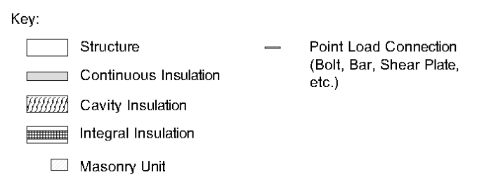
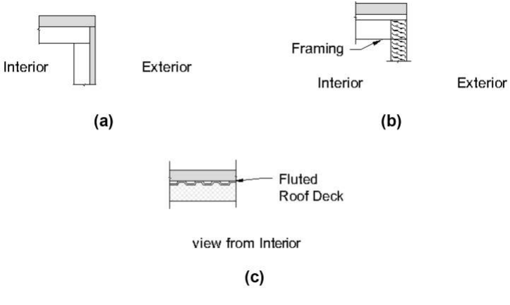
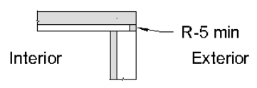
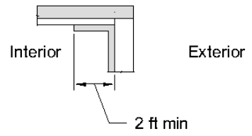
PDF Page 371
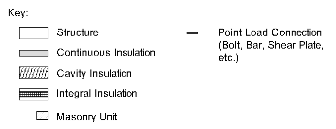
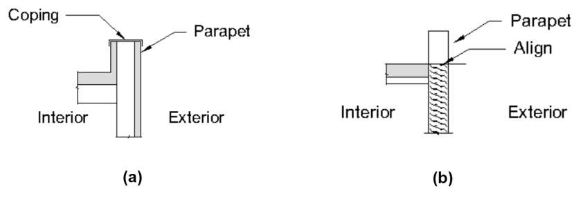
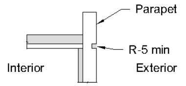
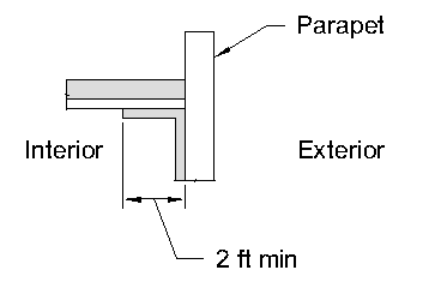
(d)
(c)
Figure K-2
a. Wall with exterior continuous insulation (Section 5.5.5.1.2[a]) b. Wall with cavity insulation (Section 5.5.5.1.2[b][1]) c. Mass wall with interior insulation (Section 5.5.5.1.2[c][1]) d. Mass wall with interior insulation (Section 5.5.5.1.2[c][2])
Figure K-3 Parapet within field of roof (Section 5.5.5.1.3).
ANSI/ASHRAE/IES Standard 90.1-2022 (I-P) 369
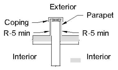
PDF Page 372
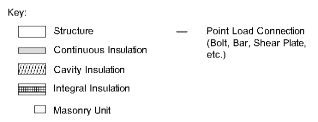
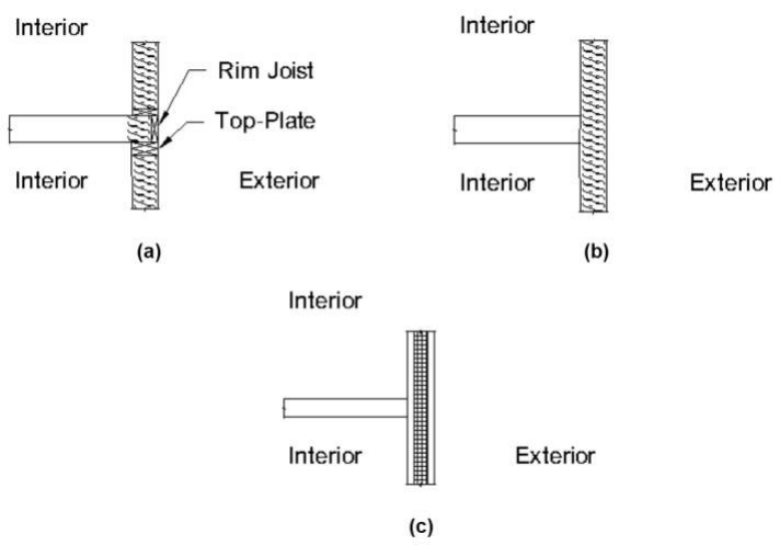
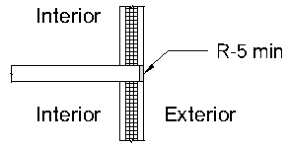
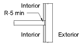
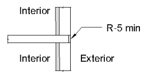
(d) (e) (f)
(g)
Figure K-4
a. Wall with cavity insulation (Section 5.5.5.2.1[b]) b. Wall with cavity insulation (Section 5.5.5.2.1[b]) c. Wall with integral insulation (Section 5.5.5.2.1[c]) d. Mass wall with integral insulation (Section 5.5.5.2.1[c]) e. Mass wall with interior insulation (Section 5.5.5.2.1[d][1]) f. Mass wall with interior insulation (Section 5.5.5.2.1[d][2]) g. Mass wall with exterior continuous insulation plus interior insulation (Section 5.5.5.2.1[e])
370 ANSI/ASHRAE/IES Standard 90.1-2022 (I-P)
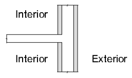
PDF Page 373
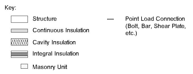
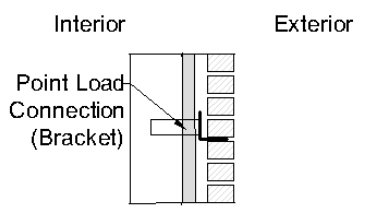
Figure K-5 Shelf angles supporting exterior cladding (Section 5.5.5.3).
(a) (b) (c)
(d)
(e)
Figure K-6
a. Fenestration and continuous insulation (Section 5.5.5.4[a]) b. Fenestration and continuous insulation (Section 5.5.5.4[a]) c. Fenestration and no continuous insulation (Section 5.5.5.4[b]) d. Insulation between fenestration and wall (Section 5.5.5.4[c], Items [1], [2], or [3]) e. Insulation between fenestration and wall (Section 5.5.5.4[c], Items [1], [2], or [3])
ANSI/ASHRAE/IES Standard 90.1-2022 (I-P) 371
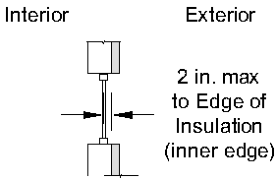
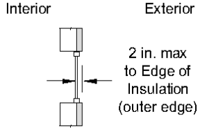
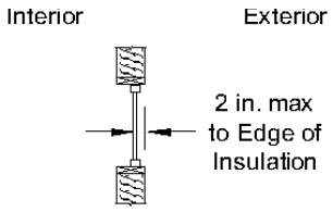
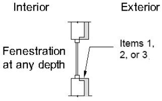
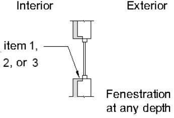
PDF Page 374
(This is a normative appendix and is part of this standard.)
NORMATIVE APPENDIX L MECHANICAL SYSTEM PERFORMANCE RATING METHOD
L1. GENERAL
L1.1 Scope. This appendix offers an alternative path of compliance for HVAC systems in accordance with Section 6.6.2. This appendix establishes the requirements for HVAC systems that use the Mechanical System Performance Rating Method and requirements for calculating TSPRp and TSPRr to demonstrate compliance in accordance with Section 6.6.2.2. Not all HVAC systems are allowed to use the Mechanical System Performance Rating Method as described in Section L1.1.1.
L1.1.1 Allowable HVAC Systems. HVAC systems are allowed to use the Mechanical System Performance Rating Method if they comply with all the following criteria:
a. The HVAC system type is included in Table L.1.1.1. b. The HVAC system serves a building use type included in Section L1.1.1.1. c. The HVAC system is not excluded by Section L1.1.1.2. d. The HVAC system is powered by grid-delivered electricity, renewable electricity, natural gas, propane,
renewable thermal energy, or distillate fuel oil.
Informative Notes:
- The intention of the scope is to allow most of the building to use the TSPR path and have portions of the buildings that cannot use the TSPR path use either the prescriptive path or the Computer Room System Path.
- The allowed system types may not be supported by all simulation program versions. The simula- tion program is required to support the reference systems for the building types modeled, and the proposed system type(s) must be supported by the simulation program .
L1.1.1.1 Allowable Building Use Types. HVAC systems that serve the following building use types are allowed to use the Mechanical System Performance Rating Method:
a. Large office ( gross conditioned floor area >150,000 ft [2] or >5 stories ) b. Medium office ( gross conditioned floor area 5000 to 150,000 ft [2] and ≤5 stories ) c. Small office ( gross conditioned floor area ≤5000 ft [2] and ≤5 stories ) d. Retail e. Multifamily (including dormitory) f. Hotel (including motel) g. School (including education and university) h. Other building use types that are <1000 ft [2] and <10% of the building conditioned floor area unless spe cifically excluded by Section L1.1.1.2(a)
Informative Note: Item (h) allows for a small sandwich or coffee counter service area but not a restaurant in an office building lobby or bookstore, for example.
L1.1.1.2 Excluded HVAC Systems. The following HVAC systems are excluded from using the Mechanical System Performance Rating Method:
a. HVAC systems serving one of the following excluded building areas:
- Data centers and computer rooms with equipment power density exceeding 20 W/ft [2] of conditioned floor area and exceeding 10 kW of equipment load
- Laboratories with fume hoods
- Locker rooms with more than four showers
- Cafeterias and dining rooms
- Restaurants and commercial kitchens with total cooking capacity greater than 100,000 Btu/h (does not include break rooms)
- Natatoriums or rooms with saunas
- Areas of buildings with commercial refrigeration equipment exceeding 100 kW of power input b. HVAC systems that are not replaced in their entirety as part of an alteration and are not serving initial
build-out construction
372 ANSI/ASHRAE/IES Standard 90.1-2022 (I-P)
PDF Page 375
| Table L.1.1.1 Method | Proposed Building HVAC Systems Allowed to Use the Mechanical System Performance Rating |
|---|---|
| System No. | System Name |
| 1 | Packaged terminal air conditioner(with electric or hydronic heat) |
| 2 | Packaged terminal heat pump |
| 3 | Packaged single-zone furnacea and/or air-cooled air conditioner (includes split systems b) |
| 4 | Packaged single-zone heat pump (air-to-air only) (includes split systems b and electric or gas supplemental heat) |
| 5 | VRF system (air source) |
| 6 | Four-pipe fan coil |
| 7 | Water-source heat pump (water loop), water-source_VRF system_, or water-source air conditioner |
| 8 | Ground-source heat pump |
| 9 | Packaged_VAV system_ (DX cooling) a |
| 10 | VAV system (hydronic cooling) a |
| 11 | VAV system with fan-powered_terminal_ units |
| 12 | DOAS (in conjunction with_systems_ 1 through 8) |
a. Reheat or primary heat may be electric, hydronic, or gas furnace. b. Condensing units with DX air handlers are modeled as package furnace with air conditioners or heat pumps. Informative Note: See Section 3.3 for a full list of terms used in this table.
c. HVAC systems serving portions of the building that are also served in parallel by other HVAC systems not
allowed to use the Mechanical System Performance Rating Method d. HVAC systems using any of the following:
- District heating or cooling
- Small-duct high-velocity air-cooled, space -constrained air-cooled, single-package vertical air condi- tioner, single-package vertical heat pump
- Double-duct air conditioner or double-duct heat pump as defined in 10CFR part 431, Subpart F
- Packaged terminal air conditioners and packaged terminal heat pumps that have cooling capacity greater than 12,000 Btu/h
- Systems with a common heating source serving both HVAC and service water heating equipment
- HVAC systems that provide recovered heat for service water heating
Exceptions to L1.1.1.2(a) and (c):
- Multiple-zone HVAC systems in Table L.1.1.1, including dedicated outdoor air systems (DOAS), where 80% or more of system supply air serves allowed building use types in accordance with Section L1.1.1.1 and 20% or less of system supply air serves excluded areas in Items (a) or (c).
- Central chiller or boiler plants where 80% or more of capacity serves allowed building use types in accordance with Section L1.1.1.1 and 20% or less of capacity serves excluded areas in items (a) or (c).
L2. MECHANICAL SYSTEM PERFORMANCE RATING METHOD
L2.1 Compliance
L2.1.1 Mandatory Requirements. All HVAC systems in the proposed building design shall comply with the requirements in Section 6.2.1.
Informative Note: Buildings using the Mechanical System Performance Rating Method are required to meet all mandatory provisions in Section 6.4 in accordance with Section 6.2.1. For example, while demand control ventilation ( DCV ) controlled area in the proposed building is one of the user entries in the simulation program, the minimum entry needs to meet the floor area where DCV is required in accordance with Section 6.4.3.8. The intent of this entry is to give credit for DCV control in more area than required, but not to allow DCV that is a mandatory requirement to be traded off with other efficiency improvements.
ANSI/ASHRAE/IES Standard 90.1-2022 (I-P) 373
PDF Page 376
L2.1.2 Mechanical System Performance Rating Method Requirements. All HVAC systems using the Mechanical System Performance Rating Method shall demonstrate compliance using TSPRp and TSPRr in accordance with Section 6.6.2 and the following requirements:
a. TSPRp and TSPRr shall be calculated in accordance with Section L2.1.5, “Calculating TSPR, ” and the
requirements of Sections L1, L3, L4, and L5. b. Alterations that include replacement of the entire HVAC system shall be modeled as a new building . c. HVAC systems shall comply with Section L2.1.4 “Partial Prescriptive Requirements.” d. Initial build-out construction shall be modeled in accordance with Section L2.1.3, “Core and Shell/Initial
Build-Out Construction Analysis.” e. Compliance documentation and supplemental information shall be submitted in accordance with Sec tions 4.2.2 and L2.1.6 “ TSPR Submittals.”
L2.1.3 Core and Shell/Initial Build-Out Construction Analysis. Where the building permit applies to only a portion of the HVAC system in a building, and the remaining components will be designed under a future building permit or were previously installed, the future or previously installed components shall be modeled as follows:
a. Where the HVAC zones that do not include HVAC systems in the current permit will be or are served by
independent systems, the block (see Section L2.2.1) including those zones shall not be included in the model. b. Where the HVAC zones that do not include complete HVAC systems in the permit are intended to receive
HVAC services from systems in the permit, their proposed zonal systems shall be modeled with equip- ment that meets but does not exceed the requirements of Sections 6.4 and 6.5. c. Where the zone equipment in the permit receives HVAC services from previously installed systems that
are not in the permit, the previously installed systems shall be modeled with equipment matching the certified value of what is installed or equipment that meets the requirements of Sections 6.4 and 6.5, whichever has the more efficient energy use. d. Where the central plant heating and cooling equipment is completely replaced and HVAC zones with
existing systems receive HVAC services from systems in the permit, their proposed zonal systems shall be modeled with equipment that meets but does not exceed the requirements of Sections 6.4 and 6.5. Informative Notes:
- Examples of HVAC systems that are intended to receive HVAC services from systems in the permit include future zonal water source heat pumps that will receive loop water that is heated by a boiler or is cooled by a cooling tower included in the permit, any system that will receive outdoor ventilation air from a DOAS included in the permit, and future zone terminal units that will be connected to a central VAV system included in the permit.
- An initial build-out with heating coils served from a previously installed system with a high_efficiency_ condensing boiler would use the installed efficiency if it exceeded the current requirements. If the installed boiler had a lower efficiency than the current requirements, the current requirement would be used.
- A partial central plant upgrade (e.g., chiller but not boiler replacement) cannot use this method.
L2.1.4 Partial Prescriptive Requirements. HVAC systems using the HVAC Performance Rating Method shall meet relevant prescriptive requirements in Section 6.5 as follows:
a. Air economizers shall meet the requirements of Sections 6.5.1.1.5 and 6.5.1.1.6. b. Steam humidifiers shall meet requirements of Section 6.5.2.4. c. Variable-air-volume systems shall meet requirements of Sections 6.5.3.2.2, 6.5.3.2.3, and 6.5.3.3. d. Hydronic systems shall meet the requirements of Section 6.5.4.2. e. Plants with multiple chillers or boiler s shall meet the requirements of Section 6.5.4.3. f. Chilled-water and heating-water supply temperature reset shall meet the requirements of Section 6.5.4.4 without exception. g. Hydronic (water loop) heat pumps and water-cooled unitary air conditioners shall meet the requirements
of Section 6.5.4.5. h. Cooling-tower turndown shall meet the requirements of Section 6.5.5.4. i. Heating of unenclosed spaces shall meet the requirements of Section 6.5.8.1. j. Hot-gas bypass shall meet the requirements of Section 6.5.9. k. Systems shall meet the door switch control requirements of Section 6.5.10. l. Refrigeration systems shall meet the requirements of Section 6.5.11.
374 ANSI/ASHRAE/IES Standard 90.1-2022 (I-P)
PDF Page 377
L2.1.5 Calculating TSPR. TSPRp shall be calculated according to Equation L-1:
TSPRr
= -------------------------------Loads r HVACinput p
(L-1)
where
Loads r = sum of the annual heating and cooling loads for the TSPR reference building design met by the building HVAC system, thousand Btu.
HVACinput p = sum of the annual HVAC energy input for heating, cooling, fans, energy recovery, pumps, and heat rejection for the proposed design . The HVAC energy input units shall be in accordance with Section L5.
TSPRr shall be calculated according to Equation L-2:
TSPRr
= -----------------------------Loads r - HVACinput r
(L-2)
where
Loads r = sum of the annual heating and cooling loads for the TSPR reference building design met by the building HVAC system, thousand Btu.
HVACinput r = sum of the annual HVAC energy input for heating, cooling, fans, energy recovery, pumps, and heat rejection for the TSPR reference building design. The HVAC energy input units shall be in accordance with Section L5.
Informative Note: The annual HVAC energy uses calculated using the Mechanical System Performance Rating Method are not predictions of whole- building energy consumption for an actual proposed building after construction . Actual experience will differ from these calculations due to variations such as occupancy, building operation and maintenance, weather, energy use of systems and building areas not covered by this procedure, changes in energy prices between design of the building and occupancy, and the precision of the calculation tool.
L2.1.6 TSPR Submittals. Where TSPRp and TSPRr are used to demonstrate compliance in accordance with Section 6.6.2, documentation shall be provided to the building official including the following:
a. A compliance report, as outlined in Section L3.4, generated by the simulation program. b. A mapping of the actual building HVAC component characteristics and those simulated in the proposed
design showing how individual pieces of HVAC equipment identified above have been combined into average inputs as required by the simulation program, including (but not limited to) the following:
- Fans
- Hydronic pumps
- Air handlers
- Packaged cooling equipment
- Furnaces
- Heat pumps
- Boiler s
- Chillers
- Heat-rejection equipment (open- and closed-circuit cooling towers; dry coolers)
- Electric resistance coils
- Condensing units
- Motors for fans and pumps
- Energy recovery devices c. For each piece of equipment identified in item (b), include the following along with the units specified in
Table L2.2.3 as applicable:
- Equipment name or tag consistent with that found on the design documents
- Rated Efficiency level, full-load efficiency as rated in Section 6.8
- Rated capacity
- Where not provided by the simulation program report in item (a), documentation of the calculation of any weighted equipment efficiencies input into the program.
ANSI/ASHRAE/IES Standard 90.1-2022 (I-P) 375
PDF Page 378
- Electrical input power for fans and pumps (before any speed or frequency control device ) at design condition and calculation of input value (W/cfm or W/gpm) d. A floor plan of the building identifying how portions of the building are assigned to the simulated blocks
(See Section L2.2.1) and which areas of the building are served by HVAC systems required to meet the requirements of Section 6.5 or Section 6.6.1.
Informative Note: The items listed under items (b) and (c) may either be included in the report generated by the simulation program or submitted separately. The compliance report required by Section L3.4 includes the composite systems entered into the program for the blocks. These may differ from actual sys- tems and may be based on capacity efficiency weighting per Section L2.2.3.1. The simulation program may allow input of individual actual systems and perform the weighting, or it may require the user to perform that weighting separately and input the weighted efficiencies . In the second case, the weighted efficiency calculation would be included under item (c) here.
L2.2 Proposed Building Information Required. The simulation of HVAC systems and the HVAC zones they serve shall be modeled based on building information required by this section.
L2.2.1 Simplified Block Approach. The geometry of buildings shall be configured using one or more simplified geometric simulation building blocks, referred to as “blocks” in this appendix. Each block contains one or multiple thermal blocks . A more complex zoning of the building shall be allowed where all thermal zones in the reference and proposed model are the same and rules related to block geometry and HVAC system assignment to blocks are met with appropriate assignment to thermal zones .
L2.2.1.1 Block Geometry. Each block shall define attributes including block dimensions, number of stories, floor-to-floor height, and floor-to-ceiling height. The simulation program is permitted to allow the use of simplified shapes (such as rectangle, L-shape, H-shape, U-shape, or T-shape) to represent blocks. Where actual building shape does not match these predefined shapes, simplifications are permitted providing the following requirements are met:
a. The gross conditioned floor area and volume of each block shall match the actual proposed design within
10%. b. The area of each exterior building envelope component from Tables 5.5-0 through 5.5-8 is accounted for
within 10% of the actual proposed design . c. The area of vertical fenestration and skylights is accounted for within 10% of the actual proposed design . d. The orientation of each component in items (b) and (c) is accounted for within 45 degrees of the actual
proposed design .
The user shall create multiple blocks , if necessary, to meet these requirements.
L2.2.1.2 Number of Blocks. One or more blocks shall be created per building based on the following restrictions:
a. Each block shall have only one building use type. At least one single block shall be created for each
unique use type, including where one HVAC system serves two different use types. b. Each block shall be served by only one type of primary or zonal HVAC system . A DOAS system shall be
permitted to serve blocks served by other systems . A single block shall be created for each unique primary or zonal HVAC system type and building use type combination. Multiple HVAC units of the same type are permitted to be represented in one block in accordance with Section L2.2.3.1. c. Each block shall have a single definition of floor-to-floor or floor-to-ceiling heights. Where story heights
differ by more than 2 ft, unique blocks shall be created for the stories with varying heights. d. Each block can include either above- grade or below- grade exterior stories . For buildings with both
above- grade and below- grade stories, separate blocks shall be created for each. For buildings with sto- ries partially above grade and partially below grade, if the total wall area of the story in consideration is greater than or equal to 50% above grade, it shall be simulated as a completely above- grade block; otherwise, it shall be simulated as a below- grade block. e. In order to combine multiple stories into a single block, each wall on a facade of a block shall have sim ilar vertical fenestration area . The product of the proposed design U-factor times the area of vertical fen- estration (UA VerFen ) on each facade of a given story cannot differ by more than 15% of the average UA VerFen for that facade in each block. The product of the proposed design solar heat gain coefficient ( SHGC ) times the area of vertical fenestration ( SHGCAVerFen ) on each facade of a given story cannot differ by more than 15% of the average SHGCAVerFen for that facade in each block. If these conditions are not met, additional blocks shall be created consisting of stories with similar fenestration .
376 ANSI/ASHRAE/IES Standard 90.1-2022 (I-P)
PDF Page 379
f. For a building model with multiple blocks, each block facade input shall provide adequate information to identify the outside boundary condition (outside, inside to adjacent block, ground contact, or adiabatic) of each facade or portion of each facade that match the actual proposed design .
Informative Note: The simulation program may automatically identify the adjacent block facade outside boundary conditions through a graphic input process.
L2.2.2 Building Envelope Components. Building envelope thermal properties used in the proposed design shall be based on the actual proposed design using documented user-defined values and shall comply with all of the following:
a. Where different roof thermal properties are present in a single block, an area-weighted U-factor shall be
used. b. Where different wall constructions exist on the facade of a block, an area-weighted U-factor shall be used. c. Where different below-grade wall constructions exist in a block, an area-weighted C- factor shall be used. d. Where different floor constructions exist in the block , an area-weighted U-factor shall be used. e. Where different slab-on-grade floor constructions exist in a block, an area-weighted F-factor shall be used. f. Where different vertical fenestration types or sill heights exist, area-weighted sill heights, U-factor, and SHGC values shall be used. g. Where different skylight types exist, area-weighted U-factor and SHGC values shall be used. h. Permanent shading devices such as overhangs shall be modeled only if >50% of the area of vertical fen-
estration on a facade is shaded by the same.
L2.2.3 HVAC System Components. The HVAC system parameters shall be provided for the proposed design at design conditions unless otherwise stated with clarifications and simplifications as described in Table L2.2.3 and as follows:
a. All HVAC zones within a block shall be served by the same HVAC system type as listed in Table L.1.1.1. b. Where multiple system components serve a block, average values weighted by the appropriate metric as
described in Section L2.2.3.1 shall be used. c. The Table L2.2.3 parameter requirements are based on input of full-load. equipment efficiencies with
adjustment using part-load curves integrated in the simulation program . Where other approaches to partload adjustment are used, it is permitted for specific input parameters to vary.
Informative Note: Table L2.2.3 includes both user-defined parameters and parameters that are fixed in the simulation program and may not be changed by the user. They are maintained in one table here so related items can be viewed together in context.
L2.2.3.1 Proposed Building HVAC System Aggregation. Projects using the Mechanical System Performance Rating Method shall comply with all the following requirements.
a. Where multiple fan systems serve a single block, fan power shall be based on weighted average using the
design supply air (cfm). b. Where multiple cooling systems serve a single block, COP shall be based on a weighted average using
cooling capacity. DX coils shall be entered as multistage if more than 50% of coil capacity serving the block is multistage with staged controls. c. Where multiple heating systems serve a single block, thermal efficiency or heating COP shall be based
on a weighted average using heating capacity. d. Where multiple boiler s or chillers serve a heating-water or chilled-water loop, efficiency shall be based
on a weighted average for using heating or cooling capacity. e. When multiple cooling towers serving a condenser water loop are combined, the cooling tower effi-
ciency, cooling tower design approach, and design range are based on a weighted average of the design water flow rate through each cooling tower. f. Where multiple pumps serve a heating-water, chilled-water, or condenser water loop, pump power shall be based on a weighted average for using design water flow rate. g. When multiple system types with and without economizers are combined, the economizer maximum out-
door air fraction of the combined system shall be based on weighted average of 100% supply air for sys- tems with economizers and design outdoor air for systems without economizers. h. Multiple systems with and without ERVs cannot be combined. i. Systems with and without supply air temperature reset cannot be combined. j. Systems with different fan control (constant volume, multispeed, or VAV ) for supply fans cannot be combined.
ANSI/ASHRAE/IES Standard 90.1-2022 (I-P) 377
PDF Page 380
L3. SIMULATION PROGRAM
The simulation program shall have the following capabilities:
Table L2.2.3 Proposed Building HVAC System Parameters
| Category | Parameter | Fixed or User Defined | Required | Applicable Systems a |
|---|---|---|---|---|
| HVAC System Type | System type | User defined | Selected from Table L.1.1.1 | All |
| System Sizing | Design-day information | Fixed | 99.6% heating design and 1% dry-bulb and 1% wet-bulb cooling design | All |
| System Sizing | Zone coil capacity | Fixed | Sizing factors used are 1.25 for heating_equipment_ and 1.15 for cooling_equipment._ | All |
| System Sizing | Supply airflow | Fixed | Based on the greater of a supply-air-to-room-air temperature_set point_difference of 20°F or required_OA_ ventilation | |
| Outdoor Ventilation Air and Filtration | Portion of supply air with proposed filter ≥MERV 13 | User defined | Percentage of supply airflow subject to higher filtration (adjusts reference fan power higher; prorated) | All |
| Outdoor Ventilation Air and Filtration | Outdoor_ventilation_ supply airflow rate adjustments | Fixed | Basis is 1.0 zone air distribution effectiveness | All |
| Outdoor Ventilation Air and Filtration | Outdoor_ventilation_ supply airflow rate | Fixed | As specified in ASHRAE/IES Standard 90.1 Normative Appendix C, adjusted for proposed_DCV_ control (See “Demand Control Ventilation” category below.) | All |
| System Operation | Space temperature_set points_ | Fixed | As specified in ASHRAE/IES Standard 90.1 Normative Appendix C, except for hotel/motel, which shall be 70°F heating 72°F cooling | All |
| System Operation | Fan operation—occupied (where DOAS meets ventilation requirements) | User defined | Fan either runs continuously during occupied hours or is cycled to meet thermal load. | All (continuous) 1–11 (cycles) |
| System Operation | Fan operation—occupied (where heating and cooling units provide_ventilation_—no DOAS) | Fixed | Fan runs continuously during occupied hours;VAV or multispeed fans reduce airflow related to thermal load. | 1–11 |
| System Operation | Fan operation—night cycle | Fixed | Fan cyclesON to meet_setback_ temperatures. | 1–11 |
| Packaged Equipment Efficiency | DX cooling_efficiency_ | User defined | Cooling_COP_ without fan_energy_ calculated in accordance with Section L4.2.3(d) | 1, 2, 3, 4, 5, 7, 8, 9, 11, 12 |
| Packaged Equipment Efficiency | DX coil number of stages | User defined | Single stage or multistage | 3, 4, 9, 10, 11, 12 |
| Packaged Equipment Efficiency | Heat-pump_efficiency_ | User defined | Heating_COP_ without fan_energy_ calculated in accordance with Section L4.2.3(d) | 2, 4, 5, 7, 8, 12 |
| Packaged Equipment Efficiency | Furnace_efficiency_ | User defined | Furnace thermal_efficiency_ | 1, 3, 9, 12 |
| Heat-Pump Supplemental Heat | Heat source | User defined | Electric resistance or gas furnace | 2, 4, 7, 8, 12 |
| Heat-Pump Supplemental Heat | Control | Fixed | Electric heat locked out above 40°F OAT. Runs as needed in conjunction with compressor between 40°F and 0°F. Gas heat operates in place of the heat pump when the heat pump cannot meet load. | 2, 4, 7, 8, 12 |
a. Applicable systems from Table L.1.1.1 Informative Note: See Section 3.3 for a full list of terms used in this table.
PDF Page 381
Table L2.2.3 Proposed Building HVAC System Parameters (Continued)
| Category | Parameter | Fixed or User Defined | Required | Applicable Systems a |
|---|---|---|---|---|
| System Fan Power and Controls | Design fan power, W/cfm | User defined | Input electric power for all fans required to operate at_fan system design conditions_ divided by the supply airflow rate. Include any VSD losses at design condition. This is a wire-to-air value, including all drive, motor_efficiency_, and other losses. | All |
| System Fan Power and Controls | Part-load fan controls: • Constant volume • Two-speed or three-speed, then input: • W/cfm at each speed • % cfm at leach speed • VAV | User defined | Static pressure_reset_ included for_VAV_ | All (constant volume, two speed) 9, 10, 11 (VAV) |
| Variable-Air- Volume Systems | SAT controls (select): • None • OAT SAT_reset_ • Warmest zone SAT_reset_ | User defined | If not SAT_reset_, then constant at 55°F. Options for_reset_ based on OAT or warmest zone. If OAT_reset_, SAT is_reset_ higher to 60°F at outdoor low of 50°F. SAT is 55°F at outdoor high of 70°F. If warmest zone, then the user can specify the minimum and maximum temperatures. | 9, 10, 11 |
| Variable-Air- Volume Systems | • Zone minimum damper and_Evs_ • Standard 62.1 simple method except for schools | Fixed | • Schools: 1.2 ×Voz zone minimum design_ventilation_ rate, cfm;Evs = 0.65 • Other_buildings_: Simple Standard 62.1 method is 1.5 ×Voz zone minimum design ventilation rate, cfm;Evs = 0.75. | 9, 10, 11 |
| Variable-Air- Volume Systems | Dual_set point_ minimum_VAV_ damper position | User defined | Heating minimum and maximum airflow fraction | 9, 10, 11 |
| Variable-Air- Volume Systems | Terminal-unit heating source | User defined | Electric or hydronic | |
| Variable-Air- Volume Systems | FPTU type | User defined | Series or parallel FPTU | 11 |
| Variable-Air- Volume Systems | Parallel FPTU fan | Sized for 50% peak primary air at 0.35 W/cfm | 11 | |
| Variable-Air- Volume Systems | Series FPTU fan | Fixed | Sized for 50% peak primary air at 0.35 W/cfm | 11 |
| Economizer | OSA economizer presence | User defined | Yes or no | 3, 4, 5, 6, 9, 10, 11 |
| Economizer | Economizer high limit | Fixed | • Lockout on differential dry-bulb temperature (OAT > RAT) in Climate Zones 6A, 5A, All B, and C • Fixed enthalpy > 28 Btu/lb or fixed dry-bulb OAT > 75°F in Climate Zones 0A to 4A | |
| Energy Recovery | Sensible effectiveness | User defined | Heat exchanger sensible effectiveness at design heating and cooling conditions | 3, 4, 9, 10, 11, 12 |
| Energy Recovery | Latent effectiveness | User defined | Heat exchanger latent effectiveness at design heating and cooling conditions | 3, 4, 9, 10, 11, 12 |
| Energy Recovery | Bypass SAT_set point_ | User defined | If bypass, target supply air temperature | 3, 4, 9, 10, 11, 12 |
| Energy Recovery | Fan power reduction when in bypass | User defined | If bypass, specify fan power reduction, W/cfm. | 3, 4, 9, 10, 11, 12 |
a. Applicable systems from Table L.1.1.1 Informative Note: See Section 3.3 for a full list of terms used in this table.
PDF Page 382
Table L2.2.3 Proposed Building HVAC System Parameters (Continued)
| Category | Parameter | Fixed or User Defined | Required | Applicable Systems a |
|---|---|---|---|---|
| Demand Control Ventilation | DCV applicationON/OFF | User defined | Percentage of block floor area under occupied standby controls,ON/OFF only (see Section 6.5.3.8) with no variable control | 3, 4, 9, 10, 11, 12 |
| Demand Control Ventilation | DCV application CO2 | User defined | Percentage of block_floor_ area under variable_DCV_ control (CO2); may include both variable andON/OFF control | 3, 4, 9, 10, 11, 12 |
| Dedicated Outdoor Air System | DOAS fan power, W/cfm | User defined | Fan electrical input power in W/cfm of supply airflow | 12 |
| Dedicated Outdoor Air System | DOAS supplemental heating and cooling | User defined | Heating source, cooling source,energy recovery, and respective_efficiencies_ | 12 |
| Dedicated Outdoor Air System | Maximum SAT_set point_ (cooling) | User defined | SAT_set point_ if DOAS includes supplemental cooling | 12 |
| Dedicated Outdoor Air System | Minimum SAT_set point_ (heating) | User defined | SAT_set point_ if DOAS includes supplemental heating | 12 |
| Heating Plant | Boiler efficiency | User defined | Boiler thermal_efficiency_ | 1, 6, 7, 9, 10, 11, 12 |
| Heating Plant | HW loop configuration | User defined | Variable-flow primary only; variable-flow primary and secondary; constant-flow primary and variable-flow secondary | 1, 6, 7, 9, 10, 11, 12 |
| Heating Plant | HW primary_pump_ power, W/gpm | User defined | HW constant primary_pump_ input W/gpm HW flow | 1, 6, 7, 9, 10, 11, 12 |
| Heating Plant | HW secondary_pump_ power, W/gpm | User defined | HW variable secondary_pump_ input W/gpm HW flow (if primary/secondary) | 1, 6, 7, 9, 10, 11, 12 |
| Heating Plant | HW loop temperature | User defined | HW supply and return temperatures, °F | 1, 6, 7, 9, 10, 11, 12 |
| Heating Plant | HW temperature_reset_ included | User defined | Yes/no | 1, 6, 7, 9, 10, 11, 12 |
| Heating Plant | HWST_reset_ | Fixed | Reset HWST by 27.3% of design temperature difference (HWST – 70°F_space_ heating temperature_set point_) between 20°F and 50°F OAT | 1, 6, 7, 9, 10, 11, 12 |
| Heating Plant | Boiler type | Fixed | Regular where input thermal_efficiency_ is less than 86%; condensing_boiler_ otherwise | 1, 6, 7, 9, 10, 11, 12 |
| Chilled-Water Plant | Chiller condenser type | User defined | Air-cooled or water-cooled; for water-cooled, positive displacement or centrifugal | 6, 10, 11, 12 |
| Chilled-Water Plant | Chiller full-load_efficiency_ | User defined | Chiller_COP_ | 6, 10, 11, 12 |
| Chilled-Water Plant | Number of chillers | User defined | In simulation, chillers will be sized equally with 1–3 chillers. | 6, 10, 11, 12 |
| Chilled-Water Plant | CHW coil design temperature difference, °F | User defined | CHWST and CHW return temperature at_design conditions_ | 6, 10, 11, 12 |
| Chilled-Water Plant | CHW loop configuration | User defined | Variable-flow primary only; variable-flow primary and secondary; constant-flow primary and variable-flow secondary | 6, 10, 11, 12 |
| Chilled-Water Plant | CHW primary_pump_ power, W/gpm | User defined | Primary_pump_ input, W/gpm; CHW flow | 6, 10, 11, 12 |
| Chilled-Water Plant | CHW secondary_pump_ power, W/gpm | User defined | Secondary_pump_ input, W/gpm; CHW flow (if primary/secondary) | 6, 10, 11, 12 |
| Chilled-Water Plant | CHW temperature_reset_ included | User defined | Yes/no | 6, 10, 11, 12 |
| Chilled-Water Plant | CHW temperature_reset_ schedule | Fixed | OA reset: Use input CHWST at 80°F_outdoor air_ dry-bulb and above and CHWST 10°F at 60°F_OA_ dry-bulb and below, ramped linearly between | 6, 10, 11, 12 |
a. Applicable systems from Table L.1.1.1 Informative Note: See Section 3.3 for a full list of terms used in this table.
PDF Page 383
Table L2.2.3 Proposed Building HVAC System Parameters (Continued)
| Category | Parameter | Fixed or User Defined | Required | Applicable Systems a |
|---|---|---|---|---|
| Condenser Loop | Condenser water-pump power, W/gpm | User defined | Pump input, W/gpm; condenser water flow | 6, 7, 8, 10, 11, 12 |
| Condenser Loop | Condenser water-pump control | Fixed | Constant-speed, one_pump_ per chiller | 6, 7, 8, 10, 11, 12 |
| Heat Rejection | Heat-rejection_equipment efficiency_ | User defined | gpm/hp at_design conditions_, where hp is the sum of nameplate fan and integral spray_pump_ motor hp, if applicable | 6, 7, 8, 10, 11, 12 |
| Heat Rejection | Open-circuit cooling tower flow turndown | Fixed | Flow turndown per Section 6.5.5.4 | 6, 7, 8, 10, 11, 12 |
| Heat Rejection | Heat-rejection fan control | User defined | Constant or variable speed | 6, 7, 8, 10, 11, 12 |
| Heat Rejection | Heat-rejection approach and range | User defined | Design heat-rejection approach and range temperature | 6, 7, 8, 10, 11, 12 |
| Heat-Pump Loop | Loop flow and heat-pump control valve | Fixed | Two-position valve with VSD on_pump_ | 7, 8 |
| Heat-Pump Loop | Heat-pump loop flow control | Fixed | Loop flow at 3 gpm/ton | 7, 8 |
| Heat-Pump Loop | Heat-pump loop minimum and maximum temperature control | User defined | User input; restrict to minimum 20°F and maximum 40°F temperature difference. | 7, 8 |
| Ground-Loop Heat-Pump Bore Field | Fixed | Bore depth = 250 ft; bore length 200 ft/ton for greater of cooling or heating load | 8 | |
| Ground-Loop Heat-Pump Bore Field | Fixed | Bore spacing = 15 ft | Bore spacing = 15 ft | |
| Ground-Loop Heat-Pump Bore Field | Fixed | Bore diameter = 5 in. with 3/4 in. nominal diameter polyethylene pipe | Bore diameter = 5 in. with 3/4 in. nominal diameter polyethylene pipe | |
| Ground-Loop Heat-Pump Bore Field | Fixed | Ground and grout conductivity = 4.8 Btu·in./h·ft2·°F | Ground and grout conductivity = 4.8 Btu·in./h·ft2·°F |
a. Applicable systems from Table L.1.1.1 Informative Note: See Section 3.3 for a full list of terms used in this table.
PDF Page 384
L3.1 Calculation of the TSPR. The simulation program shall calculate both the TSPRp and TSPRr based only on the input for the proposed design and the requirements of this appendix. The calculation procedure shall not allow the user to directly modify either the building component characteristics of the TSPR refer- ence building design or the HVAC parameters identified as fixed input in Table L2.2.3.
L3.2 TSPR Simulation Program. All components of the proposed design for blocks served by HVAC sys- tems using this method shall be explicitly modeled by the simulation program . The code official shall be permitted to approve a simulation program for a specified application or limited scope.
L3.2.1 Minimum Capability. The simulation program shall be approved by the code official and shall, at a minimum, have the ability to explicitly model all of the following:
a. 8760 hours per year b. Hourly variations in occupancy, lighting power, miscellaneous equipment power, thermostat set points,
and HVAC system operation, defined separately for each day of the week and holidays c. Thermal mass effects d. Ten or more thermal blocks e. Part-load performance curves or other part-load adjustment methods for mechanical equipment f. Capacity and efficiency correction curves or other part-load adjustment methods for mechanical heating and mechanical cooling equipment g. Air economizers with integrated controls h. The energy use of all HVAC system types included in the analysis and energy impact from all related
fixed and user inputs in Table L2.2.3 i. Ability to automatically generate the TSPR reference building design as specified in Section L4.3
Informative Note: The simulation program shall include clear prompts or accessible help-topic references defining specific parameters and units for all required building and system characteristic inputs.
L3.2.2 TSPR Determination. The simulation program shall have the ability to either directly determine the TSPRp and TSPRr or produce hourly and annual reports of energy use by each energy source suitable for determining the TSPRp and TSPRr using a separate calculation.
L3.2.3 Load Calculations. The simulation program shall be capable of performing design load calculations to determine required HVAC equipment capacities and air and water flow rates in accordance with Section 6.4.2.1 for both the proposed design and TSPR reference building design .
L3.2.4 Testing
L3.2.4.1 The simulation program shall be tested according to ASHRAE Standard 140, except for Sections 7 and 8 of Standard 140. The required tests shall include building thermal envelope and fabric load tests (Sections 5.2.1, 5.2.2, and 5.2.3), ground coupled slab-on- grade analytical verification tests (Section 5.2.4), space -cooling equipment performance tests (Section 5.3), space -heating equipment performance tests (Section 5.4), and air-side HVAC equipment analytical verification tests (Section 5.5) along with the associated reporting (Section 6).
L3.2.4.2 The test results and modeler reports shall be posted on a publicly available website and shall include the test results of the simulation program and input files used for generating the results along with the results of the other simulation programs included in ASHRAE Standard 140, Annexes B8 and B16. The modeler report in Standard 140, Annex A2, Attachment A2.7 shall be completed for results exceeding the maximum or falling below the minimum of the reference values and for omitted results.
Informative Notes:
- There are no pass/fail criteria established by this testing requirement.
- Based on the Section 3.2 definition, simulation program includes the simulation engine and the corresponding user interface. The testing of a simulation program only meets the requirements of Section L1 for that simulation program and cannot be used as proxy for documenting compliance of another simulation program that uses the same simulation engine.
L3.3 Climatic Data. Climatic data shall meet the requirements of Section G2.3.
L3.4 Compliance Report. The simulation program shall generate a report that includes the following:
a. Address of the building b. Name of individual completing the compliance report c. Name and version of the compliance simulation program, the edition of Standard 90.1 the simulation
program method complies with, and the link to the website that contains the ASHRAE Standard 140 testing results for the version used in accordance with Section L3.2.4 d. The dimensions, story heights, and number of stories for each block
382 ANSI/ASHRAE/IES Standard 90.1-2022 (I-P)
PDF Page 385
e. By block, the U-factor, C-factor, or F-factor for each simulated opaque building envelope component
and the U-factor and SHGC for each fenestration component f. By block or by surface for each block, the fenestration area and total area of each opaque building enve- lope component g. By block, a list of the HVAC equipment simulated in the proposed design, including the equipment type,
fuel type, rated equipment efficiencies, rated capacities, and system control parameters h. Annual site HVAC energy use by end use and energy type for the proposed design and TSPR reference
building design i. Annual sum of hourly heating and cooling loads for the TSPR reference building design j. The HVAC total system performance ratio for both the TSPR reference building design and the proposed design and compliance result in accordance with Section 6.6.2.2
Informative Note: The simulation program, at a minimum, will report compliance with the TSPR based on the compliance criteria in Section 6.6.2.2. Should a jurisdiction adopt other compliance criteria, then a separate calculation of TSPR using the reference building design and proposed design HVAC energy type input may be necessary.
L4. CALCULATION PROCEDURE
Except as specified by this appendix, the TSPR reference building design and proposed design shall be configured and analyzed using identical methods and techniques.
L4.1 Simulation of the Proposed Design (Non-HVAC). The proposed design non- HVAC systems shall be configured and analyzed as specified in this section. At a minimum, the simulation program shall support the building use types included in the analysis. The allowed building use types are listed in Section L1.1.1.1.
L4.1.1 Simplified Block Approach. The simulation program shall model the building using one or more simplified geometric simulation building blocks, described in Section L2.1. Each block contains one or multiple thermal blocks . The simulation program shall provide for simplified input described in Section L2.2 and allow for multiple block simulation.
L4.1.2 Thermal Zoning. Each story in a block shall be modeled as a single thermal block or as five ther- mal blocks consisting of four perimeter zones and a core zone. Below- grade stories shall always be modeled as a single block. If any facade in the block is less than 45 ft in length, there shall only be a single thermal block per story . Otherwise, each story shall be modeled with five thermal blocks . A perimeter zone shall be created extending from each facade to a default depth of 15 ft with a user input range of 8 to 20 ft. Where facades intersect, the zone boundary shall be formed by a 45 degree angle with the two facades. The remaining area or each story shall be modeled as a core zone with no exterior walls .
L4.1.3 Building Use Type. The building use type for each block shall be consistent with the proposed design and allowed building use types in Section L1.1.1.1. The occupant density, heat gain, and schedule shall be as specified by Normative Appendix C.
L4.1.4 Building Envelope Components. Building envelope thermal properties used in the proposed design shall be modeled based on the actual proposed design using inputs described in Section L2.2.2 and shall comply with all of the following:
a. Roofs shall be modeled with insulation above a steel roof deck. Roof solar absorptance shall be modeled
at 0.70 and thermal emittance at 0.90. b. Above-grade walls shall be modeled as steel-frame construction. c. Above- grade exterior floors shall be modeled as steel-frame construction. d. The area, U-factor, and SHGC of vertical fenestration shall be modeled for each facade based on the
actual proposed design . The simulation program shall model a combined single window centered on each facade based on the area and sill height input by the user. e. The skylight area shall be modeled for each roof based on the actual proposed design . Skylights shall be
combined into a single skylight centered on the roof of each zone based on the area input by the user.
L4.1.5 Lighting. For each block, the interior lighting power density shall be equal to the applicable allowance in Table 9.5.1 based on the assigned building use type. The lighting profile schedule shall be for the applicable building use type as specified by Normative Appendix C. The impact of lighting controls is assumed to be captured by the lighting schedule, and no explicit controls (including daylight responsive controls) shall be modeled. Exterior lighting shall not be modeled.
L4.1.6 Miscellaneous Equipment. The miscellaneous equipment schedule and power shall be based on the assigned building use type as specified by Normative Appendix C. The impact of miscellaneous equip- ment controls is assumed to be captured by the equipment schedule, and no explicit controls shall be modeled.
ANSI/ASHRAE/IES Standard 90.1-2022 (I-P) 383
PDF Page 386
Table L4.2.3-1 Fan and Pump Power Curve Coefficients
| Equation Term | Fan Power Coefficients | Col3 | Pump Power Coefficients | Col5 |
|---|---|---|---|---|
| Equation Term | VSD (no Static Pressure Reset) | VSD + Static Pressure Reset | Ride Pump Curve | VSD + Differential Pressure/Valve Reset |
| b | 0.0013 | 0.0408 | 0 | 0 |
| x | 0.147 | 0.088 | 3.2485 | 0.0205 |
| _x_2 | 0.9506 | –0.0729 | –4.7443 | 0.4101 |
| _x_3 | –0.0998 | 0.9437 | 2.5295 | 0.5753 |
Figure L4.2.3-1 Fan and pump power performance as a function of design water flow or airflow.
L4.1.7 Elevators. Elevators shall not be modeled. L4.1.8 Service Water-Heating Equipment. Service water heating shall not be modeled. L4.1.9 On-site Renewable Energy Systems. On-site renewable energy systems shall not be modeled.
L4.2 Simulation of the Proposed Design (HVAC). The proposed design HVAC systems shall be configured and analyzed as specified in this section.
L4.2.1 HVAC Equipment. The simulation program shall analyze the control parameters that meet the mandatory requirements of Section 6.4 and the parameters provided by the user or specified as fixed in Section L2.2.3 as applicable for each HVAC system included in the proposed design .
L4.2.2 Supported HVAC Systems. The HVAC systems included in the proposed design and the TSPR reference building design shall be supported by the simulation program . HVAC systems permitted are limited to those shown in Table L.1.1.1. The simulation program shall support multiple blocks being served by one central system .
L4.2.3 Proposed Building HVAC System Simulation. The HVAC systems shall be modeled as in the proposed design with clarifications and simplifications as described in Table L2.2.3 and the following rules:
a. System parameters not described in Table L2.2.3 and the following sections shall be simulated to meet
the minimum requirements of Section 6.4. b. Where multiple system components serve a block, average values weighed by the appropriate metric as
described in Section L2.2.3.1 shall be used. c. Heat loss from ducts and pipes shall not be modeled. d. The simulation program shall model part-load HVAC equipment performance using either
- full-load efficiency (adjusted for fan power input that is modeled separately) and typical part-load performance adjustments for the proposed equipment ;
- part-load adjustments based on input of both full-load and part-load metrics, or
- equipment -specific adjustments based on performance data provided by the equipment manufacturer for the proposed equipment .
384 ANSI/ASHRAE/IES Standard 90.1-2022 (I-P)
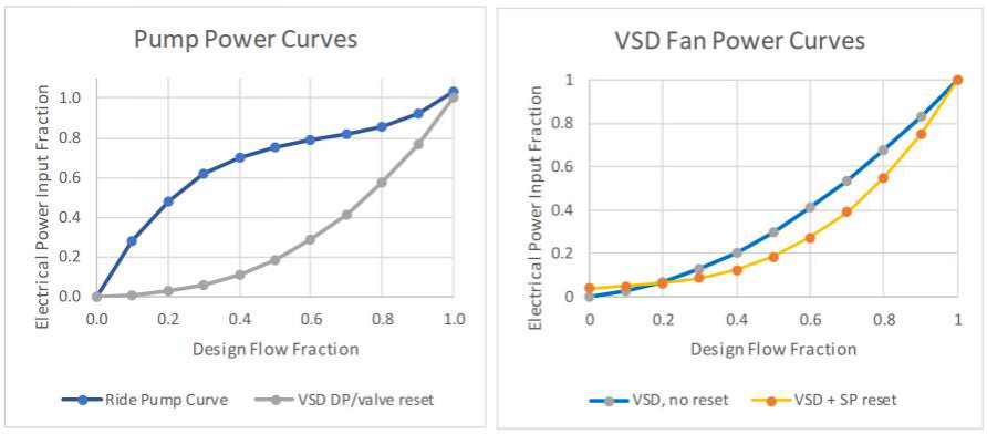
PDF Page 387
Table L4.2.3-2 DCV Outdoor Air Reduction Curve Coefficients
| Equation Term | DCV OA Reduction (y) as a Function of DCV Effective Controlled Floor Area (x) | Col3 | Col4 | Col5 |
|---|---|---|---|---|
| Equation Term | Office | School | Hotel, Motel, Multifamily, Dormitory | Retail |
| b | 0 | 0 | 0 | 0 |
| x | 0.4053 | 0.2676 | 0.5882 | 0.4623 |
| _x_2 | –0.8489 | 0.7753 | –1.0712 | –0.848 |
| _x_3 | 1.0092 | –1.5165 | 1.3565 | 1.1925 |
| _x_4 | –0.4168 | 0.7136 | –0.6379 | –0.5895 |
Figure L4.2.3-2 DCV OA reduction as a function of controlled floor area.
e. Part-load variable-speed fan and pump power shall be calculated using a cubic function with coefficients
as shown in Table L4.2.3-1. The independent variable shall be the fraction of design water flow rate for pumps and the fraction of design airflow rate for fans as shown in Figure L4.2.3-1. f. Demand control ventilation shall be modeled using a simplified approach that adjusts the design outdoor supply airflow rate based on the area of the building that is covered by DCV with coefficients as shown in Table L4.2.3-2. The input shall accommodate two types of DCV :
- Variable control based on people sensor response (CO2 sensor or other)
- ON/OFF occupied standby control that closes the VAV box primary air damper or shuts off outdoor air when the zone is completely unoccupied based on an occupancy sensor (See Section 6.5.3.8.) (Informative Note: Due to lower probability occurrence, the ON/OFF controls are given 1/3 the reduction of the CO2 sensor DCV . The outdoor air reduction factor shall be based on a smaller area of control being applied to higher density spaces first, adjusted for building type, with outdoor air reduction factors and an application formula as shown.)
For office, school, and retail:
DCV Effective Controlled Floor Area = Area VarDCV + 1/3 × Area ON-OFF AND Area ON-OFF < 1 – Area VarDCV For hotel, motel, dormitory, and multifamily:
DCV Effective Controlled Floor Area = Area VarDCV + Area ON-OFF where
ANSI/ASHRAE/IES Standard 90.1-2022 (I-P) 385
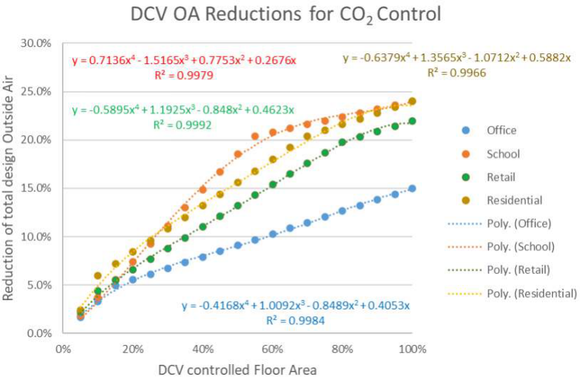
PDF Page 388
Area VarDCV = fraction of block floor area with variable sensor-based DCV control Area ON-OFF = fraction of block floor area with only occupied standby control as defined in Section 6.5.3.8 that does not also have variable sensor-based demand control ventilation .
L4.3 Simulation of the TSPR Reference Building Design. The TSPR reference building design shall be configured and analyzed as specified in this section.
L4.3.1 Non-HVAC Inputs. Utility rates, blocks, HVAC zones, building use types, schedules, occupant density, heat gains, building envelope components, lighting power, and miscellaneous equipment loads shall be modeled the same as in the proposed design.
Elevators, service water-heating equipment, and on-site renewable energy systems shall not be modeled; same as in the proposed design .
L4.3.2 HVAC Equipment. The TSPR reference building design HVAC equipment consists of separate space conditioning systems and DOASs as described in Tables L4.3.2-1 through L4.3.2-3 for the appropriate building use types. Variable-speed drive fan and pump power shall be modeled using parameters in Tables L4.3.2-1. HVAC equipment shall be modeled at minimum efficiency based on specified efficiency metrics in Tables L4.3.2-1 through L4.3.2-3. Where available in Normative Appendix G, equipment -type-specific partload performance adjustments shall be used; otherwise, typical part-load performance adjustments shall be used.
L5. TSPR METRIC FOR SITE HVAC ENERGY INPUT
For purposes of calculating TSPR for the proposed design and the TSPR reference building design, the calculated HVAC energy input of each building project energy source shall be converted to cost using the energy cost prices from Table L5-1.
Informative Notes:
-
The blended heating prices in Table L5-1 that are used for fossil fuels are not intended to represent actual average prices, but to represent a consistent blended price per 1000 Btu used. This will avoid requiring the simulation program to run the reference systems with a fossil fuels type that matches the proposed building . The common price per site fuel Btu allows proposed system effi- ciency to be properly compared with the reference system .
-
Informative Tables L5-2 through L5-5 include values for alternate energy input metrics that may be adopted by a jurisdiction. If so, the jurisdiction should replace the TSPR energy input of energy cost in Section L5 with the alternate metric and should include appropriate metric values from Informative Table L5-2 into Table L5-1. The jurisdiction should replace the MPF values in Table 6.6.2.2 with one of the following:
- For carbon emissions, replace Table 6.6.2.2 MPF values with those in Informative Table L5-3.
This table allows users to compare the quantity of carbon dioxide emissions generated by the proposed design building to the target building . For compliance purposes, it is intended for use in voluntary standards and in jurisdictions where the use of a carbon emissions metric is not preempted by U.S. federal law.
        - For source _energy_, replace Table 6.6.2.2 MPF values with those in Informative Table L5-4.

        - For _site_ _energy_, replace Table 6.6.2.2 MPF values with those in Informative Table L5-5.
386 ANSI/ASHRAE/IES Standard 90.1-2022 (I-P)
PDF Page 389
Table L4.3.2-1 TSPR Reference Building Design HVAC Complex Systems
| Building Type Parameter | Large Office (warm) a | Large Office (cold) b | School (warm) a | School (cold) b |
|---|---|---|---|---|
| System type | VAV/reheat water-cooled chiller/ electric_reheat_ with parallel fan powered boxes | VAV/reheat water-cooled chiller/ gas_boiler_ | VAV/reheat water-cooled chiller/ electric_reheat_ with parallel fan powered boxes | VAV/reheat water-cooled chiller/ gas_boiler_ |
| Fan control | VSD, no static pressure_reset_ | VSD, no static pressure_reset_ | VSD, no static pressure_reset_ | VSD, no static pressure_reset_ |
| Main fan power (W/cfm) proposed ≥MERV13 | 1.165 | 1.165 | 1.165 | 1.165 |
| Main fan power (W/cfm) proposed <MERV13 | 1.066 | 1.066 | 1.066 | 1.066 |
| Zonal fan power, W/cfm | 0.35 | NA | 0.35 | NA |
| Minimum zone airflow fraction | 1.5 ×Voz | 1.5 ×Voz | 1.2 ×Voz | 1.2 ×Voz |
| Heat/cool sizing factor | 1.25/1.15 | 1.25/1.15 | 1.25/1.15 | 1.25/1.15 |
| Outdoor air economizer | No | Yes except 4A | No | Yes except 4A |
| Occupied_outdoor air_ (= proposed) | Sum(Voz)/0.75 | Sum(Voz)/0.75 | Sum(Voz)/0.65 | Sum(Voz)/0.65 |
| Energy recovery ventilator_enthalpy recovery_ ratio bypass; SAT set point | NA | NA | 50%; no bypass | 50%; 60°F except no bypass required in Climate Zone 4A |
| Demand control ventilation | No | No | No | No |
| Cooling source | 2 water-cooled centrif. chillers | 2 water-cooled centrif. chillers | 2 water-cooled screw chillers | 2 water-cooled screw chillers |
| Cooling_efficiency_ | Table G3.5.3 | Table G3.5.3 | Table G3.5.3 | Table G3.5.3 |
| Heating source (reheat) | Electric resistance | Gas_boiler_ | Electric resistance | Gas_boiler_ |
| Furnace or_boiler_ efficiency | 1.0 | 75%Et | 1.0 | 80%Et |
| Condenser heat rejection | Axial-fan open-circuit cooling tower | Axial-fan open-circuit cooling tower | Axial-fan open-circuit cooling tower | Axial-fan open-circuit cooling tower |
| Cooling-tower_efficiency_, gpm/hp (See Section G3.2.3.11) | 38.2 | 38.2 | 38.2 | 38.2 |
| Open-circuit cooling-tower turndown (>300 ton) | 50% | 50% | 50% | 50% |
| Pump (constant flow/variable flow) | Constant flow; 10°F range | Constant flow; 10°F range | Constant flow; 10°F range | Constant flow; 10°F range |
| Open-circuit cooling-tower approach | G3.1.3.11 | G3.1.3.11 | G3.1.3.11 | G3.1.3.11 |
| Cooling condenser_pump_ power, W/gpm | 19 | 19 | 19 | 19 |
a. “Warm” refers to Climate Zones 0 through 2 and 3A. b. “Cold” refers to Climate Zones 3B, 3C, and 4 through 8. Informative Note: See Section 3.3 for a full list of terms used in this table.
PDF Page 390
Table L4.3.2-1 TSPR Reference Building Design HVAC Complex Systems (Continued)
CHWST/OAT: 44–54/80–60 (See Normative Appendix G.)
a. “Warm” refers to Climate Zones 0 through 2 and 3A. b. “Cold” refers to Climate Zones 3B, 3C, and 4 through 8.
| Large Office (warm) a | Large Office (cold) b | School (warm) a |
|---|---|---|
| 9 | 9 | 9 |
| 13 | 13 | 13 |
| 12 | 12 | 12 |
| 44 | 44 | 44 |
| CHWST/OAT: 44–54/80–60 (See Normative Appendix G.) | CHWST/OAT: 44–54/80–60 (See Normative Appendix G.) | CHWST/OAT: 44–54/80–60 (See Normative Appendix G.) |
| Two-way valves and_pump_ VSD | Two-way valves and_pump_ VSD | Two-way valves and_pump_ VSD |
| 16.1 | 16.1 | 16.1 |
| 50 | 50 | 50 |
| 180 | 180 | 180 |
| HWST/OAT: 180–150/20–50 | HWST/OAT: 180–150/20–50 | HWST/OAT: 180–150/20–50 |
| Two-way valves and_pump_ VSD | Two-way valves and_pump_ VSD | Two-way valves and_pump_ VSD |
Informative Note: See Section 3.3 for a full list of terms used in this table.
PDF Page 391
Table L4.3.2-2 TSPR Reference Building Design HVAC Simple Systems 1
| Building Type Parameter | Medium Office (warm)a | Medium Office (cold) b | Small Office (warm) a | Small Office (cold) b | Retail (warm) a | Retail (cold) b |
|---|---|---|---|---|---|---|
| System type | Package_VAV_— electric_reheat_ | Package_VAV_— hydronic_reheat_ | PSZ-HP | PSZ-AC | PSZ-HP | PSZ-AC |
| Fan control | VSD, no static pressure reset | VSD, no static pressure reset | Constant volume | Constant volume | Constant volume | Constant volume |
| Main fan power (W/cfm) proposed ≥MERV13 | 1.285 | 1.285 | 0.916 | 0.916 | 0.899 | 0.899 |
| Main fan power (W/cfm) proposed <MERV13 | 1.176 | 1.176 | 0.850 | 0.850 | 0.835 | 0.835 |
| Zonal fan power (W/cfm) | 0.35 | NA | NA | NA | NA | NA |
| Minimum zone airflow fraction | 30% | 30% | NA | NA | NA | NA |
| Heat/cool sizing factor | 1.25/1.15 | 1.25/1.15 | 1.25/1.15 | 1.25/1.15 | 1.25/1.15 | 1.25/1.15 |
| Supplemental heating availability | NA | NA | <40°F OAT | NA | <40°F OAT | NA |
| Outdoor air economizer | No | Yes except 4A | No | Yes except 4A | No | Yes except 4A |
| Occupied_outdoor air_source | Packaged unit, occupied damper, all_building_ use types | Packaged unit, occupied damper, all_building_ use types | Packaged unit, occupied damper, all_building_ use types | Packaged unit, occupied damper, all_building_ use types | Packaged unit, occupied damper, all_building_ use types | Packaged unit, occupied damper, all_building_ use types |
| Energy recovery ventilator | No | No | No | No | No | No |
| Demand control ventilation | No | No | No | No | No | No |
| Cooling source | DX, multistage | DX, multistage | DX, single stage (heat pump) | DX, single stage | DX, single stage (heat pump) | DX, single stage |
| Cooling_COP_ (net of fan) | 3.40 | 3.40 | 3.00 | 3.00 | 3.40 | 3.50 |
| Heating source | Electric resistance | Gas_boiler_ | Heat pump | Furnace | Heat pump | Furnace |
| Heating_COP_ (net of fan)/furnace or_boiler_ efficiency | 1.0 | 75%Et | 3.40 | 80%Et | 3.40 | 80%Et |
a. “Warm” refers to Climate Zones 0 through 2 and 3A. b. “Cold” refers to Climate Zones 3B, 3C, and 4 through 8. Informative Note: See Section 3.3 for a full list of terms used in this table.
PDF Page 392
Table L4.3.2-3 TSPR Reference Building Design HVAC Simple Systems 2
| Building Type Parameter | Hotel (warm) a | Hotel (cold) b | Multifamily (warm) a | Multifamily (cold) b |
|---|---|---|---|---|
| System type | PTHP | PTAC | PTHP | PTAC |
| Fan control | Constant volume | Constant volume | Constant volume | Constant volume |
| Main fan power, W/cfm | 0.300 | 0.300 | 0.300 | 0.300 |
| Heat/cool sizing factor | 1.25/1.15 | 1.25/1.15 | 1.25/1.15 | 1.25/1.15 |
| Supplemental heating availability | <40°F | NA | <40°F | NA |
| Outdoor air economizer | No | No | No | No |
| Occupied_outdoor air_ source | Packaged unit, occupied damper | Packaged unit, occupied damper | Packaged unit, occupied damper | Packaged unit, occupied damper |
| Energy recovery ventilator | No | No | No | No |
| Demand control ventilation | No | No | No | No |
| Cooling source | DX, single stage (heat pump) | DX, single stage | DX, single stage (heat pump) | DX, single stage |
| Cooling_COP_ (net of fan) | 3.10 | 3.20 | 3.10 | 3.20 |
| Heating source | PTHP | 2 hydronic_boilers_ | PTHP | 2 hydronic_boilers_ |
| Heating_COP_ (net of fan)/furnace or_boiler_ efficiency | 3.10 | 75%Et | 3.10 | 75%Et |
| Heating_pump_ power, W/gpm | NA | 19 | NA | 19 |
| Heating-coil HW temperature difference,F | NA | 50 | NA | 50 |
| Design HWST,F | NA | 180 | NA | 180 |
| HWST reset_set point_ vs. OAT,F | NA | HWST/OAT: 180–150/20–50 | NA | HWST/OAT: 180–150/20–50 |
| HW-loop pumping control | NA | Two-way valves and ride_pump_ curve | NA | Two-way valves and ride_pump_ curve |
a. “Warm” refers to Climate Zones 0 through 2 and 3A. b. “Cold” refers to Climate Zones 3B, 3C, and 4 through 8. Informative Note: See Section 3.3 for a full list of terms used in this table.
PDF Page 393
Table L5-1 Energy Conversion Factors for HVAC Energy Input [ a]
| Building Project Energy Source | Units | Energy Cost, $/unit | Energy Cost, $/1000 site Btu |
|---|---|---|---|
| Electricity | kWh | $0.1099 | $32.21 |
| Natural gas | therm | $0.983 | $9.83 |
| Propane | therm | $0.983 | $9.83 |
| Distillate fuel oil | gal | $1.353 | $9.83 |
a. Energy input conversion factors are based on U.S. averages. Nonelectric heating prices are based on blended heating prices adjusted for the U.S. average mix of heating fuels.
These prices are applied to fuel output per unit.
Informative Table L5-2 Energy Conversion Factors for HVAC Energy Input [ a]
| Building Project Energy Source | Units | Carbon Emissions (CO e), lb/ 2 unit | Site Energy, Btu/unit | Source Energy, Btu/unit |
|---|---|---|---|---|
| Electricity | kWh | 1.418 | 3412 | 9008 |
| Natural gas | therm | 19.960 | 100,000 | 109,000 |
| Propane | therm | 19.080 | 100,000 | 115,000 |
| Distillate fuel oil | gal | 28.830 | 137,600 | 163,744 |
a. Energy input conversion factors are based on ASHRAE Standard 189.1-2020. They represent average U.S. values and may be replaced with local values.
Informative Table L5-3 Mechanical Performance Factors (MPF), Carbon Emission Basis
| Building Type | Climate Zone | Col3 | Col4 | Col5 | Col6 | Col7 | Col8 | Col9 | Col10 | Col11 | Col12 | Col13 | Col14 | Col15 | Col16 | Col17 | Col18 | Col19 | Col20 |
|---|---|---|---|---|---|---|---|---|---|---|---|---|---|---|---|---|---|---|---|
| Building Type | 0A | 0B | 1A | 1B | 2A | 2B | 3A | 3B | 3C | 4A | 4B | 4C | 5A | 5B | 5C | 6A | 6B | 7 | 8 |
| Office (small and medium) a | 0.72 | 0.72 | 0.70 | 0.71 | 0.69 | 0.65 | 0.71 | 0.67 | 0.63 | 0.73 | 0.66 | 0.69 | 0.76 | 0.70 | 0.71 | 0.79 | 0.75 | 0.80 | 0.82 |
| Office (large) a | 0.83 | 0.83 | 0.84 | 0.84 | 0.79 | 0.82 | 0.72 | 0.83 | 0.78 | 0.68 | 0.79 | 0.66 | 0.72 | 0.74 | 0.66 | 0.73 | 0.72 | 0.71 | 0.70 |
| Retail | 0.60 | 0.57 | 0.50 | 0.55 | 0.46 | 0.46 | 0.43 | 0.47 | 0.38 | 0.42 | 0.48 | 0.54 | 0.42 | 0.55 | 0.54 | 0.46 | 0.41 | 0.42 | 0.37 |
| Hotel/motel | 0.62 | 0.62 | 0.63 | 0.63 | 0.62 | 0.68 | 0.61 | 0.71 | 0.73 | 0.55 | 0.64 | 0.61 | 0.49 | 0.55 | 0.63 | 0.45 | 0.48 | 0.41 | 0.34 |
| Apartment/dormitory | 0.64 | 0.63 | 0.67 | 0.63 | 0.65 | 0.64 | 0.59 | 0.69 | 0.55 | 0.57 | 0.55 | 0.49 | 0.57 | 0.51 | 0.44 | 0.56 | 0.52 | 0.53 | 0.50 |
| School/education | 0.82 | 0.81 | 0.80 | 0.79 | 0.75 | 0.72 | 0.71 | 0.72 | 0.68 | 0.68 | 0.71 | 0.65 | 0.75 | 0.70 | 0.61 | 0.79 | 0.73 | 0.75 | 0.71 |
a. Office sizes defined in Section L1.1.1.1.
Informative Table L5-4 Mechanical Performance Factors (MPF), Site Energy Basis
| Building Type | Climate Zone | Col3 | Col4 | Col5 | Col6 | Col7 | Col8 | Col9 | Col10 | Col11 | Col12 | Col13 | Col14 | Col15 | Col16 | Col17 | Col18 | Col19 | Col20 |
|---|---|---|---|---|---|---|---|---|---|---|---|---|---|---|---|---|---|---|---|
| Building Type | 0A | 0B | 1A | 1B | 2A | 2B | 3A | 3B | 3C | 4A | 4B | 4C | 5A | 5B | 5C | 6A | 6B | 7 | 8 |
| Office (small and medium a | 0.72 | 0.72 | 0.70 | 0.71 | 0.69 | 0.65 | 0.71 | 0.68 | 0.65 | 0.81 | 0.70 | 0.78 | 0.85 | 0.77 | 0.81 | 0.87 | 0.84 | 0.88 | 0.90 |
| Office (large)a | 0.83 | 0.83 | 0.84 | 0.84 | 0.79 | 0.82 | 0.72 | 0.81 | 0.77 | 0.67 | 0.76 | 0.63 | 0.71 | 0.72 | 0.63 | 0.73 | 0.71 | 0.71 | 0.71 |
| Retail | 0.60 | 0.57 | 0.50 | 0.55 | 0.46 | 0.46 | 0.43 | 0.51 | 0.40 | 0.45 | 0.57 | 0.68 | 0.46 | 0.68 | 0.67 | 0.50 | 0.45 | 0.44 | 0.38 |
| Hotel/motel | 0.62 | 0.62 | 0.63 | 0.63 | 0.62 | 0.68 | 0.61 | 0.71 | 0.73 | 0.45 | 0.59 | 0.52 | 0.38 | 0.47 | 0.51 | 0.35 | 0.38 | 0.31 | 0.26 |
| Apartment/dormitory | 0.64 | 0.63 | 0.67 | 0.63 | 0.65 | 0.64 | 0.59 | 0.72 | 0.55 | 0.53 | 0.50 | 0.44 | 0.54 | 0.47 | 0.38 | 0.55 | 0.50 | 0.51 | 0.47 |
| School/education | 0.82 | 0.81 | 0.80 | 0.79 | 0.75 | 0.72 | 0.71 | 0.72 | 0.67 | 0.73 | 0.72 | 0.68 | 0.82 | 0.73 | 0.61 | 0.89 | 0.80 | 0.83 | 0.77 |
a. Office sizes defined in Section L1.1.1.1.
ANSI/ASHRAE/IES Standard 90.1-2022 (I-P) 391
PDF Page 394
Informative Table L5-5 Mechanical Performance Factors (MPF), Source Energy Basis
Climate Zone
Building Type
Office (small and medium) [ a]
| 0A | 0B | 1A | 1B | 2A | 2B | 3A | 3B | 3C | 4A | 4B | 4C | 5A | 5B | 5C | 6A | 6B | 7 |
|---|---|---|---|---|---|---|---|---|---|---|---|---|---|---|---|---|---|
| 0.72 | 0.72 | 0.70 | 0.71 | 0.69 | 0.65 | 0.71 | 0.67 | 0.63 | 0.71 | 0.66 | 0.68 | 0.75 | 0.69 | 0.69 | 0.77 | 0.73 | 0.78 |
| 0.83 | 0.83 | 0.84 | 0.84 | 0.79 | 0.82 | 0.72 | 0.83 | 0.78 | 0.68 | 0.79 | 0.67 | 0.72 | 0.75 | 0.66 | 0.73 | 0.72 | 0.71 |
| 0.60 | 0.57 | 0.50 | 0.55 | 0.46 | 0.46 | 0.43 | 0.47 | 0.38 | 0.41 | 0.47 | 0.52 | 0.42 | 0.53 | 0.52 | 0.45 | 0.40 | 0.41 |
| 0.62 | 0.62 | 0.63 | 0.63 | 0.62 | 0.68 | 0.61 | 0.71 | 0.73 | 0.56 | 0.65 | 0.63 | 0.51 | 0.57 | 0.65 | 0.47 | 0.50 | 0.43 |
| 0.64 | 0.63 | 0.67 | 0.63 | 0.65 | 0.64 | 0.59 | 0.68 | 0.54 | 0.58 | 0.56 | 0.50 | 0.57 | 0.51 | 0.46 | 0.56 | 0.52 | 0.54 |
| 0.82 | 0.81 | 0.80 | 0.79 | 0.75 | 0.72 | 0.71 | 0.72 | 0.68 | 0.68 | 0.71 | 0.65 | 0.74 | 0.69 | 0.61 | 0.78 | 0.71 | 0.74 |
a. Office sizes defined in Section L1.1.1.1.
392 ANSI/ASHRAE/IES Standard 90.1-2022 (I-P)
PDF Page 395
(This appendix is not part of this standard. It is merely informative and does not contain requirements necessary for conformance to the standard. It has not been processed according to the ANSI requirements for a standard and may contain material that has not been sub- ject to public review or a consensus process. Unresolved objectors on informative material are not offered the right to appeal at ASHRAE or ANSI.)
INFORMATIVE APPENDIX M ADDENDA DESCRIPTION
ANSI/ASHRAE/IES Standard 90.1-2022 incorporates all addenda to ANSI/ASHRAE/IES Standard 90.1-2019. Table M-1 lists each addendum and describes the way in which the standard is affected by the change. It also lists the ASHRAE, IES, and ANSI approval dates for each addendum.
Table M-1 Addenda to ANSI/ASHRAE/IES Standard 90.1-2019
| Addendum | Sections | Description of Changesa | ASHRAE Standard Committee Approval | Cosponsor Approval (IES) | ASHRAE BOD/Tech Council Approval | ANSI Approval |
|---|---|---|---|---|---|---|
| af | G3.1, G3.6 | Modifies lighting modeling requirements in Appendix G with more specific guidance on determining lighting power in the baseline vs. proposed building. | 6/30/2020 | 5/29/2020 | N/A | 6/30/2020 |
| bc | 6.5.4.8 | Requires condensing boilers for new construction to achieve condensing-level efficiency (i.e., 90%Et) for large boiler systems (i.e., between 1 and 10 million Btuh) and, to ensure condensing occurs, requires boiler entering water to be in the prescribed limits for temperature or flow rate. | 6/30/2020 | 5/29/2020 | N/A | 6/30/2020 |
| cd | 6.5.6.1.2 | Establishes a minimum enthalpy recovery ratio for energy recovery systems and specifies how bypass or control of the energy recovery system must operate to ensure proper economizer performance. | 6/30/2020 | 5/29/2020 | N/A | 6/30/2020 |
| db | G3.1, G3.4-9 | Clarifies how to establish the Normative Appendix G baseline space conditioning categories that must be used in conjunction with Tables G3.4-1 through G3.4-8 so that the baseline envelope will remain consistent should Section 3 undergo changes. | 6/30/2020 | 5/29/2020 | N/A | 6/30/2020 |
| by | 3.2, 10.2.1, 10.5.1 | Adds a minimum prescriptive requirement for on-site renewable energy. | 6/26/2020 | 5/19/2020 | 7/1/2020 | 7/31/2020 |
| ck | 12.4.1, 12.4.3, Table 12.5.1 | Explains Section 12 modeling requirements for proposed designs that utilize a trade-off for the renewable energy requirements in Section 10.5.1. | 6/26/2020 | 5/19/2020 | 7/1/2020 | 7/31/2020 |
| cp | 4.2.1.1, G2.2, Table G3.1 | Explains Appendix G modeling requirements for proposed designs that utilize a trade-off for the renewable energy requirements in Section 10.5.1. | 6/26/2020 | 5/19/2020 | 7/1/2020 | 7/31/2020 |
| a | 6.5.3.7, 6.5.3.8, 13 | Establishes minimum fan efficacy requirements for low-power ventilation fans and references Standard 62.2 for determining the minimum ventilation rates for nontransient dwelling units. | 10/30/2020 | 10/7/2020 | N/A | 10/30/2020 |
| b | 6.4.3.8 | Revises demand control ventilation parameters to be based on climate zone and Standard 62.1 airflow requirements. | 10/30/2020 | 10/7/2020 | N/A | 10/30/2020 |
| c | 6.3.2, 6.4.3.3 | Requires residential HVAC systems greater than 2.1 kW to be equipped with start/stop and setback controls. | 10/30/2020 | 10/6/2020 | N/A | 10/30/2020 |
| d | 3.2, 6.4.3.4.5 | Adds new term to define parking garage section so that fan requirements can be refined for different configurations. Requires fans with the ability to modulate airflow and power as specified. | 12/30/2020 | 12/16/2020 | N/A | 12/30/2020 |
| f | Table 6.5.1-2 | Clarifies the efficiency improvement required in order to eliminate an economizer. | 2/26/2021 | 2/18/2021 | N/A | 2/26/2021 |
| g | 6.5.1.1.5 | Adds more specific language about relieving excess outdoor air during air economizer operation through the use of fans or dampers. | 12/30/2020 | 12/16/2020 | N/A | 12/30/2020 |
| a. These descriptions may not be complete and are provided for information only. | a. These descriptions may not be complete and are provided for information only. | a. These descriptions may not be complete and are provided for information only. | a. These descriptions may not be complete and are provided for information only. | a. These descriptions may not be complete and are provided for information only. | a. These descriptions may not be complete and are provided for information only. | a. These descriptions may not be complete and are provided for information only. |
PDF Page 396
Table M-1 Addenda to ANSI/ASHRAE/IES Standard 90.1-2019 (Continued)
| Addendum | Sections | Description of Changesa | ASHRAE Standard Committee Approval | Cosponsor Approval (IES) | ASHRAE BOD/Tech Council Approval | ANSI Approval |
|---|---|---|---|---|---|---|
| h | 4.2.1.1 | Clarifies that the gross floor area should be used when calculating the area-weighted building performance factor (BPF.) | 10/30/2020 | 10/6/2020 | N/A | 10/30/2020 |
| i | G3.1.2.10 | Reinstates exception to Appendix G exhaust air energy recovery requirements for laboratory HVAC systems. | 10/30/2020 | 10/6/2020 | N/A | 10/30/2020 |
| k | 12.5.2 | Adjusts Section 12 budget building fan requirements to avoid creating a fan power credit for energy recovery. | 10/30/2020 | 10/6/2020 | N/A | 10/30/2020 |
| l | G3.1 | Revises Appendix G language describing how to calculate and assign vertical fenestration in the baseline design. | 10/30/2020 | 10/6/2020 | N/A | 10/30/2020 |
| m | 6.4.3.4.1 | Clarifies requirements for motorized dampers on vents for elevator shafts and stairwells; adds exception to allow nonmotorized dampers in mild climates and low-rise buildings. | 10/30/2020 | 10/6/2020 | N/A | 10/30/2020 |
| n | 6.5.2.6 | Adds an exception to Section 6.5.2.6 allowing units to heat the ventilation airstream above 60°Fif exclusively using series energy recovery. | 10/30/2020 | 10/6/2020 | N/A | 10/30/2020 |
| o | 9.4.1.1 | Reduces the minimum connected load that triggers daylighting responsive control requirements for sidelighting and toplighting. | 7/30/2021 | 6/9/2021 | N/A | 7/30/2021 |
| p | 9.1.2, 9.1.4 | Modifies portions of Section 9 pertaining to alterations to ensure that such projects meet all applicable lighting requirements. | 2/26/2021 | 2/18/2021 | N/A | 2/26/2021 |
| q | Table G3.7 | Corrects Table G3.7 to maintain equivalent space type requirements per the established 2004 baseline. | 2/26/2021 | 2/18/2021 | N/A | 2/26/2021 |
| r | 6.4.3.3.3 | Clarifies that residential spaces are not required to have optimal start controls. | 2/26/2021 | 2/18/2021 | N/A | 2/26/2021 |
| s | 3.2, 5.5.3.1.1, 5.5.3.2, 5.5.4.5, Table 12.5.1, C3.6, Table G3.1 | Replaces the term_solar reflectance index (SRI)_ with_solar reflectance_ (for walls only) and establishes a minimum solar reflectance requirement for east-, south-, and west-oriented walls in Climate Zone 0. | 2/26/2021 | 2/18/2021 | N/A | 2/26/2021 |
| t | 3.2, 4.2.5, 5.1.3, 5.4.3, 5.7.2, 5.7.3.1, 5.8, 5.9.1.2, 6.4.4.2.1, 6.4.5, 6.5.1, Table 12.5.1 (5), 12.5.3, 13, C1.5, C3.5.5.3, C3.6, C3.1.1.4, Table G3.1 (5), Table H-3 | Adds requirement to perform whole-building air leakage testing and measurement on buildings less than 25,000 ft2, specifies performance requirements for compliance, references the applicable ASTM standard, and modifies relevant Section 3 terminology. | 6/25/2022 | 6/17/2022 | 6/29/2022 | 7/29/2022 |
| u | 12.5.2 | Specifies the use of air economizers for budget building systems and clarifies method for determining prescriptive HVAC requirements based on the budget system type and capacity. | 7/30/2021 | 6/9/2021 | N/A | 7/30/2021 |
| v | 12.7.2, G1.3.2 | Clarifies the documentation that must be submitted to the rating authority or jurisdiction by projects following Section 12 and Appendix G, including simulation files upon request. | 7/30/2021 | 6/9/2021 | N/A | 7/30/2021 |
| w | G3.1.3.7 | Indicates that chillers (type and number) shall be modeled in the baseline building design based on the total peak coincident cooling load of the baseline HVAC system using chilled water. | 2/26/2021 | 2/18/2021 | N/A | 2/26/2021 |
| x | 6.4.1.2, Table 6.8.1-3 | Updates the cooling efficiency adjustment for centrifugal chillers and the requirements for chillers utilizing freeze- protection. Replaces “fluid” and “water” with “liquid” throughout. | 12/9/2021 | 12/8/2021 | N/A | 12/9/2021 |
| y | Table 6.8.1-16 | Modifies the minimum efficiency requirements for air-source heat pumps, updates the related AHRI rating standards, introduces a new metric (COPHR) for units that perform heat recovery during chiller operation. | 12/9/2021 | 12/8/2021 | N/A | 12/9/2021 |
| a. These descriptions may not be complete and are provided for information only. | a. These descriptions may not be complete and are provided for information only. | a. These descriptions may not be complete and are provided for information only. | a. These descriptions may not be complete and are provided for information only. | a. These descriptions may not be complete and are provided for information only. | a. These descriptions may not be complete and are provided for information only. | a. These descriptions may not be complete and are provided for information only. |
PDF Page 397
Table M-1 Addenda to ANSI/ASHRAE/IES Standard 90.1-2019 (Continued)
| Addendum | Sections | Description of Changesa | ASHRAE Standard Committee Approval | Cosponsor Approval (IES) | ASHRAE BOD/Tech Council Approval | ANSI Approval |
|---|---|---|---|---|---|---|
| z | 9.1.4 | Lowers the wattage assigned for track lighting to reflect the predominate use of higher-efficiency LED technology. | 2/28/2022 | 2/25/2022 | N/A | 2/28/2022 |
| aa | G3.1.2.9, Table G3.1 | Corrects the SI fan power values in Appendix G to make them consistent with the rest of the standard. | 5/28/2021 | 5/4/2021 | N/A | 5/28/2021 |
| ab | 3.2, 3.3, G3 | Clarifies the process for selecting baseline HVAC systems when using the Appendix G Performance Rating Method (PRM); includes new acronyms to describe HVAC systems and a new definition for “residential associated HVAC zone.” | 6/30/2021 | 6/9/2021 | N/A | 6/30/2021 |
| ac | 3.2, 9.4.1.2, Table 9.2.3.1, Table 9.6.1, Appendix E | Updates interior lighting power and minimum control requirements: adds a power exception for the germicidal function in luminaires and sources, removes exceptions for casinos and parking garage daylight transition zone lighting, and provides a definition for the latter item. | 6/25/2022 | 6/17/2022 | 6/29/2022 | 7/29/2022 |
| ad | 9 | Reorganizes Section 9, “Lighting,” to better parallel the structure of the other main sections. | 8/31/2021 | 8/26/2021 | N/A | 8/31/2021 |
| ae | 8.4.4 | Updates exceptions and footnotes associated with Section 8.4.4 requirements for the minimum efficiency of low-voltage dry-type transformers in commercial buildings. | 8/31/2021 | 8/26/2021 | N/A | 8/31/2021 |
| ag | 3.2, 3.3, 6.2.26.6, Appendix K | Introduces an optional Mechanical System Performance Path that allows HVAC system efficiency trade-offs based on a new metric—total system performance ratio (TSPR)—to ensure that equivalent energy savings are maintained compared to the prescriptive approach. | 7/20/2022 | 9/8/2022 | 8/15/2022 | 9/9/2022 |
| ah | 7.5.3 | Increases the thermal efficiency required for high-capacity gas-fired service water-heating equipment and provides the U.S. DOE criteria for defining high-capacity water heaters. | 8/31/2021 | 8/26/2021 | N/A | 8/31/2021 |
| aj | Table G-1 | Updates Appendix G to align with Addendum ae clarifications related to baseline transformer performance. | 9/30/2021 | 9/27/2021 | N/A | 9/30/2021 |
| ak | G3.1.1 | Provides criteria for determining when an HVAC zone should be isolated from a multizone system in the baseline building model. | 9/30/2021 | 9/27/2021 | N/A | 9/30/2021 |
| am | 9.2.3.2, Table 9.2.3.2, 9.4.1.4, 9.4.2, Table 9.4.2-1, Table 9.4.2-2 | Modifies exterior lighting power and control requirements based on improvements in technology and revised lighting practices; restructures portions of Section 9 to better communicate exceptions to those requirements. incorrect reference to cavity spaces vs subject of narrative to right regarding lighting? | 6/25/2022 | 6/17/2022 | 6/29/2022 | 7/29/2022 |
| an | Table G3.1 | Clarifies baseline HVAC fan schedule requirements for projects that rely on ventilation via operable windows that are manually opened by the occupants. | 9/30/2021 | 9/27/2021 | N/A | 9/30/2021 |
| ao | 5.4.3.3.3, 6.4.3.9, 10.4.5, Table H-3 | Revises the requirements for air curtain units and controls and indicates that installation is to be performed in accordance with the manufacturer’s instructions. | 9/30/2021 | 9/27/2021 | N/A | 9/30/2021 |
| ap | 3.2, 3.3, 4.2.1, 4.2.2, 9.9.1, 12.2, 13, Section 11 | Introduces a new section to Standard 90.1 for the use of energy credits to enable an approximately 4% to 5% energy cost savings. There are a total of 33 individual measures from which users can earn the required number of credits for their building type and climate zone. | 7/20/2022 | 9/8/2022 | 8/15/2022 | 9/9/2022 |
| aq | 6.8.3, Table 6.8.3-1, Table 6.8.3-2, 7.4.3, Table 7-4 | Introduces requirements for service water heating pipe insulation based on typical operating conditions. | 7/29/2022 | 7/26/2022 | N/A | 7/29/2022 |
| ar | 3.2, Table 9.2.3.1, 9.4.4, Appendix E | Adds requirements for indoor horticultural lighting based on a new metric, photosynthetic photon efficacy (PPE), developed in ANSI/ASABE S640. | 7/20/2022 | 9/8/2022 | 8/15/2022 | 9/9/2022 |
| as | 4.2.4, 5.9, 6.9, 7.9, 8.9, 9.9, 10.9 | Rearranges envelope inspection requirements and improves commissioning language throughout. | 1/27/2022 | 1/18/2022 | N/A | 1/27/2022 |
| a. These descriptions may not be complete and are provided for information only. | a. These descriptions may not be complete and are provided for information only. | a. These descriptions may not be complete and are provided for information only. | a. These descriptions may not be complete and are provided for information only. | a. These descriptions may not be complete and are provided for information only. | a. These descriptions may not be complete and are provided for information only. | a. These descriptions may not be complete and are provided for information only. |
PDF Page 398
Table M-1 Addenda to ANSI/ASHRAE/IES Standard 90.1-2019 (Continued)
| Addendum | Sections | Description of Changesa | ASHRAE Standard Committee Approval | Cosponsor Approval (IES) | ASHRAE BOD/Tech Council Approval | ANSI Approval |
|---|---|---|---|---|---|---|
| at | 3.2, 4, 5, 6, 7, 8, 10 | Establishes a consistent numbering system for each section of the standard and revises the definition for alteration. | 1/27/2022 | 1/18/2022 | N/A | 1/27/2022 |
| au | 6.2, 6.3.2 | Requires that heating and cooling equipment under the simplified compliance approach meet the requirements of Section 6.4.1.5. | 1/21/2022 | 1/18/2022 | N/A | 1/21/2022 |
| av | 3.2, 3.3, 5.5.3.2, 5.5.5, 5.6.1.1, 5.7.2, 5.8.2.3, Table 12.5.1 (5), 13, A1, A10, C1.2.7, C2.9, C3.5.5.4, C3.6, Appendix E, Table G3.1 (5), Appendix J | Adds requirements to address the impacts of thermal bridges in the building envelope. | 6/25/2022 | 6/17/2022 | 6/29/2022 | 7/29/2022 |
| aw | 3.2, 3.3, 6.4.1.1, Table 6.8.1-21, Table F-6, 13 | Adds the minimum energy efficiency requirements (and new CFEI metric) for large-diameter ceiling fans from 10 CFR 430. | 1/21/2022 | 1/18/2022 | N/A | 1/21/2022 |
| ay | Modifies Tables 6.8.1-8 and 6.8.1-9 for variable refrigerant flow (VRF) equipment based on the new AHRI 1230-2021 test procedure which required an adjustment to EER and IEER values. | 7/20/2022 | 9/8/2022 | 8/15/2022 | 9/9/2022 | |
| az | 3.2, 10.4.6 | Introduces compressed air system requirements with measures for reducing common sources of energy waste. | 1/21/2022 | 1/18/2022 | N/A | 1/21/2022 |
| bb | 9.5.1 | Updates the lighting power density values for the Building Area Method compliance path based on manufacturer- reported improvements in lighting performance. | 7/29/2022 | 7/26/2022 | N/A | 7/29/2022 |
| bd | 12.5.2, Table 12.5.1, G3.1.2, Table G3.1, Table G3.5.3, Appendix L | Provides performance curves for modeling chillers in budget (Section 12) and baseline designs (Appendix G) as well as default performance curves that can be used for chillers in proposed designs. | 5/31/2022 | 5/19/2022 | N/A | 5/31/2022 |
| be | 12.4.1.4, 12, C3.1.4, G2.2.4 | Updates references to the latest ANSI/ASHRAE Standard 140-2020 and specifies which simulation program tests are required for compliance with Appendix C and G of Standard 90.1. | 1/21/2022 | 1/18/2022 | N/A | 1/21/2022 |
| bf | 9.5.2.2 | Updates the decorative and retail lighting power allowances, adds an additional allowance for videoconferencing, and moves the additional power allowances and required controls to a table for easy reference. | 5/31/2022 | 5/19/2022 | N/A | 5/31/2022 |
| bg | 3.2, 8.1, 8.7.3.2, 9.1.1, 9.4.1, 9.6.3, 10.1.1, Table 12.5.1 (12), G1.2.2, Table G3.1 | Updates Sections 8, 9, 10, 12 and Appendix G to reflect the new purpose and scope (Addendum cb), utilizing the new definition of site. | 6/25/2022 | 6/17/2022 | 6/29/2022 | 7/29/2022 |
| bh | Table 12.5.1 | Revises the default PV system in the budget building design so that the temperature coefficient of power is aligned with the PV Watts input for a 19% panel efficiency as required by Addendum ck. | 1/21/2022 | 1/18/2022 | N/A | 1/21/2022 |
| bi | 3.2, 5.1.3, 5.5.3.1 | Creates specific provisions to distinguish roof replacements from other types of alterations. | 7/29/2022 | 7/26/2022 | N/A | 7/29/2022 |
| bj | 5.5.3, A1, A9, Appendix E | Reformats and clarifies Normative Appendix A requirements for thermal performance calculations to demonstrate compliance with Section 5.5 | 6/25/2022 | 6/17/2022 | 6/29/2022 | 7/29/2022 |
| a. These descriptions may not be complete and are provided for information only. | a. These descriptions may not be complete and are provided for information only. | a. These descriptions may not be complete and are provided for information only. | a. These descriptions may not be complete and are provided for information only. | a. These descriptions may not be complete and are provided for information only. | a. These descriptions may not be complete and are provided for information only. | a. These descriptions may not be complete and are provided for information only. |
PDF Page 399
Table M-1 Addenda to ANSI/ASHRAE/IES Standard 90.1-2019 (Continued)
| Addendum | Sections | Description of Changesa | ASHRAE Standard Committee Approval | Cosponsor Approval (IES) | ASHRAE BOD/Tech Council Approval | ANSI Approval |
|---|---|---|---|---|---|---|
| bk | 6.3.2, 6.4.3.3.2, 6.4.3.3.5, 6.4.5, 6.4.6, 12.4.1.1, 12.5.2, G2.2.1 | Updates humidity control requirements in accordance with the latest Standard 62.1-2019. | 1/21/2022 | 1/18/2022 | N/A | 1/21/2022 |
| bm | 6.5.3.8 | Modifies occupied-standby controls from multiple-zone systems to explicitly require an outdoor air reset when ventilation is reduced to zero. | 1/21/2022 | 1/18/2022 | N/A | 1/21/2022 |
| bp | 9.4.1.3 | Removes the exception for captive card key controls in hotel guestrooms | 9/30/2022 | 9/8/2022 | N/A | 9/30/2022 |
| bq | 8.4.3 | Adds a requirement to perform electrical energy monitoring with separate metering for refrigeration systems where refrigeration accounts for 10% or more of the building load. | 6/25/2022 | 6/17/2022 | 6/29/2022 | 7/29/2022 |
| br | 9.4.3 | Increases the efficacy threshold for lamps and luminaires in dwelling units and specifies requirements for interior and exterior lighting controls. | 6/25/2022 | 6/17/2022 | 6/29/2022 | 7/29/2022 |
| bs | 9.3.1, 9.3.2 | Updates the lighting power allowances (LPA) in the Simplified Building Method Compliance Path to maintain alignment with the established method (0.9x the Building Area Method LPA values.). Removes an exception for alterations that had incentivized the use of LEDs before they became commonplace. | 7/29/2022 | 7/26/2022 | N/A | 7/29/2022 |
| bt | G3.1.3.5, G3.1.3.10, G3.1.3.19 | Indicates that baseline system pumps are to be modeled based on the presence of a load and preheat coil temperature is to be modeled compared to the zone with the highest set point. | 6/30/2022 | 6/10/2022 | N/A | 6/30/2022 |
| bv | Table 4.2.1.1 | Updates the building performance factors (BPFs) used to determine compliance with Normative Appendix G based on energy-efficiency improvements in the 2022 standard. | 6/30/2022 | 6/10/2022 | N/A | 6/30/2022 |
| bw | 6.5.3.1.3 | Clarifies that the fan efficiency metric is to be applied at the highest design airflow rate. | 4/29/2022 | 4/27/2022 | N/A | 4/29/2022 |
| bx | Table 6.8.1-5 | Modifies Table 6.8.1-5 for warm air furnace efficiency requirements to more accurately distinguish between different products and test procedures based on locations in which they are used and their status as DOE or non-DOE covered products. | 7/29/2022 | 7/26/2022 | N/A | 7/29/2022 |
| bz | 6.5.6 | Adds language to specify the sensible energy recovery ratio requirement for systems that require only sensible heating energy recovery. | 4/29/2022 | 4/27/2022 | N/A | 4/29/2022 |
| cb | 1.1, 2.1, 2.2, 2.3, 3.2, 4.1.1.6, 4.2.1.4, 4.1.2.5, 10.4.6, Table G3.1 | Revises the 90.1 Purpose and Scope to apply to areas outside of the physical building that qualify under the new definition for “site.” | 2/2/2022 | 1/28/2022 | 2/2/2022 | 3/1/2022 |
| ce | A2.5, A3.3, A9.2, 13 | Adds new reference and requirements for steel-framed walls aligned with ANSI/AISI S250, which provides additional options for wall framing and insulation placement. | 4/29/2022 | 4/27/2022 | N/A | 4/29/2022 |
| cf | 10.4.3, 10.9.3 | Introduces provisions that improve elevator fan, lighting, and movement efficiency. | 4/29/2022 | 4/27/2022 | N/A | 4/29/2022 |
| cg | 5.5.3, A9.4.7 | Adds a definition for insulated metal panels (IMPs) and a new section to explain how the U-factor of a given IMP is determined. | 4/29/2022 | 4/27/2022 | N/A | 4/29/2022 |
| ci | Table 6.5.1-1 | Requires fan cooling-units outside of the building to have an economizer at the indicated capacity range. | 4/29/2022 | 4/27/2022 | N/A | 4/29/2022 |
| cj | Table 6.8.1-16 | Corrects numerical errors that were present in the centrifugal chiller category when it was updated in Addendum y. | 4/29/2022 | 4/27/2022 | N/A | 4/29/2022 |
| cm | 13 | Updates the normative references used in the standard to the latest applicable versions. | 7/29/2022 | 7/26/2022 | N/A | 7/29/2022 |
| a. These descriptions may not be complete and are provided for information only. | a. These descriptions may not be complete and are provided for information only. | a. These descriptions may not be complete and are provided for information only. | a. These descriptions may not be complete and are provided for information only. | a. These descriptions may not be complete and are provided for information only. | a. These descriptions may not be complete and are provided for information only. | a. These descriptions may not be complete and are provided for information only. |
PDF Page 400
Table M-1 Addenda to ANSI/ASHRAE/IES Standard 90.1-2019 (Continued)
| Addendum | Sections | Description of Changesa | ASHRAE Standard Committee Approval | Cosponsor Approval (IES) | ASHRAE BOD/Tech Council Approval | ANSI Approval |
|---|---|---|---|---|---|---|
| co | 4.2.1.1, 4.2.1.3, G3.1, G3.2, G3.3 | Adds new performance requirements for alterations, allowing larger retrofit projects a 5% increase in Building Performance Factor (BPF) relative to new construction vs. smaller retrofit projects which are subject to a new Section G3.3. | 6/25/2022 | 6/17/2022 | 6/29/2022 | 7/29/2022 |
| cq | G3.1.2.1, Table G3.1 (10), Table G3.1.3.7, Table G3.5.3 | Modifies Appendix G to align with Section 6 updates (e.g., removes outdated references, corrects instructions for determining equipment efficiency, converts “water” to “liquid” in the descriptions for chiller equipment.) | 6/25/2022 | 6/27/2022 | 6/29/2022 | 7/29/2022 |
| cr | 12.2, G1.2.1 | Adds language to limit the extent that envelope trade-offs can be used for compliance with Section 12 and Appendix G based on the amount that a proposed envelope performance factor is permitted to exceed the base value (i.e., envelope “backstop”). | 11/4/2020 | 10/7/2020 | 11/18/2020 | 12/16/2020 |
| cs | 12.5.2 | Clarifies efficiency requirements for HVAC and service water-heating equipment in the Section 12 budget building design. | 6/30/2022 | 6/10/2022 | N/A | 6/30/2022 |
| ct | Table G3.1 (5) | Provides additional details about the envelope modeling requirements for Appendix G baseline buildings. | 6/30/2022 | 6/10/2022 | N/A | 6/30/2022 |
| cu | 6.5.6.3 | Specifies that the heat source for performing heat recovery, as required for most acute inpatient hospitals, is the return water from a heat-pump chiller. | 6/30/2022 | 6/10/2022 | N/A | 6/30/2022 |
| cy | Section 12 | Updates the normative references to include the latest published addenda to 90.4-2019 | 9/30/2022 | 9/8/2022 | N/A | 9/30/2022 |
| da | G1.3.2, G2.2, G2.3, G2.4.2, G2.5, Table G3.1 | Aligns Appendix G requirements for documentation, simulation programs, climactic data, and exceptions with the corresponding portions of Section 12. | 12/30/2020 | 12/16/2020 | N/A | 12/30/2020 |
| a. These descriptions may not be complete and are provided for information only. | a. These descriptions may not be complete and are provided for information only. | a. These descriptions may not be complete and are provided for information only. | a. These descriptions may not be complete and are provided for information only. | a. These descriptions may not be complete and are provided for information only. | a. These descriptions may not be complete and are provided for information only. | a. These descriptions may not be complete and are provided for information only. |
NOTE
Approved addenda, errata, or interpretations for this standard can be downloaded free of charge from the ASHRAE website at www.ashrae.org/technology.
PDF Page 401
(This annex contains normative material from an existing ASHRAE standard that is cited in this stan- dard. This annex is not part of this standard; its inclusion is merely informative. It is included here to facilitate use of this standard.)
ANNEX 1 REFERENCE STANDARD REPRODUCTION—ASHRAE STANDARD 169
Annex 1 contains extractions of the following material from ASHRAE Standard 169 in the following order:
ASHRAE Standard 169 Material
Table Annex1-1: Table B-1, U.S. Climate Zones by State and County
Figure Annex1-1: Figure B-1, Climate zones for United States counties.
Table Annex1-2: Table A-5, Canada Stations and Climate Zones
Figure Annex1-3: Table A-6, International Stations and Climate Zones
Section Annex1-1: Section A3, Climate Zone Definitions
Table Annex1-4: Table A-3, Thermal Climate Zone Definitions
Figure Annex1-2: Figure A-1, Thermal climate zones as a function of heating and cooling degree-days.
Figure Annex1-3: Figure C-2, World climate zones map.
Section Annex1-2: Section 4, Climatic Design Data and Climate Zones
Informative Note: Section references that appear in this annex are references to sections or appendices in ANSI/ASHRAE Standard 169.
ANSI/ASHRAE/IES Standard 90.1-2022 (I-P) 399
PDF Page 402
Table Annex1-1 ASHRAE Standard 169-2013, Table B-1: U.S. Climate Zones by State and County
State/County Zone State/County Zone
Alabama (AL) Arkansas (AR)
Zone 3A except… Zone 3A except…
Baldwin 2A Baxter 4A
Coffee 2A Benton 4A
Covington 2A Boone 4A
Dale 2A Carroll 4A
Escambia 2A Fulton 4A
Geneva 2A Izard 4A
Henry 2A Madison 4A
Houston 2A Marion 4A
Mobile 2A Newton 4A
Alaska (AK) Searcy 4A
Zone 7 except… Stone 4A
Ketchikan Gateway 5C Washington 4A
Prince of Wales-Outer Ketchikan 5C California (CA)
Sitka 5C Zone 3B except…
Haines 6A Imperial 2B
Juneau 6A Alameda 3C
Kodiak Island 6A Marin 3C
Skagway-Hoonah-Angoon 6A Mendocino 3C
Wrangell-Petersburg 6A Monterey 3C
Denali 8 Napa 3C
Fairbanks North Star 8 San Benito 3C
Nome 8 San Francisco 3C
North Slope 8 San Luis Obispo 3C
Northwest Arctic 8 San Mateo 3C
Southeast Fairbanks 8 Santa Barbara 3C
Wade Hampton 8 Santa Clara 3C
Yukon-Koyukuk 8 Santa Cruz 3C
Arizona (AZ) Sonoma 3C
Zone 3B except… Ventura 3C
La Paz 2B Amador 4B
Maricopa 2B Calaveras 4B
Pima 2B El Dorado 4B
Pinal 2B Inyo 4B
Yuma 2B Lake 4B
Gila 4B Mariposa 4B
Yavapai 4B Trinity 4B
400 ANSI/ASHRAE/IES Standard 90.1-2022 (I-P)
PDF Page 403
Table Annex1-1 ASHRAE Standard 169-2013, Table B-1: U.S. Climate Zones by State and County (Continued)
State/County Zone State/County Zone
Apache 5B Tuolumne 4B
Coconino 5B Del Norte 4C
Navajo 5B Humboldt 4C
Lassen 5B Connecticut (CT)
Modoc 5B Zone 5A
Nevada 5B Delaware (DE)
Plumas 5B Zone 4A
Sierra 5B District of Columbia (DC)
Siskiyou 5B Zone 4A
Alpine 6B Florida (FL)
Mono 6B Zone 2A except…
Colorado (CO) Broward 1A
Zone 5B except… Miami-Dade 1A
Baca 4B Monroe 1A
Bent 4B Palm Beach 1A
Las Animas 4B Georgia (GA)
Otero 4B Zone 3A except…
Prowers 4B Appling 2A
Alamosa 6B Atkinson 2A
Archuleta 6B Bacon 2A
Chaffee 6B Baker 2A
Conejos 6B Berrien 2A
Costilla 6B Brantley 2A
Dolores 6B Brooks 2A
Eagle 6B Bryan 2A
Moffat 6B Calhoun 2A
Ouray 6B Camden 2A
Rio Blanco 6B Charlton 2A
Saguache 6B Chatham 2A
San Miguel 6B Clinch 2A
Clear Creek 7 Coffee 2A
Grand 7 Colquitt 2A
Gunnison 7 Cook 2A
Hinsdale 7 Decatur 2A
Jackson 7 Dougherty 2A
Lake 7 Early 2A
Mineral 7 Echols 2A
Park 7 Effingham 2A
ANSI/ASHRAE/IES Standard 90.1-2022 (I-P) 401
PDF Page 404
Table Annex1-1 ASHRAE Standard 169-2013, Table B-1: U.S. Climate Zones by State and County (Continued)
State/County Zone State/County Zone
Pitkin 7 Evans 2A
Rio Grande 7 Glynn 2A
Routt 7 Grady 2A
San Juan 7 Irwin 2A
Summit 7 Jeff Davis 2A
Lanier 2A Illinois (IL)
Liberty 2A Zone 5A except…
Long 2A Alexander 4A
Lowndes 2A Bond 4A
McIntosh 2A Calhoun 4A
Miller 2A Christian 4A
Mitchell 2A Clark 4A
Pierce 2A Clay 4A
Seminole 2A Clinton 4A
Tattnall 2A Coles 4A
Thomas 2A Crawford 4A
Tift 2A Cumberland 4A
Toombs 2A Edwards 4A
Ware 2A Effingham 4A
Wayne 2A Fayette 4A
Worth 2A Franklin 4A
Hawaii (HI) Gallatin 4A
Zone 1A Greene 4A
Idaho (ID) Hamilton 4A
Zone 6B except… Hardin 4A
Ada 5B Jackson 4A
Benewah 5B Jasper 4A
Canyon 5B Jefferson 4A
Cassia 5B Jersey 4A
Clearwater 5B Johnson 4A
Elmore 5B Lawrence 4A
Gem 5B Macoupin 4A
Gooding 5B Madison 4A
Idaho 5B Marion 4A
Jerome 5B Massac 4A
Kootenai 5B Monroe 4A
Latah 5B Montgomery 4A
Lewis 5B Perry 4A
402 ANSI/ASHRAE/IES Standard 90.1-2022 (I-P)
PDF Page 405
Table Annex1-1 ASHRAE Standard 169-2013, Table B-1: U.S. Climate Zones by State and County (Continued)
State/County Zone State/County Zone
Lincoln 5B Pope 4A
Minidoka 5B Pulaski 4A
Nez Perce 5B Randolph 4A
Owyhee 5B Richland 4A
Payette 5B Saline 4A
Power 5B Shelby 4A
Shoshone 5B St. Clair 4A
Twin Falls 5B Union 4A
Washington 5B Wabash 4A
Washington 4A Scott 4A
Wayne 4A Shelby 4A
White 4A Spencer 4A
Williamson 4A Sullivan 4A
Indiana (IN) Switzerland 4A
Zone 5A except… Union 4A
Bartholomew 4A Vanderburgh 4A
Brown 4A Vigo 4A
Clark 4A Warrick 4A
Clay 4A Washington 4A
Crawford 4A Iowa (IA)
Daviess 4A Zone 5A except…
Dearborn 4A Cerro Gordo 6A
Decatur 4A Clay 6A
Dubois 4A Dickinson 6A
Fayette 4A Emmet 6A
Floyd 4A Hancock 6A
Franklin 4A Kossuth 6A
Gibson 4A Lyon 6A
Greene 4A Mitchell 6A
Harrison 4A O’Brien 6A
Hendricks 4A Osceola 6A
Jackson 4A Palo Alto 6A
Jefferson 4A Sioux 6A
Jennings 4A Winnebago 6A
Johnson 4A Worth 6A
Knox 4A Kansas (KS)
Lawrence 4A Zone 4A except…
Marion 4A Cheyenne 5A
ANSI/ASHRAE/IES Standard 90.1-2022 (I-P) 403
PDF Page 406
Table Annex1-1 ASHRAE Standard 169-2013, Table B-1: U.S. Climate Zones by State and County (Continued)
State/County Zone State/County Zone
Martin 4A Decatur 5A
Monroe 4A Gove 5A
Morgan 4A Greeley 5A
Ohio 4A Jewell 5A
Orange 4A Logan 5A
Owen 4A Norton 5A
Perry 4A Phillips 5A
Pike 4A Rawlins 5A
Posey 4A Republic 5A
Putnam 4A Scott 5A
Ripley 4A Sheridan 5A
Rush 4A Sherman 5A
Smith 5A Massachusetts (MA)
Thomas 5A Zone 5A
Wallace 5A Michigan (MI)
Wichita 5A Zone 5A except…
Kentucky (KY) Alcona 6A
Zone 4A Alger 6A
Louisiana (LA) Alpena 6A
Zone 2A except… Antrim 6A
Bienville Parish 3A Arenac 6A
Bossier Parish 3A Baraga 6A
Caddo Parish 3A Benzie 6A
Caldwell Parish 3A Charlevoix 6A
Catahoula Parish 3A Cheboygan 6A
Claiborne Parish 3A Chippewa 6A
Concordia Parish 3A Clare 6A
De Soto Parish 3A Crawford 6A
East Carroll Parish 3A Delta 6A
Franklin Parish 3A Dickinson 6A
Grant Parish 3A Emmet 6A
Jackson Parish 3A Gladwin 6A
La Salle Parish 3A Gogebic 6A
Lincoln Parish 3A Grand Traverse 6A
Madison Parish 3A Houghton 6A
Morehouse Parish 3A Iosco 6A
Natchitoches Parish 3A Iron 6A
Ouachita Parish 3A Isabella 6A
404 ANSI/ASHRAE/IES Standard 90.1-2022 (I-P)
PDF Page 407
Table Annex1-1 ASHRAE Standard 169-2013, Table B-1: U.S. Climate Zones by State and County (Continued)
State/County Zone State/County Zone
Red River Parish 3A Kalkaska 6A
Richland Parish 3A Lake 6A
Sabine Parish 3A Leelanau 6A
Tensas Parish 3A Luce 6A
Union Parish 3A Mackinac 6A
Vernon Parish 3A Manistee 6A
Webster Parish 3A Mason 6A
West Carroll Parish 3A Mecosta 6A
Winn Parish 3A Menominee 6A
Maine (ME) Missaukee 6A
Zone 6A except… Montmorency 6A
Aroostook 7 Newaygo 6A
Maryland (MD) Oceana 6A
Zone 4A except… Ogemaw 6A
Allegany 5A Ontonagon 6A
Garrett 5A Osceola 6A
Oscoda 6A Jackson 2A
Otsego 6A Pearl River 2A
Presque Isle 6A Stone 2A
Roscommon 6A Missouri (MO)
Schoolcraft 6A Zone 4A except…
Wexford 6A Dunklin 3A
Keweenaw 7 Pemiscot 3A
Marquette 7 Adair 5A
Minnesota (MN) Andrew 5A
Zone 6A except… Atchison 5A
Fillmore 5A Clark 5A
Houston 5A Daviess 5A
Winona 5A DeKalb 5A
Aitkin 7 Gentry 5A
Beltrami 7 Grundy 5A
Carlton 7 Harrison 5A
Cass 7 Holt 5A
Clearwater 7 Knox 5A
Cook 7 Lewis 5A
Crow Wing 7 Linn 5A
Hubbard 7 Livingston 5A
Itasca 7 Macon 5A
ANSI/ASHRAE/IES Standard 90.1-2022 (I-P) 405
PDF Page 408
Table Annex1-1 ASHRAE Standard 169-2013, Table B-1: U.S. Climate Zones by State and County (Continued)
State/County Zone State/County Zone
Kittson 7 Marion 5A
Koochiching 7 Mercer 5A
Lake 7 Nodaway 5A
Lake of the Woods 7 Pike 5A
Mahnomen 7 Putnam 5A
Marshall 7 Ralls 5A
Norman 7 Schuyler 5A
Pennington 7 Scotland 5A
Pine 7 Shelby 5A
Polk 7 Sullivan 5A
Red Lake 7 Worth 5A
Roseau 7 Montana (MT)
St. Louis 7 Zone 6B
Wadena 7 Nebraska (NE)
Mississippi (MS) Zone 5A
Zone 3A except… Nevada (NV)
George 2A Zone 5B except…
Hancock 2A Clark 3B
Harrison 2A Carson City 4B
Douglas 4B Union 4B
Esmeralda 4B Valencia 4B
Lincoln 4B New York (NY)
Lyon 4B Zone 5A except…
Mineral 4B Bronx 4A
Nye 4B Kings 4A
New Hampshire (NH) Nassau 4A
Zone 6A except… New York 4A
Hillsborough 5A Queens 4A
Merrimack 5A Richmond 4A
Rockingham 5A Suffolk 4A
Strafford 5A Chenango 6A
New Jersey (NJ) Clinton 6A
Zone 4A except… Delaware 6A
Bergen 5A Essex 6A
Hunterdon 5A Franklin 6A
Morris 5A Fulton 6A
Passaic 5A Hamilton 6A
Somerset 5A Herkimer 6A
406 ANSI/ASHRAE/IES Standard 90.1-2022 (I-P)
PDF Page 409
Table Annex1-1 ASHRAE Standard 169-2013, Table B-1: U.S. Climate Zones by State and County (Continued)
State/County Zone State/County Zone
Sussex 5A Jefferson 6A
Warren 5A Lewis 6A
New Mexico (NM) Madison 6A
Zone 5B except… Montgomery 6A
Chaves 3B Oneida 6A
Dona Ana 3B Otsego 6A
Eddy 3B St. Lawrence 6A
Hidalgo 3B Sullivan 6A
Lea 3B Ulster 6A
Luna 3B Warren 6A
Otero 3B North Carolina (NC)
Sierra 3B Zone 3A except…
Bernalillo 4B Alleghany 5A
Catron 4B Ashe 5A
Curry 4B Avery 5A
DeBaca 4B Buncombe 4A
Grant 4B Burke 4A
Guadalupe 4B Caldwell 4A
Lincoln 4B Graham 4A
Quay 4B Haywood 4A
Roosevelt 4B Henderson 4A
Socorro 4B Jackson 4A
Macon 4A Greene 4A
Madison 4A Hamilton 4A
McDowell 4A Highland 4A
Mitchell 4A Hocking 4A
Stokes 4A Jackson 4A
Surry 4A Lawrence 4A
Swain 4A Madison 4A
Transylvania 4A Meigs 4A
Watauga 5A Pickaway 4A
Wilkes 5A Pike 4A
Yadkin 4A Ross 4A
Yancy 5A Scioto 4A
North Dakota (ND) Vinton 4A
Zone 6A except… Warren 4A
Benson 7 Washington 4A
ANSI/ASHRAE/IES Standard 90.1-2022 (I-P) 407
PDF Page 410
Table Annex1-1 ASHRAE Standard 169-2013, Table B-1: U.S. Climate Zones by State and County (Continued)
State/County Zone State/County Zone
Bottineau 7 Oklahoma (OK)
Burke 7 Zone 3A except…
Cavalier 7 Alfalfa 4A
Divide 7 Craig 4A
Grand Forks 7 Delaware 4A
McHenry 7 Ellis 4A
Nelson 7 Garfield 4A
Pembina 7 Grant 4A
Pierce 7 Harper 4A
Ramsey 7 Kay 4A
Renville 7 Major 4A
Rolette 7 Nowata 4A
Towner 7 Osage 4A
Walsh 7 Ottawa 4A
Ward 7 Washington 4A
Ohio (OH) Woods 4A
Zone 5A except… Woodward 4A
Adams 4A Beaver 4B
Athens 4A Cimarron 4B
Brown 4A Texas 4B
Butler 4A Oregon (OR)
Clermont 4A Zone 4C except…
Clinton 4A Baker 5B
Fayette 4A Crook 5B
Franklin 4A Deschutes 5B
Gallia 4A Gilliam 5B
Grant 5B Charles Mix 5A
Harney 5B Clay 5A
Hood River 5B Douglas 5A
Jefferson 5B Gregory 5A
Klamath 5B Haakon 5A
Lake 5B Hutchinson 5A
Malheur 5B Jackson 5A
Morrow 5B Jones 5A
Sherman 5B Lyman 5A
Umatilla 5B Mellette 5A
Union 5B Stanley 5A
Wallowa 5B Todd 5A
408 ANSI/ASHRAE/IES Standard 90.1-2022 (I-P)
PDF Page 411
Table Annex1-1 ASHRAE Standard 169-2013, Table B-1: U.S. Climate Zones by State and County (Continued)
State/County Zone State/County Zone
Wasco 5B Tripp 5A
Wheeler 5B Union 5A
Pennsylvania (PA) Yankton 5A
Zone 5A except… Tennessee (TN)
Adams 4A Zone 4A except…
Berks 4A Bedford 3A
Bucks 4A Chester 3A
Chester 4A Coffee 3A
Cumberland 4A Crockett 3A
Dauphin 4A Davidson 3A
Delaware 4A Decatur 3A
Franklin 4A Dyer 3A
Lancaster 4A Fayette 3A
Lebanon 4A Franklin 3A
Montgomery 4A Gibson 3A
Perry 4A Giles 3A
Philadelphia 4A Grundy 3A
York 4A Hamilton 3A
Rhode Island (RH) Hardeman 3A
Zone 5A Hardin 3A
South Carolina (SC) Haywood 3A
Zone 3A except… Henderson 3A
Beaufort 2A Hickman 3A
Jasper 2A Lauderdale 3A
South Dakota (SD) Lawrence 3A
Zone 6A except… Lewis 3A
Bennett 5A Lincoln 3A
Bon Homme 5A Madison 3A
Brule 5A Marion 3A
Marshall 3A Fayette 2A
Maury 3A Fort Bend 2A
McNairy 3A Freestone 2A
Moore 3A Galveston 2A
Perry 3A Goliad 2A
Rutherford 3A Gonzales 2A
Shelby 3A Grimes 2A
Tipton 3A Guadalupe 2A
Wayne 3A Hardin 2A
ANSI/ASHRAE/IES Standard 90.1-2022 (I-P) 409
PDF Page 412
Table Annex1-1 ASHRAE Standard 169-2013, Table B-1: U.S. Climate Zones by State and County (Continued)
State/County Zone State/County Zone
Williamson 3A Harris 2A
Texas (TX) Hays 2A
Zone 3A except… Hill 2A
Cameron 1A Houston 2A
Hidalgo 1A Jackson 2A
Willacy 1A Jasper 2A
Anderson 2A Jefferson 2A
Angelina 2A Jim Hogg 2A
Aransas 2A Jim Wells 2A
Atascosa 2A Johnson 2A
Austin 2A Karnes 2A
Bastrop 2A Kenedy 2A
Bee 2A Kleberg 2A
Bell 2A Lavaca 2A
Bexar 2A Lee 2A
Bosque 2A Leon 2A
Brazoria 2A Liberty 2A
Brazos 2A Limestone 2A
Brooks 2A Live Oak 2A
Burleson 2A Madison 2A
Caldwell 2A Matagorda 2A
Calhoun 2A McLennan 2A
Chambers 2A McMullen 2A
Cherokee 2A Milam 2A
Colorado 2A Montgomery 2A
Comal 2A Navarro 2A
Coryell 2A Newton 2A
Dallas 2A Nueces 2A
DeWitt 2A Orange 2A
Duval 2A Polk 2A
Ellis 2A Refugio 2A
Falls 2A Robertson 2A
San Jacinto 2A Crosby 3B
San Patricio 2A Culberson 3B
Starr 2A Dawson 3B
Tarrant 2A Dickens 3B
Travis 2A Ector 3B
Trinity 2A El Paso 3B
410 ANSI/ASHRAE/IES Standard 90.1-2022 (I-P)
PDF Page 413
Table Annex1-1 ASHRAE Standard 169-2013, Table B-1: U.S. Climate Zones by State and County (Continued)
State/County Zone State/County Zone
Tyler 2A Fisher 3B
Victoria 2A Foard 3B
Walker 2A Gaines 3B
Waller 2A Garza 3B
Washington 2A Glasscock 3B
Wharton 2A Hall 3B
Williamson 2A Hardeman 3B
Wilson 2A Haskell 3B
Bandera 2B Hemphill 3B
Dimmit 2B Howard 3B
Edwards 2B Hudspeth 3B
Frio 2B Irion 3B
Kinney 2B Jeff Davis 3B
La Salle 2B Jones 3B
Maverick 2B Kent 3B
Medina 2B Kerr 3B
Real 2B Kimble 3B
Uvalde 2B King 3B
Val Verde 2B Knox 3B
Webb 2B Loving 3B
Zapata 2B Lubbock 3B
Zavala 2B Lynn 3B
Andrews 3B Martin 3B
Baylor 3B Mason 3B
Borden 3B McCulloch 3B
Brewster 3B Menard 3B
Callahan 3B Midland 3B
Childress 3B Mitchell 3B
Coke 3B Motley 3B
Coleman 3B Nolan 3B
Collingsworth 3B Pecos 3B
Concho 3B Presidio 3B
Cottle 3B Reagan 3B
Crane 3B Reeves 3B
Crockett 3B Runnels 3B
Schleicher 3B Sherman 4B
Scurry 3B Swisher 4B
Shackelford 3B Yoakum 4B
ANSI/ASHRAE/IES Standard 90.1-2022 (I-P) 411
PDF Page 414
Table Annex1-1 ASHRAE Standard 169-2013, Table B-1: U.S. Climate Zones by State and County (Continued)
State/County Zone State/County Zone
Sterling 3B Utah (UT)
Stonewall 3B Zone 5B except…
Sutton 3B Washington 3B
Taylor 3B Daggett 6B
Terrell 3B Duchesne 6B
Terry 3B Morgan 6B
Throckmorton 3B Rich 6B
Tom Green 3B Summit 6B
Upton 3B Uintah 6B
Ward 3B Wasatch 6B
Wheeler 3B Vermont (VT)
Wilbarger 3B Zone 6A
Winkler 3B Virginia (VA)
Armstrong 4B Zone 4A except…
Bailey 4B Alleghany 5A
Briscoe 4B Bath 5A
Carson 4B Brunswick 3A
Castro 4B Chesapeake city 3A
Cochran 4B Clifton Forge city 5A
Dallam 4B Covington city 5A
Deaf Smith 4B Emporia city 3A
Donley 4B Franklin city 3A
Floyd 4B Greensville 3A
Gray 4B Halifax 3A
Hale 4B Hampton city 3A
Hansford 4B Highland 5A
Hartley 4B Isle of Wight 3A
Hockley 4B Mecklenburg 3A
Hutchinson 4B Newport News city 3A
Lamb 4B Norfolk city 3A
Lipscomb 4B Pittsylvania 3A
Moore 4B Portsmouth city 3A
Ochiltree 4B South Boston 3A
Oldham 4B Southampton 3A
Parmer 4B Suffolk city 3A
Potter 4B Surry 3A
Randall 4B Sussex 3A
Roberts 4B Virginia Beach city 3A
412 ANSI/ASHRAE/IES Standard 90.1-2022 (I-P)
PDF Page 415
Table Annex1-1 ASHRAE Standard 169-2013, Table B-1: U.S. Climate Zones by State and County (Continued)
State/County Zone State/County Zone
Washington (WA) Mason 4A
Zone 5B except… McDowell 4A
Clark 4C Mercer 4A
Cowlitz 4C Mingo 4A
Grays Harbor 4C Monroe 4A
Jefferson 4C Morgan 4A
King 4C Nicholas 4A
Lewis 4C Pleasants 4A
Mason 4C Putnam 4A
Pacific 4C Raleigh 4A
Pierce 4C Ritchie 4A
Skagit 4C Roane 4A
Snohomish 4C Summers 4A
Thurston 4C Tyler 4A
Wahkiakum 4C Upshur 4A
Whatcom 4C Wayne 4A
Clallam 5C Webster 4A
Island 5C Wirt 4A
Kitsap 5C Wood 4A
San Juan 5C Wyoming 4A
Ferry 6B Wisconsin (WI)
Pend Oreille 6B Zone 6A except…
Stevens 6B Adams 5A
West Virginia (WV) Calumet 5A
Zone 5A except… Columbia 5A
Berkeley 4A Crawford 5A
Boone 4A Dane 5A
Braxton 4A Dodge 5A
Cabell 4A Fond du Lac 5A
Calhoun 4A Grant 5A
Clay 4A Green 5A
Doddridge 4A Green Lake 5A
Fayette 4A Iowa 5A
Gilmer 4A Jefferson 5A
Greenbrier 4A Juneau 5A
Jackson 4A Kenosha 5A
Jefferson 4A La Crosse 5A
Kanawha 4A Lafayette 5A
ANSI/ASHRAE/IES Standard 90.1-2022 (I-P) 413
PDF Page 416
Table Annex1-1 ASHRAE Standard 169-2013, Table B-1: U.S. Climate Zones by State and County (Continued)
State/County Zone State/County Zone
Lewis 4A Milwaukee 5A
Lincoln 4A Monroe 5A
Logan 4A Outagamie 5A
Ozaukee 5A Platte 5B
Racine 5A Lincoln 7
Richland 5A Sublette 7
Rock 5A Teton 7
Sauk 5A Commonwealth/Municipality Zone
Vernon 5A Puerto Rico (PR)
Walworth 5A Zone 1A except…
Washington 5A Barraquitas 2B
Waukesha 5A Cayey 2B
Waushara 5A Other Zone
Winnebago 5A Pacific Islands (PI)
Wyoming (WY) Zone 1A except…
Zone 6B except… Midway Sand Island 2A
Goshen 5B Virgin Islands (VI)
Laramie 5B Zone 1A
414 ANSI/ASHRAE/IES Standard 90.1-2022 (I-P)
PDF Page 417
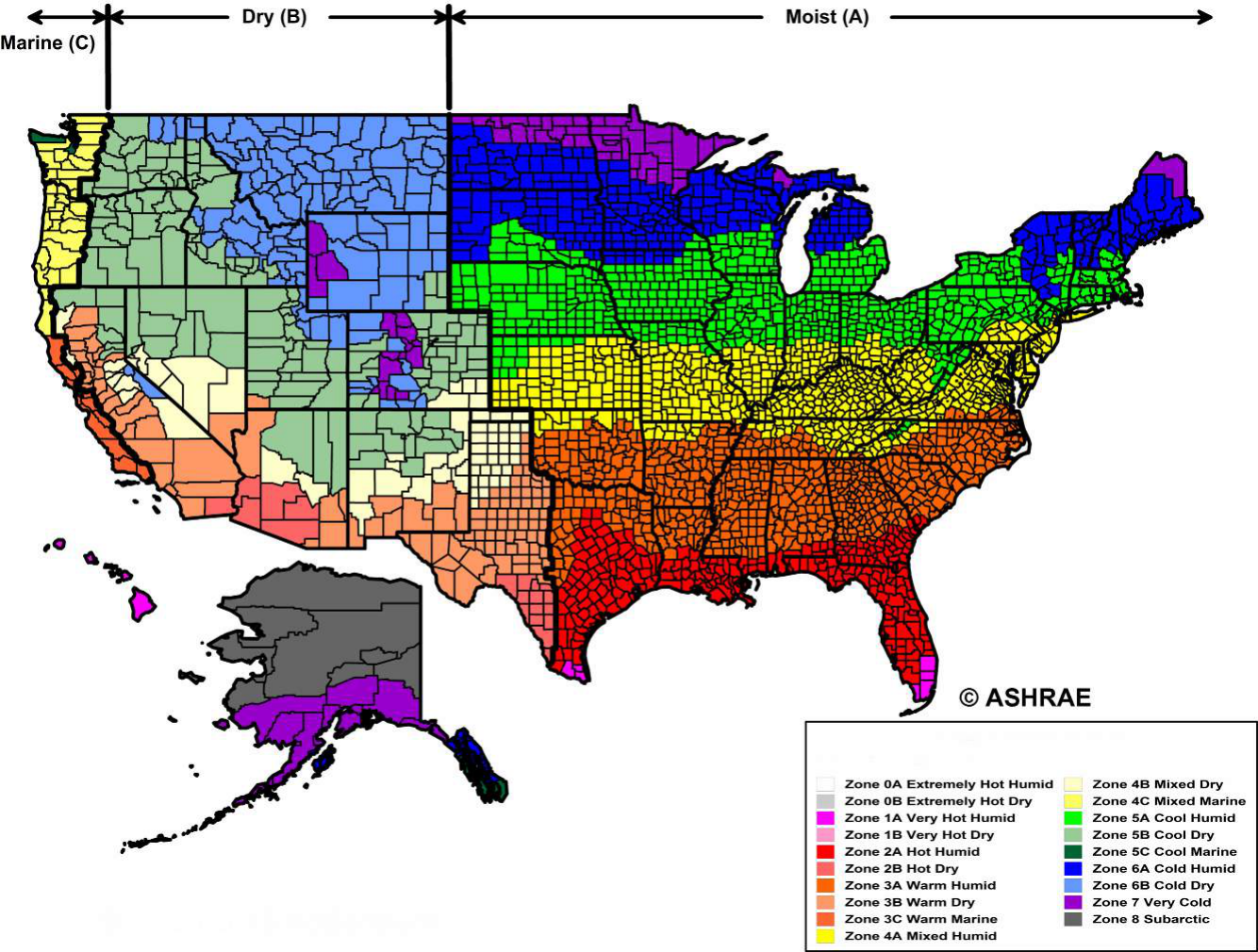
PDF Page 418
Table Annex1-2 ASHRAE Standard 169-2013, Table A-5: Canada Stations and Climate Zones
Precipitation
Precipitation
Province/LOCATION WMO# Lat Long CZ
mm in. Province/LOCATION WMO# Lat Long CZ mm in.
Alberta (AB) British Columbia (BC)
BANFF CS 711220 51.19 –115.55 7 487 19 ABBOTSFORD A 711080 49.03 –122.36 4C 1168 46
BOW ISLAND 712310 49.73 –111.45 6A 374 15 AGASSIZ CS 711130 49.25 –121.77 4C 1769 70
BOW VALLEY 712320 51.08 –115.07 7 584 23 ALERT BAY 711100 50.58 –126.93 5C 1668 66
BRETON PLOTS 712330 53.09 –114.44 7 460 18 AMPHITRITE POINT 711120 48.92 –125.54 5C 3212 126
BROOKS 714570 50.55 –111.85 6B 318 13 BALLENAS ISLAND 717690 49.35 –124.16 4C 981 39
CALGARY INT’L A 718770 51.11 –114.02 7 425 17 BLUE RIVER CS 718830 52.13 –119.29 6A 1032 41
CAMROSE 712540 53.03 –112.81 7 499 20 BONILLA ISLAND (AUT) 714840 53.50 –130.63 5C 2169 85
CARDSTON 711530 49.20 –113.29 6A 505 20 BURNS LAKE DECKER LAKE 719520 54.38 –125.96 7 503 20
CLARESHOLM 712340 50.00 –113.64 6A 433 17 CAPE SCOTT 711110 50.78 –128.43 5C 2296 90
COLD LAKE A 711200 54.42 –110.28 7 464 18 CAPE ST JAMES CS 711070 51.94 –131.02 5C 1599 63
COP UPPER 712350 51.08 –114.22 7 451 18 CATHEDRAL POINT (AUT) 714820 52.19 –127.47 5C 3439 135
CORONATION (AUT) 718730 52.08 –111.45 7 405 16 CLINTON (AUT) 714740 51.14 –121.50 7 392 15
CROWSNEST 712360 49.63 –114.48 7 664 26 COMOX A 718930 49.72 –124.90 5C 1340 53
DRUMHELLER EAST 712370 51.43 –112.67 7 390 15 CRANBROOK A 718800 49.61 –115.78 6A 408 16
EDMONTON CITY CENTRE A 718790 53.57 –113.52 7 481 19 CRESTON CAMPBELL SCIENTIFIC 717700 49.08 –116.50 5A 511 20
EDMONTON INT’L A 711230 53.32 –113.58 7 493 19 CUMSHEWA ISLAND 717710 53.03 –131.60 5C 2374 93
EDMONTON NAMAO A 711210 53.67 –113.47 7 457 18 DEASE LAKE 719580 58.43 –130.01 7 452 18
EDSON A 718810 53.60 –116.48 7 597 24 DISCOVERY ISLAND 710310 48.42 –123.23 4C 646 25
ELK ISLAND NAT PARK 712380 53.68 –112.87 7 442 17 ENTRANCE ISLAND CS 717720 49.22 –123.80 4C 1135 45
ESTHER 1 712400 51.67 –110.21 7 323 13 ESQUIMALT HARBOUR 717980 48.43 –123.44 4C 646 25
FORT CHIPEWYAN A 719330 58.77 –111.12 8 417 16 ESTEVAN POINT CS 718940 49.38 –126.54 5C 3276 129
FORT MCMURRAY A 719320 56.65 –111.22 7 476 19 FORT NELSON A 719450 58.84 –122.60 7 469 18
GARDEN RIVER 712530 58.71 –113.87 7 385 15 FORT ST JOHN A 719430 56.24 –120.74 7 477 19
GRANDE PRAIRIE A 719400 55.18 –118.88 7 477 19 GREY ISLET (AUT) 714760 54.58 –130.70 5A 2302 91
HIGH LEVEL A 710660 58.62 –117.16 8 441 17 HERBERT ISLAND (AUT) 714850 50.94 –127.64 5C 2155 85
HIGHVALE 712410 53.45 –114.47 7 458 18 HOLLAND ROCK 712190 54.17 –130.36 5C 2353 93
JASPER 718880 52.88 –118.07 7 415 16 HOPE 711140 49.37 –121.48 5C 1760 69
JASPER WARDEN 714860 52.93 –118.03 7 415 16 HOWE SOUND - PAM ROCKS 712110 49.49 –123.30 4C 1535 60
LAC LA BICHE (AUT) 729310 54.77 –112.02 7 457 18 KAMLOOPS A 718870 50.70 –120.44 5B 286 11
LACOMBE CDA 2 712420 52.45 –113.76 7 454 18 KELOWNA A 712030 49.96 –119.38 5A 471 19
LETHBRIDGE A 718740 49.63 –112.80 6A 425 17 KINDAKUN ROCKS (AUT) 714720 53.32 –132.77 5C 1981 78
LETHBRIDGE CDA 712430 49.70 –112.78 6A 425 17 LANGARA 718990 54.26 –133.06 5C 1952 77
LLOYDMINSTER A 718710 53.31 –110.07 7 426 17 LILLOOET 719990 50.68 –121.93 5A 392 15
MEDICINE HAT A 718720 50.02 –110.72 6B 347 14 LUCY ISLAND LIGHTSTATION 712200 54.30 –130.61 5C 2317 91
MILDRED LAKE 712550 57.04 –111.56 7 345 14 LYTTON 718910 50.22 –121.58 5C 455 18
MILK RIVER 712440 49.13 –112.05 6B 364 14 MACKENZIE A 719440 55.31 –123.14 7 687 27
NAKISKA RIDGETOP 712450 50.94 –115.19 8 605 24 MALAHAT 717740 48.57 –123.53 5C 1095 43
ONEFOUR CDA 711160 49.12 –110.47 6A 347 14 NAKUSP CS 712160 50.27 –117.81 5A 832 33
PEACE RIVER A 710680 56.23 –117.45 7 412 16 NELSON CS 717760 49.49 –117.31 5A 741 29
PINCHER CREEK (AUT) 718750 49.52 –113.98 6A 484 19 OSOYOOS CS 712150 49.03 –119.44 5B 319 13
RED DEER A 718780 52.18 –113.89 7 473 19 PEMBERTON AIRPORT CS 717770 50.30 –122.74 5C 850 33
RED EARTH 712460 56.55 –115.28 7 430 17 PENTICTON A 718890 49.46 –119.60 5B 303 12
ROCKY MTN HOUSE (AUT) 719280 52.42 –114.91 7 522 21 PITT MEADOWS CS 717750 49.21 –122.69 4C 1483 58
SLAVE LAKE A 710690 55.28 –114.78 7 525 21 POINT ATKINSON 710370 49.33 –123.26 4C 1535 60
SPRINGBANK A 718600 51.10 –114.37 7 491 19 PORT ALBERNI (AUT) 714750 49.32 –124.93 5C 1636 64
STAVELY AAFC 715550 50.18 –113.88 6A 472 19 PORT HARDY A 711090 50.68 –127.37 5C 1917 75
SUNDRE A 712480 51.78 –114.68 7 464 18 PRINCE GEORGE A 718960 53.89 –122.68 7 658 26
THREE HILLS 712490 51.83 –113.21 7 407 16 PRINCE RUPERT A 718980 54.29 –130.44 5C 2690 106
VAUXHALL CDA CS 712510 50.05 –112.13 6B 351 14 PRINCETON CS 710320 49.47 –120.51 6A 369 15
VEGREVILLE 714580 53.51 –112.10 7 375 15 PUNTZI MOUNTAIN (AUT) 710500 52.11 –124.14 7 394 16
WAINWRIGHT CFB AIRFIELD 21 711180 52.83 –111.10 7 431 17 QUESNEL A 711030 53.03 –122.51 6A 554 22
WATERTON PARK GATE 711540 49.13 –113.81 6A 551 22 REVELSTOKE A 718820 50.96 –118.18 6A 1018 40
WHITECOURT A 719300 54.14 –115.79 7 594 23 ROSE SPIT (AUT) 714770 54.16 –131.66 5A 1434 56
416 ANSI/ASHRAE/IES Standard 90.1-2022 (I-P)
PDF Page 419
Table Annex1-2 ASHRAE Standard 169-2013, Table A-5: Canada Stations and Climate Zones (Continued)
Precipitation
Precipitation
Province/LOCATION WMO# Lat Long CZ
mm in. Province/LOCATION WMO# Lat Long CZ mm in.
SALMON ARM CS 712180 50.70 –119.29 5A 458 18 VICTORIA BEACH (AUT) 715520 50.70 –96.57 7 489 19
SANDHEADS CS 712090 49.11 –123.30 4C 1082 43 WASAGAMING 714440 50.66 –99.94 7 528 21
SANDSPIT A 711010 53.25 –131.81 5C 1323 52 WILSON CREEK WEIR CS 711490 50.71 –99.53 7 536 21
SARTINE ISLAND (AUT) 714780 50.82 –128.91 5C 1920 76 WINNIPEG RICHARDSON INT’L A 718520 49.92 –97.23 7 523 21
SHERINGHAM POINT 717800 48.38 –123.92 5C 1497 59 New Brunswick (NB)
SISTERS ISLAND 717810 49.49 –124.43 4C 1103 43 BAS CARAQUET 715980 47.80 –64.83 6A 1049 41
SMITHERS A 719500 54.82 –127.18 7 539 21 CHARLO A 717110 47.98 –66.33 7 1112 44
SOLANDER ISLAND (AUT) 714790 50.11 –127.94 5C 2375 94 FREDERICTON A 717000 45.87 –66.53 6A 1151 45
SPARWOOD CS 717820 49.75 –114.89 7 1021 40 MIRAMICHI A 717170 47.01 –65.47 7 1090 43
SQUAMISH 712070 49.78 –123.16 5C 2294 90 MIRAMICHI RCS 717440 47.01 –65.46 6A 1090 43
SUMMERLAND CS 717680 49.56 –119.64 5B 321 13 MISCOU ISLAND (AUT) 717190 48.01 –64.49 7 1037 41
TERRACE A 719510 54.47 –128.58 6A 1378 54 MONCTON A 717050 46.10 –64.69 6A 1290 51
VANCOUVER HARBOUR CS 712010 49.30 –123.12 4C 1517 60 POINT ESCUMINAC (AUT) 714140 47.07 –64.80 6A 1133 45
VANCOUVER INT’L A 718920 49.20 –123.18 4C 1209 48 POINT LEPREAU CS 716990 45.07 –66.45 6A 1253 49
VERNON CS 711150 50.22 –119.19 5A 453 18 SAINT JOHN A 716090 45.32 –65.89 6A 1317 52
VICTORIA GONZALES CS 712000 48.41 –123.33 4C 646 25 ST LEONARD CS 710190 47.16 –67.83 7 997 39
VICTORIA HARTLAND CS 710380 48.53 –123.46 4C 948 37 ST STEPHEN (AUT) 716070 45.22 –67.25 6A 1149 45
VICTORIA INT’L A 717990 48.65 –123.43 5C 948 37 Newfoundland And Labrador (NL)
VICTORIA MARINE 712020 48.37 –123.75 5C 1265 50 ARGENTIA (AUT) 718070 47.29 –53.99 6A 1304 51
VICTORIA UNIVERSITY CS 717830 48.46 –123.30 4C 646 25 BADGER (AUT) 714000 48.97 –56.07 7 1072 42
WEST VANCOUVER AUT 717840 49.35 –123.19 4C 1517 60 BONAVISTA 711960 48.67 –53.11 6A 1068 42
WHITE ROCK CAMPBELL SCIENTIFI
717850 49.02 –122.78 4C 1049 41 BURGEO 2 711940 47.62 –57.62 6A 1818 72
WILLIAMS LAKE A 711040 52.18 –122.05 7 451 18 CAPE KAKKIVIAK 711760 59.98 –64.16 8 376 15
YOHO PARK 717860 51.44 –116.34 7 541 21 CAPE RACE (AUT) 718000 46.66 –53.08 6A 1378 54
Manitoba (MB) CARTWRIGHT 718180 53.71 –57.04 7 1060 42
BERENS RIVER CS 711580 52.36 –97.02 7 475 19 CHURCHILL FALLS 711820 53.56 –64.09 8 999 39
BRANDON A 711400 49.91 –99.95 7 471 19 COMFORT COVE 711930 49.27 –54.88 7 1213 48
CARBERRY CS 711700 49.91 –99.36 7 523 21 CORNER BROOK 719730 48.93 –57.92 6A 1222 48
CARMAN U OF M CS 711470 49.50 –98.03 7 527 21 DANIELS HARBOUR 711850 50.24 –57.58 7 1164 46
CHURCHILL A 719130 58.74 –94.06 8 449 18 DEER LAKE A 718090 49.22 –57.40 7 1105 44
DAUPHIN A 718550 51.10 –100.05 7 513 20 ENGLEE (AUT) 714170 50.72 –56.11 7 1022 40
DELTA MARSH CS 715630 50.18 –98.38 7 530 21 FEROLLE POINT (AUT) 714060 51.02 –57.10 7 1185 47
EMERSON AUT 715600 49.00 –97.24 7 488 19 GANDER INT’L A 718030 48.95 –54.58 7 1255 49
FISHER BRANCH (AUT) 714420 51.08 –97.55 7 562 22 GOOSE A 718160 53.32 –60.42 7 996 39
GEORGE ISLAND (AUT) 714450 52.82 –97.62 7 449 18 GRATES COVE 713360 48.17 –52.94 6A 1408 55
GILLAM A 719120 56.36 –94.71 8 518 20 HOPEDALE (AUT) 719000 55.45 –60.22 8 884 35
GIMLI INDUSTRIAL PARK 718560 50.63 –97.05 7 500 20 LA SCIE 713370 49.92 –55.67 7 1293 51
GRAND RAPIDS (AUT) 718580 53.19 –99.27 7 485 19 MARTICOT ISLAND 716920 47.33 –54.59 6A 1395 55
GRETNA (AUT) 714410 49.03 –97.56 7 512 20 POOLS ISLAND 719310 49.11 –53.58 6A 1015 40
HUNTERS POINT MARINE 711420 53.03 –100.93 7 462 18 PORT AUX BASQUES 711970 47.57 –59.15 7 1563 62
ISLAND LAKE A 711450 53.85 –94.65 7 581 23 SAGLEK 713350 58.33 –62.59 8 836 33
LYNN LAKE A 710780 56.86 –101.08 8 535 21 SAGONA ISLAND 714080 47.37 –55.79 6A 1574 62
MELITA 714470 49.28 –100.99 7 446 18 ST ANTHONY 715580 51.38 –56.10 7 1183 47
NORWAY HOUSE A 711410 53.95 –97.85 7 530 21 ST JOHN’S A 718010 47.62 –52.74 6A 1547 61
OAKPOINT MARINE 711440 50.50 –98.04 7 532 21 ST LAWRENCE 718020 46.92 –55.38 6A 1603 63
PILOT MOUND (AUT) 711480 49.19 –98.90 7 487 19 STEPHENVILLE A 718150 48.53 –58.55 6A 1364 54
PINAWA 714480 50.18 –96.06 7 435 17 TWILLINGATE (AUT) 714020 49.68 –54.80 7 1015 40
PORTAGE SOUTHPORT A 718510 49.90 –98.27 7 515 20 WABUSH LAKE A 718250 52.93 –66.87 8 936 37
ROBLIN 715530 51.18 –101.36 7 466 18 Nova Scotia (NS)
SHOAL LAKE CS 711500 50.45 –100.60 7 504 20 AMHERST (AUT) 714100 45.85 –64.27 6A 1212 48
SPRAGUE 714490 49.02 –95.60 7 622 24 BACCARO POINT 716910 43.45 –65.47 6A 1258 50
SWAN RIVER RCS 714430 52.12 –101.23 7 468 18 BEAVER ISLAND (AUT) 714030 44.82 –62.33 6A 1472 58
THE PAS A 718670 53.97 –101.10 7 470 18 BRIER ISLAND 719880 44.29 –66.35 6A 1202 47
THOMPSON A 710790 55.80 –97.86 8 520 20 CARIBOU POINT (AUT) 714150 45.77 –62.68 6A 1063 42
ANSI/ASHRAE/IES Standard 90.1-2022 (I-P) 417
PDF Page 420
Table Annex1-2 ASHRAE Standard 169-2013, Table A-5: Canada Stations and Climate Zones (Continued)
Precipitation
Precipitation
Province/LOCATION WMO# Lat Long CZ
mm in. Province/LOCATION WMO# Lat Long CZ mm in.
GRAND ETANG 715970 46.55 –61.05 6A 1202 47 CROKER RIVER 710590 69.28 –119.22 8 183 7
GREENWOOD A 713970 44.98 –64.92 6A 1253 49 DEWAR LAKES 710920 68.65 –71.17 8 248 10
HALIFAX STANFIELD INT’L A 713950 44.88 –63.52 6A 1532 60 ENNADAI LAKE (AUT) 719230 61.13 –100.88 8 326 13
HART ISLAND (AUT) 714190 45.35 –60.98 6A 1464 58 EUREKA 719170 79.98 –85.93 8 76 3
KEJIMKUJIK 1 715990 44.43 –65.20 6A 1438 57 FOX FIVE 710960 67.54 –63.79 8 289 11
SABLE ISLAND 716000 43.93 –60.01 5A 1392 55 GLADMAN POINT A 719270 68.67 –97.80 8 125 5
SHEARWATER A 716010 44.63 –63.50 6A 1414 56 HALL BEACH A 710810 68.78 –81.24 8 235 9
SHEARWATER JETTY CAN35X 44.63 –63.52 5A 1414 56 HAT ISLAND 710840 68.32 –100.09 8 204 8
ST PAUL ISLAND (AUT) 714180 47.23 –60.14 6A 1391 55 IQALUIT A 719090 63.75 –68.55 8 422 17
SYDNEY A 717070 46.17 –60.05 6A 1523 60 JENNY LIND ISLAND A 710710 68.65 –101.73 8 116 5
WESTERN HEAD 714110 43.99 –64.66 6A 1405 55 KUGLUKTUK A 719380 67.82 –115.14 8 263 10
YARMOUTH A 716030 43.83 –66.09 6A 1305 51 LADY FRANKLIN POINT A 719370 68.50 –113.22 8 121 5
Northwest Territories (NT) LONGSTAFF BLUFF 710910 68.90 –75.14 8 212 8
AULAVIK NATIONAL PARK 719740 74.14 –119.99 8 116 5 MACKAR INLET 710800 68.30 –85.67 8 187 7
CAPE PARRY A 719480 70.17 –124.72 8 154 6 PANGNIRTUNG 718260 66.15 –65.72 8 427 17
COLVILLE LAKE 710550 67.04 –126.08 8 317 12 PELLY BAY 719190 68.43 –89.72 8 240 9
FORT GOOD HOPE CS 714910 66.24 –128.64 8 317 12 POND INLET A 710950 72.68 –77.98 8 196 8
FORT LIARD 714970 60.23 –123.47 8 435 17 RANKIN INLET A 710830 62.82 –92.12 8 324 13
FORT PROVIDENCE 710870 61.32 –117.60 8 266 10 RESOLUTE CARS 719240 74.72 –94.99 8 152 6
FORT RELIANCE 710730 62.72 –109.17 8 283 11 RESOLUTION ISLAND 719720 61.60 –64.63 8 364 14
FORT SIMPSON A 719460 61.76 –121.24 8 376 15 ROBERTSON LAKE (AUT) 714900 65.10 –102.43 8 256 10
FORT SMITH A 719340 60.02 –111.96 8 373 15 SHEPHERD BAY A 719110 68.82 –93.43 8 155 6
HANBURY RIVER 719630 63.60 –105.13 8 275 11 Ontario (ON)
HAY RIVER A 719350 60.84 –115.78 8 373 15 ARMSTRONG (AUT) 718410 50.29 –88.91 7 737 29
INNER WHALEBACKS 711620 61.92 –113.73 8 283 11 ATIKOKAN (AUT) 717470 48.76 –91.63 7 798 31
INUVIK A 719570 68.30 –133.48 8 267 11 BANCROFT AUTO 712940 45.07 –77.88 7 873 34
LAC LA MARTRE 711630 63.13 –117.25 8 265 10 BEAUSOLEIL 712720 44.85 –79.87 6A 934 37
LINDBURG LANDING 716820 61.12 –122.85 8 399 16 BELLE RIVER 712730 42.30 –82.70 5A 804 32
LITTLE CHICAGO 711640 67.18 –130.23 8 310 12 BIG TROUT LAKE 718480 53.83 –89.87 8 582 23
LIVERPOOL BAY 719600 69.60 –130.91 8 130 5 BIG TROUT LAKE READAC 718440 53.82 –89.90 8 582 23
MOULD BAY A 710720 76.23 –119.33 8 114 4 BURLINGTON PIERS (AUT) 714370 43.30 –79.80 5A 827 33
NICHOLSON PENINSULA 719560 69.93 –128.97 8 107 4 COBOURG (AUT) 714310 43.95 –78.17 6A 808 32
NORMAN WELLS A 710430 65.28 –126.80 8 336 13 COLLINGWOOD 712700 44.50 –80.22 6A 766 30
PELLY ISLAND 715020 69.63 –135.44 8 194 8 COVE ISLAND (AUT) 714390 45.33 –81.73 6A 869 34
RAE LAKES 711650 64.11 –117.33 8 260 10 EARLTON A 717350 47.70 –79.85 7 801 32
SACHS HARBOUR CLIMATE 714670 71.99 –125.25 8 134 5 ERIEAU (AUT) 714650 42.25 –81.90 5A 797 31
TROUT LAKE 711660 60.44 –121.24 8 405 16 GERALDTON A 718340 49.78 –86.93 7 774 30
TUKTOYAKTUK 719850 69.43 –133.02 8 136 5 GODERICH 712610 43.77 –81.72 5A 981 39
YELLOWKNIFE A 719360 62.46 –114.44 8 287 11 GORE BAY A 717330 45.88 –82.57 6A 834 33
YOHIN 710200 61.24 –123.74 8 413 16 GREAT DUCK ISLAND (AUT) 714620 45.63 –82.95 6A 809 32
Nunavut (NU) GRENADIER ISLAND 712810 44.42 –75.85 6A 947 37
ALERT 710820 82.52 –62.28 8 172 7 KAPUSKASING A 718310 49.41 –82.47 7 891 35
BAKER LAKE A 719260 64.30 –96.08 8 272 11 KENORA A 718500 49.79 –94.37 7 674 27
BREVOORT ISLAND 710970 63.34 –64.15 8 624 25 KILLARNEY (AUT) 714600 45.97 –81.48 6A 839 33
BYRON BAY A 719290 68.75 –109.07 8 121 5 LAGOON CITY 712820 44.55 –79.22 6A 929 37
CAMBRIDGE BAY A 719250 69.11 –105.14 8 149 6 LANSDOWNE HOUSE (AUT) 718460 52.20 –87.94 7 719 28
CAPE DORSET A 719100 64.23 –76.53 8 402 16 LONDON INT’L AIRPORT 716230 43.03 –81.15 5A 981 39
CAPE DYER 710940 66.65 –61.38 8 627 25 LONG POINT (AUT) 714640 42.57 –80.05 5A 948 37
CAPE HOOPER 710930 68.47 –66.82 8 265 10 MOOSONEE A 718360 51.29 –80.61 7 722 28
CAPE MERCY 719750 64.96 –63.58 8 467 18 MOUNT FOREST (AUT) 716310 43.98 –80.75 6A 969 38
CAPE PEEL WEST 710640 69.04 –107.82 8 133 5 NAGAGAMI (AUT) 718320 49.75 –84.16 7 793 31
CLINTON POINT 710530 69.58 –120.80 8 161 6 NORTH BAY A 717310 46.36 –79.42 7 1012 40
CLYDE A 710900 70.49 –68.52 8 239 9 OTTAWA MACDONALD-CARTIER INT’
716280 45.32 –75.67 6A 922 36
CORAL HARBOUR A 719150 64.19 –83.36 8 299 12 PEAWANUCK (AUT) 714340 54.98 –85.43 8 602 24
418 ANSI/ASHRAE/IES Standard 90.1-2022 (I-P)
PDF Page 421
Table Annex1-2 ASHRAE Standard 169-2013, Table A-5: Canada Stations and Climate Zones (Continued)
Precipitation
Precipitation
Province/LOCATION WMO# Lat Long CZ
mm in. Province/LOCATION WMO# Lat Long CZ mm in.
PETAWAWA A 716250 45.95 –77.32 7 851 34 INUKJUAK A 719070 58.47 –78.08 8 457 18
PETERBOROUGH A 716290 44.23 –78.37 6A 843 33 JONQUIERE 716170 48.42 –71.15 7 948 37
PICKLE LAKE (AUT) 718350 51.45 –90.22 7 726 29 KUUJJUAQ A 719060 58.10 –68.42 8 520 20
POINT PETRE (AUT) 714300 43.83 –77.15 6A 965 38 KUUJJUARAPIK A 719050 55.28 –77.75 8 667 26
PORT COLBORNE (AUT) 714630 42.87 –79.25 5A 986 39 LA BAIE 713880 48.30 –70.92 7 966 38
PORT WELLER (AUT) 714320 43.25 –79.22 5A 890 35 LA GRANDE IV A 718230 53.76 –73.68 8 773 30
PUKASKWA (AUT) 717500 48.59 –86.29 7 865 34 LA GRANDE RIVIERE A 718270 53.63 –77.70 8 683 27
RED LAKE A 718540 51.07 –93.79 7 668 26 LA POCATIERE 717130 47.36 –70.03 6A 963 38
ROYAL ISLAND (AUT) CAN21X 49.47 –94.76 7 613 24 LA TUQUE 713780 47.41 –72.79 7 959 38
SAULT STE MARIE A 712600 46.48 –84.51 6A 932 37 LAC BENOIT 715200 51.53 –71.11 8 925 36
SIOUX LOOKOUT A 718420 50.12 –91.90 7 739 29 LAC EON 714210 51.87 –63.28 8 1058 42
SUDBURY A 717300 46.62 –80.80 7 917 36 LAC SAINT-PIERRE 711980 46.18 –72.92 6A 993 39
THUNDER BAY A 717490 48.37 –89.33 7 731 29 L’ACADIE 713720 45.29 –73.35 6A 1021 40
TIMMINS VICTOR POWER A 717390 48.57 –81.38 7 921 36 L’ASSOMPTION 715240 45.81 –73.43 6A 999 39
TORONTO BUTTONVILLE A 716390 43.86 –79.37 6A 781 31 LENNOXVILLE 716110 45.37 –71.82 6A 1095 43
TORONTO ISLAND A 712650 43.63 –79.40 5A 848 33 L’ETAPE 713820 47.56 –71.23 7 1261 50
TORONTO LESTER B. PEARSON INT
716240 43.68 –79.63 5A 785 31 LONGUE-POINTE-DE-MINGAN 715120 50.27 –64.23 7 1108 44
TRENTON A 716210 44.12 –77.53 6A 858 34 MANIWAKI AIRPORT 717210 46.27 –75.99 7 966 38
UPSALA (AUT) 714350 49.03 –90.47 7 715 28 MANIWAKI UA 717220 46.30 –76.01 7 928 37
WAWA (AUT) 717380 47.97 –84.78 7 906 36 MANOUANE EST 715210 50.66 –70.53 8 908 36
WELCOME ISLAND (AUT) 717510 48.37 –89.12 7 659 26 MATAGAMI A 718210 49.77 –77.80 7 838 33
WIARTON A 716330 44.75 –81.11 6A 1049 41 MCTAVISH 716120 45.50 –73.58 6A 1096 43
WINDSOR A 715380 42.28 –82.96 5A 920 36 MISTOOK 713810 48.60 –71.72 7 942 37
Prince Edward Island (PE) MONT-JOLI A 717180 48.60 –68.22 7 969 38
CHARLOTTETOWN A 717060 46.29 –63.13 6A 1217 48 MONT-ORFORD 716180 45.31 –72.24 7 1082 43
EAST POINT (AUT) 714120 46.46 –61.99 6A 1285 51 MONTREAL/MIRABEL INT’L A 716260 45.67 –74.03 6A 1024 40
NORTH CAPE 719870 47.06 –64.00 6A 1103 43 MONTREAL/PIERRE ELLIOTT TRUDE
716270 45.47 –73.75 6A 988 39
SUMMERSIDE 717020 46.44 –63.84 6A 1077 42 MONTREAL/ST-HUBERT A 713710 45.52 –73.42 6A 1027 40
Quebec (QC) MONTREAL-EST 716750 45.63 –73.55 6A 1013 40
AMQUI 713860 48.47 –67.43 7 1028 40 NATASHQUAN A 718130 50.18 –61.82 7 1182 47
BAGOTVILLE A 717270 48.33 –71.00 7 966 38 NEW CARLISLE 1 716190 48.01 –65.33 7 1015 40
BAIE-COMEAU 718290 49.26 –68.15 7 981 39 NICOLET 717230 46.23 –72.66 6A 1026 40
BAIE-COMEAU A 711870 49.13 –68.20 7 1045 41 NORMANDIN 713790 48.84 –72.55 7 913 36
BARRAGE TEMISCAMINGUE 717320 46.71 –79.10 6A 956 38 ONATCHIWAY 713870 48.89 –71.03 7 937 37
BEAUCEVILLE 713230 46.20 –70.78 7 1127 44 PARENT 717260 47.92 –74.62 7 1015 40
BLANC-SABLON A 718080 51.45 –57.18 7 1091 43 POINTE CLAVEAU 711890 48.26 –70.11 7 995 39
BONNARD 1 713830 50.73 –71.01 7 1006 40 POINTE NOIRE CS 713900 50.16 –66.43 7 1119 44
CAP-CHAT 714280 49.11 –66.65 7 928 37 POINTE-AU-PERE (INRS) 715540 48.51 –68.47 7 888 35
CAP-D’ESPOIR 714290 48.42 –64.32 7 1089 43 POINTE-DES-MONTS 714270 49.32 –67.38 7 982 39
CAP-MADELEINE 714250 49.25 –65.32 7 897 35 PORT-MENIER 718100 49.84 –64.29 7 1047 41
CAP-ROUGE 711860 48.37 –70.54 7 944 37 QUEBEC/JEAN LESAGE INTL A 717080 46.80 –71.38 7 1266 50
CAP-TOURMENTE 713840 47.08 –70.78 6A 1104 43 RIVIERE-DU-LOUP 717150 47.81 –69.55 7 981 39
CHARLEVOIX (MRC) 713190 47.28 –70.64 7 1103 43 ROBERVAL A 717280 48.52 –72.27 7 872 34
CHEVERY 718140 50.46 –59.64 7 1161 46 ROUYN 717340 48.25 –79.03 7 865 34
CHIBOUGAMAU CHAPAIS A 718220 49.77 –74.53 7 969 38 ROUYN A 717400 48.22 –78.83 7 882 35
CHUTE-DES-PASSES 715220 49.84 –71.17 7 1091 43 SCHEFFERVILLE A 718280 54.80 –66.82 8 784 31
DESCHAMBAULT 713890 46.69 –71.97 7 1134 45 SEPT-ILES A 718110 50.22 –66.27 7 1173 46
FRELIGHSBURG 713730 45.05 –72.86 6A 1180 46 SHERBROOKE A 716100 45.43 –71.68 7 1162 46
GASPE A 711880 48.78 –64.48 7 1048 41 ST-ANICET 1 717120 45.12 –74.29 6A 968 38
HAVRE-SAINT-PIERRE A 713130 50.28 –63.60 7 1094 43 STE AGATHE DES MONTS 717200 46.05 –74.28 7 1236 49
HEATH POINT 714230 49.09 –61.70 7 1030 41 STE-ANNE-DE-BELLEVUE 1 713770 45.43 –73.93 6A 958 38
ILE AUX PERROQUETS 713750 50.22 –64.21 7 1099 43 STE-CLOTHILDE 716140 45.17 –73.68 6A 925 36
ILE ROUGE 714260 48.07 –69.56 7 998 39 STE-FOY (U. LAVAL) 713920 46.78 –71.29 6A 1266 50
ILES DE LA MADELEINE 717100 47.43 –61.77 6A 1049 41 ST-JOVITE 713760 46.08 –74.56 7 1130 44
ANSI/ASHRAE/IES Standard 90.1-2022 (I-P) 419
PDF Page 422
Table Annex1-2 ASHRAE Standard 169-2013, Table A-5: Canada Stations and Climate Zones (Continued)
Precipitation
Precipitation
Province/LOCATION WMO# Lat Long CZ
mm in. Province/LOCATION WMO# Lat Long CZ mm in.
TROIS-RIVIERES 717240 46.35 –72.52 6A 1024 40 ROCKGLEN (AUT) 711350 49.17 –105.98 7 335 13
VAL-D’OR A 717250 48.06 –77.79 7 981 39 ROSETOWN EAST 715100 51.57 –107.92 7 347 14
VARENNES 711840 45.72 –73.38 6A 1027 40 SASKATOON DIEFENBAKER INT’L A
718660 52.17 –106.72 7 364 14
Saskatchewan (SK) SASKATOON KERNEN FARM 715130 52.15 –106.55 7 364 14
ASSINIBOIA AIRPORT 714870 49.73 –105.93 7 400 16 SCOTT CDA 714890 52.36 –108.83 7 388 15
BROADVIEW 718610 50.37 –102.57 7 416 16 SOUTHEND 714510 56.33 –103.28 8 535 21
COLLINS BAY 710750 58.18 –103.70 8 546 21 SPIRITWOOD WEST 711330 53.37 –107.55 7 417 16
CORONACH SPC 715160 49.05 –105.48 7 338 13 STONY RAPIDS A 711320 59.25 –105.83 8 429 17
CREE LAKE 719200 57.35 –107.13 8 476 19 SWIFT CURRENT A 718700 50.30 –107.68 7 389 15
CYPRESS HILLS PARK 711390 49.65 –109.52 7 346 14 SWIFT CURRENT CDA 714460 50.27 –107.73 7 389 15
EASTEND CYPRESS (AUT) 711310 49.43 –108.98 7 386 15 URANIUM CITY (AUT) 710760 59.57 –108.48 8 379 15
ELBOW CS 714500 51.13 –106.58 7 325 13 VAL MARIE SOUTHEAST 711370 49.07 –107.58 7 295 12
ESTEVAN A 718620 49.22 –102.97 7 434 17 WASKESIU LAKE 714540 53.92 –106.07 7 414 16
HUDSON BAY 718680 52.82 –102.32 7 479 19 WATROUS EAST 715110 51.67 –105.40 7 379 15
INDIAN HEAD CDA 715150 50.55 –103.65 7 444 17 WEYBURN 714520 49.70 –103.80 7 391 15
KEY LAKE A 714880 57.25 –105.60 8 493 19 WYNYARD (AUT) 718650 51.77 –104.20 7 429 17
KINDERSLEY A 711290 51.52 –109.18 7 324 13 YORKTON A 711380 51.27 –102.47 7 457 18
LA RONGE A 719220 55.15 –105.27 7 501 20 Yukon (YT)
LAST MOUNTAIN CS 715560 51.42 –105.25 7 384 15 BURWASH A 719670 61.37 –139.05 8 302 12
LEADER AIRPORT 714590 50.90 –109.50 7 365 14 FARO (AUT) 719490 62.23 –133.35 8 275 11
LUCKY LAKE 714550 50.95 –107.15 7 342 13 HAINES JUNCTION 715050 60.77 –137.58 8 334 13
MAPLE CREEK 714530 49.90 –109.47 6A 371 15 HERSCHEL ISLAND 715010 69.57 –138.91 8 188 7
MEADOW LAKE A 711250 54.13 –108.52 7 431 17 IVVAVIK NAT. PARK 719780 69.16 –140.15 8 176 7
MELFORT 714560 52.82 –104.60 7 416 16 KOMAKUK BEACH 710460 69.61 –140.20 8 168 7
MOOSE JAW A 718640 50.33 –105.55 7 375 15 MAYO A 719650 63.62 –135.87 8 329 13
MOOSE JAW CS 715390 50.33 –105.56 7 375 15 ROCK RIVER 715060 66.98 –136.22 8 337 13
NIPAWIN A 711300 53.33 –104.00 7 453 18 SHINGLE POINT A 719680 68.95 –137.22 8 260 10
NORTH BATTLEFORD A 718760 52.77 –108.26 7 391 15 TESLIN (AUT) 710450 60.17 –132.73 8 340 13
OUTLOOK PFRA 715510 51.48 –107.05 7 350 14 WATSON LAKE A 719530 60.12 –128.82 8 436 17
PRINCE ALBERT A 718690 53.22 –105.67 7 426 17 WHITEHORSE A 719640 60.71 –135.07 7 281 11
REGINA A 718630 50.43 –104.67 7 395 16
420 ANSI/ASHRAE/IES Standard 90.1-2022 (I-P)
PDF Page 423
Table Annex1-3 ASHRAE Standard 169-2013, Table A-6: International Stations and Climate Zones
| Precipitation Country/LOCATION WMO# Lat Long CZ mm in. | Precipitation Country/LOCATION WMO# Lat Long CZ mm in. |
|---|---|
| Albania (ALB) TIRANA 136150 41.33 19.78 3A 1234 49 | HALLEY 890220 –75.50 –26.65 8 307 12 MANUELA 898640 –74.95 163.69 8 350 14 MARBLE POINT 898660 –77.43 163.75 8 190 7 MAWSON 895640 –67.60 62.87 8 307 12 MIRNYJ 895920 –66.55 93.02 8 745 29 MOLODEZNAJA 895420 –67.67 45.85 8 529 21 MOUNT SIPLE 893270 –73.20 –127.05 8 504 20 NEUMAYER 890020 –70.67 –8.25 8 394 16 NOVOLAZAREVSKAJA 895120 –70.77 11.83 8 354 14 POSSESSION ISLAND 898790 –71.89 171.21 8 453 18 SIPLE DOME 893450 –81.65 –148.77 8 285 11 SYOWA 895320 –69.00 39.58 8 449 18 |
| Algeria (DZA) ADRAR 606200 27.88 –0.18 1B 14 1 ANNABA 603600 36.83 7.82 3A 630 25 BATNA 604680 35.75 6.32 3B 362 14 BECHAR 605710 31.50 –2.25 2B 87 3 BEJAIA-AEROPORT 604020 36.72 5.07 3A 776 31 BISKRA 605250 34.80 5.73 2B 110 4 BORDJ-BOU-ARRERIDJ 604440 36.07 4.77 3B 420 17 CONSTANTINE 604190 36.28 6.62 3A 516 20 DAR-EL-BEIDA 603900 36.68 3.22 3A 701 28 DJANET 606700 24.27 9.47 2B 21 1 EL-BAYADH 605500 33.67 1.00 4B 269 11 EL-GOLEA 605900 30.57 2.87 2B 37 1 EL-OUED 605590 33.50 6.78 2B 71 3 GHARDAIA 605660 32.40 3.80 2B 65 3 HASSI-MESSAOUD 605810 31.67 6.15 2B 40 2 ILLIZI 606400 26.50 8.42 1B 18 1 IN-AMENAS 606110 28.05 9.63 2B 25 1 IN-SALAH 606300 27.23 2.50 0B 12 0 JIJEL-ACHOUAT 603510 36.80 5.88 3A 943 37 MASCARA-MATEMORE 605060 35.60 0.30 3A 443 17 MECHERIA 605490 33.58 –0.28 3B 231 9 ORAN-SENIA 604900 35.63 –0.60 3A 368 15 OUARGLA 605800 31.93 5.40 2B 50 2 SETIF 604450 36.18 5.25 4A 492 19 SKIKDA 603550 36.88 6.90 3A 734 29 TAMANRASSET 606800 22.80 5.43 2B 40 2 TAMANRASSET 606805 22.80 5.45 2B 40 2 TEBESSA 604750 35.42 8.12 3B 369 15 TIARET 605110 35.35 1.47 3B 355 14 TINDOUF 606560 27.70 –8.17 1B 51 2 TLEMCEN-ZENATA 605310 35.02 –1.47 3A 468 18 TOUGGOURT 605550 33.12 6.13 2B 58 2 | Algeria (DZA) ADRAR 606200 27.88 –0.18 1B 14 1 ANNABA 603600 36.83 7.82 3A 630 25 BATNA 604680 35.75 6.32 3B 362 14 BECHAR 605710 31.50 –2.25 2B 87 3 BEJAIA-AEROPORT 604020 36.72 5.07 3A 776 31 BISKRA 605250 34.80 5.73 2B 110 4 BORDJ-BOU-ARRERIDJ 604440 36.07 4.77 3B 420 17 CONSTANTINE 604190 36.28 6.62 3A 516 20 DAR-EL-BEIDA 603900 36.68 3.22 3A 701 28 DJANET 606700 24.27 9.47 2B 21 1 EL-BAYADH 605500 33.67 1.00 4B 269 11 EL-GOLEA 605900 30.57 2.87 2B 37 1 EL-OUED 605590 33.50 6.78 2B 71 3 GHARDAIA 605660 32.40 3.80 2B 65 3 HASSI-MESSAOUD 605810 31.67 6.15 2B 40 2 ILLIZI 606400 26.50 8.42 1B 18 1 IN-AMENAS 606110 28.05 9.63 2B 25 1 IN-SALAH 606300 27.23 2.50 0B 12 0 JIJEL-ACHOUAT 603510 36.80 5.88 3A 943 37 MASCARA-MATEMORE 605060 35.60 0.30 3A 443 17 MECHERIA 605490 33.58 –0.28 3B 231 9 ORAN-SENIA 604900 35.63 –0.60 3A 368 15 OUARGLA 605800 31.93 5.40 2B 50 2 SETIF 604450 36.18 5.25 4A 492 19 SKIKDA 603550 36.88 6.90 3A 734 29 TAMANRASSET 606800 22.80 5.43 2B 40 2 TAMANRASSET 606805 22.80 5.45 2B 40 2 TEBESSA 604750 35.42 8.12 3B 369 15 TIARET 605110 35.35 1.47 3B 355 14 TINDOUF 606560 27.70 –8.17 1B 51 2 TLEMCEN-ZENATA 605310 35.02 –1.47 3A 468 18 TOUGGOURT 605550 33.12 6.13 2B 58 2 |
| Algeria (DZA) ADRAR 606200 27.88 –0.18 1B 14 1 ANNABA 603600 36.83 7.82 3A 630 25 BATNA 604680 35.75 6.32 3B 362 14 BECHAR 605710 31.50 –2.25 2B 87 3 BEJAIA-AEROPORT 604020 36.72 5.07 3A 776 31 BISKRA 605250 34.80 5.73 2B 110 4 BORDJ-BOU-ARRERIDJ 604440 36.07 4.77 3B 420 17 CONSTANTINE 604190 36.28 6.62 3A 516 20 DAR-EL-BEIDA 603900 36.68 3.22 3A 701 28 DJANET 606700 24.27 9.47 2B 21 1 EL-BAYADH 605500 33.67 1.00 4B 269 11 EL-GOLEA 605900 30.57 2.87 2B 37 1 EL-OUED 605590 33.50 6.78 2B 71 3 GHARDAIA 605660 32.40 3.80 2B 65 3 HASSI-MESSAOUD 605810 31.67 6.15 2B 40 2 ILLIZI 606400 26.50 8.42 1B 18 1 IN-AMENAS 606110 28.05 9.63 2B 25 1 IN-SALAH 606300 27.23 2.50 0B 12 0 JIJEL-ACHOUAT 603510 36.80 5.88 3A 943 37 MASCARA-MATEMORE 605060 35.60 0.30 3A 443 17 MECHERIA 605490 33.58 –0.28 3B 231 9 ORAN-SENIA 604900 35.63 –0.60 3A 368 15 OUARGLA 605800 31.93 5.40 2B 50 2 SETIF 604450 36.18 5.25 4A 492 19 SKIKDA 603550 36.88 6.90 3A 734 29 TAMANRASSET 606800 22.80 5.43 2B 40 2 TAMANRASSET 606805 22.80 5.45 2B 40 2 TEBESSA 604750 35.42 8.12 3B 369 15 TIARET 605110 35.35 1.47 3B 355 14 TINDOUF 606560 27.70 –8.17 1B 51 2 TLEMCEN-ZENATA 605310 35.02 –1.47 3A 468 18 TOUGGOURT 605550 33.12 6.13 2B 58 2 | Antigua and Barbuda (ATG) VC BIRD INTL AIRPOR 788620 17.12 –61.78 0A 883 35 |
| Algeria (DZA) ADRAR 606200 27.88 –0.18 1B 14 1 ANNABA 603600 36.83 7.82 3A 630 25 BATNA 604680 35.75 6.32 3B 362 14 BECHAR 605710 31.50 –2.25 2B 87 3 BEJAIA-AEROPORT 604020 36.72 5.07 3A 776 31 BISKRA 605250 34.80 5.73 2B 110 4 BORDJ-BOU-ARRERIDJ 604440 36.07 4.77 3B 420 17 CONSTANTINE 604190 36.28 6.62 3A 516 20 DAR-EL-BEIDA 603900 36.68 3.22 3A 701 28 DJANET 606700 24.27 9.47 2B 21 1 EL-BAYADH 605500 33.67 1.00 4B 269 11 EL-GOLEA 605900 30.57 2.87 2B 37 1 EL-OUED 605590 33.50 6.78 2B 71 3 GHARDAIA 605660 32.40 3.80 2B 65 3 HASSI-MESSAOUD 605810 31.67 6.15 2B 40 2 ILLIZI 606400 26.50 8.42 1B 18 1 IN-AMENAS 606110 28.05 9.63 2B 25 1 IN-SALAH 606300 27.23 2.50 0B 12 0 JIJEL-ACHOUAT 603510 36.80 5.88 3A 943 37 MASCARA-MATEMORE 605060 35.60 0.30 3A 443 17 MECHERIA 605490 33.58 –0.28 3B 231 9 ORAN-SENIA 604900 35.63 –0.60 3A 368 15 OUARGLA 605800 31.93 5.40 2B 50 2 SETIF 604450 36.18 5.25 4A 492 19 SKIKDA 603550 36.88 6.90 3A 734 29 TAMANRASSET 606800 22.80 5.43 2B 40 2 TAMANRASSET 606805 22.80 5.45 2B 40 2 TEBESSA 604750 35.42 8.12 3B 369 15 TIARET 605110 35.35 1.47 3B 355 14 TINDOUF 606560 27.70 –8.17 1B 51 2 TLEMCEN-ZENATA 605310 35.02 –1.47 3A 468 18 TOUGGOURT 605550 33.12 6.13 2B 58 2 | Argentina (ARG) AEROPARQUE BS. AS. 875820 –34.57 –58.42 3A 1049 41 BAHIA BLANCA AERO 877500 –38.73 –62.17 3A 632 25 BARILOCHE AERO 877650 –41.15 –71.17 5C 801 32 CATAMARCA AERO. 872220 –28.60 –65.77 2B 383 15 CERES AERO 872570 –29.88 –61.95 3A 936 37 COMODORO RIVADAVIA 878600 –45.78 –67.50 4C 238 9 CONCORDIA AERO 873950 –31.30 –58.02 3A 1298 51 CORDOBA AERO 873440 –31.32 –64.22 3A 827 33 CORRIENTES AERO. 871660 –27.45 –58.77 2A 1460 57 ESQUEL AERO 878030 –42.93 –71.15 5C 488 19 EZEIZA AERO 875760 –34.82 –58.53 3A 967 38 FORMOSA AERO 871620 –26.20 –58.23 2A 1411 56 GUALEGUAYCHU AERO 874970 –33.00 –58.62 3A 1038 41 IGUAZU AERO 870970 –25.73 –54.47 2A 1826 72 JUJUY AERO 870460 –24.38 –65.08 3A 818 32 JUNIN AERO 875480 –34.55 –60.92 3A 983 39 LA RIOJA AERO. 872170 –29.38 –66.82 2B 361 14 LAGO ARGENTINO ARPT 879030 –50.33 –72.30 5C 200 8 MALARGUE AERO 875060 –35.50 –69.58 4B 285 11 MAR DEL PLATA AERO 876920 –37.93 –57.58 3A 879 35 MARCOS JUAREZ AERO 874670 –32.70 –62.15 3A 884 35 MENDOZA AERO 874180 –32.83 –68.78 3B 196 8 MONTE CASEROS AERO 873930 –30.27 –57.65 2A 1466 58 NEUQUEN AERO 877150 –38.95 –68.13 3B 194 8 PARANA AERO 873740 –31.78 –60.48 3A 1025 40 PASO DE LOS LIBRES 872890 –29.68 –57.15 2A 1492 59 POSADAS AERO. 871780 –27.37 –55.97 2A 1686 66 PRESIDENCIA ROQUE S 871490 –26.82 –60.45 2A 1054 41 RECONQUISTA AERO 872700 –29.18 –59.70 2A 1206 47 RESISTENCIA AERO 871550 –27.45 –59.05 2A 1335 53 RIO CUARTO AERO 874530 –33.12 –64.23 3A 827 33 RIO GALLEGOS AERO 879250 –51.62 –69.28 5B 253 10 RIO GRANDE B.A. 879340 –53.80 –67.75 6A 325 13 ROSARIO AERO 874800 –32.92 –60.78 3A 977 38 SALTA AERO 870470 –24.85 –65.48 3A 740 29 SAN ANTONIO OESTE A 877840 –40.78 –65.10 3B 242 10 SAN JUAN AERO 873110 –31.40 –68.42 3B 92 4 SAN JULIAN AERO 879090 –49.32 –67.75 5B 243 10 |
| American Samoa (ASM) PAGO PAGO WSO AP 917650 –14.33 –170.71 0A 2990 118 | American Samoa (ASM) PAGO PAGO WSO AP 917650 –14.33 –170.71 0A 2990 118 |
| Antarctica (ATA) BASE ARTURO PRAT 890570 –62.50 –59.68 8 902 35 BASE ESPERANZA 889630 –63.40 –56.98 8 840 33 BASE JUBANY 890530 –62.23 –58.63 8 905 36 BASE MARAMBIO 890550 –64.23 –56.72 8 792 31 BASE ORCADAS 889680 –60.73 –44.73 8 902 35 BASE SAN MARTIN 890660 –68.12 –67.13 8 624 25 BELLINGSHAUSEN AWS 890500 –62.20 –58.93 8 905 36 BERNARDO O`HIGGINS 890590 –63.32 –57.90 8 858 34 BUTLER ISLAND 892660 –72.21 –60.17 8 610 24 CASEY 896110 –66.28 110.52 8 398 16 DAVIS 895710 –68.58 77.95 8 281 11 DINAMET-URUGUAY 890540 –62.18 –58.83 8 905 36 DUMONT DURVILLE 896420 –66.67 140.02 8 431 17 FREI CHI-BASE 890560 –62.18 –58.98 8 905 36 GREAT_WALL_ 890580 –62.22 –58.97 8 905 36 | Antarctica (ATA) BASE ARTURO PRAT 890570 –62.50 –59.68 8 902 35 BASE ESPERANZA 889630 –63.40 –56.98 8 840 33 BASE JUBANY 890530 –62.23 –58.63 8 905 36 BASE MARAMBIO 890550 –64.23 –56.72 8 792 31 BASE ORCADAS 889680 –60.73 –44.73 8 902 35 BASE SAN MARTIN 890660 –68.12 –67.13 8 624 25 BELLINGSHAUSEN AWS 890500 –62.20 –58.93 8 905 36 BERNARDO O`HIGGINS 890590 –63.32 –57.90 8 858 34 BUTLER ISLAND 892660 –72.21 –60.17 8 610 24 CASEY 896110 –66.28 110.52 8 398 16 DAVIS 895710 –68.58 77.95 8 281 11 DINAMET-URUGUAY 890540 –62.18 –58.83 8 905 36 DUMONT DURVILLE 896420 –66.67 140.02 8 431 17 FREI CHI-BASE 890560 –62.18 –58.98 8 905 36 GREAT_WALL_ 890580 –62.22 –58.97 8 905 36 |
ANSI/ASHRAE/IES Standard 90.1-2022 (I-P) 421
PDF Page 424
Table Annex1-3 ASHRAE Standard 169-2013, Table A-6: International Stations and Climate Zones (Continued)
| Precipitation Country/LOCATION WMO# Lat Long CZ mm in. | Precipitation Country/LOCATION WMO# Lat Long CZ mm in. |
|---|---|
| SAN LUIS AERO 874360 –33.27 –66.35 3B 617 24 SAN MARTIN 874160 –33.08 –68.42 3B 169 7 SAN RAFAEL AERO 875090 –34.58 –68.40 3B 336 13 SANTA ROSA AERO 876230 –36.57 –64.27 3A 695 27 SANTIAGO DEL ESTERO 871290 –27.77 –64.30 2B 577 23 SAUCE VIEJO AERO 873710 –31.70 –60.82 3A 991 39 TANDIL AERO 876450 –37.23 –59.25 3A 969 38 TARTAGAL AERO 870220 –22.65 –63.82 2A 1008 40 TRELEW AERO 878280 –43.20 –65.27 3B 183 7 TUCUMAN AERO 871210 –26.85 –65.10 2A 1078 42 USHUAIA AERO 879380 –54.80 –68.32 6A 525 21 VIEDMA AERO 877910 –40.85 –63.02 3B 353 14 VILLA REYNOLDS AERO 874480 –33.73 –65.38 3A 700 28 | CAIRNS AERO 942870 –16.88 145.75 1A 2013 79 CAMDEN AIRPORT 947550 –34.03 150.68 3A 857 34 CANBERRA AIRPORT 949260 –35.30 149.20 4A 614 24 CANTERBURY RACECOUR 947660 –33.90 151.12 3A 1104 43 CAPE BORDA 948050 –35.75 136.58 3C 604 24 CAPE BRUNY LIGHTHOU 949670 –43.50 147.15 4A 1006 40 CAPE DON AWS 941290 –11.32 131.77 0A 1310 52 CAPE FOURCROY 941220 –11.78 130.02 0A 1845 73 CAPE GRIM B.A.P.S. 949540 –40.67 144.68 4A 946 37 CAPE JAFFA AWS 948130 –36.97 139.72 3C 569 22 CAPE LEEUWIN 946010 –34.37 115.13 3C 1017 40 CAPE MORETON LIGHTH 945940 –27.03 153.47 2A 1532 60 CAPE NATURALISTE 946000 –33.53 115.02 3C 834 33 CAPE NELSON LIGHTHO 948260 –38.43 141.55 3C 774 30 CAPE OTWAY LIGHTHOU 948420 –38.85 143.52 3A 954 38 CAPE SORELL 949740 –42.20 145.17 4A 1603 63 CAPE WESSEL AWS 941470 –11.02 136.75 0A 1365 54 CARNARVON AIRPORT 943000 –24.88 113.67 2B 211 8 CATO ISLAND 943940 –23.25 155.53 1A 814 32 CEDUNA AMO 946530 –32.13 133.70 3C 287 11 CENTRE ISLAND 942480 –15.75 136.80 0A 981 39 CERBERUS AWS 948980 –38.35 145.17 3A 807 32 CESSNOCK AIRPORT 957710 –32.78 151.33 3A 746 29 CHARLEVILLE AERO 945100 –26.42 146.27 2B 476 19 COBAR AIRPORT AWS 947100 –31.53 145.80 3B 405 16 COBAR MO 947110 –31.48 145.83 3B 405 16 COCONUT ISLAND 941820 –10.05 143.07 0A 1522 60 COFFS HARBOUR MO 947910 –30.32 153.12 3A 1649 65 COMBIENBAR 949140 –37.33 149.02 4A 971 38 CONDOBOLIN AIRPORT 957080 –33.07 147.22 3B 468 18 COOBER PEDY AIRPORT 954580 –29.03 134.72 2B 173 7 COOKTOWN MISSION 942830 –15.43 145.18 1A 1732 68 COOLANGATTA AIRPORT 945920 –28.17 153.50 2A 1710 67 COOMA AIRPORT AWS 949210 –36.30 148.97 4A 541 21 COONABARABRAN NAMOI 947280 –31.27 149.27 3A 826 33 CREAL REEF 943710 –20.53 150.38 1A 858 34 CUNDERDIN AIRFIELD 956250 –31.62 117.22 3A 371 15 CUNNAMULLA POST OFF 945000 –28.07 145.68 2B 384 15 CURTIN AERO 942040 –17.58 123.82 0B 752 30 DARWIN AIRPORT 941200 –12.42 130.88 0A 1730 68 DERBY AERO 952050 –17.37 123.67 0B 632 25 DEVONPORT AIRPORT 959600 –41.17 146.42 4A 792 31 DOUBLE ISLAND POINT 945840 –25.93 153.18 2A 1569 62 DUBBO AIRPORT AWS 957190 –32.22 148.57 3A 617 24 DUNNS HILL 948720 –37.88 145.33 4A 936 37 EAST SALE AIRPORT 949070 –38.10 147.13 3A 586 23 EDDYSTONE POINT 949830 –41.00 148.35 3A 804 32 EDITHBURGH AWS 948090 –35.12 137.73 3C 392 15 EILDON FIRE TOWER 948810 –37.22 145.83 4A 827 33 EMERALD AIRPORT 943630 –23.57 148.18 2B 646 25 ESPERANCE 946380 –33.83 121.88 3C 611 24 ESPERANCE AERO 956380 –33.68 121.83 3C 549 22 FALLS CREEK AWS 949030 –36.87 147.27 6A 1197 47 |
| Armenia (ARM) AMASIA 376820 40.78 43.83 6A 599 24 SEVAN 377090 40.55 44.93 6A 498 20 YEREVAN/YEREVAN-ARA 377890 40.13 44.47 4B 342 13 | Armenia (ARM) AMASIA 376820 40.78 43.83 6A 599 24 SEVAN 377090 40.55 44.93 6A 498 20 YEREVAN/YEREVAN-ARA 377890 40.13 44.47 4B 342 13 |
| Aruba (ABW) QUEEN BEATRIX AIRPO 789820 12.50 –70.02 0B 417 16 | Aruba (ABW) QUEEN BEATRIX AIRPO 789820 12.50 –70.02 0B 417 16 |
| Australia (AUS) ADELAIDE AIRPORT 946720 –34.95 138.53 3B 446 18 ADELAIDE REGIONAL O 946750 –34.92 138.62 3A 552 22 ADELE ISLAND 942100 –15.52 123.15 0A 847 33 AIREYS INLET 948460 –38.45 144.10 3A 679 27 ALBANY AIRPORT 948020 –34.93 117.80 3C 806 32 ALBURY AEROPORT 958960 –36.07 146.95 3A 722 28 ALICE SPRINGS AIRPO 943260 –23.80 133.88 2B 296 12 AMBERLEY AMO 945680 –27.63 152.72 2A 859 34 APPLETHORPE GBHRS A 945530 –28.62 151.95 3A 784 31 ARARAT PRISON 948340 –37.28 142.98 4A 594 23 ARCHERFIELD AIRPORT 945750 –27.57 153.00 2A 1178 46 ARGYLE AERODROME 942170 –16.63 128.45 0B 725 29 AVALON AIRPORT 948540 –38.03 144.47 3A 564 22 BALLARAT AERODROME 948520 –37.52 143.78 4A 681 27 BANKSTOWN AIRPORT A 947650 –33.92 150.98 3A 911 36 BATCHELOR AERO 941250 –13.05 131.02 0A 1389 55 BATHURST AIRPORT AW 947290 –33.42 149.65 4A 654 26 BEGA AWS 959310 –36.67 149.82 3A 839 33 BENDIGO AIRPORT AWS 948550 –36.73 144.32 3A 582 23 BILOELA THANGOOL AI 943760 –24.48 150.57 2B 661 26 BIRDSVILLE POLICE S 944820 –25.90 139.35 2B 172 7 BOMBALA AWS 949290 –37.00 149.23 4A 660 26 BORROLOOLA 941520 –16.08 136.30 1A 935 37 BOULIA AIRPORT 943330 –22.92 139.90 1B 259 10 BOURKE AIRPORT AWS 947030 –30.03 145.95 2B 366 14 BOWEN AIRPORT 943660 –20.02 148.20 1A 974 38 BRAIDWOOD RACECOURS 949270 –35.43 149.78 4A 773 30 BRISBANE AERO 945780 –27.38 153.13 2A 1130 44 BROKEN HILL AIRPORT 946910 –32.00 141.47 3B 266 10 BROOME AIRPORT 942030 –17.95 122.23 0B 660 26 BUNDABERG AERO 943870 –24.90 152.32 2A 1015 40 BURKETOWN POST OFFI 942590 –17.75 139.55 1B 753 30 BUSSELTON AERO 956110 –33.68 115.40 3C 791 31 | Australia (AUS) ADELAIDE AIRPORT 946720 –34.95 138.53 3B 446 18 ADELAIDE REGIONAL O 946750 –34.92 138.62 3A 552 22 ADELE ISLAND 942100 –15.52 123.15 0A 847 33 AIREYS INLET 948460 –38.45 144.10 3A 679 27 ALBANY AIRPORT 948020 –34.93 117.80 3C 806 32 ALBURY AEROPORT 958960 –36.07 146.95 3A 722 28 ALICE SPRINGS AIRPO 943260 –23.80 133.88 2B 296 12 AMBERLEY AMO 945680 –27.63 152.72 2A 859 34 APPLETHORPE GBHRS A 945530 –28.62 151.95 3A 784 31 ARARAT PRISON 948340 –37.28 142.98 4A 594 23 ARCHERFIELD AIRPORT 945750 –27.57 153.00 2A 1178 46 ARGYLE AERODROME 942170 –16.63 128.45 0B 725 29 AVALON AIRPORT 948540 –38.03 144.47 3A 564 22 BALLARAT AERODROME 948520 –37.52 143.78 4A 681 27 BANKSTOWN AIRPORT A 947650 –33.92 150.98 3A 911 36 BATCHELOR AERO 941250 –13.05 131.02 0A 1389 55 BATHURST AIRPORT AW 947290 –33.42 149.65 4A 654 26 BEGA AWS 959310 –36.67 149.82 3A 839 33 BENDIGO AIRPORT AWS 948550 –36.73 144.32 3A 582 23 BILOELA THANGOOL AI 943760 –24.48 150.57 2B 661 26 BIRDSVILLE POLICE S 944820 –25.90 139.35 2B 172 7 BOMBALA AWS 949290 –37.00 149.23 4A 660 26 BORROLOOLA 941520 –16.08 136.30 1A 935 37 BOULIA AIRPORT 943330 –22.92 139.90 1B 259 10 BOURKE AIRPORT AWS 947030 –30.03 145.95 2B 366 14 BOWEN AIRPORT 943660 –20.02 148.20 1A 974 38 BRAIDWOOD RACECOURS 949270 –35.43 149.78 4A 773 30 BRISBANE AERO 945780 –27.38 153.13 2A 1130 44 BROKEN HILL AIRPORT 946910 –32.00 141.47 3B 266 10 BROOME AIRPORT 942030 –17.95 122.23 0B 660 26 BUNDABERG AERO 943870 –24.90 152.32 2A 1015 40 BURKETOWN POST OFFI 942590 –17.75 139.55 1B 753 30 BUSSELTON AERO 956110 –33.68 115.40 3C 791 31 |
422 ANSI/ASHRAE/IES Standard 90.1-2022 (I-P)
PDF Page 425
Table Annex1-3 ASHRAE Standard 169-2013, Table A-6: International Stations and Climate Zones (Continued)
| Precipitation Country/LOCATION WMO# Lat Long CZ mm in. | Precipitation Country/LOCATION WMO# Lat Long CZ mm in. |
|---|---|
| FLINDERS ISLAND AIR 949800 –40.10 148.00 3A 745 29 FLINDERS REEF 942900 –17.72 148.45 1A 945 37 FORBES AIRPORT 947150 –33.37 147.92 3A 558 22 FORREST 956460 –30.83 128.12 3B 199 8 FRANKSTON AWS 948710 –38.15 145.12 3A 773 30 GABO ISLAND 949330 –37.57 149.90 3A 958 38 GANNET CAY 943790 –21.97 152.47 1A 821 32 GAYNDAH POST OFFICE 945430 –25.63 151.62 2A 723 28 GEELONG AIRPORT 948570 –38.23 144.33 3A 564 22 GELANTIPY 949130 –37.22 148.27 4A 794 31 GEORGETOWN POST OFF 942750 –18.30 143.55 1A 812 32 GERALDTON AIRPORT 944030 –28.80 114.70 3A 443 17 GILES METEOROLOGICA 944610 –25.03 128.30 2B 271 11 GLADSTONE AIRPORT 943810 –23.87 151.22 2A 919 36 GLADSTONE RADAR 943800 –23.85 151.27 2A 919 36 GLEN INNES AIRPORT 945880 –29.68 151.70 4A 911 36 GOLD COAST SEAWAY 945800 –27.93 153.43 2A 1522 60 GOLDSTREAM 948640 –37.73 145.40 4A 889 35 GOONDIWINDI AIRPORT 945300 –28.52 150.32 2A 584 23 GOULBURN AIRPORT AW 957160 –34.82 149.73 4A 680 27 GOVE AIRPORT 941500 –12.28 136.82 1A 1437 57 GREEN ISLAND 952890 –16.77 145.97 1A 2315 91 GRIFFITH AWS 947050 –34.32 146.07 3B 407 16 HALLS CREEK AIRPORT 942120 –18.23 127.67 0B 586 23 HAMILTON AIRPORT 948290 –37.65 142.07 4A 667 26 HAY AWS 947010 –34.53 144.87 3B 398 16 HERON ISLAND RES ST 943860 –23.45 151.92 1A 876 34 HOBART AIRPORT 949750 –42.83 147.50 4A 495 19 HOBART ELLERSLIE RO 949700 –42.88 147.33 4A 589 23 HOLMES REEF 942890 –16.47 147.87 1A 1263 50 HOMEBUSH (OLYMPIC SITE) 957650 –33.85 151.07 3A 928 37 HUNTERS HILL 948780 –36.22 147.53 4A 934 37 JABIRU AIRPORT 941370 –12.67 132.90 0A 1450 57 JACUP 956360 –33.88 119.10 3B 429 17 JANDAKOT AERO 946090 –32.10 115.88 3A 838 33 KALGOORLIE-BOULDER 946370 –30.78 121.45 3B 275 11 KARRATHA AERO 953070 –20.72 116.77 1B 252 10 KARRATHA LEGENDRE I 943070 –20.37 116.85 1B 405 16 KATANNING 946290 –33.68 117.55 3A 480 19 KATOOMBA 947440 –33.72 150.28 4A 1390 55 KHANCOBAN 949190 –36.23 148.13 3A 961 38 KILMORE GAP 948600 –37.38 144.97 4A 699 28 KING ISLAND AIRPORT 948500 –39.88 143.88 4C 888 35 KING ISLAND CURRIE 948510 –39.93 143.85 3C 888 35 KUNUNURRA AERO 942160 –15.78 128.72 0B 779 31 KYANCUTTA 946570 –33.13 135.55 3B 300 12 LADY ELLIOT ISLAND 943880 –24.12 152.72 2A 1166 46 LAKE GRACE 946350 –33.12 118.47 3B 345 14 LANCELIN 956060 –31.02 115.32 3A 600 24 LATROBE VALLEY AIRP 948910 –38.22 146.47 3A 760 30 LAUNCESTON AIRPORT 949680 –41.53 147.20 4A 652 26 LAVERTON AERO 944490 –28.62 122.42 2B 246 10 LAVERTON AERODROME 948650 –37.87 144.75 3A 547 22 | LEARMONTH AIRPORT 943020 –22.23 114.08 1B 235 9 LEINSTER AERO 954480 –27.85 120.70 2B 238 9 LEONORA POST OFFICE 944480 –28.88 121.33 2B 249 10 LIHOU REEF 942960 –17.12 152.00 1A 1026 40 LONGERENONG 958350 –36.67 142.30 3B 422 17 LONGREACH AERO 943460 –23.43 144.28 1B 418 16 LOOKOUT HILL 948350 –37.28 143.25 5A 675 27 LORD HOWE ISLAND AE 949950 –31.53 159.07 3A 1456 57 LOW ROCKY POINT (AWS) 959610 –42.98 145.50 4A 1922 76 LUCINDA POINT AWS 942950 –18.52 146.40 1A 2183 86 MAATSUYKER ISLAND L 949620 –43.65 146.27 4A 1377 54 MACKAY MO 943670 –21.12 149.22 2A 1563 62 MACQUARIE ISLAND 949980 –54.50 158.95 6A 947 37 MALLACOOTA 949350 –37.60 149.73 3A 1020 40 MANDURAH 946050 –32.52 115.72 3A 842 33 MANGALORE AWS COMPO 948740 –36.88 145.18 3A 574 23 MANGROVE MOUNTAIN A 957740 –33.28 151.22 3A 1059 42 MARION REEF 942980 –19.08 152.38 1A 858 34 MARLA POLICE STATIO 944770 –27.30 133.62 2B 229 9 MAROOCHYDORE AERO 945690 –26.60 153.10 2A 1687 66 MARYBOROUGH COMPOSI 945670 –25.52 152.72 2A 1070 42 MEEKATHARRA AIRPORT 944300 –26.62 118.55 2B 246 10 MELBOURNE 948680 –37.82 144.97 3A 635 25 MELBOURNE AIRPORT 948660 –37.67 144.85 3A 537 21 MILDURA AIRPORT 946930 –34.23 142.08 3B 280 11 MILINGIMBI 941400 –12.12 134.90 0A 1199 47 MOOMBA AIRPORT 954810 –28.10 140.20 2B 175 7 MOORABBIN AIRPORT 948700 –37.98 145.10 3A 724 29 MOREE 945270 –29.47 149.85 3A 588 23 MOREE AERO 955270 –29.48 149.83 3A 588 23 MORTLAKE AWS 948400 –38.07 142.77 4A 685 27 MORUYA HEADS PILOT 949370 –35.92 150.15 3A 1014 40 MOUNT BOYCE 947430 –33.62 150.27 4A 1184 47 MOUNT BULLER AWS 948940 –37.15 146.43 6A 1243 49 MOUNT GAMBIER AERO 948210 –37.73 140.78 3C 696 27 MOUNT ISA AERO 943320 –20.68 139.48 1B 446 18 MOUNT LAWLEY PERTH 946080 –31.92 115.87 3A 820 32 MT HOTHAM AWS 949060 –36.97 147.12 7 1336 53 MT LOFTY AWS 956780 –34.97 138.70 4C 651 26 MT MOORNAPA 959130 –37.75 147.13 4A 685 27 MT WELLINGTON 959790 –42.88 147.23 7 662 26 MUDGEE AIRPORT AWS 947270 –32.57 149.62 3A 709 28 NAMBOUR DPI 955720 –26.65 152.93 2A 1680 66 NEPTUNE ISLAND 948040 –35.33 136.12 3C 467 18 NEWCASTLE NOBBYS SI 947740 –32.92 151.78 3A 1130 44 NORAH HEAD LIGHTHOU 957700 –33.27 151.57 3A 1206 47 NORMANTON 942670 –17.67 141.08 0A 853 34 NORSEMAN 946390 –32.20 121.78 3B 305 12 NORTH EAST ISLAND 941510 –13.65 136.93 0A 963 38 NOWRA RAN AIR STATI 947500 –34.95 150.53 3A 1075 42 NULLARBOR ROADHOUSE 946510 –31.45 130.90 3B 265 10 NULLO MOUNTAIN AWS 947540 –32.73 150.23 4A 731 29 OAKEY AERO 945520 –27.42 151.73 3A 638 25 |
ANSI/ASHRAE/IES Standard 90.1-2022 (I-P) 423
PDF Page 426
Table Annex1-3 ASHRAE Standard 169-2013, Table A-6: International Stations and Climate Zones (Continued)
| Precipitation Country/LOCATION WMO# Lat Long CZ mm in. | Precipitation Country/LOCATION WMO# Lat Long CZ mm in. |
|---|---|
| ONSLOW 943050 –21.63 115.12 1B 287 11 OUSE FIRE STATION 949570 –42.48 146.72 4A 544 21 PARABURDOO AERO 943160 –23.17 117.75 1B 267 10 PARKES (MACARTHUR ST) 947170 –33.13 148.17 3A 634 25 PAYNES FIND 944040 –29.27 117.68 2B 279 11 PEARCE RAAF 946120 –31.67 116.02 3A 660 26 PENRITH 947630 –33.72 150.68 3A 883 35 PERTH AIRPORT 946100 –31.93 115.97 3A 763 30 POINT WILSON 948470 –38.10 144.53 3A 561 22 PORT ARTHUR (PALM.) 949780 –43.17 147.83 4A 1165 46 PORT FAIRY AWS 948300 –38.40 142.23 3A 801 32 PORT HEDLAND AIRPOR 943120 –20.37 118.63 1B 277 11 PORT KEATS AWS AUT 941110 –14.23 129.45 0A 1491 59 PORT MACQUARIE AIRP 947860 –31.43 152.85 3A 1522 60 PORTLAND CASHMORE A 948280 –38.32 141.47 4C 812 32 PROSERPINE AIRPORT 943650 –20.50 148.53 2A 1455 57 QUILPIE AIRPORT 944940 –26.62 144.25 2B 365 14 RAVENSTHORPE HOPETO 956350 –33.93 120.13 3C 519 20 REDESDALE 948590 –37.02 144.53 4A 697 27 RENMARK 946870 –34.17 140.75 3B 259 10 RHYLL (AWS) 948920 –38.45 145.30 3A 829 33 RICHMOND POST OFFIC 943400 –20.73 143.13 1B 489 19 RICHMOND RAAF 957530 –33.60 150.78 3A 842 33 ROCKHAMPTON AERO 943740 –23.38 150.48 2A 791 31 ROEBOURNE POST OFFI 943090 –20.78 117.15 0B 296 12 ROMA AIRPORT 945150 –26.55 148.78 2A 616 24 ROTTNEST ISLAND 946020 –32.02 115.50 3A 629 25 RUNDLE ISLAND 943780 –23.53 151.28 2A 863 34 SCONE AIRPORT 957580 –32.03 150.83 3A 708 28 SCORESBY RESEARCH 958670 –37.87 145.25 3A 936 37 SHARK BAY (DENHAM) 944020 –25.92 113.52 2B 221 9 SHEOAKS AWS 948630 –37.90 144.12 4A 613 24 SHEPPARTON AIRPORT 948750 –36.43 145.40 3A 504 20 SMITHTON AERODROME 949530 –40.83 145.08 4C 1105 44 SOUTHERN CROSS 946340 –31.23 119.33 3B 323 13 SOUTHERN CROSS AIRF 956340 –31.23 119.35 3B 323 13 ST LAWRENCE POST OF 943690 –22.35 149.53 2A 990 39 STRAHAN AERODROME 949560 –42.15 145.28 4A 2101 83 SWAN HILL AERODROME 948430 –35.38 143.53 3B 337 13 SWANBOURNE 946140 –31.95 115.77 3A 820 32 SYDNEY AIRPORT AMO 947670 –33.93 151.18 3A 1104 43 SYDNEY REGIONAL OFF 947680 –33.85 151.20 3A 1253 49 TAMWORTH AIRPORT AW 957620 –31.07 150.83 3A 676 27 TELFER AERO 943190 –21.72 122.22 1B 302 12 TENNANT CREEK MET O 942380 –19.63 134.18 1B 446 18 TEWANTIN RSL PARK 945700 –26.38 153.03 2A 1678 66 THREDBO (CRACKENBACK) 959090 –36.50 148.28 7 975 38 TINDAL RAAF 941310 –14.52 132.37 0A 1013 40 TOOWOOMBA AIRPORT 955510 –27.55 151.92 3A 937 37 TOWN OF 1770 943840 –24.15 151.88 2A 1104 43 TOWNSVILLE AERO 942940 –19.25 146.77 1A 1042 41 TROUGHTON ISLAND 941020 –13.75 126.15 0A 955 38 TUGGERANONG ISABELL 949250 –35.42 149.10 4A 733 29 | TUNNAK FIRE STATION 949600 –42.45 147.47 5A 611 24 ULLADULLA AWS 949380 –35.35 150.48 3A 1254 49 URANDANGIE 943290 –21.60 138.30 1B 314 12 VICTORIA RIVER DOWN 942320 –16.40 131.02 0B 743 29 WAGGA WAGGA AMO 949100 –35.17 147.45 3A 574 23 WALGETT AIRPORT 957150 –30.03 148.12 2B 507 20 WANGARATTA AERO 948890 –36.42 146.30 3A 679 27 WARBURTO POINT 946660 –34.00 137.53 3B 351 14 WARRNAMBOOL AIRPORT 948320 –38.28 142.43 4C 775 30 WARWICK 945550 –28.20 152.10 3A 728 29 WEIPA AERO 941700 –12.68 141.92 0A 1883 74 WILLIAMTOWN RAAF 947760 –32.80 151.83 3A 1144 45 WILLIS ISLAND 942990 –16.30 149.97 1A 1029 41 WILSONS PROMONTORY 948930 –39.12 146.42 3C 1088 43 WINDORAH 944880 –25.42 142.65 2B 269 11 WINTON (POST OFFICE) 943390 –22.38 143.03 1B 397 16 WONTHAGGI COMPOSITE 958810 –38.60 145.58 3A 954 38 WOOMERA AERODROME 946590 –31.15 136.82 3B 184 7 WYNDHAM 942140 –15.48 128.12 0B 759 30 WYNYARD AIRPORT 959570 –41.00 145.73 4C 960 38 YEPPOON AWS 943730 –23.13 150.75 2A 1220 48 YOUNG AIRPORT 947120 –34.25 148.25 3A 668 26 YULARA AERO 944620 –25.20 130.98 2B 333 13 |
| ONSLOW 943050 –21.63 115.12 1B 287 11 OUSE FIRE STATION 949570 –42.48 146.72 4A 544 21 PARABURDOO AERO 943160 –23.17 117.75 1B 267 10 PARKES (MACARTHUR ST) 947170 –33.13 148.17 3A 634 25 PAYNES FIND 944040 –29.27 117.68 2B 279 11 PEARCE RAAF 946120 –31.67 116.02 3A 660 26 PENRITH 947630 –33.72 150.68 3A 883 35 PERTH AIRPORT 946100 –31.93 115.97 3A 763 30 POINT WILSON 948470 –38.10 144.53 3A 561 22 PORT ARTHUR (PALM.) 949780 –43.17 147.83 4A 1165 46 PORT FAIRY AWS 948300 –38.40 142.23 3A 801 32 PORT HEDLAND AIRPOR 943120 –20.37 118.63 1B 277 11 PORT KEATS AWS AUT 941110 –14.23 129.45 0A 1491 59 PORT MACQUARIE AIRP 947860 –31.43 152.85 3A 1522 60 PORTLAND CASHMORE A 948280 –38.32 141.47 4C 812 32 PROSERPINE AIRPORT 943650 –20.50 148.53 2A 1455 57 QUILPIE AIRPORT 944940 –26.62 144.25 2B 365 14 RAVENSTHORPE HOPETO 956350 –33.93 120.13 3C 519 20 REDESDALE 948590 –37.02 144.53 4A 697 27 RENMARK 946870 –34.17 140.75 3B 259 10 RHYLL (AWS) 948920 –38.45 145.30 3A 829 33 RICHMOND POST OFFIC 943400 –20.73 143.13 1B 489 19 RICHMOND RAAF 957530 –33.60 150.78 3A 842 33 ROCKHAMPTON AERO 943740 –23.38 150.48 2A 791 31 ROEBOURNE POST OFFI 943090 –20.78 117.15 0B 296 12 ROMA AIRPORT 945150 –26.55 148.78 2A 616 24 ROTTNEST ISLAND 946020 –32.02 115.50 3A 629 25 RUNDLE ISLAND 943780 –23.53 151.28 2A 863 34 SCONE AIRPORT 957580 –32.03 150.83 3A 708 28 SCORESBY RESEARCH 958670 –37.87 145.25 3A 936 37 SHARK BAY (DENHAM) 944020 –25.92 113.52 2B 221 9 SHEOAKS AWS 948630 –37.90 144.12 4A 613 24 SHEPPARTON AIRPORT 948750 –36.43 145.40 3A 504 20 SMITHTON AERODROME 949530 –40.83 145.08 4C 1105 44 SOUTHERN CROSS 946340 –31.23 119.33 3B 323 13 SOUTHERN CROSS AIRF 956340 –31.23 119.35 3B 323 13 ST LAWRENCE POST OF 943690 –22.35 149.53 2A 990 39 STRAHAN AERODROME 949560 –42.15 145.28 4A 2101 83 SWAN HILL AERODROME 948430 –35.38 143.53 3B 337 13 SWANBOURNE 946140 –31.95 115.77 3A 820 32 SYDNEY AIRPORT AMO 947670 –33.93 151.18 3A 1104 43 SYDNEY REGIONAL OFF 947680 –33.85 151.20 3A 1253 49 TAMWORTH AIRPORT AW 957620 –31.07 150.83 3A 676 27 TELFER AERO 943190 –21.72 122.22 1B 302 12 TENNANT CREEK MET O 942380 –19.63 134.18 1B 446 18 TEWANTIN RSL PARK 945700 –26.38 153.03 2A 1678 66 THREDBO (CRACKENBACK) 959090 –36.50 148.28 7 975 38 TINDAL RAAF 941310 –14.52 132.37 0A 1013 40 TOOWOOMBA AIRPORT 955510 –27.55 151.92 3A 937 37 TOWN OF 1770 943840 –24.15 151.88 2A 1104 43 TOWNSVILLE AERO 942940 –19.25 146.77 1A 1042 41 TROUGHTON ISLAND 941020 –13.75 126.15 0A 955 38 TUGGERANONG ISABELL 949250 –35.42 149.10 4A 733 29 | Austria (AUT) AIGEN IM ENNSTAL 111570 47.53 14.13 6A 1300 51 ALLENTSTEIG 110190 48.68 15.37 5A 629 25 ALPINZENTRUM RUDOLF 111380 47.13 12.63 7 1130 44 AMSTETTEN 110180 48.10 14.90 5A 989 39 ARRIACH 112750 46.73 13.85 6A 1322 52 BAD RADKERSBURG 112480 46.68 15.98 5A 943 37 BISCHOFSHOFEN 111410 47.40 13.22 5A 1314 52 BREGENZ 111010 47.50 9.75 5A 1784 70 BRENNER 111280 47.00 11.52 6A 933 37 DELLACH IM DRAUTAL 112700 46.73 13.08 5A 1073 42 DORNBIRN 113020 47.43 9.73 5A 1393 55 EISENSTADT 111900 47.85 16.53 5A 610 24 FELDKIRCH 111050 47.27 9.62 5A 1393 55 FEUERKOGEL 111550 47.82 13.72 7 1361 54 FREISTADT 110150 48.50 14.50 5A 779 31 GMUNDEN 111540 47.90 13.80 5A 1416 56 GRAZ-THALERHOF-FLUG 112400 47.00 15.43 5A 847 33 GUMPOLDSKIRCHEN 110820 48.03 16.28 5A 604 24 HAHNENKAMM/EHRENBAC 111350 47.42 12.37 7 1242 49 HOHE WAND/HOCHKOGEL 113850 47.82 16.03 6A 745 29 INNSBRUCK-FLUGHAFEN 111200 47.27 11.35 5A 914 36 ISCHGL/IDALPE 113100 46.98 10.32 7 789 31 JAUERLING 110240 48.33 15.33 6A 646 25 KLAGENFURT-FLUGHAFE 112310 46.65 14.33 5A 905 36 KLEINZICKEN 111920 47.20 16.33 5A 741 29 KOETSCHACH-MAUTHEN 112550 46.68 13.00 5A 1427 56 KREMSMUENSTER 110120 48.05 14.13 5A 955 38 KUFSTEIN 111300 47.58 12.17 5A 1440 57 LANDECK 111120 47.13 10.57 5A 913 36 |
424 ANSI/ASHRAE/IES Standard 90.1-2022 (I-P)
PDF Page 427
Table Annex1-3 ASHRAE Standard 169-2013, Table A-6: International Stations and Climate Zones (Continued)
| Precipitation Country/LOCATION WMO# Lat Long CZ mm in. | Precipitation Country/LOCATION WMO# Lat Long CZ mm in. |
|---|---|
| LANGENLOIS 110750 48.47 15.70 5A 574 23 LASSNITZHOEHE 112920 47.07 15.58 5A 869 34 LIENZ 112040 46.83 12.82 5A 1207 48 LILIENFELD/TARSCHBE 110780 48.03 15.58 5A 838 33 LINZ/HOERSCHING-FLU 110100 48.23 14.18 5A 955 38 LINZ/STADT 110600 48.30 14.28 5A 840 33 LITSCHAU 110210 48.95 15.03 6A 691 27 LUNZ 111700 47.85 15.07 6A 1229 48 MARIAPFARR 113480 47.15 13.75 6A 980 39 MARIAZELL 111720 47.77 15.32 6A 1066 42 MATTSEE 111520 47.98 13.10 5A 1400 55 MOENICHKIRCHEN 111850 47.52 16.03 6A 855 34 MURAU 112800 47.12 14.18 6A 962 38 NEUSIEDL 111940 47.95 16.85 5A 605 24 OBERTAUERN 111490 47.25 13.57 7 976 38 POYSDORF 110320 48.67 16.63 5A 527 21 PUCHBERG 113820 47.78 15.90 5A 991 39 RAMSAU/DACHSTEIN 113510 47.43 13.63 6A 1349 53 RAX/SEILBAHN-BERGST 111800 47.72 15.78 7 1039 41 REICHENAU/RAX 113800 47.70 15.83 5A 1039 41 RETZ 110220 48.77 15.95 5A 512 20 SALZBURG-FLUGHAFEN 111500 47.80 13.00 5A 1174 46 SCHMITTENHOEHE 113400 47.33 12.73 7 1364 54 SCHOECKL 112410 47.20 15.47 7 917 36 ST. MICHAEL/LEOBEN 111740 47.33 15.00 5A 1027 40 ST. POELTEN 110280 48.18 15.62 5A 690 27 ST. WOLFGANG 113570 47.73 13.45 5A 1465 58 STIFT ZWETTL 110200 48.62 15.20 6A 744 29 TULLN 110300 48.32 16.12 5A 606 24 VILLACH 112130 46.62 13.88 5A 1322 52 VIRGEN 112520 47.00 12.45 6A 921 36 WARTH 113080 47.25 10.18 6A 1500 59 WIEN/CITY 110340 48.20 16.37 4A 604 24 WIEN/HOHE WARTE 110350 48.25 16.37 5A 628 25 WIEN/SCHWECHAT-FLUG 110360 48.12 16.57 5A 558 22 WIENER NEUSTADT 111820 47.83 16.22 5A 745 29 WINDISCHGARSTEN 113550 47.73 14.33 5A 1190 47 ZELL AM SEE 111440 47.33 12.80 5A 1409 55 ZELTWEG 111650 47.20 14.75 6A 847 33 | GOMEL 330410 52.40 30.95 6A 591 23 GRODNO 268250 53.60 24.05 6A 608 24 KOSTUCKOVICHI 268870 53.35 32.07 6A 585 23 LEPEL 266590 54.88 28.70 6A 672 26 LIDA 268320 53.85 25.32 6A 655 26 LYNTUPY 266450 55.05 26.32 6A 678 27 MINSK 268500 53.93 27.63 6A 673 27 MOGILEV 268630 53.95 30.07 6A 623 25 MOZYR 330360 51.95 29.17 6A 615 24 ORSHA 267630 54.50 30.42 6A 617 24 PINSK 330190 52.12 26.12 6A 575 23 SLUTSK 269510 53.03 27.55 6A 599 24 VERHNEDVINSK 265540 55.82 27.95 6A 614 24 VITEBSK 266660 55.17 30.22 6A 662 26 ZHITCKOVICHI 330270 52.22 27.87 6A 663 26 |
| LANGENLOIS 110750 48.47 15.70 5A 574 23 LASSNITZHOEHE 112920 47.07 15.58 5A 869 34 LIENZ 112040 46.83 12.82 5A 1207 48 LILIENFELD/TARSCHBE 110780 48.03 15.58 5A 838 33 LINZ/HOERSCHING-FLU 110100 48.23 14.18 5A 955 38 LINZ/STADT 110600 48.30 14.28 5A 840 33 LITSCHAU 110210 48.95 15.03 6A 691 27 LUNZ 111700 47.85 15.07 6A 1229 48 MARIAPFARR 113480 47.15 13.75 6A 980 39 MARIAZELL 111720 47.77 15.32 6A 1066 42 MATTSEE 111520 47.98 13.10 5A 1400 55 MOENICHKIRCHEN 111850 47.52 16.03 6A 855 34 MURAU 112800 47.12 14.18 6A 962 38 NEUSIEDL 111940 47.95 16.85 5A 605 24 OBERTAUERN 111490 47.25 13.57 7 976 38 POYSDORF 110320 48.67 16.63 5A 527 21 PUCHBERG 113820 47.78 15.90 5A 991 39 RAMSAU/DACHSTEIN 113510 47.43 13.63 6A 1349 53 RAX/SEILBAHN-BERGST 111800 47.72 15.78 7 1039 41 REICHENAU/RAX 113800 47.70 15.83 5A 1039 41 RETZ 110220 48.77 15.95 5A 512 20 SALZBURG-FLUGHAFEN 111500 47.80 13.00 5A 1174 46 SCHMITTENHOEHE 113400 47.33 12.73 7 1364 54 SCHOECKL 112410 47.20 15.47 7 917 36 ST. MICHAEL/LEOBEN 111740 47.33 15.00 5A 1027 40 ST. POELTEN 110280 48.18 15.62 5A 690 27 ST. WOLFGANG 113570 47.73 13.45 5A 1465 58 STIFT ZWETTL 110200 48.62 15.20 6A 744 29 TULLN 110300 48.32 16.12 5A 606 24 VILLACH 112130 46.62 13.88 5A 1322 52 VIRGEN 112520 47.00 12.45 6A 921 36 WARTH 113080 47.25 10.18 6A 1500 59 WIEN/CITY 110340 48.20 16.37 4A 604 24 WIEN/HOHE WARTE 110350 48.25 16.37 5A 628 25 WIEN/SCHWECHAT-FLUG 110360 48.12 16.57 5A 558 22 WIENER NEUSTADT 111820 47.83 16.22 5A 745 29 WINDISCHGARSTEN 113550 47.73 14.33 5A 1190 47 ZELL AM SEE 111440 47.33 12.80 5A 1409 55 ZELTWEG 111650 47.20 14.75 6A 847 33 | Belgium (BEL) ANTWERPEN/DEURNE 064500 51.20 4.47 4A 792 31 BEAUVECHAIN 064580 50.75 4.77 5A 807 32 BIERSET 064780 50.65 5.45 5A 899 35 BRUXELLES NATIONAL 064510 50.90 4.53 4A 784 31 CHARLEROI/GOSSELIES 064490 50.47 4.45 5A 883 35 CHIEVRES 064320 50.57 3.83 5A 767 30 ELSENBORN 064960 50.47 6.18 6A 1092 43 FLORENNES 064560 50.23 4.65 5A 984 39 GENT/INDUSTRIE-ZONE 064310 51.18 3.82 4A 772 30 KLEINE BROGEL 064790 51.17 5.47 5A 829 33 KOKSIJDE 064000 51.08 2.65 4A 697 27 LIEGE 064324 50.63 5.45 5A 899 35 OOSTENDE (AIRPORT) 064070 51.20 2.87 5A 755 30 OOSTENDE (PIER) 064080 51.23 2.92 4A 755 30 SEMMERZAKE 064280 50.93 3.67 4A 810 32 ST. TRUIDEN (BAFB) 064700 50.80 5.20 5A 823 32 ST-HUBERT 064760 50.03 5.40 5A 998 39 UCCLE 064470 50.80 4.35 4A 829 33 |
| LANGENLOIS 110750 48.47 15.70 5A 574 23 LASSNITZHOEHE 112920 47.07 15.58 5A 869 34 LIENZ 112040 46.83 12.82 5A 1207 48 LILIENFELD/TARSCHBE 110780 48.03 15.58 5A 838 33 LINZ/HOERSCHING-FLU 110100 48.23 14.18 5A 955 38 LINZ/STADT 110600 48.30 14.28 5A 840 33 LITSCHAU 110210 48.95 15.03 6A 691 27 LUNZ 111700 47.85 15.07 6A 1229 48 MARIAPFARR 113480 47.15 13.75 6A 980 39 MARIAZELL 111720 47.77 15.32 6A 1066 42 MATTSEE 111520 47.98 13.10 5A 1400 55 MOENICHKIRCHEN 111850 47.52 16.03 6A 855 34 MURAU 112800 47.12 14.18 6A 962 38 NEUSIEDL 111940 47.95 16.85 5A 605 24 OBERTAUERN 111490 47.25 13.57 7 976 38 POYSDORF 110320 48.67 16.63 5A 527 21 PUCHBERG 113820 47.78 15.90 5A 991 39 RAMSAU/DACHSTEIN 113510 47.43 13.63 6A 1349 53 RAX/SEILBAHN-BERGST 111800 47.72 15.78 7 1039 41 REICHENAU/RAX 113800 47.70 15.83 5A 1039 41 RETZ 110220 48.77 15.95 5A 512 20 SALZBURG-FLUGHAFEN 111500 47.80 13.00 5A 1174 46 SCHMITTENHOEHE 113400 47.33 12.73 7 1364 54 SCHOECKL 112410 47.20 15.47 7 917 36 ST. MICHAEL/LEOBEN 111740 47.33 15.00 5A 1027 40 ST. POELTEN 110280 48.18 15.62 5A 690 27 ST. WOLFGANG 113570 47.73 13.45 5A 1465 58 STIFT ZWETTL 110200 48.62 15.20 6A 744 29 TULLN 110300 48.32 16.12 5A 606 24 VILLACH 112130 46.62 13.88 5A 1322 52 VIRGEN 112520 47.00 12.45 6A 921 36 WARTH 113080 47.25 10.18 6A 1500 59 WIEN/CITY 110340 48.20 16.37 4A 604 24 WIEN/HOHE WARTE 110350 48.25 16.37 5A 628 25 WIEN/SCHWECHAT-FLUG 110360 48.12 16.57 5A 558 22 WIENER NEUSTADT 111820 47.83 16.22 5A 745 29 WINDISCHGARSTEN 113550 47.73 14.33 5A 1190 47 ZELL AM SEE 111440 47.33 12.80 5A 1409 55 ZELTWEG 111650 47.20 14.75 6A 847 33 | Belize (BLZ) BELIZE/PHILLIP GOLD 785830 17.53 –88.30 0A 1944 77 |
| LANGENLOIS 110750 48.47 15.70 5A 574 23 LASSNITZHOEHE 112920 47.07 15.58 5A 869 34 LIENZ 112040 46.83 12.82 5A 1207 48 LILIENFELD/TARSCHBE 110780 48.03 15.58 5A 838 33 LINZ/HOERSCHING-FLU 110100 48.23 14.18 5A 955 38 LINZ/STADT 110600 48.30 14.28 5A 840 33 LITSCHAU 110210 48.95 15.03 6A 691 27 LUNZ 111700 47.85 15.07 6A 1229 48 MARIAPFARR 113480 47.15 13.75 6A 980 39 MARIAZELL 111720 47.77 15.32 6A 1066 42 MATTSEE 111520 47.98 13.10 5A 1400 55 MOENICHKIRCHEN 111850 47.52 16.03 6A 855 34 MURAU 112800 47.12 14.18 6A 962 38 NEUSIEDL 111940 47.95 16.85 5A 605 24 OBERTAUERN 111490 47.25 13.57 7 976 38 POYSDORF 110320 48.67 16.63 5A 527 21 PUCHBERG 113820 47.78 15.90 5A 991 39 RAMSAU/DACHSTEIN 113510 47.43 13.63 6A 1349 53 RAX/SEILBAHN-BERGST 111800 47.72 15.78 7 1039 41 REICHENAU/RAX 113800 47.70 15.83 5A 1039 41 RETZ 110220 48.77 15.95 5A 512 20 SALZBURG-FLUGHAFEN 111500 47.80 13.00 5A 1174 46 SCHMITTENHOEHE 113400 47.33 12.73 7 1364 54 SCHOECKL 112410 47.20 15.47 7 917 36 ST. MICHAEL/LEOBEN 111740 47.33 15.00 5A 1027 40 ST. POELTEN 110280 48.18 15.62 5A 690 27 ST. WOLFGANG 113570 47.73 13.45 5A 1465 58 STIFT ZWETTL 110200 48.62 15.20 6A 744 29 TULLN 110300 48.32 16.12 5A 606 24 VILLACH 112130 46.62 13.88 5A 1322 52 VIRGEN 112520 47.00 12.45 6A 921 36 WARTH 113080 47.25 10.18 6A 1500 59 WIEN/CITY 110340 48.20 16.37 4A 604 24 WIEN/HOHE WARTE 110350 48.25 16.37 5A 628 25 WIEN/SCHWECHAT-FLUG 110360 48.12 16.57 5A 558 22 WIENER NEUSTADT 111820 47.83 16.22 5A 745 29 WINDISCHGARSTEN 113550 47.73 14.33 5A 1190 47 ZELL AM SEE 111440 47.33 12.80 5A 1409 55 ZELTWEG 111650 47.20 14.75 6A 847 33 | Benin (BEN) BOHICON 653380 7.17 2.07 0A 1145 45 COTONOU 653440 6.35 2.38 0A 1297 51 KANDI 653060 11.13 2.93 0A 1011 40 NATITINGOU 653190 10.32 1.38 0A 1242 49 PARAKOU 653300 9.35 2.62 0A 1177 46 SAVE 653350 8.03 2.47 0A 1116 44 |
| Azerbaijan (AZE) LANKARAN 379850 38.73 48.83 4A 1167 46 ZAKATALA 375750 41.67 46.65 4A 975 38 | Azerbaijan (AZE) LANKARAN 379850 38.73 48.83 4A 1167 46 ZAKATALA 375750 41.67 46.65 4A 975 38 |
| Bahamas (BHS) NASSAU AIRPORT NEW 780730 25.05 –77.47 1A 1334 53 SETTLEMENT POINT 994390 26.68 –79.00 1A 1281 50 | Bahamas (BHS) NASSAU AIRPORT NEW 780730 25.05 –77.47 1A 1334 53 SETTLEMENT POINT 994390 26.68 –79.00 1A 1281 50 |
| Bahamas (BHS) NASSAU AIRPORT NEW 780730 25.05 –77.47 1A 1334 53 SETTLEMENT POINT 994390 26.68 –79.00 1A 1281 50 | Bermuda (BMU) BERMUDA INTL 780160 32.37 –64.68 2A 1456 57 |
| Bahrain (BHR) BAHRAIN (INT. AIRPORT) 411500 26.27 50.65 0B 57 2 | Bolivia (BOL) COCHABAMBA 852230 –17.42 –66.18 3B 472 19 LA PAZ/ALTO 852010 –16.52 –68.18 5A 535 21 VIRU-VIRU 852440 –17.63 –63.13 1A 1365 54 |
| Barbados (BRB) GRANTLEY ADAMS 789540 13.07 –59.48 0A 1155 45 | Barbados (BRB) GRANTLEY ADAMS 789540 13.07 –59.48 0A 1155 45 |
| Belarus (BLR) BARANOVICHI 269410 53.12 26.00 6A 610 24 BOBRUISK 269610 53.22 29.18 6A 622 24 BREST 330080 52.12 23.68 5A 601 24 | Bosnia and Herzegovina (BIH) BANJA LUKA 132420 44.78 17.22 4A 1056 42 BIHAC 132280 44.82 15.88 4A 1252 49 BJELASNICA 146520 43.72 18.27 7 1155 45 |
ANSI/ASHRAE/IES Standard 90.1-2022 (I-P) 425
PDF Page 428
Table Annex1-3 ASHRAE Standard 169-2013, Table A-6: International Stations and Climate Zones (Continued)
| Precipitation Country/LOCATION WMO# Lat Long CZ mm in. | Precipitation Country/LOCATION WMO# Lat Long CZ mm in. |
|---|---|
| MOSTAR 133480 43.33 17.78 3A 1632 64 SARAJEVO/BUTMIR 133530 43.82 18.33 5A 993 39 SARAJEVO-BJELAVE 146540 43.87 18.43 5A 921 36 | IVAILO 156280 42.22 24.33 4A 515 20 KALIAKPA 155620 43.37 28.47 4A 422 17 KURDJALI 157300 41.65 25.37 4A 633 25 KUSTENDIL 156010 42.27 22.77 4A 668 26 LOM 155110 43.82 23.25 4A 553 22 LOVETCH 155250 43.13 24.72 4A 663 26 MOURGASH 156000 42.83 23.67 7 714 28 MUSSALA (TOP/SOMMET) 156150 42.18 23.58 8 971 38 PLEVEN 155260 43.42 24.60 4A 584 23 PLOVDIV 156250 42.13 24.75 4A 518 20 RAZGRAD 155490 43.52 26.53 4A 582 23 ROUSSE 155350 43.85 25.95 4A 583 23 SANDANSKI 157120 41.52 23.27 4A 539 21 SHABLA 155610 43.53 28.53 4A 408 16 SHUMEN 155440 43.27 26.93 4A 559 22 SLIVEN 156400 42.67 26.32 4A 559 22 SOFIA (OBSERV.) 156140 42.65 23.38 5A 612 24 SVICHTOV 155330 43.62 25.35 4A 534 21 SVILENGRAD 157410 41.77 26.20 4A 577 23 VARNA 155520 43.20 27.92 4A 490 19 VELIKO TARNOVO 155300 43.08 25.65 4A 655 26 VIDIN 155020 43.82 22.88 4A 544 21 VRATZA 155050 43.20 23.53 4A 754 30 |
| Botswana (BWA) SERETSE KHAMA INTER 682400 –24.55 25.92 2B 449 18 | Botswana (BWA) SERETSE KHAMA INTER 682400 –24.55 25.92 2B 449 18 |
| Brazil (BRA) ANAPOLIS (BRAZ-AFB) 834190 –16.23 –48.97 2A 1584 62 ARACAJU (AEROPORTO) 830950 –10.98 –37.07 0A 1489 59 BELEM (AEROPORTO) 821930 –1.38 –48.48 0A 2958 116 BELO HORIZONTE 835870 –19.93 –43.93 2A 1477 58 BELO HORIZONTE (AERO) 835830 –19.85 –43.95 2A 1477 58 BOA VISTA (AEROPORTO) 820220 2.83 –60.70 0A 1547 61 BRASILIA (AEROPORTO) 833780 –15.87 –47.93 2A 1515 60 CAMPINAS (AEROPORTO) 837210 –23.00 –47.13 2A 1354 53 CAMPO GRANDE (AERO) 836120 –20.47 –54.67 1A 1498 59 CARAVELAS (AEROPORTO) 834970 –17.63 –39.25 1A 1472 58 CUIABA (AEROPORTO) 833620 –15.65 –56.10 0A 1346 53 CURITIBA (AEROPORTO) 838400 –25.52 –49.17 3A 1604 63 EDUARDO GOMES INTL 821110 –3.03 –60.05 0A 2282 90 FERNANDO DE NORONHA 824000 –3.85 –32.42 0A 1029 41 FLORIANOPOLIS (AERO) 838990 –27.67 –48.55 2A 1578 62 FORTALEZA (AEROPORTO) 823980 –3.78 –38.53 0A 1628 64 FOZ DO IGUACU (AERO) 838270 –25.52 –54.58 2A 1788 70 GALEAO 837460 –22.82 –43.25 1A 1397 55 GOIANIA (AEROPORTO) 834240 –16.63 –49.22 1A 1628 64 GUARULHOS 837753 –23.43 –46.47 2A 1472 58 LONDRINA (AEROPORTO) 837680 –23.33 –51.13 2A 1551 61 MACAPA 820980 0.03 –51.05 0A 2733 108 MACEIO (AEROPORTO) 829930 –9.52 –35.78 1A 1627 64 MANAUS (AEROPORTO) 823320 –3.15 –59.98 0A 2282 90 NATAL AEROPORTO 825990 –5.92 –35.25 0A 1306 51 PORTO ALEGRE (AERO) 839710 –30.00 –51.18 2A 1353 53 PORTO VELHO (AERO) 828240 –8.77 –63.92 0A 2230 88 RECIFE (AEROPORTO) 828990 –8.07 –34.85 0A 2353 93 RIO BRANCO 829170 –10.00 –67.80 1A 1451 57 RIO DE JANEIRO (AERO) 837550 –22.90 –43.17 1A 1154 45 SALVADOR (AEROPORTO) 832480 –12.90 –38.33 0A 1804 71 SANTAREM-AEROPORTO 822440 –2.43 –54.72 0A 2312 91 SAO LUIZ (AEROPORTO) 822810 –2.60 –44.23 0A 1982 78 SAO PAULO (AEROPORTO) 837800 –23.62 –46.65 2A 1511 59 TERESINA (AEROPORTO) 825790 –5.05 –42.82 0A 1392 55 UBERABA 835760 –19.78 –47.97 2A 1631 64 VITORIA (AEROPORTO) 836490 –20.27 –40.28 1A 1289 51 | Brazil (BRA) ANAPOLIS (BRAZ-AFB) 834190 –16.23 –48.97 2A 1584 62 ARACAJU (AEROPORTO) 830950 –10.98 –37.07 0A 1489 59 BELEM (AEROPORTO) 821930 –1.38 –48.48 0A 2958 116 BELO HORIZONTE 835870 –19.93 –43.93 2A 1477 58 BELO HORIZONTE (AERO) 835830 –19.85 –43.95 2A 1477 58 BOA VISTA (AEROPORTO) 820220 2.83 –60.70 0A 1547 61 BRASILIA (AEROPORTO) 833780 –15.87 –47.93 2A 1515 60 CAMPINAS (AEROPORTO) 837210 –23.00 –47.13 2A 1354 53 CAMPO GRANDE (AERO) 836120 –20.47 –54.67 1A 1498 59 CARAVELAS (AEROPORTO) 834970 –17.63 –39.25 1A 1472 58 CUIABA (AEROPORTO) 833620 –15.65 –56.10 0A 1346 53 CURITIBA (AEROPORTO) 838400 –25.52 –49.17 3A 1604 63 EDUARDO GOMES INTL 821110 –3.03 –60.05 0A 2282 90 FERNANDO DE NORONHA 824000 –3.85 –32.42 0A 1029 41 FLORIANOPOLIS (AERO) 838990 –27.67 –48.55 2A 1578 62 FORTALEZA (AEROPORTO) 823980 –3.78 –38.53 0A 1628 64 FOZ DO IGUACU (AERO) 838270 –25.52 –54.58 2A 1788 70 GALEAO 837460 –22.82 –43.25 1A 1397 55 GOIANIA (AEROPORTO) 834240 –16.63 –49.22 1A 1628 64 GUARULHOS 837753 –23.43 –46.47 2A 1472 58 LONDRINA (AEROPORTO) 837680 –23.33 –51.13 2A 1551 61 MACAPA 820980 0.03 –51.05 0A 2733 108 MACEIO (AEROPORTO) 829930 –9.52 –35.78 1A 1627 64 MANAUS (AEROPORTO) 823320 –3.15 –59.98 0A 2282 90 NATAL AEROPORTO 825990 –5.92 –35.25 0A 1306 51 PORTO ALEGRE (AERO) 839710 –30.00 –51.18 2A 1353 53 PORTO VELHO (AERO) 828240 –8.77 –63.92 0A 2230 88 RECIFE (AEROPORTO) 828990 –8.07 –34.85 0A 2353 93 RIO BRANCO 829170 –10.00 –67.80 1A 1451 57 RIO DE JANEIRO (AERO) 837550 –22.90 –43.17 1A 1154 45 SALVADOR (AEROPORTO) 832480 –12.90 –38.33 0A 1804 71 SANTAREM-AEROPORTO 822440 –2.43 –54.72 0A 2312 91 SAO LUIZ (AEROPORTO) 822810 –2.60 –44.23 0A 1982 78 SAO PAULO (AEROPORTO) 837800 –23.62 –46.65 2A 1511 59 TERESINA (AEROPORTO) 825790 –5.05 –42.82 0A 1392 55 UBERABA 835760 –19.78 –47.97 2A 1631 64 VITORIA (AEROPORTO) 836490 –20.27 –40.28 1A 1289 51 |
| Brazil (BRA) ANAPOLIS (BRAZ-AFB) 834190 –16.23 –48.97 2A 1584 62 ARACAJU (AEROPORTO) 830950 –10.98 –37.07 0A 1489 59 BELEM (AEROPORTO) 821930 –1.38 –48.48 0A 2958 116 BELO HORIZONTE 835870 –19.93 –43.93 2A 1477 58 BELO HORIZONTE (AERO) 835830 –19.85 –43.95 2A 1477 58 BOA VISTA (AEROPORTO) 820220 2.83 –60.70 0A 1547 61 BRASILIA (AEROPORTO) 833780 –15.87 –47.93 2A 1515 60 CAMPINAS (AEROPORTO) 837210 –23.00 –47.13 2A 1354 53 CAMPO GRANDE (AERO) 836120 –20.47 –54.67 1A 1498 59 CARAVELAS (AEROPORTO) 834970 –17.63 –39.25 1A 1472 58 CUIABA (AEROPORTO) 833620 –15.65 –56.10 0A 1346 53 CURITIBA (AEROPORTO) 838400 –25.52 –49.17 3A 1604 63 EDUARDO GOMES INTL 821110 –3.03 –60.05 0A 2282 90 FERNANDO DE NORONHA 824000 –3.85 –32.42 0A 1029 41 FLORIANOPOLIS (AERO) 838990 –27.67 –48.55 2A 1578 62 FORTALEZA (AEROPORTO) 823980 –3.78 –38.53 0A 1628 64 FOZ DO IGUACU (AERO) 838270 –25.52 –54.58 2A 1788 70 GALEAO 837460 –22.82 –43.25 1A 1397 55 GOIANIA (AEROPORTO) 834240 –16.63 –49.22 1A 1628 64 GUARULHOS 837753 –23.43 –46.47 2A 1472 58 LONDRINA (AEROPORTO) 837680 –23.33 –51.13 2A 1551 61 MACAPA 820980 0.03 –51.05 0A 2733 108 MACEIO (AEROPORTO) 829930 –9.52 –35.78 1A 1627 64 MANAUS (AEROPORTO) 823320 –3.15 –59.98 0A 2282 90 NATAL AEROPORTO 825990 –5.92 –35.25 0A 1306 51 PORTO ALEGRE (AERO) 839710 –30.00 –51.18 2A 1353 53 PORTO VELHO (AERO) 828240 –8.77 –63.92 0A 2230 88 RECIFE (AEROPORTO) 828990 –8.07 –34.85 0A 2353 93 RIO BRANCO 829170 –10.00 –67.80 1A 1451 57 RIO DE JANEIRO (AERO) 837550 –22.90 –43.17 1A 1154 45 SALVADOR (AEROPORTO) 832480 –12.90 –38.33 0A 1804 71 SANTAREM-AEROPORTO 822440 –2.43 –54.72 0A 2312 91 SAO LUIZ (AEROPORTO) 822810 –2.60 –44.23 0A 1982 78 SAO PAULO (AEROPORTO) 837800 –23.62 –46.65 2A 1511 59 TERESINA (AEROPORTO) 825790 –5.05 –42.82 0A 1392 55 UBERABA 835760 –19.78 –47.97 2A 1631 64 VITORIA (AEROPORTO) 836490 –20.27 –40.28 1A 1289 51 | Burkina Faso (BFA) BOBO-DIOULASSO 655100 11.17 –4.32 0A 1033 41 BOROMO 655160 11.75 –2.93 0A 883 35 DORI 655010 14.03 –0.03 0B 451 18 OUAGADOUGOU 655030 12.35 –1.52 0B 768 30 OUAHIGOUYA 655020 13.57 –2.42 0B 618 24 |
| Brazil (BRA) ANAPOLIS (BRAZ-AFB) 834190 –16.23 –48.97 2A 1584 62 ARACAJU (AEROPORTO) 830950 –10.98 –37.07 0A 1489 59 BELEM (AEROPORTO) 821930 –1.38 –48.48 0A 2958 116 BELO HORIZONTE 835870 –19.93 –43.93 2A 1477 58 BELO HORIZONTE (AERO) 835830 –19.85 –43.95 2A 1477 58 BOA VISTA (AEROPORTO) 820220 2.83 –60.70 0A 1547 61 BRASILIA (AEROPORTO) 833780 –15.87 –47.93 2A 1515 60 CAMPINAS (AEROPORTO) 837210 –23.00 –47.13 2A 1354 53 CAMPO GRANDE (AERO) 836120 –20.47 –54.67 1A 1498 59 CARAVELAS (AEROPORTO) 834970 –17.63 –39.25 1A 1472 58 CUIABA (AEROPORTO) 833620 –15.65 –56.10 0A 1346 53 CURITIBA (AEROPORTO) 838400 –25.52 –49.17 3A 1604 63 EDUARDO GOMES INTL 821110 –3.03 –60.05 0A 2282 90 FERNANDO DE NORONHA 824000 –3.85 –32.42 0A 1029 41 FLORIANOPOLIS (AERO) 838990 –27.67 –48.55 2A 1578 62 FORTALEZA (AEROPORTO) 823980 –3.78 –38.53 0A 1628 64 FOZ DO IGUACU (AERO) 838270 –25.52 –54.58 2A 1788 70 GALEAO 837460 –22.82 –43.25 1A 1397 55 GOIANIA (AEROPORTO) 834240 –16.63 –49.22 1A 1628 64 GUARULHOS 837753 –23.43 –46.47 2A 1472 58 LONDRINA (AEROPORTO) 837680 –23.33 –51.13 2A 1551 61 MACAPA 820980 0.03 –51.05 0A 2733 108 MACEIO (AEROPORTO) 829930 –9.52 –35.78 1A 1627 64 MANAUS (AEROPORTO) 823320 –3.15 –59.98 0A 2282 90 NATAL AEROPORTO 825990 –5.92 –35.25 0A 1306 51 PORTO ALEGRE (AERO) 839710 –30.00 –51.18 2A 1353 53 PORTO VELHO (AERO) 828240 –8.77 –63.92 0A 2230 88 RECIFE (AEROPORTO) 828990 –8.07 –34.85 0A 2353 93 RIO BRANCO 829170 –10.00 –67.80 1A 1451 57 RIO DE JANEIRO (AERO) 837550 –22.90 –43.17 1A 1154 45 SALVADOR (AEROPORTO) 832480 –12.90 –38.33 0A 1804 71 SANTAREM-AEROPORTO 822440 –2.43 –54.72 0A 2312 91 SAO LUIZ (AEROPORTO) 822810 –2.60 –44.23 0A 1982 78 SAO PAULO (AEROPORTO) 837800 –23.62 –46.65 2A 1511 59 TERESINA (AEROPORTO) 825790 –5.05 –42.82 0A 1392 55 UBERABA 835760 –19.78 –47.97 2A 1631 64 VITORIA (AEROPORTO) 836490 –20.27 –40.28 1A 1289 51 | Cape Verde (CPV) SAL 085940 16.73 –22.95 1B 219 9 |
| Brazil (BRA) ANAPOLIS (BRAZ-AFB) 834190 –16.23 –48.97 2A 1584 62 ARACAJU (AEROPORTO) 830950 –10.98 –37.07 0A 1489 59 BELEM (AEROPORTO) 821930 –1.38 –48.48 0A 2958 116 BELO HORIZONTE 835870 –19.93 –43.93 2A 1477 58 BELO HORIZONTE (AERO) 835830 –19.85 –43.95 2A 1477 58 BOA VISTA (AEROPORTO) 820220 2.83 –60.70 0A 1547 61 BRASILIA (AEROPORTO) 833780 –15.87 –47.93 2A 1515 60 CAMPINAS (AEROPORTO) 837210 –23.00 –47.13 2A 1354 53 CAMPO GRANDE (AERO) 836120 –20.47 –54.67 1A 1498 59 CARAVELAS (AEROPORTO) 834970 –17.63 –39.25 1A 1472 58 CUIABA (AEROPORTO) 833620 –15.65 –56.10 0A 1346 53 CURITIBA (AEROPORTO) 838400 –25.52 –49.17 3A 1604 63 EDUARDO GOMES INTL 821110 –3.03 –60.05 0A 2282 90 FERNANDO DE NORONHA 824000 –3.85 –32.42 0A 1029 41 FLORIANOPOLIS (AERO) 838990 –27.67 –48.55 2A 1578 62 FORTALEZA (AEROPORTO) 823980 –3.78 –38.53 0A 1628 64 FOZ DO IGUACU (AERO) 838270 –25.52 –54.58 2A 1788 70 GALEAO 837460 –22.82 –43.25 1A 1397 55 GOIANIA (AEROPORTO) 834240 –16.63 –49.22 1A 1628 64 GUARULHOS 837753 –23.43 –46.47 2A 1472 58 LONDRINA (AEROPORTO) 837680 –23.33 –51.13 2A 1551 61 MACAPA 820980 0.03 –51.05 0A 2733 108 MACEIO (AEROPORTO) 829930 –9.52 –35.78 1A 1627 64 MANAUS (AEROPORTO) 823320 –3.15 –59.98 0A 2282 90 NATAL AEROPORTO 825990 –5.92 –35.25 0A 1306 51 PORTO ALEGRE (AERO) 839710 –30.00 –51.18 2A 1353 53 PORTO VELHO (AERO) 828240 –8.77 –63.92 0A 2230 88 RECIFE (AEROPORTO) 828990 –8.07 –34.85 0A 2353 93 RIO BRANCO 829170 –10.00 –67.80 1A 1451 57 RIO DE JANEIRO (AERO) 837550 –22.90 –43.17 1A 1154 45 SALVADOR (AEROPORTO) 832480 –12.90 –38.33 0A 1804 71 SANTAREM-AEROPORTO 822440 –2.43 –54.72 0A 2312 91 SAO LUIZ (AEROPORTO) 822810 –2.60 –44.23 0A 1982 78 SAO PAULO (AEROPORTO) 837800 –23.62 –46.65 2A 1511 59 TERESINA (AEROPORTO) 825790 –5.05 –42.82 0A 1392 55 UBERABA 835760 –19.78 –47.97 2A 1631 64 VITORIA (AEROPORTO) 836490 –20.27 –40.28 1A 1289 51 | Chad (TCD) NDJAMENA 647000 12.13 15.03 0B 507 20 |
| Brazil (BRA) ANAPOLIS (BRAZ-AFB) 834190 –16.23 –48.97 2A 1584 62 ARACAJU (AEROPORTO) 830950 –10.98 –37.07 0A 1489 59 BELEM (AEROPORTO) 821930 –1.38 –48.48 0A 2958 116 BELO HORIZONTE 835870 –19.93 –43.93 2A 1477 58 BELO HORIZONTE (AERO) 835830 –19.85 –43.95 2A 1477 58 BOA VISTA (AEROPORTO) 820220 2.83 –60.70 0A 1547 61 BRASILIA (AEROPORTO) 833780 –15.87 –47.93 2A 1515 60 CAMPINAS (AEROPORTO) 837210 –23.00 –47.13 2A 1354 53 CAMPO GRANDE (AERO) 836120 –20.47 –54.67 1A 1498 59 CARAVELAS (AEROPORTO) 834970 –17.63 –39.25 1A 1472 58 CUIABA (AEROPORTO) 833620 –15.65 –56.10 0A 1346 53 CURITIBA (AEROPORTO) 838400 –25.52 –49.17 3A 1604 63 EDUARDO GOMES INTL 821110 –3.03 –60.05 0A 2282 90 FERNANDO DE NORONHA 824000 –3.85 –32.42 0A 1029 41 FLORIANOPOLIS (AERO) 838990 –27.67 –48.55 2A 1578 62 FORTALEZA (AEROPORTO) 823980 –3.78 –38.53 0A 1628 64 FOZ DO IGUACU (AERO) 838270 –25.52 –54.58 2A 1788 70 GALEAO 837460 –22.82 –43.25 1A 1397 55 GOIANIA (AEROPORTO) 834240 –16.63 –49.22 1A 1628 64 GUARULHOS 837753 –23.43 –46.47 2A 1472 58 LONDRINA (AEROPORTO) 837680 –23.33 –51.13 2A 1551 61 MACAPA 820980 0.03 –51.05 0A 2733 108 MACEIO (AEROPORTO) 829930 –9.52 –35.78 1A 1627 64 MANAUS (AEROPORTO) 823320 –3.15 –59.98 0A 2282 90 NATAL AEROPORTO 825990 –5.92 –35.25 0A 1306 51 PORTO ALEGRE (AERO) 839710 –30.00 –51.18 2A 1353 53 PORTO VELHO (AERO) 828240 –8.77 –63.92 0A 2230 88 RECIFE (AEROPORTO) 828990 –8.07 –34.85 0A 2353 93 RIO BRANCO 829170 –10.00 –67.80 1A 1451 57 RIO DE JANEIRO (AERO) 837550 –22.90 –43.17 1A 1154 45 SALVADOR (AEROPORTO) 832480 –12.90 –38.33 0A 1804 71 SANTAREM-AEROPORTO 822440 –2.43 –54.72 0A 2312 91 SAO LUIZ (AEROPORTO) 822810 –2.60 –44.23 0A 1982 78 SAO PAULO (AEROPORTO) 837800 –23.62 –46.65 2A 1511 59 TERESINA (AEROPORTO) 825790 –5.05 –42.82 0A 1392 55 UBERABA 835760 –19.78 –47.97 2A 1631 64 VITORIA (AEROPORTO) 836490 –20.27 –40.28 1A 1289 51 | Chile (CHL) ANTOFAGASTA 854420 –23.43 –70.45 3C 23 1 ARICA 854060 –18.47 –70.17 3B 24 1 BALMACEDA 858740 –45.92 –71.70 6A 600 24 CONCEPCION 856820 –36.77 –73.07 3C 1286 51 FARO EVANGELISTAS 859300 –52.40 –75.10 6A 1267 50 IQUIQUE 854180 –20.53 –70.18 3B 6 0 ISLA DIEGO RAMIREZ 859720 –56.50 –68.67 6A 1088 43 LA SERENA 854880 –29.92 –71.20 3C 80 3 PUDAHUEL 855740 –33.38 –70.78 3C 324 13 PUERTO MONTT 857990 –41.43 –73.10 4A 1742 69 PUNTA ARENAS 859340 –53.00 –70.97 6A 386 15 TEMUCO 857430 –38.75 –72.63 4C 1475 58 |
| British Indian Ocean Territory (IOT) DIEGO GARCIA NAF 619670 –7.30 72.40 0A 2026 80 | British Indian Ocean Territory (IOT) DIEGO GARCIA NAF 619670 –7.30 72.40 0A 2026 80 |
| Brunei (BRN) BRUNEI AIRPORT 963150 4.93 114.93 0A 2922 115 | Brunei (BRN) BRUNEI AIRPORT 963150 4.93 114.93 0A 2922 115 |
| Brunei (BRN) BRUNEI AIRPORT 963150 4.93 114.93 0A 2922 115 | China (CHN) ABAG QI 531920 44.02 114.95 7 242 10 AIHUI 504680 50.25 127.45 7 559 22 AKQI 517110 40.93 78.45 6B 187 7 ALAR 517300 40.50 81.05 5B 44 2 ALTAY 510760 47.73 88.08 7 188 7 ANDA 508540 46.38 125.32 7 429 17 |
| Bulgaria (BGR) BOTEV VRAH (TOP/SOMMET) 156270 42.67 24.83 7 884 35 BURGAS 156550 42.48 27.48 4A 588 23 CHERNI VRAH (TOP/SOMMET) 156130 42.58 23.27 7 775 30 CHIRPAN 156350 42.20 25.33 4A 589 23 ELHOVO 156420 42.18 26.57 4A 541 21 | Bulgaria (BGR) BOTEV VRAH (TOP/SOMMET) 156270 42.67 24.83 7 884 35 BURGAS 156550 42.48 27.48 4A 588 23 CHERNI VRAH (TOP/SOMMET) 156130 42.58 23.27 7 775 30 CHIRPAN 156350 42.20 25.33 4A 589 23 ELHOVO 156420 42.18 26.57 4A 541 21 |
426 ANSI/ASHRAE/IES Standard 90.1-2022 (I-P)
PDF Page 429
Table Annex1-3 ASHRAE Standard 169-2013, Table A-6: International Stations and Climate Zones (Continued)
| Precipitation Country/LOCATION WMO# Lat Long CZ mm in. | Precipitation Country/LOCATION WMO# Lat Long CZ mm in. |
|---|---|
| ANDIR 518480 37.93 83.65 5B 21 1 ANKANG 572450 32.72 109.03 3A 834 33 ANQING 584240 30.53 117.05 3A 1370 54 ANYANG 538980 36.05 114.40 4B 569 22 ARXAN 507270 47.17 119.93 8 451 18 BACHU 517160 39.80 78.57 4B 52 2 BAILING-MIAO 533520 41.70 110.43 7 249 10 BAINGOIN 552790 31.37 90.02 7 304 12 BAISE 592110 23.90 106.60 2A 1090 43 BALGUNTAY 514670 42.67 86.33 6B 193 8 BAODING 546020 38.85 115.57 4B 536 21 BAOJI 570160 34.35 107.13 4A 690 27 BAOQING 508880 46.32 132.18 7 521 21 BAOSHAN 567480 25.12 99.18 3A 961 38 BARKAM 561720 31.90 102.23 5A 770 30 BATANG 562470 30.00 99.10 4B 473 19 BAYAN MOD 524950 40.75 104.50 6B 89 3 BAYANBULAK 515420 43.03 84.15 8 265 10 BAYTIK SHAN 512880 45.37 90.53 7 165 6 BEIHAI 596440 21.48 109.10 2A 1717 68 BEIJING 545110 39.93 116.28 4A 553 22 BENGBU 582210 32.95 117.37 3A 904 36 BENXI 543460 41.32 123.78 6A 812 32 BIJIE 577070 27.30 105.23 4A 882 35 BINHAI 545273 39.12 117.33 4A 556 22 BOXIAN 581020 33.88 115.77 4A 802 32 BUGT 506320 48.77 121.92 7 479 19 BUGT 542260 42.33 120.70 6B 420 17 CANGZHOU 546160 38.33 116.83 4A 613 24 CHANG DAO 547510 37.93 120.72 4A 586 23 CHANGBAI 543860 41.35 128.17 7 692 27 CHANGCHUN 541610 43.90 125.22 6A 580 23 CHANGDE 576620 29.05 111.68 3A 1303 51 CHANGLING 540490 44.25 123.97 6A 457 18 CHANGSHA 576870 28.23 112.87 3A 1426 56 CHANGTING 589110 25.85 116.37 3A 1734 68 CHAOYANG 543240 41.55 120.45 5A 478 19 CHENGDE 544230 40.98 117.95 5A 521 21 CHENGDU 562940 30.67 104.02 3A 921 36 CHENGSHANTOU 547760 37.40 122.68 4A 751 30 CHENZHOU 579720 25.80 113.03 2A 1487 59 CHIFENG 542180 42.27 118.97 6B 354 14 CHONGQING 575160 29.58 106.47 3A 1101 43 CHUXIONG 567680 25.02 101.52 3A 788 31 DA XIAN 573280 31.20 107.50 3A 1208 48 DACHEN DAO 586660 28.45 121.88 3A 1325 52 DALI 567510 25.70 100.18 3C 1055 42 DALIAN 546620 38.90 121.63 5A 633 25 DANDONG 544970 40.05 124.33 5A 969 38 DANXIAN 598450 19.52 109.58 1A 1803 71 DAOCHENG 563570 29.05 100.30 6A 623 25 DA-QAIDAM 527130 37.85 95.37 7 86 3 DARLAG 560460 33.75 99.65 7 546 22 | DATONG 534870 40.10 113.33 6B 376 15 DAWU 561670 30.98 101.12 5A 596 23 DEGE 561440 31.80 98.57 5A 613 24 DELINGHA 527370 37.37 97.37 6B 159 6 DENGQEN 561160 31.42 95.60 7 636 25 DEQEN 564440 28.45 98.88 6A 655 26 DEZHOU 547140 37.43 116.32 4A 571 22 DINGHAI 584770 30.03 122.12 3A 1321 52 DINGTAO 549090 35.07 115.57 4A 687 27 DIWOPU 514635 43.90 87.47 6B 258 10 DONGFANG 598380 19.10 108.62 1A 935 37 DONGSHENG 535430 39.83 109.98 6B 393 15 DONGTAI 582510 32.85 120.28 4A 1036 41 DULAN 528360 36.30 98.10 7 201 8 DUNHUA 541860 43.37 128.20 7 634 25 DUNHUANG 524180 40.15 94.68 5B 38 1 DUOLUN 542080 42.18 116.47 7 366 14 DUSHAN 579220 25.83 107.55 3A 1329 52 EJIN QI 522670 41.95 101.07 5B 31 1 EMEI SHAN 563850 29.52 103.33 7 1863 73 ENSHI 574470 30.28 109.47 3A 1470 58 ERENHOT 530680 43.65 112.00 7 136 5 FANGXIAN 572590 32.03 110.77 4A 854 34 FENGJIE 573480 31.02 109.53 3A 1142 45 FENGNING 543080 41.22 116.63 6A 463 18 FEZXZAN 549290 35.25 117.95 4A 863 34 FOGANG 590870 23.87 113.53 2A 2198 87 FUDING 587540 27.33 120.20 3A 1677 66 FUJIN 507880 47.23 131.98 7 513 20 FUYANG 582030 32.87 115.73 3A 876 34 FUYUN 510870 46.98 89.52 7 167 7 FUZHOU 588470 26.08 119.28 2A 1352 53 GANGCA 527540 37.33 100.13 7 380 15 GANYU 580400 34.83 119.13 4A 941 37 GANZHOU 579930 25.87 115.00 2A 1426 56 GAOYAO 592780 23.05 112.47 2A 1645 65 GARZE 561460 31.62 100.00 6A 635 25 GENGMA 569460 23.55 99.40 2A 1362 54 GOLMUD 528180 36.42 94.90 6B 41 2 GUAIZIHU 523780 41.37 102.37 5B 34 1 GUANGCHANG 588130 26.85 116.33 2A 1719 68 GUANGHUA 572650 32.38 111.67 3A 846 33 GUANGNAN 590070 24.07 105.07 3A 1037 41 GUANGZHOU 592870 23.17 113.33 2A 1726 68 GUILIN 579570 25.33 110.30 2A 1830 72 GUIPING 592540 23.40 110.08 2A 1670 66 GUIYANG 578160 26.58 106.73 3A 1166 46 GUSHI 582080 32.17 115.67 3A 1081 43 HAIKOU 597580 20.03 110.35 1A 1662 65 HAILAR 505270 49.22 119.75 7 346 14 HAILS 532310 41.45 106.38 6B 110 4 HAILUN 507560 47.43 126.97 7 551 22 HAIYANG 548630 36.77 121.17 4A 778 31 |
ANSI/ASHRAE/IES Standard 90.1-2022 (I-P) 427
PDF Page 430
Table Annex1-3 ASHRAE Standard 169-2013, Table A-6: International Stations and Climate Zones (Continued)
| Precipitation Country/LOCATION WMO# Lat Long CZ mm in. | Precipitation Country/LOCATION WMO# Lat Long CZ mm in. |
|---|---|
| HAIYANG DAO 545870 39.05 123.22 4A 788 31 HALIUT 533360 41.57 108.52 6B 200 8 HAMI 522030 42.82 93.52 5B 36 1 HANGZHOU 584570 30.23 120.17 3A 1380 54 HANZHONG 571270 33.07 107.03 4A 900 35 HARBIN 509530 45.75 126.77 7 527 21 HECHI 590230 24.70 108.05 2A 1471 58 HEFEI 583210 31.87 117.23 3A 984 39 HENAN 560650 34.73 101.60 7 597 24 HEQU 535640 39.38 111.15 5B 418 16 HEYUAN 592930 23.80 114.73 2A 1922 76 HEZE/CAOZHOU 549060 35.25 115.43 4A 646 25 HEZUO 560800 35.00 102.90 7 549 22 HOBOKSAR 511560 46.78 85.72 7 136 5 HOHHOT 534630 40.82 111.68 6B 400 16 HONG KONG INTERNATI 450070 22.32 113.92 1A 1894 75 HONG KONG OBSERVATO 450050 22.30 114.17 2A 2225 88 HOTAN 518280 37.13 79.93 4B 35 1 HUA SHAN 570460 34.48 110.08 6A 875 34 HUADE 533910 41.90 114.00 7 319 13 HUADIAN 542730 42.98 126.75 7 743 29 HUAILAI 544050 40.40 115.50 5B 387 15 HUAJIALING 529960 35.38 105.00 7 513 20 HUANG SHAN 584370 30.13 118.15 5A 2317 91 HUILI 566710 26.65 102.25 3C 1134 45 HUIMIN 547250 37.50 117.53 4A 585 23 HUIZE 566840 26.42 103.28 3A 776 31 HULIN 509830 45.77 132.97 7 556 22 HUMA 503530 51.72 126.65 7 467 18 HUOSHAN 583140 31.40 116.33 3A 1339 53 JARTAI 535020 39.78 105.75 5B 103 4 JARUD QI 540260 44.57 120.90 6B 386 15 JIAN 543770 41.10 126.15 2A 942 37 JIAN 577990 27.12 114.97 6A 1477 58 JIANGCHENG 569770 22.62 101.82 2A 2229 88 JIANGLING 574760 30.33 112.18 3A 1083 43 JIEXIU 538630 37.03 111.92 5B 498 20 JINAN 548230 36.60 117.05 4A 733 29 JINGDEZHEN 585270 29.30 117.20 3A 1694 67 JINGHE 513340 44.62 82.90 6B 96 4 JINGHONG 569590 22.00 100.78 1A 1173 46 JINING 534800 41.03 113.07 7 361 14 JINZHOU 543370 41.13 121.12 5A 581 23 JIULONG 564620 29.00 101.50 5A 907 36 JIUQUAN 525330 39.77 98.48 5B 85 3 JIUXIAN SHAN 589310 25.72 118.10 4A 1720 68 JIXI 509780 45.28 130.95 7 546 21 JURH 532760 42.40 112.90 6B 213 8 KABA HE 510530 48.05 86.35 6B 176 7 KANGDING 563740 30.05 101.97 5A 801 32 KARAMAY 512430 45.60 84.85 6B 104 4 KASHI 517090 39.47 75.98 4B 62 2 KESHAN 506580 48.05 125.88 7 486 19 | KORLA 516560 41.75 86.13 5B 53 2 KUANDIAN 544930 40.72 124.78 6A 1100 43 KUNMING 567780 25.02 102.68 3C 1004 40 KUOCANG SHAN 586530 28.82 120.92 5A 2097 83 KUQA 516440 41.72 82.95 5B 62 2 LANCANG 569540 22.57 99.93 2A 1639 65 LANGZHONG 573060 31.58 105.97 3A 1039 41 LANZHOU 528890 36.05 103.88 5B 317 12 LENGHU 526020 38.83 93.38 7 17 1 LETING 545390 39.43 118.90 5A 638 25 LHASA 555910 29.67 91.13 5B 440 17 LHUNZE 556960 28.42 92.47 6B 269 11 LIAN XIAN 590720 24.78 112.38 2A 1578 62 LIANGPING 574260 30.68 107.80 3A 1301 51 LIANPING 590960 24.37 114.48 2A 1781 70 LIJING 566510 26.83 100.47 3C 954 38 LINCANG 569510 23.95 100.22 3A 1187 47 LINDONG 540270 43.98 119.40 6B 370 15 LINGLING 578660 26.23 111.62 3A 1352 53 LINGXIAN 547150 37.33 116.57 4B 522 21 LINHAI 586600 28.85 121.13 3A 1778 70 LINHE 535130 40.77 107.40 5B 135 5 LINJIANG 543740 41.72 126.92 6A 837 33 LINXI 541150 43.60 118.07 6B 368 14 LINYI 549380 35.05 118.35 4A 870 34 LISHI 537640 37.50 111.10 5A 500 20 LISHUI 586460 28.45 119.92 3A 1371 54 LITANG 562570 30.00 100.27 7 712 28 LIUZHOU 590460 24.35 109.40 2A 1388 55 LIYANG 583450 31.43 119.48 3A 1144 45 LONGKOU 547530 37.62 120.32 4A 618 24 LONGYAN 589270 25.10 117.02 2A 1713 67 LONGZHOU 594170 22.37 106.75 2A 1380 54 LU SHAN 585060 29.58 115.98 4A 1965 77 LUODIAN 579160 25.43 106.77 2A 1150 45 LUSHI 570670 34.05 111.03 4A 636 25 LUSI 582650 32.07 121.60 3A 1037 41 LUXI 568860 24.53 103.77 3A 957 38 LUZHOU 576020 28.88 105.43 3A 1152 45 MACHENG 573990 31.18 114.97 3A 1216 48 MADOI 560330 34.92 98.22 8 309 12 MANDAL 531490 42.53 110.13 6B 168 7 MANGNAI 518860 38.25 90.85 7 49 2 MAZONG SHAN 523230 41.80 97.03 7 76 3 MEI XIAN 591170 24.30 116.12 2A 1509 59 MENGDING 569450 23.57 99.08 2A 1519 60 MENGJIN 570710 34.82 112.43 4A 603 24 MENGLA 569690 21.50 101.58 2A 1522 60 MENGSHAN 590580 24.20 110.52 2A 1691 67 MENGZI 569850 23.38 103.38 2A 855 34 MIANYANG 561960 31.45 104.73 3A 925 36 MINFENG 518390 37.07 82.72 5B 41 2 MINQIN 526810 38.63 103.08 5B 111 4 |
428 ANSI/ASHRAE/IES Standard 90.1-2022 (I-P)
PDF Page 431
Table Annex1-3 ASHRAE Standard 169-2013, Table A-6: International Stations and Climate Zones (Continued)
| Precipitation Country/LOCATION WMO# Lat Long CZ mm in. | Precipitation Country/LOCATION WMO# Lat Long CZ mm in. |
|---|---|
| MOHE 501360 52.13 122.52 8 414 16 MUDANJIANG 540940 44.57 129.60 7 535 21 NAGQU 552990 31.48 92.07 7 424 17 NANCHANG 586060 28.60 115.92 3A 1523 60 NANCHENG 587150 27.58 116.65 3A 1649 65 NANCHONG 574110 30.80 106.08 3A 1026 40 NANJING 582380 32.00 118.80 3A 1031 41 NANNING 594310 22.82 108.35 2A 1294 51 NANPING 588340 26.63 118.00 2A 1655 65 NANYANG 571780 33.03 112.58 4A 788 31 NANYUE 577760 27.30 112.70 4A 2004 79 NAPO 592090 23.30 105.95 2A 1407 55 NARAN BULAG 530830 44.62 114.15 7 222 9 NEIJIANG 575040 29.58 105.05 3A 1058 42 NENJIANG 505570 49.17 125.23 7 481 19 NYINGCHI 563120 29.57 94.47 5A 660 26 OTOG QI 535290 39.10 107.98 6B 262 10 PAGRI 557730 27.73 89.08 7 415 16 PINGLIANG 539150 35.55 106.67 5A 518 20 PINGTAN 589440 25.52 119.78 2A 1192 47 PINGWU 561930 32.42 104.52 3A 837 33 PISHAN 518180 37.62 78.28 4B 50 2 POTOU 546180 38.08 116.55 4B 554 22 PUCHENG 587310 27.92 118.53 3A 1687 66 QAMDO 561370 31.15 97.17 5A 473 19 QIAN GORLOS 509490 45.08 124.87 6A 438 17 QIEMO/QARQAN 518550 38.15 85.55 5B 23 1 QINGDAO 548570 36.07 120.33 4A 730 29 QINGJIANG 581440 33.60 119.03 4A 919 36 QINGLONG 544360 40.40 118.95 5A 715 28 QINGYUAN 542590 42.10 124.95 6A 811 32 QINZHOU 596320 21.95 108.62 2A 2136 84 QIONGHAI 598550 19.23 110.47 1A 1999 79 QIQIHAR 507450 47.38 123.92 7 430 17 QITAI 513790 44.02 89.57 6B 175 7 QIXIAN SHAN 587260 27.95 117.83 4A 2021 80 QU XIAN 586330 28.97 118.87 3A 1630 64 QUMARLEB 560210 34.13 95.78 8 407 16 RIZHAO 549450 35.43 119.53 4A 891 35 RONGJIANG 579320 25.97 108.53 3A 1177 46 RUILI 568380 24.02 97.83 2A 1400 55 RUOERGAI 560790 33.58 102.97 7 661 26 RUOQIANG 517770 39.03 88.17 5B 25 1 SANGZHI 575540 29.40 110.17 3A 1392 55 SANHU DAO 599850 16.53 111.62 0A 1321 52 SANSUI 578320 26.97 108.67 3A 1112 44 SERTAR 561520 32.28 100.33 7 649 26 SHACHE 518110 38.43 77.27 4B 47 2 SHANGCHUAN DAO 596730 21.73 112.77 2A 2159 85 SHANGHAI 583620 31.40 121.47 3A 1130 45 SHANGHAI/HONGQIAO 583670 31.17 121.43 3A 1125 44 SHANGZHI 509680 45.22 127.97 7 666 26 SHANTOU 593160 23.40 116.68 2A 1579 62 | SHANWEI 595010 22.78 115.37 2A 1806 71 SHAOGUAN 590820 24.80 113.58 2A 1493 59 SHAOWU 587250 27.33 117.47 3A 1793 71 SHAOYANG 577660 27.23 111.47 3A 1303 51 SHENG SHANG 584730 30.72 122.82 3A 1431 56 SHENGSI 584720 30.73 122.45 3A 987 39 SHENGXIAN 585560 29.60 120.82 3A 1282 50 SHENYANG 543420 41.73 123.52 6A 683 27 SHENZHEN 594930 22.55 114.10 2A 1837 72 SHEYANG 581500 33.77 120.25 4A 1030 41 SHIJIAZHUANG 536980 38.03 114.42 4B 528 21 SHIPU 585690 29.20 121.95 3A 1423 56 SHIQUANHE 552280 32.50 80.08 7 67 3 SHISANJIANFANG 514950 43.22 91.73 5B 27 1 SIMAO 569640 22.77 100.98 2A 1513 60 SINAN 577310 27.95 108.25 3A 1123 44 SIPING 541570 43.18 124.33 6A 638 25 SOG XIAN 561060 31.88 93.78 7 569 22 SONGPAN 561820 32.65 103.57 5A 718 28 SUIFENHE 540960 44.38 131.15 7 564 22 SUNWU 505640 49.43 127.35 7 547 22 TACHENG 511330 46.73 83.00 6B 281 11 TAI SHAN 548260 36.25 117.10 6A 1086 43 TAILAI 508440 46.40 123.42 7 391 15 TAISHAN 588530 27.00 120.70 3A 1099 43 TAIYUAN 537720 37.78 112.55 5B 448 18 TANGSHAN 545340 39.67 118.15 4A 635 25 TAOXIAN 543424 41.63 123.48 6A 729 29 TENGCHONG 567390 25.12 98.48 3A 1494 59 TIANJIN 545270 39.10 117.17 4A 559 22 TIANMU SHAN (MTNS) 584450 30.35 119.42 5A 1690 67 TIANSHUI 570060 34.58 105.75 4A 539 21 TIKANLIK 517650 40.63 87.70 5B 37 1 TINGRI 556640 28.63 87.08 7 355 14 TONGCHUAN 539470 35.17 109.05 5A 578 23 TONGDAO 578450 26.17 109.78 3A 1418 56 TONGDE 529570 35.27 100.65 7 427 17 TONGHE 509630 45.97 128.73 7 596 23 TONGLIAO 541350 43.60 122.27 6B 373 15 TRUONG SA 489200 8.65 111.92 0A 1942 76 TULIHE 504340 50.45 121.70 8 457 18 TUOTUOHE 560040 34.22 92.43 8 266 10 TURPAN 515730 42.93 89.20 4B 16 1 ULIASTAI 509150 45.52 116.97 7 249 10 WANYUAN 572370 32.07 108.03 3A 1236 49 WEICHANG 543110 41.93 117.75 6A 422 17 WEIFANG 548430 36.77 119.18 4A 621 24 WEINING 566910 26.87 104.28 4A 928 37 WENZHOU 586590 28.02 120.67 3A 1698 67 WU LU MU QI 514630 43.80 87.65 6B 257 10 WUDAOLIANG 529080 35.22 93.08 8 264 10 WUDU 560960 33.40 104.92 3B 485 19 WUGANG 578530 26.73 110.63 3A 1381 54 |
ANSI/ASHRAE/IES Standard 90.1-2022 (I-P) 429
PDF Page 432
Table Annex1-3 ASHRAE Standard 169-2013, Table A-6: International Stations and Climate Zones (Continued)
| Precipitation Country/LOCATION WMO# Lat Long CZ mm in. | Precipitation Country/LOCATION WMO# Lat Long CZ mm in. |
|---|---|
| WUHAN 574940 30.62 114.13 3A 1218 48 WUHU 583380 31.33 118.35 3A 1161 46 WUSHAOLING 527870 37.20 102.87 7 390 15 WUTAI SHAN 535880 38.95 113.52 8 815 32 WUYISHAN 587300 27.77 118.03 3A 1905 75 WUZHOU 592650 23.48 111.30 2A 1487 59 XAINZA 554720 30.95 88.63 7 285 11 XI UJIMQIN QI 540120 44.58 117.60 7 333 13 XIAMEN 591340 24.48 118.08 2A 1185 47 XIAN 570360 34.30 108.93 4B 562 22 XIAOERGOU 505480 49.20 123.72 7 490 19 XICHANG 565710 27.90 102.27 3A 968 38 XIFENGZHEN 539230 35.73 107.63 5A 569 22 XIGAZE 555780 29.25 88.88 6C 432 17 XIHUA 571930 33.78 114.52 4A 745 29 XILIN HOT 541020 43.95 116.12 7 277 11 XIN BARAG YOUQI 506030 48.67 116.82 7 250 10 XINGREN 579020 25.43 105.18 3A 1332 52 XINGTAI 537980 37.07 114.50 4B 527 21 XINING 528660 36.62 101.77 6B 371 15 XINXIAN 548080 36.23 115.67 4A 579 23 XINYANG 572970 32.13 114.05 3A 1115 44 XINYI 594560 22.35 110.93 2A 1781 70 XISHA DAO 599810 16.83 112.33 0A 1496 59 XIUSHUI 575980 29.03 114.58 3A 1538 61 XUNWU 591020 24.95 115.65 2A 1651 65 XUZHOU 580270 34.28 117.15 4A 828 33 YAAN 562870 29.98 103.00 3A 1724 68 YAN AN 538450 36.60 109.50 5A 561 22 YANCHI 537230 37.80 107.38 5B 278 11 YANGCHENG 539750 35.48 112.40 4A 616 24 YANGJIANG 596630 21.87 111.97 2A 2276 90 YANJI 542920 42.87 129.50 6A 514 20 YANZHOU 549160 35.57 116.85 4A 689 27 YAXIAN 599480 18.23 109.52 0A 1248 49 YIBIN 564920 28.80 104.60 3A 1147 45 YICHANG 574610 30.70 111.30 3A 1178 46 YICHUN 507740 47.72 128.90 7 643 25 YICHUN 577930 27.80 114.38 3A 1602 63 YINCHUAN 536140 38.47 106.20 5B 196 8 YINGKOU 544710 40.67 122.20 5A 675 27 YINING 514310 43.95 81.33 5B 262 10 YIWU 521180 43.27 94.70 7 90 4 YIYUAN 548360 36.18 118.15 4A 701 28 YONGAN 589210 25.97 117.35 2A 1566 62 YOUYANG 576330 28.83 108.77 3A 1360 54 YU XIAN 535930 39.83 114.57 6B 408 16 YUANJIANG 569660 23.60 101.98 1A 782 31 YUANLING 576550 28.47 110.40 3A 1422 56 YUANMOU 567630 25.73 101.87 2B 619 24 YUANPING 536730 38.75 112.70 5B 424 17 YUEYANG 575840 29.38 113.08 3A 1264 50 YULIN 536460 38.23 109.70 5B 402 16 | YUMENZHEN 524360 40.27 97.03 6B 59 2 YUNCHENG 539590 35.05 111.05 4B 545 21 YUSHE 537870 37.07 112.98 5A 587 23 YUSHU 560290 33.02 97.02 7 487 19 YUTIAN/KERIYA 519310 36.87 81.70 5B 50 2 ZADOI 560180 32.90 95.30 7 531 21 ZAOYANG 572790 32.15 112.67 3A 862 34 ZHANG PING 589260 25.30 117.40 2A 1537 61 ZHANGJIAKOU 544010 40.78 114.88 5B 399 16 ZHANGWU 542360 42.42 122.53 6A 512 20 ZHANGYE 526520 38.93 100.43 5B 128 5 ZHANJIANG 596580 21.22 110.40 1A 1634 64 ZHANYI 567860 25.58 103.83 3C 830 33 ZHAOTONG 565860 27.33 103.75 4A 725 29 ZHENGZHOU 570830 34.72 113.65 4A 641 25 ZHIJIANG 577450 27.45 109.68 3A 1239 49 ZHONGNING 537050 37.48 105.68 5B 216 9 ZHONGXIANG 573780 31.17 112.57 3A 962 38 ZHUMADIAN 572900 33.00 114.02 4A 978 38 ZUNYI 577130 27.70 106.88 3A 1067 42 |
| WUHAN 574940 30.62 114.13 3A 1218 48 WUHU 583380 31.33 118.35 3A 1161 46 WUSHAOLING 527870 37.20 102.87 7 390 15 WUTAI SHAN 535880 38.95 113.52 8 815 32 WUYISHAN 587300 27.77 118.03 3A 1905 75 WUZHOU 592650 23.48 111.30 2A 1487 59 XAINZA 554720 30.95 88.63 7 285 11 XI UJIMQIN QI 540120 44.58 117.60 7 333 13 XIAMEN 591340 24.48 118.08 2A 1185 47 XIAN 570360 34.30 108.93 4B 562 22 XIAOERGOU 505480 49.20 123.72 7 490 19 XICHANG 565710 27.90 102.27 3A 968 38 XIFENGZHEN 539230 35.73 107.63 5A 569 22 XIGAZE 555780 29.25 88.88 6C 432 17 XIHUA 571930 33.78 114.52 4A 745 29 XILIN HOT 541020 43.95 116.12 7 277 11 XIN BARAG YOUQI 506030 48.67 116.82 7 250 10 XINGREN 579020 25.43 105.18 3A 1332 52 XINGTAI 537980 37.07 114.50 4B 527 21 XINING 528660 36.62 101.77 6B 371 15 XINXIAN 548080 36.23 115.67 4A 579 23 XINYANG 572970 32.13 114.05 3A 1115 44 XINYI 594560 22.35 110.93 2A 1781 70 XISHA DAO 599810 16.83 112.33 0A 1496 59 XIUSHUI 575980 29.03 114.58 3A 1538 61 XUNWU 591020 24.95 115.65 2A 1651 65 XUZHOU 580270 34.28 117.15 4A 828 33 YAAN 562870 29.98 103.00 3A 1724 68 YAN AN 538450 36.60 109.50 5A 561 22 YANCHI 537230 37.80 107.38 5B 278 11 YANGCHENG 539750 35.48 112.40 4A 616 24 YANGJIANG 596630 21.87 111.97 2A 2276 90 YANJI 542920 42.87 129.50 6A 514 20 YANZHOU 549160 35.57 116.85 4A 689 27 YAXIAN 599480 18.23 109.52 0A 1248 49 YIBIN 564920 28.80 104.60 3A 1147 45 YICHANG 574610 30.70 111.30 3A 1178 46 YICHUN 507740 47.72 128.90 7 643 25 YICHUN 577930 27.80 114.38 3A 1602 63 YINCHUAN 536140 38.47 106.20 5B 196 8 YINGKOU 544710 40.67 122.20 5A 675 27 YINING 514310 43.95 81.33 5B 262 10 YIWU 521180 43.27 94.70 7 90 4 YIYUAN 548360 36.18 118.15 4A 701 28 YONGAN 589210 25.97 117.35 2A 1566 62 YOUYANG 576330 28.83 108.77 3A 1360 54 YU XIAN 535930 39.83 114.57 6B 408 16 YUANJIANG 569660 23.60 101.98 1A 782 31 YUANLING 576550 28.47 110.40 3A 1422 56 YUANMOU 567630 25.73 101.87 2B 619 24 YUANPING 536730 38.75 112.70 5B 424 17 YUEYANG 575840 29.38 113.08 3A 1264 50 YULIN 536460 38.23 109.70 5B 402 16 | Christmas Island (CRX) CHRISTMAS ISLAND AE 969950 –10.45 105.68 1A 1848 73 Cocos (Keeling) Islands (CCK) COCOS ISLAND AERO 969960 –12.18 96.83 0A 1865 73 |
| WUHAN 574940 30.62 114.13 3A 1218 48 WUHU 583380 31.33 118.35 3A 1161 46 WUSHAOLING 527870 37.20 102.87 7 390 15 WUTAI SHAN 535880 38.95 113.52 8 815 32 WUYISHAN 587300 27.77 118.03 3A 1905 75 WUZHOU 592650 23.48 111.30 2A 1487 59 XAINZA 554720 30.95 88.63 7 285 11 XI UJIMQIN QI 540120 44.58 117.60 7 333 13 XIAMEN 591340 24.48 118.08 2A 1185 47 XIAN 570360 34.30 108.93 4B 562 22 XIAOERGOU 505480 49.20 123.72 7 490 19 XICHANG 565710 27.90 102.27 3A 968 38 XIFENGZHEN 539230 35.73 107.63 5A 569 22 XIGAZE 555780 29.25 88.88 6C 432 17 XIHUA 571930 33.78 114.52 4A 745 29 XILIN HOT 541020 43.95 116.12 7 277 11 XIN BARAG YOUQI 506030 48.67 116.82 7 250 10 XINGREN 579020 25.43 105.18 3A 1332 52 XINGTAI 537980 37.07 114.50 4B 527 21 XINING 528660 36.62 101.77 6B 371 15 XINXIAN 548080 36.23 115.67 4A 579 23 XINYANG 572970 32.13 114.05 3A 1115 44 XINYI 594560 22.35 110.93 2A 1781 70 XISHA DAO 599810 16.83 112.33 0A 1496 59 XIUSHUI 575980 29.03 114.58 3A 1538 61 XUNWU 591020 24.95 115.65 2A 1651 65 XUZHOU 580270 34.28 117.15 4A 828 33 YAAN 562870 29.98 103.00 3A 1724 68 YAN AN 538450 36.60 109.50 5A 561 22 YANCHI 537230 37.80 107.38 5B 278 11 YANGCHENG 539750 35.48 112.40 4A 616 24 YANGJIANG 596630 21.87 111.97 2A 2276 90 YANJI 542920 42.87 129.50 6A 514 20 YANZHOU 549160 35.57 116.85 4A 689 27 YAXIAN 599480 18.23 109.52 0A 1248 49 YIBIN 564920 28.80 104.60 3A 1147 45 YICHANG 574610 30.70 111.30 3A 1178 46 YICHUN 507740 47.72 128.90 7 643 25 YICHUN 577930 27.80 114.38 3A 1602 63 YINCHUAN 536140 38.47 106.20 5B 196 8 YINGKOU 544710 40.67 122.20 5A 675 27 YINING 514310 43.95 81.33 5B 262 10 YIWU 521180 43.27 94.70 7 90 4 YIYUAN 548360 36.18 118.15 4A 701 28 YONGAN 589210 25.97 117.35 2A 1566 62 YOUYANG 576330 28.83 108.77 3A 1360 54 YU XIAN 535930 39.83 114.57 6B 408 16 YUANJIANG 569660 23.60 101.98 1A 782 31 YUANLING 576550 28.47 110.40 3A 1422 56 YUANMOU 567630 25.73 101.87 2B 619 24 YUANPING 536730 38.75 112.70 5B 424 17 YUEYANG 575840 29.38 113.08 3A 1264 50 YULIN 536460 38.23 109.70 5B 402 16 | Colombia (COL) BARRANQUILLA/ERNEST 800280 10.88 –74.78 0A 824 32 BOGOTA/ELDORADO 802220 4.70 –74.13 3A 900 35 CALI/ALFONSO BONILL 802590 3.55 –76.38 1A 967 38 CARTAGENA/RAFAEL NU 800220 10.45 –75.52 0A 1055 42 RIONEGRO/J.M.CORDOV 801120 6.13 –75.43 3A 1934 76 |
| WUHAN 574940 30.62 114.13 3A 1218 48 WUHU 583380 31.33 118.35 3A 1161 46 WUSHAOLING 527870 37.20 102.87 7 390 15 WUTAI SHAN 535880 38.95 113.52 8 815 32 WUYISHAN 587300 27.77 118.03 3A 1905 75 WUZHOU 592650 23.48 111.30 2A 1487 59 XAINZA 554720 30.95 88.63 7 285 11 XI UJIMQIN QI 540120 44.58 117.60 7 333 13 XIAMEN 591340 24.48 118.08 2A 1185 47 XIAN 570360 34.30 108.93 4B 562 22 XIAOERGOU 505480 49.20 123.72 7 490 19 XICHANG 565710 27.90 102.27 3A 968 38 XIFENGZHEN 539230 35.73 107.63 5A 569 22 XIGAZE 555780 29.25 88.88 6C 432 17 XIHUA 571930 33.78 114.52 4A 745 29 XILIN HOT 541020 43.95 116.12 7 277 11 XIN BARAG YOUQI 506030 48.67 116.82 7 250 10 XINGREN 579020 25.43 105.18 3A 1332 52 XINGTAI 537980 37.07 114.50 4B 527 21 XINING 528660 36.62 101.77 6B 371 15 XINXIAN 548080 36.23 115.67 4A 579 23 XINYANG 572970 32.13 114.05 3A 1115 44 XINYI 594560 22.35 110.93 2A 1781 70 XISHA DAO 599810 16.83 112.33 0A 1496 59 XIUSHUI 575980 29.03 114.58 3A 1538 61 XUNWU 591020 24.95 115.65 2A 1651 65 XUZHOU 580270 34.28 117.15 4A 828 33 YAAN 562870 29.98 103.00 3A 1724 68 YAN AN 538450 36.60 109.50 5A 561 22 YANCHI 537230 37.80 107.38 5B 278 11 YANGCHENG 539750 35.48 112.40 4A 616 24 YANGJIANG 596630 21.87 111.97 2A 2276 90 YANJI 542920 42.87 129.50 6A 514 20 YANZHOU 549160 35.57 116.85 4A 689 27 YAXIAN 599480 18.23 109.52 0A 1248 49 YIBIN 564920 28.80 104.60 3A 1147 45 YICHANG 574610 30.70 111.30 3A 1178 46 YICHUN 507740 47.72 128.90 7 643 25 YICHUN 577930 27.80 114.38 3A 1602 63 YINCHUAN 536140 38.47 106.20 5B 196 8 YINGKOU 544710 40.67 122.20 5A 675 27 YINING 514310 43.95 81.33 5B 262 10 YIWU 521180 43.27 94.70 7 90 4 YIYUAN 548360 36.18 118.15 4A 701 28 YONGAN 589210 25.97 117.35 2A 1566 62 YOUYANG 576330 28.83 108.77 3A 1360 54 YU XIAN 535930 39.83 114.57 6B 408 16 YUANJIANG 569660 23.60 101.98 1A 782 31 YUANLING 576550 28.47 110.40 3A 1422 56 YUANMOU 567630 25.73 101.87 2B 619 24 YUANPING 536730 38.75 112.70 5B 424 17 YUEYANG 575840 29.38 113.08 3A 1264 50 YULIN 536460 38.23 109.70 5B 402 16 | Congo (COG) BRAZZAVILLE/MAYA-M 644500 –4.25 15.25 1A 1375 54 Cook Islands (COK) AMURI/AITUTAKI ISL 918300 –18.83 –159.77 1A 1964 77 MANGAIA ISLAND 918470 –21.92 –157.95 1A 1969 78 MAUKE ISLAND 918400 –20.13 –157.35 1A 1653 65 PENRHYN ISLAND 918000 –9.02 –158.07 0A 1573 62 PUKAPUKA 918110 –10.88 –165.82 0A 2788 110 RAROTONGA 918430 –21.20 –159.82 1A 2176 86 |
| WUHAN 574940 30.62 114.13 3A 1218 48 WUHU 583380 31.33 118.35 3A 1161 46 WUSHAOLING 527870 37.20 102.87 7 390 15 WUTAI SHAN 535880 38.95 113.52 8 815 32 WUYISHAN 587300 27.77 118.03 3A 1905 75 WUZHOU 592650 23.48 111.30 2A 1487 59 XAINZA 554720 30.95 88.63 7 285 11 XI UJIMQIN QI 540120 44.58 117.60 7 333 13 XIAMEN 591340 24.48 118.08 2A 1185 47 XIAN 570360 34.30 108.93 4B 562 22 XIAOERGOU 505480 49.20 123.72 7 490 19 XICHANG 565710 27.90 102.27 3A 968 38 XIFENGZHEN 539230 35.73 107.63 5A 569 22 XIGAZE 555780 29.25 88.88 6C 432 17 XIHUA 571930 33.78 114.52 4A 745 29 XILIN HOT 541020 43.95 116.12 7 277 11 XIN BARAG YOUQI 506030 48.67 116.82 7 250 10 XINGREN 579020 25.43 105.18 3A 1332 52 XINGTAI 537980 37.07 114.50 4B 527 21 XINING 528660 36.62 101.77 6B 371 15 XINXIAN 548080 36.23 115.67 4A 579 23 XINYANG 572970 32.13 114.05 3A 1115 44 XINYI 594560 22.35 110.93 2A 1781 70 XISHA DAO 599810 16.83 112.33 0A 1496 59 XIUSHUI 575980 29.03 114.58 3A 1538 61 XUNWU 591020 24.95 115.65 2A 1651 65 XUZHOU 580270 34.28 117.15 4A 828 33 YAAN 562870 29.98 103.00 3A 1724 68 YAN AN 538450 36.60 109.50 5A 561 22 YANCHI 537230 37.80 107.38 5B 278 11 YANGCHENG 539750 35.48 112.40 4A 616 24 YANGJIANG 596630 21.87 111.97 2A 2276 90 YANJI 542920 42.87 129.50 6A 514 20 YANZHOU 549160 35.57 116.85 4A 689 27 YAXIAN 599480 18.23 109.52 0A 1248 49 YIBIN 564920 28.80 104.60 3A 1147 45 YICHANG 574610 30.70 111.30 3A 1178 46 YICHUN 507740 47.72 128.90 7 643 25 YICHUN 577930 27.80 114.38 3A 1602 63 YINCHUAN 536140 38.47 106.20 5B 196 8 YINGKOU 544710 40.67 122.20 5A 675 27 YINING 514310 43.95 81.33 5B 262 10 YIWU 521180 43.27 94.70 7 90 4 YIYUAN 548360 36.18 118.15 4A 701 28 YONGAN 589210 25.97 117.35 2A 1566 62 YOUYANG 576330 28.83 108.77 3A 1360 54 YU XIAN 535930 39.83 114.57 6B 408 16 YUANJIANG 569660 23.60 101.98 1A 782 31 YUANLING 576550 28.47 110.40 3A 1422 56 YUANMOU 567630 25.73 101.87 2B 619 24 YUANPING 536730 38.75 112.70 5B 424 17 YUEYANG 575840 29.38 113.08 3A 1264 50 YULIN 536460 38.23 109.70 5B 402 16 | Costa Rica (CRI) JUAN SANTAMARIA INT 787620 9.98 –84.22 2A 1946 77 |
| WUHAN 574940 30.62 114.13 3A 1218 48 WUHU 583380 31.33 118.35 3A 1161 46 WUSHAOLING 527870 37.20 102.87 7 390 15 WUTAI SHAN 535880 38.95 113.52 8 815 32 WUYISHAN 587300 27.77 118.03 3A 1905 75 WUZHOU 592650 23.48 111.30 2A 1487 59 XAINZA 554720 30.95 88.63 7 285 11 XI UJIMQIN QI 540120 44.58 117.60 7 333 13 XIAMEN 591340 24.48 118.08 2A 1185 47 XIAN 570360 34.30 108.93 4B 562 22 XIAOERGOU 505480 49.20 123.72 7 490 19 XICHANG 565710 27.90 102.27 3A 968 38 XIFENGZHEN 539230 35.73 107.63 5A 569 22 XIGAZE 555780 29.25 88.88 6C 432 17 XIHUA 571930 33.78 114.52 4A 745 29 XILIN HOT 541020 43.95 116.12 7 277 11 XIN BARAG YOUQI 506030 48.67 116.82 7 250 10 XINGREN 579020 25.43 105.18 3A 1332 52 XINGTAI 537980 37.07 114.50 4B 527 21 XINING 528660 36.62 101.77 6B 371 15 XINXIAN 548080 36.23 115.67 4A 579 23 XINYANG 572970 32.13 114.05 3A 1115 44 XINYI 594560 22.35 110.93 2A 1781 70 XISHA DAO 599810 16.83 112.33 0A 1496 59 XIUSHUI 575980 29.03 114.58 3A 1538 61 XUNWU 591020 24.95 115.65 2A 1651 65 XUZHOU 580270 34.28 117.15 4A 828 33 YAAN 562870 29.98 103.00 3A 1724 68 YAN AN 538450 36.60 109.50 5A 561 22 YANCHI 537230 37.80 107.38 5B 278 11 YANGCHENG 539750 35.48 112.40 4A 616 24 YANGJIANG 596630 21.87 111.97 2A 2276 90 YANJI 542920 42.87 129.50 6A 514 20 YANZHOU 549160 35.57 116.85 4A 689 27 YAXIAN 599480 18.23 109.52 0A 1248 49 YIBIN 564920 28.80 104.60 3A 1147 45 YICHANG 574610 30.70 111.30 3A 1178 46 YICHUN 507740 47.72 128.90 7 643 25 YICHUN 577930 27.80 114.38 3A 1602 63 YINCHUAN 536140 38.47 106.20 5B 196 8 YINGKOU 544710 40.67 122.20 5A 675 27 YINING 514310 43.95 81.33 5B 262 10 YIWU 521180 43.27 94.70 7 90 4 YIYUAN 548360 36.18 118.15 4A 701 28 YONGAN 589210 25.97 117.35 2A 1566 62 YOUYANG 576330 28.83 108.77 3A 1360 54 YU XIAN 535930 39.83 114.57 6B 408 16 YUANJIANG 569660 23.60 101.98 1A 782 31 YUANLING 576550 28.47 110.40 3A 1422 56 YUANMOU 567630 25.73 101.87 2B 619 24 YUANPING 536730 38.75 112.70 5B 424 17 YUEYANG 575840 29.38 113.08 3A 1264 50 YULIN 536460 38.23 109.70 5B 402 16 | Côte D’Ivoire (CIV) ABIDJAN 655780 5.25 –3.93 0A 1886 74 |
| WUHAN 574940 30.62 114.13 3A 1218 48 WUHU 583380 31.33 118.35 3A 1161 46 WUSHAOLING 527870 37.20 102.87 7 390 15 WUTAI SHAN 535880 38.95 113.52 8 815 32 WUYISHAN 587300 27.77 118.03 3A 1905 75 WUZHOU 592650 23.48 111.30 2A 1487 59 XAINZA 554720 30.95 88.63 7 285 11 XI UJIMQIN QI 540120 44.58 117.60 7 333 13 XIAMEN 591340 24.48 118.08 2A 1185 47 XIAN 570360 34.30 108.93 4B 562 22 XIAOERGOU 505480 49.20 123.72 7 490 19 XICHANG 565710 27.90 102.27 3A 968 38 XIFENGZHEN 539230 35.73 107.63 5A 569 22 XIGAZE 555780 29.25 88.88 6C 432 17 XIHUA 571930 33.78 114.52 4A 745 29 XILIN HOT 541020 43.95 116.12 7 277 11 XIN BARAG YOUQI 506030 48.67 116.82 7 250 10 XINGREN 579020 25.43 105.18 3A 1332 52 XINGTAI 537980 37.07 114.50 4B 527 21 XINING 528660 36.62 101.77 6B 371 15 XINXIAN 548080 36.23 115.67 4A 579 23 XINYANG 572970 32.13 114.05 3A 1115 44 XINYI 594560 22.35 110.93 2A 1781 70 XISHA DAO 599810 16.83 112.33 0A 1496 59 XIUSHUI 575980 29.03 114.58 3A 1538 61 XUNWU 591020 24.95 115.65 2A 1651 65 XUZHOU 580270 34.28 117.15 4A 828 33 YAAN 562870 29.98 103.00 3A 1724 68 YAN AN 538450 36.60 109.50 5A 561 22 YANCHI 537230 37.80 107.38 5B 278 11 YANGCHENG 539750 35.48 112.40 4A 616 24 YANGJIANG 596630 21.87 111.97 2A 2276 90 YANJI 542920 42.87 129.50 6A 514 20 YANZHOU 549160 35.57 116.85 4A 689 27 YAXIAN 599480 18.23 109.52 0A 1248 49 YIBIN 564920 28.80 104.60 3A 1147 45 YICHANG 574610 30.70 111.30 3A 1178 46 YICHUN 507740 47.72 128.90 7 643 25 YICHUN 577930 27.80 114.38 3A 1602 63 YINCHUAN 536140 38.47 106.20 5B 196 8 YINGKOU 544710 40.67 122.20 5A 675 27 YINING 514310 43.95 81.33 5B 262 10 YIWU 521180 43.27 94.70 7 90 4 YIYUAN 548360 36.18 118.15 4A 701 28 YONGAN 589210 25.97 117.35 2A 1566 62 YOUYANG 576330 28.83 108.77 3A 1360 54 YU XIAN 535930 39.83 114.57 6B 408 16 YUANJIANG 569660 23.60 101.98 1A 782 31 YUANLING 576550 28.47 110.40 3A 1422 56 YUANMOU 567630 25.73 101.87 2B 619 24 YUANPING 536730 38.75 112.70 5B 424 17 YUEYANG 575840 29.38 113.08 3A 1264 50 YULIN 536460 38.23 109.70 5B 402 16 | Croatia (HRV) DARUVAR 142580 45.60 17.23 4A 890 35 DUBROVNIK-CILIPI 134520 42.57 18.27 3A 1857 73 GOSPIC 143300 44.55 15.37 5A 1400 55 PULA AERODROME 143070 44.90 13.92 4A 907 36 SPLIT/MARJAN 144450 43.52 16.43 3A 829 33 SPLIT/RESNIK 144440 43.53 16.30 3A 970 38 ZADAR/ZEMUNIK 144310 44.10 15.35 3A 928 37 ZAGREB/MAKSIMIR 142400 45.82 16.03 4A 1001 39 ZAGREB/PLESO 142410 45.73 16.07 4A 873 34 |
430 ANSI/ASHRAE/IES Standard 90.1-2022 (I-P)
PDF Page 433
Table Annex1-3 ASHRAE Standard 169-2013, Table A-6: International Stations and Climate Zones (Continued)
| Precipitation Country/LOCATION WMO# Lat Long CZ mm in. | Precipitation Country/LOCATION WMO# Lat Long CZ mm in. |
|---|---|
| Cuba (CUB) AEROPUERTO JOSE MAR 782240 22.98 –82.40 1A 1536 60 CAMAGUEY AEROPUERTO 782550 21.42 –77.85 1A 1386 55 GUANTANAMO BAY NAS 783670 19.90 –75.22 0B 567 22 SANTIAGO DE CUBA 782640 19.97 –75.85 1A 1124 44 VARADERO/MT 782290 23.02 –81.43 1A 1428 56 | BLAAVANDSHUK 060810 55.55 8.08 5A 792 31 CHRISTIANSO (LGT-H) 061910 55.32 15.18 5A 608 24 DROGDEN 061830 55.53 12.72 5A 602 24 ESBJERG 060800 55.53 8.57 5A 843 33 FORNAES (CAPE) 060710 56.45 10.97 5A 585 23 FREDERIKSHAVN 060430 57.40 10.52 5A 674 27 GNIBEN 061690 56.02 11.28 5A 550 22 HAMMER ODDE 061930 55.30 14.78 5A 538 21 HOLBAEK 061560 55.73 11.60 5A 601 24 HVIDE SANDE 060580 56.00 8.13 5A 788 31 KARUP 060600 56.30 9.12 5A 767 30 KEGNAES 061190 54.85 9.98 5A 706 28 KOEBENHAVN/KASTRUP 061800 55.62 12.65 5A 602 24 LANGOE 061380 54.82 11.00 5A 585 23 MARIBO 061430 54.70 11.45 5A 615 24 MOEN 061790 54.95 12.53 5A 763 30 NAKKEHOVED 061680 56.12 12.35 5A 626 25 ODENSE/BELDRINGE 061200 55.48 10.33 5A 632 25 OMOE 061510 55.17 11.13 5A 574 23 ROEMOE/JUVRE 060960 55.18 8.57 5A 801 32 ROENNE 061900 55.07 14.75 5A 577 23 ROESNAES 061590 55.75 10.87 5A 552 22 ROSKILDE/TUNE 061700 55.58 12.13 5A 606 24 SAEDENSTRAND 060890 55.50 8.40 5A 782 31 SKAGEN 060410 57.73 10.63 5A 640 25 SKRYDSTRUP 061100 55.23 9.27 5A 828 33 THYBOROEN 060520 56.70 8.22 5A 811 32 TIRSTRUP 060700 56.32 10.63 5A 627 25 VAERLOESE 061600 55.77 12.33 5A 642 25 |
| Curaçao (CUW) HATO ARPT (CIV/MIL) 789880 12.20 –68.97 0B 551 22 | Curaçao (CUW) HATO ARPT (CIV/MIL) 789880 12.20 –68.97 0B 551 22 |
| Cyprus (CYP) AKROTIRI 176010 34.58 32.98 3A 591 23 LARNACA AIRPORT 176090 34.88 33.63 3B 330 13 PAPHOS AIRPORT 176000 34.72 32.48 3A 480 19 | Cyprus (CYP) AKROTIRI 176010 34.58 32.98 3A 591 23 LARNACA AIRPORT 176090 34.88 33.63 3B 330 13 PAPHOS AIRPORT 176000 34.72 32.48 3A 480 19 |
| Czech Republic (CZE) BRNO/TURANY 117230 49.15 16.70 5A 497 20 CASLAV 116240 49.93 15.38 5A 578 23 CERVENA 117660 49.77 17.55 6A 685 27 CESKE BUDEJOVICE 115410 48.95 14.43 5A 648 26 CHEB 114060 50.08 12.40 5A 564 22 CHURANOV 114570 49.07 13.62 6A 983 39 DOKSANY 115090 50.47 14.17 5A 496 20 DUKOVANY 116930 49.10 16.13 5A 505 20 HOLESOV 117740 49.32 17.57 5A 649 26 HRADEC KRALOVE 116480 50.25 15.85 5A 609 24 KARLOVY VARY 114140 50.20 12.92 6A 641 25 KOCELOVICE 114870 49.47 13.83 5A 611 24 KOSTELNI MYSLOVA 116360 49.18 15.47 6A 639 25 KRESIN-KRAMOLIN 116280 49.58 15.08 5A 650 26 KUCHAROVICE 116980 48.88 16.08 5A 492 19 LIBEREC 116030 50.77 15.02 5A 917 36 LUKA 117100 49.65 16.95 5A 617 24 LYSA HORA 117870 49.55 18.45 7 1004 40 MARIANSKE LAZNE 114180 49.92 12.72 6A 706 28 MILESOVKA 114640 50.55 13.93 6A 686 27 NAMEST NAD OSLAV 116920 49.17 16.12 5A 505 20 OSTRAVA/MOSNOV 117820 49.68 18.12 5A 864 34 PARDUBICE 116520 50.02 15.73 5A 584 23 PEC POD SNEZKOU 116430 50.67 15.75 6A 897 35 PLZEN LINE 114480 49.68 13.27 5A 565 22 PRADED MOUNTAIN 117350 50.07 17.23 7 946 37 PRAHA/RUZYNE 115180 50.10 14.25 5A 482 19 PRAHA-KBELY 115670 50.12 14.53 5A 548 22 PRAHA-LIBUS 115200 50.02 14.45 5A 497 20 PREROV 117480 49.42 17.40 5A 605 24 PRIBYSLAV 116590 49.58 15.77 6A 701 28 PRIMDA 114230 49.67 12.67 6A 814 32 SVRATOUCH 116830 49.73 16.03 6A 722 28 TEMELIN 115380 49.20 14.33 5A 600 24 TUSIMICE 114380 50.38 13.33 5A 650 26 USTI NAD LABEM 115020 50.68 14.03 5A 603 24 USTI NAD ORLICI 116790 49.98 16.43 5A 734 29 | Czech Republic (CZE) BRNO/TURANY 117230 49.15 16.70 5A 497 20 CASLAV 116240 49.93 15.38 5A 578 23 CERVENA 117660 49.77 17.55 6A 685 27 CESKE BUDEJOVICE 115410 48.95 14.43 5A 648 26 CHEB 114060 50.08 12.40 5A 564 22 CHURANOV 114570 49.07 13.62 6A 983 39 DOKSANY 115090 50.47 14.17 5A 496 20 DUKOVANY 116930 49.10 16.13 5A 505 20 HOLESOV 117740 49.32 17.57 5A 649 26 HRADEC KRALOVE 116480 50.25 15.85 5A 609 24 KARLOVY VARY 114140 50.20 12.92 6A 641 25 KOCELOVICE 114870 49.47 13.83 5A 611 24 KOSTELNI MYSLOVA 116360 49.18 15.47 6A 639 25 KRESIN-KRAMOLIN 116280 49.58 15.08 5A 650 26 KUCHAROVICE 116980 48.88 16.08 5A 492 19 LIBEREC 116030 50.77 15.02 5A 917 36 LUKA 117100 49.65 16.95 5A 617 24 LYSA HORA 117870 49.55 18.45 7 1004 40 MARIANSKE LAZNE 114180 49.92 12.72 6A 706 28 MILESOVKA 114640 50.55 13.93 6A 686 27 NAMEST NAD OSLAV 116920 49.17 16.12 5A 505 20 OSTRAVA/MOSNOV 117820 49.68 18.12 5A 864 34 PARDUBICE 116520 50.02 15.73 5A 584 23 PEC POD SNEZKOU 116430 50.67 15.75 6A 897 35 PLZEN LINE 114480 49.68 13.27 5A 565 22 PRADED MOUNTAIN 117350 50.07 17.23 7 946 37 PRAHA/RUZYNE 115180 50.10 14.25 5A 482 19 PRAHA-KBELY 115670 50.12 14.53 5A 548 22 PRAHA-LIBUS 115200 50.02 14.45 5A 497 20 PREROV 117480 49.42 17.40 5A 605 24 PRIBYSLAV 116590 49.58 15.77 6A 701 28 PRIMDA 114230 49.67 12.67 6A 814 32 SVRATOUCH 116830 49.73 16.03 6A 722 28 TEMELIN 115380 49.20 14.33 5A 600 24 TUSIMICE 114380 50.38 13.33 5A 650 26 USTI NAD LABEM 115020 50.68 14.03 5A 603 24 USTI NAD ORLICI 116790 49.98 16.43 5A 734 29 |
| Czech Republic (CZE) BRNO/TURANY 117230 49.15 16.70 5A 497 20 CASLAV 116240 49.93 15.38 5A 578 23 CERVENA 117660 49.77 17.55 6A 685 27 CESKE BUDEJOVICE 115410 48.95 14.43 5A 648 26 CHEB 114060 50.08 12.40 5A 564 22 CHURANOV 114570 49.07 13.62 6A 983 39 DOKSANY 115090 50.47 14.17 5A 496 20 DUKOVANY 116930 49.10 16.13 5A 505 20 HOLESOV 117740 49.32 17.57 5A 649 26 HRADEC KRALOVE 116480 50.25 15.85 5A 609 24 KARLOVY VARY 114140 50.20 12.92 6A 641 25 KOCELOVICE 114870 49.47 13.83 5A 611 24 KOSTELNI MYSLOVA 116360 49.18 15.47 6A 639 25 KRESIN-KRAMOLIN 116280 49.58 15.08 5A 650 26 KUCHAROVICE 116980 48.88 16.08 5A 492 19 LIBEREC 116030 50.77 15.02 5A 917 36 LUKA 117100 49.65 16.95 5A 617 24 LYSA HORA 117870 49.55 18.45 7 1004 40 MARIANSKE LAZNE 114180 49.92 12.72 6A 706 28 MILESOVKA 114640 50.55 13.93 6A 686 27 NAMEST NAD OSLAV 116920 49.17 16.12 5A 505 20 OSTRAVA/MOSNOV 117820 49.68 18.12 5A 864 34 PARDUBICE 116520 50.02 15.73 5A 584 23 PEC POD SNEZKOU 116430 50.67 15.75 6A 897 35 PLZEN LINE 114480 49.68 13.27 5A 565 22 PRADED MOUNTAIN 117350 50.07 17.23 7 946 37 PRAHA/RUZYNE 115180 50.10 14.25 5A 482 19 PRAHA-KBELY 115670 50.12 14.53 5A 548 22 PRAHA-LIBUS 115200 50.02 14.45 5A 497 20 PREROV 117480 49.42 17.40 5A 605 24 PRIBYSLAV 116590 49.58 15.77 6A 701 28 PRIMDA 114230 49.67 12.67 6A 814 32 SVRATOUCH 116830 49.73 16.03 6A 722 28 TEMELIN 115380 49.20 14.33 5A 600 24 TUSIMICE 114380 50.38 13.33 5A 650 26 USTI NAD LABEM 115020 50.68 14.03 5A 603 24 USTI NAD ORLICI 116790 49.98 16.43 5A 734 29 | Dominican Republic (DOM) LAS AMERICAS 784850 18.43 –69.67 1A 1198 47 SANTO DOMINGO 784860 18.43 –69.88 0A 1338 53 |
| Czech Republic (CZE) BRNO/TURANY 117230 49.15 16.70 5A 497 20 CASLAV 116240 49.93 15.38 5A 578 23 CERVENA 117660 49.77 17.55 6A 685 27 CESKE BUDEJOVICE 115410 48.95 14.43 5A 648 26 CHEB 114060 50.08 12.40 5A 564 22 CHURANOV 114570 49.07 13.62 6A 983 39 DOKSANY 115090 50.47 14.17 5A 496 20 DUKOVANY 116930 49.10 16.13 5A 505 20 HOLESOV 117740 49.32 17.57 5A 649 26 HRADEC KRALOVE 116480 50.25 15.85 5A 609 24 KARLOVY VARY 114140 50.20 12.92 6A 641 25 KOCELOVICE 114870 49.47 13.83 5A 611 24 KOSTELNI MYSLOVA 116360 49.18 15.47 6A 639 25 KRESIN-KRAMOLIN 116280 49.58 15.08 5A 650 26 KUCHAROVICE 116980 48.88 16.08 5A 492 19 LIBEREC 116030 50.77 15.02 5A 917 36 LUKA 117100 49.65 16.95 5A 617 24 LYSA HORA 117870 49.55 18.45 7 1004 40 MARIANSKE LAZNE 114180 49.92 12.72 6A 706 28 MILESOVKA 114640 50.55 13.93 6A 686 27 NAMEST NAD OSLAV 116920 49.17 16.12 5A 505 20 OSTRAVA/MOSNOV 117820 49.68 18.12 5A 864 34 PARDUBICE 116520 50.02 15.73 5A 584 23 PEC POD SNEZKOU 116430 50.67 15.75 6A 897 35 PLZEN LINE 114480 49.68 13.27 5A 565 22 PRADED MOUNTAIN 117350 50.07 17.23 7 946 37 PRAHA/RUZYNE 115180 50.10 14.25 5A 482 19 PRAHA-KBELY 115670 50.12 14.53 5A 548 22 PRAHA-LIBUS 115200 50.02 14.45 5A 497 20 PREROV 117480 49.42 17.40 5A 605 24 PRIBYSLAV 116590 49.58 15.77 6A 701 28 PRIMDA 114230 49.67 12.67 6A 814 32 SVRATOUCH 116830 49.73 16.03 6A 722 28 TEMELIN 115380 49.20 14.33 5A 600 24 TUSIMICE 114380 50.38 13.33 5A 650 26 USTI NAD LABEM 115020 50.68 14.03 5A 603 24 USTI NAD ORLICI 116790 49.98 16.43 5A 734 29 | Ecuador (ECU) GUAYAQUIL AEROPUERT 842030 –2.15 –79.88 1A 866 34 MANTA 841170 –0.95 –80.68 1B 404 16 QUITO AEROPUERTO 840710 –0.13 –78.48 3A 1083 43 |
| Czech Republic (CZE) BRNO/TURANY 117230 49.15 16.70 5A 497 20 CASLAV 116240 49.93 15.38 5A 578 23 CERVENA 117660 49.77 17.55 6A 685 27 CESKE BUDEJOVICE 115410 48.95 14.43 5A 648 26 CHEB 114060 50.08 12.40 5A 564 22 CHURANOV 114570 49.07 13.62 6A 983 39 DOKSANY 115090 50.47 14.17 5A 496 20 DUKOVANY 116930 49.10 16.13 5A 505 20 HOLESOV 117740 49.32 17.57 5A 649 26 HRADEC KRALOVE 116480 50.25 15.85 5A 609 24 KARLOVY VARY 114140 50.20 12.92 6A 641 25 KOCELOVICE 114870 49.47 13.83 5A 611 24 KOSTELNI MYSLOVA 116360 49.18 15.47 6A 639 25 KRESIN-KRAMOLIN 116280 49.58 15.08 5A 650 26 KUCHAROVICE 116980 48.88 16.08 5A 492 19 LIBEREC 116030 50.77 15.02 5A 917 36 LUKA 117100 49.65 16.95 5A 617 24 LYSA HORA 117870 49.55 18.45 7 1004 40 MARIANSKE LAZNE 114180 49.92 12.72 6A 706 28 MILESOVKA 114640 50.55 13.93 6A 686 27 NAMEST NAD OSLAV 116920 49.17 16.12 5A 505 20 OSTRAVA/MOSNOV 117820 49.68 18.12 5A 864 34 PARDUBICE 116520 50.02 15.73 5A 584 23 PEC POD SNEZKOU 116430 50.67 15.75 6A 897 35 PLZEN LINE 114480 49.68 13.27 5A 565 22 PRADED MOUNTAIN 117350 50.07 17.23 7 946 37 PRAHA/RUZYNE 115180 50.10 14.25 5A 482 19 PRAHA-KBELY 115670 50.12 14.53 5A 548 22 PRAHA-LIBUS 115200 50.02 14.45 5A 497 20 PREROV 117480 49.42 17.40 5A 605 24 PRIBYSLAV 116590 49.58 15.77 6A 701 28 PRIMDA 114230 49.67 12.67 6A 814 32 SVRATOUCH 116830 49.73 16.03 6A 722 28 TEMELIN 115380 49.20 14.33 5A 600 24 TUSIMICE 114380 50.38 13.33 5A 650 26 USTI NAD LABEM 115020 50.68 14.03 5A 603 24 USTI NAD ORLICI 116790 49.98 16.43 5A 734 29 | Egypt (EGY) ALEXANDRIA/NOUZHA 623180 31.20 29.95 2B 182 7 ASSWAN 624140 23.97 32.78 0B 1 0 ASYUT 623930 27.05 31.02 2B 6 0 BALTIM 623250 31.55 31.10 2B 180 7 CAIRO AIRPORT 623660 30.13 31.40 2B 23 1 DAKHLA 624320 25.48 29.00 1B 1 0 EL ARISH 623370 31.08 33.82 2B 135 5 EL TOR 624590 28.23 33.62 2B 7 0 HURGUADA 624630 27.15 33.72 1B 6 0 ISMAILIA 624400 30.60 32.25 2B 30 1 KHARGA 624350 25.45 30.53 1B 1 0 KOSSEIR 624650 26.13 34.15 1B 4 0 LUXOR 624050 25.67 32.70 1B 2 0 MERSA MATRUH 623060 31.33 27.22 2B 123 5 MINYA 623870 28.08 30.73 2B 3 0 PORT SAID 623330 31.27 32.30 2B 67 3 |
| Denmark (DNK) AALBORG 060300 57.10 9.85 5A 607 24 BILLUND 061040 55.73 9.17 5A 888 35 | Denmark (DNK) AALBORG 060300 57.10 9.85 5A 607 24 BILLUND 061040 55.73 9.17 5A 888 35 |
ANSI/ASHRAE/IES Standard 90.1-2022 (I-P) 431
PDF Page 434
Table Annex1-3 ASHRAE Standard 169-2013, Table A-6: International Stations and Climate Zones (Continued)
| Precipitation Country/LOCATION WMO# Lat Long CZ mm in. | Precipitation Country/LOCATION WMO# Lat Long CZ mm in. |
|---|---|
| PORT SAID/EL GAMIL 623320 31.28 32.23 2B 67 3 SIWA 624170 29.20 25.32 2B 12 0 | MIKKELI 029470 61.73 27.30 7 625 25 MOIKIPAA 029210 62.88 21.10 7 542 21 MUONIO 028230 67.97 23.68 8 531 21 NIINISALO 029420 61.85 22.47 7 628 25 NIVALA 029050 63.92 24.97 7 567 22 NYHAMN 029800 59.97 19.97 6A 715 28 OULU 028750 64.93 25.37 7 442 17 PELLO 028440 66.80 24.00 7 523 21 PORI 029520 61.47 21.80 6A 604 24 PUDASJARVI 028670 65.37 27.02 7 601 24 RANKKI 029760 60.37 26.97 6A 634 25 ROVANIEMI 028450 66.57 25.83 7 535 21 RUSSARO 029820 59.77 22.95 6A 695 27 SALLA KK 028490 66.83 28.68 7 561 22 SAVONLINNA 029480 61.95 28.95 7 611 24 SODANKYLA 028360 67.37 26.65 7 530 21 SUOMUSSALMI 028790 64.90 29.02 7 664 26 TAMPERE/PIRKKALA 029440 61.42 23.58 7 566 22 TURKU 029720 60.52 22.27 6A 723 28 UTO 029810 59.78 21.38 6A 847 33 UTTI 029660 60.90 26.93 7 641 25 VAASA AIRPORT 029110 63.05 21.77 7 506 20 VALASSAARET 029100 63.43 21.07 7 719 28 VIITASAARI 029150 63.08 25.87 7 616 24 |
| Estonia (EST) KUNDA 260450 59.52 26.53 6A 564 22 KURESSAARE 262150 58.23 22.50 6A 621 24 NARVA 260580 59.37 28.12 6A 640 25 PJARNU 262310 58.37 24.50 6A 657 26 RISTNA 261150 58.92 22.07 6A 880 35 TALLINN 260380 59.47 24.82 6A 654 26 TARTU 262420 58.30 26.73 6A 586 23 TURI 261350 58.82 25.42 6A 717 28 VALKE-MAARJA 261410 59.13 26.23 6A 658 26 | Estonia (EST) KUNDA 260450 59.52 26.53 6A 564 22 KURESSAARE 262150 58.23 22.50 6A 621 24 NARVA 260580 59.37 28.12 6A 640 25 PJARNU 262310 58.37 24.50 6A 657 26 RISTNA 261150 58.92 22.07 6A 880 35 TALLINN 260380 59.47 24.82 6A 654 26 TARTU 262420 58.30 26.73 6A 586 23 TURI 261350 58.82 25.42 6A 717 28 VALKE-MAARJA 261410 59.13 26.23 6A 658 26 |
| Falkland Islands (Malvinas) (FLK) MOUNT PLEASANT AIRP 888890 –51.82 –58.45 6A 601 24 | Falkland Islands (Malvinas) (FLK) MOUNT PLEASANT AIRP 888890 –51.82 –58.45 6A 601 24 |
| Faroe Islands (FRO) AKRABERG 060090 61.40 –6.67 6A 1606 63 TORSHAVN 060110 62.02 –6.77 6A 1411 56 | Faroe Islands (FRO) AKRABERG 060090 61.40 –6.67 6A 1606 63 TORSHAVN 060110 62.02 –6.77 6A 1411 56 |
| Fiji (FJI) LAKEBA AWS 916910 –18.23 –178.80 1A 1482 58 MATUKU AWS 916970 –19.13 179.75 1A 1639 65 NADI AIRPORT 916800 –17.75 177.45 1A 1850 73 NAUSORI 916830 –18.05 178.57 1A 2866 113 ONO-I-LAU AWS 916990 –20.67 –178.72 1A 1740 69 ROTUMA 916500 –12.50 177.05 0A 3504 138 UDU POINT AWS 916520 –16.13 –179.98 0A 2433 96 VIWA AWS 916700 –17.15 176.90 0A 1763 69 VUNISEA 916930 –19.05 178.17 1A 1712 67 YASAWA-I-RARA AWS 916600 –16.70 177.58 0A 1854 73 | Fiji (FJI) LAKEBA AWS 916910 –18.23 –178.80 1A 1482 58 MATUKU AWS 916970 –19.13 179.75 1A 1639 65 NADI AIRPORT 916800 –17.75 177.45 1A 1850 73 NAUSORI 916830 –18.05 178.57 1A 2866 113 ONO-I-LAU AWS 916990 –20.67 –178.72 1A 1740 69 ROTUMA 916500 –12.50 177.05 0A 3504 138 UDU POINT AWS 916520 –16.13 –179.98 0A 2433 96 VIWA AWS 916700 –17.15 176.90 0A 1763 69 VUNISEA 916930 –19.05 178.17 1A 1712 67 YASAWA-I-RARA AWS 916600 –16.70 177.58 0A 1854 73 |
| Fiji (FJI) LAKEBA AWS 916910 –18.23 –178.80 1A 1482 58 MATUKU AWS 916970 –19.13 179.75 1A 1639 65 NADI AIRPORT 916800 –17.75 177.45 1A 1850 73 NAUSORI 916830 –18.05 178.57 1A 2866 113 ONO-I-LAU AWS 916990 –20.67 –178.72 1A 1740 69 ROTUMA 916500 –12.50 177.05 0A 3504 138 UDU POINT AWS 916520 –16.13 –179.98 0A 2433 96 VIWA AWS 916700 –17.15 176.90 0A 1763 69 VUNISEA 916930 –19.05 178.17 1A 1712 67 YASAWA-I-RARA AWS 916600 –16.70 177.58 0A 1854 73 | France (FRA) ABBEVILLE 070050 50.13 1.83 4A 771 30 AGEN 075240 44.18 0.60 4A 755 30 AJACCIO 077610 41.92 8.80 3A 626 25 ALBI 076320 43.92 2.12 4A 882 35 ALENCON 071390 48.43 0.10 4A 736 29 AMBERIEU 074820 45.98 5.33 4A 1181 46 AUCH 076220 43.68 0.60 4A 756 30 AURILLAC 075490 44.88 2.42 5A 1322 52 AUXERRE 072650 47.80 3.55 4A 654 26 BALE-MULHOUSE 072990 47.60 7.52 4A 775 30 BASTIA 077900 42.55 9.48 3A 756 30 BEAUCOUZE 072300 47.48 –0.60 4A 620 24 BEAUVAIS 070550 49.47 2.12 4A 730 29 BELFORT 072950 47.63 6.88 5A 1316 52 BELLE IIE LE TALUT 072070 47.30 –3.17 4A 705 28 BERGERAC 075300 44.82 0.52 4A 812 32 BESANCON 072880 47.25 5.98 4A 1170 46 BIARRITZ 076020 43.47 –1.53 3A 1824 72 BISCAROSSE 075030 44.43 –1.25 3A 937 37 BORDEAUX MERIGNAC 075100 44.83 –0.68 4A 940 37 BOULOGNE 070020 50.73 1.60 4A 760 30 BOURG ST-MAURICE 074970 45.62 6.77 5A 1258 50 BOURGES 072550 47.07 2.37 4A 734 29 BREHAT ISLAND 071210 48.85 –3.00 4A 752 30 BREST 071100 48.45 –4.42 4A 1152 45 BRIGNOGAN 071070 48.68 –4.33 4A 965 38 BRIVE 074380 45.15 1.47 4A 931 37 CAEN CARPIQUET 070270 49.18 –0.45 4A 776 31 |
| Finland (FIN) AHTARI 029240 62.53 24.02 7 627 25 BAGASKAR 029840 59.93 24.02 6A 547 22 HALLI 029450 61.85 24.80 7 657 26 HELSINKI-VANTAA 029740 60.32 24.97 6A 658 26 ILOMANTSI 029190 62.68 30.95 7 685 27 ISOSAARI 029880 60.10 25.07 6A 654 26 IVALO 028070 68.62 27.42 7 393 15 JOENSUU 029290 62.67 29.63 7 627 25 JOKIOINEN 029630 60.82 23.50 7 597 23 JOMALA 029710 60.15 19.87 6A 530 21 JYVASKYLA 029350 62.40 25.68 7 636 25 KAJAANI 028970 64.28 27.68 7 559 22 KAUHAVA 029130 63.10 23.03 7 540 21 KEMI 028640 65.78 24.58 7 563 22 KEVO 028050 69.75 27.03 8 416 16 KRUUNUPYY 029030 63.72 23.15 7 553 22 KUMLINGE ISLAND 029900 60.30 20.75 6A 792 31 KUOPIO 029170 63.02 27.80 7 677 27 KUUSAMO 028690 65.97 29.18 7 598 24 KUUSKAJASKARI 029610 61.13 21.37 6A 607 24 LAHTI 029650 60.97 25.63 7 636 25 LAPPEENRANTA 029580 61.05 28.20 7 645 25 MARIEHAMN/ALAND ISL 029700 60.12 19.90 6A 530 21 MASSKAR 029010 63.73 22.58 7 531 21 | Finland (FIN) AHTARI 029240 62.53 24.02 7 627 25 BAGASKAR 029840 59.93 24.02 6A 547 22 HALLI 029450 61.85 24.80 7 657 26 HELSINKI-VANTAA 029740 60.32 24.97 6A 658 26 ILOMANTSI 029190 62.68 30.95 7 685 27 ISOSAARI 029880 60.10 25.07 6A 654 26 IVALO 028070 68.62 27.42 7 393 15 JOENSUU 029290 62.67 29.63 7 627 25 JOKIOINEN 029630 60.82 23.50 7 597 23 JOMALA 029710 60.15 19.87 6A 530 21 JYVASKYLA 029350 62.40 25.68 7 636 25 KAJAANI 028970 64.28 27.68 7 559 22 KAUHAVA 029130 63.10 23.03 7 540 21 KEMI 028640 65.78 24.58 7 563 22 KEVO 028050 69.75 27.03 8 416 16 KRUUNUPYY 029030 63.72 23.15 7 553 22 KUMLINGE ISLAND 029900 60.30 20.75 6A 792 31 KUOPIO 029170 63.02 27.80 7 677 27 KUUSAMO 028690 65.97 29.18 7 598 24 KUUSKAJASKARI 029610 61.13 21.37 6A 607 24 LAHTI 029650 60.97 25.63 7 636 25 LAPPEENRANTA 029580 61.05 28.20 7 645 25 MARIEHAMN/ALAND ISL 029700 60.12 19.90 6A 530 21 MASSKAR 029010 63.73 22.58 7 531 21 |
432 ANSI/ASHRAE/IES Standard 90.1-2022 (I-P)
PDF Page 435
Table Annex1-3 ASHRAE Standard 169-2013, Table A-6: International Stations and Climate Zones (Continued)
| Precipitation Country/LOCATION WMO# Lat Long CZ mm in. | Precipitation Country/LOCATION WMO# Lat Long CZ mm in. |
|---|---|
| CALVI 077540 42.53 8.80 3A 672 26 CAP BEAR 077490 42.52 3.13 3A 595 23 CAP CEPET 076610 43.08 5.93 3A 727 29 CAP CORSE 077850 43.00 9.35 3A 705 28 CAP COURONNE 076530 43.33 5.05 3A 514 20 CAP DE LA HEVE 070280 49.50 0.07 4A 796 31 CAP FERRET 075000 44.63 –1.25 3A 904 36 CAP PERTUSATO 077700 41.37 9.17 3A 616 24 CAP POMEGUES 076520 43.27 5.30 3A 566 22 CAPE FERRAT 076950 43.68 7.33 3A 904 36 CAPE SAGRO 077910 42.80 9.48 3A 705 28 CARCASSONNE 076350 43.22 2.32 3A 728 29 CARPENTRAS 075860 44.08 5.05 3A 749 30 CAZAUX 075020 44.53 –1.13 4A 904 36 CHAMBERY/AIX-LES-BA 074910 45.63 5.87 4A 1218 48 CHARLEVILLE 070750 49.78 4.63 5A 1013 40 CHARTRES 071430 48.47 1.50 4A 611 24 CHASSIRON 073140 46.05 –1.42 3A 730 29 CHATEAUROUX/DEOLS 073540 46.85 1.72 4A 774 30 CLERMONT-FERRAND 074600 45.78 3.17 4A 595 23 COGNAC 074120 45.67 –0.32 4A 852 34 DIEPPE 070400 49.93 1.10 4A 854 34 DIJON 072800 47.27 5.08 4A 747 29 DINARD 071250 48.58 –2.07 4A 685 27 DUNKERQUE 070100 51.05 2.33 4A 685 27 EMBRUN 075910 44.57 6.50 5A 844 33 EVREUX/FAUVILLE FAF 070380 49.02 1.22 4A 685 27 FIGARI 077800 41.50 9.10 3A 616 24 GOURDON 075350 44.75 1.40 4A 871 34 GRENOBLE-ST-GEOIRS 074860 45.37 5.33 4A 991 39 GROUIN DE CANCALE 071270 48.72 –1.85 4A 688 27 HYERES 076670 43.10 6.15 3A 745 29 ILE ROUSSE 077530 42.63 8.92 3A 672 26 ISTRES 076470 43.52 4.92 3A 623 25 L IIE D YEU 073000 46.70 –2.33 4A 796 31 LA CHIAPPA 077680 41.60 9.37 3A 746 29 LA ROCHELLE 073150 46.15 –1.15 4A 758 30 LA ROCHE-SUR-YON 073060 46.70 –1.38 4A 856 34 LANGRES 072830 47.85 5.33 5A 849 33 LE BOURGET 071500 48.97 2.43 4A 647 25 LE LUC 076750 43.38 6.38 3A 907 36 LE MANS 072350 47.93 0.20 4A 682 27 LE PUY 074710 45.08 3.77 5A 769 30 LE RAIZET/GUADELOUP 788970 16.27 –61.60 0A 1475 58 LILLE LESQUI 070150 50.57 3.10 4A 698 27 LIMOGES 074340 45.87 1.18 4A 1013 40 LONS-LE-SAUNIER 073900 46.68 5.52 4A 1368 54 LORIENT LAN BIHOUE 072050 47.77 –3.45 4A 867 34 LUXEUIL 072920 47.80 6.38 5A 1155 45 LYON-BRON 074800 45.72 4.93 4A 808 32 LYON-SATOLAS 074810 45.73 5.08 4A 927 37 MACON 073850 46.30 4.80 4A 847 33 MARIGNANE 076500 43.45 5.23 3A 514 20 | MARTIN DE VIVIES (ILE AMST.) 619960 –37.80 77.50 3A 1101 43 MAUPERTUS 070240 49.65 –1.48 4A 845 33 MELUN 071530 48.62 2.68 4A 651 26 METZ/FRESCATY 070900 49.08 6.13 4A 768 30 MEYENHEIM-COLMAR 071970 47.92 7.40 4A 746 29 MILLAU 075580 44.12 3.02 4A 921 36 MONT AIGOUAL 075600 44.12 3.58 6A 1444 57 MONT-DE-MARSAN 076070 43.92 –0.50 4A 945 37 MONTELIMAR 075770 44.58 4.73 4A 930 37 MONTPELLIER 076430 43.58 3.97 3A 869 34 NANCY-ESSEY 071800 48.68 6.22 5A 768 30 NANCY-OCHEY 071810 48.58 5.97 5A 837 33 NANTES 072220 47.15 –1.60 4A 778 31 NEVERS 072600 47.00 3.10 4A 786 31 NICE 076900 43.65 7.20 3A 790 31 NIMES/GARONS (NAVY) 076460 43.75 4.42 3A 714 28 NIMES-COURBESSAC 076450 43.87 4.40 3A 775 31 NIORT 073300 46.32 –0.40 4A 903 36 ORANGE 075790 44.13 4.83 3A 719 28 ORLEANS 072490 47.98 1.78 4A 641 25 OUESSANT 071000 48.48 –5.05 4A 869 34 PARIS-AEROPORT CHAR 071570 49.02 2.53 4A 701 28 PARIS-MONTSOURIS 071560 48.82 2.33 4A 647 25 PARIS-ORLY 071490 48.72 2.38 4A 634 25 PAU 076100 43.38 –0.42 4A 1173 46 PERPIGNAN 077470 42.73 2.87 3A 572 23 POINTE DU RAZ 071030 48.03 –4.73 4A 797 31 POITIERS 073350 46.58 0.30 4A 712 28 PORQUEROLLES 076700 43.00 6.23 3A 681 27 PORT EN BESSIN 070290 49.35 –0.77 4A 796 31 PTE DE LA HAGUE 070200 49.72 –1.93 4A 809 32 PTE DE PENMARCH 072000 47.80 –4.37 4A 875 34 QUIMPER 072010 47.97 –4.17 4A 919 36 REIMS 070700 49.30 4.03 4A 656 26 RENNES 071300 48.07 –1.73 4A 710 28 ROUEN 070370 49.38 1.18 4A 790 31 SAINT GIRONS 076270 43.00 1.10 4A 1163 46 SAINT-DIZIER 071690 48.63 4.90 4A 891 35 SAINT-NAZAIRE-MONTO 072170 47.32 –2.17 4A 735 29 SAINT-QUENTIN 070610 49.82 3.20 5A 696 27 SAINT-YAN 073790 46.42 4.02 4A 884 35 SERGE-FROLOW (ILE TROMELIN) 619760 –15.80 54.50 1A 850 33 SETE 076410 43.40 3.68 3A 650 26 SOCOA 076000 43.40 –1.68 3A 1824 72 SOLENZARA 077650 41.92 9.40 3A 843 33 ST-AUBAN-SUR-DURANC 075880 44.07 6.00 4A 746 29 ST-ETIENNE BOUTHEON 074750 45.53 4.30 4A 765 30 STRASBOURG-ENTZHEIM 071900 48.55 7.63 4A 623 25 TARBES-OSSUN 076210 43.18 0.00 4A 1140 45 TOULON 076600 43.10 5.93 3A 674 27 TOULOUSE BLAGNAC 076300 43.63 1.37 4A 669 26 TOURS 072400 47.45 0.73 4A 674 27 TRAPPES 071450 48.77 2.00 4A 672 26 |
ANSI/ASHRAE/IES Standard 90.1-2022 (I-P) 433
PDF Page 436
Table Annex1-3 ASHRAE Standard 169-2013, Table A-6: International Stations and Climate Zones (Continued)
| Precipitation Country/LOCATION WMO# Lat Long CZ mm in. | Precipitation Country/LOCATION WMO# Lat Long CZ mm in. |
|---|---|
| TREMUSON-ST-BRIEUC 071200 48.53 –2.85 4A 764 30 TROYES BARBEREY 071680 48.33 4.02 4A 695 27 VANNES/SENE 072100 47.60 –2.72 4A 840 33 VICHY 073740 46.17 3.40 4A 763 30 VILLACOUBLAY 071470 48.77 2.20 4A 644 25 | CHEMNITZ 105770 50.80 12.87 5A 781 31 COTTBUS (FLUGPLATZ) 104920 51.77 14.30 5A 567 22 CUXHAVEN 101310 53.87 8.70 5A 835 33 DIEPHOLZ 103210 52.58 8.35 5A 729 29 DOBERLUG/KIRCHHAIN 094900 51.65 13.58 5A 587 23 DRESDEN/KLOTZSCHE 094880 51.13 13.77 5A 648 26 DUSSELDORF 104000 51.28 6.78 4A 844 33 EGGEBEK 100340 54.63 9.35 5A 842 33 EMDEN-FLUGPLATZ 102000 53.38 7.23 5A 785 31 ERFURT/BINDERSLEBN 095540 50.98 10.97 5A 514 20 ESSEN/MULHEIM 104100 51.40 6.97 5A 933 37 FASSBERG 102460 52.92 10.18 5A 753 30 FICHTELBERG MTN 095780 50.43 12.95 7 1136 45 FRANKFURT MAIN ARPT 106370 50.05 8.60 5A 651 26 FREIBURG (CIV/FAFB) 108030 48.00 7.85 4A 962 38 FRITZLAR 104390 51.12 9.28 5A 668 26 FUERSTENFELDBRUCK 108580 48.20 11.27 5A 968 38 FUERSTENZELL 108950 48.55 13.35 5A 955 38 GARDELEGEN (AUT) 103590 52.52 11.40 5A 550 22 GEILENKIRCHEN 105000 50.97 6.05 4A 789 31 GERA/LEUMNITZ 105670 50.88 12.13 5A 620 24 GIESSEN 105320 50.58 8.70 5A 739 29 GLUECKSBURG/MEIERWI 100330 54.83 9.50 5A 763 30 GOERLITZ 104990 51.17 14.95 5A 660 26 GRAFENWOEHR 106870 49.70 11.95 5A 767 30 GREIFSWALD 091840 54.10 13.38 5A 574 23 GUETERSLOH 103200 51.93 8.32 5A 767 30 HAHN 106160 49.95 7.27 5A 727 29 HAMBURG/FUHLSBUTTEL 101470 53.63 10.00 5A 782 31 HANNOVER 103380 52.47 9.70 5A 647 25 HEIDELBERG (USA-AF) 107340 49.40 8.65 4A 796 31 HOF 106850 50.32 11.88 6A 765 30 HOHENPEISSENBERG 109620 47.80 11.02 6A 1190 47 HOHN 100380 54.32 9.53 5A 836 33 HOLZDORF 104760 51.77 13.17 5A 548 22 HOPSTEN 103140 52.33 7.53 5A 758 30 IDAR-OBERSTEIN 106180 49.70 7.33 5A 781 31 ITZEHOE 101420 53.98 9.57 5A 824 32 JEVER 101220 53.53 7.90 5A 810 32 KAHLER ASTEN(MOUNT) 104270 51.18 8.48 6A 1104 43 KALKAR 104040 51.73 6.27 4A 759 30 KARLSRUHE BADEN BAD 107275 48.77 8.07 5A 916 36 KASSEL 104380 51.30 9.45 5A 706 28 KIEL HOLTENAU 100465 54.37 10.13 5A 779 31 KOLN/BONN (CIV/MIL) 105130 50.87 7.17 5A 833 33 KONSTANZ 109290 47.68 9.18 5A 831 33 KUEMMERSBRUCK 107710 49.43 11.90 5A 737 29 LAAGE 101720 53.92 12.28 5A 598 24 LAHR 108050 48.37 7.83 4A 897 35 LANDSBERG 108570 48.07 10.90 5A 942 37 LAUPHEIM 108370 48.22 9.92 5A 849 33 LECHFELD 108560 48.18 10.85 5A 942 37 LECK 100220 54.80 8.95 5A 822 32 |
| French Guiana (GUF) ROCHAMBEAU 814050 4.83 –52.37 0A 3614 142 | French Guiana (GUF) ROCHAMBEAU 814050 4.83 –52.37 0A 3614 142 |
| French Polynesia (PYF) ATUONA 919250 –9.80 –139.03 0A 1311 52 BORA-BORA 919290 –16.43 –151.75 0A 2036 80 HAO 919440 –18.07 –140.95 0A 1428 56 MURUROA 919520 –21.82 –138.80 1A 1610 63 RAPA 919580 –27.62 –144.33 2A 2672 105 RIKITEA 919480 –23.13 –134.97 2A 1783 70 TAHITI-FAAA 919380 –17.55 –149.62 0A 1685 66 TAKAROA 919430 –14.48 –145.03 0A 1529 60 TUBUAI 919540 –23.35 –149.48 2A 1880 74 | French Polynesia (PYF) ATUONA 919250 –9.80 –139.03 0A 1311 52 BORA-BORA 919290 –16.43 –151.75 0A 2036 80 HAO 919440 –18.07 –140.95 0A 1428 56 MURUROA 919520 –21.82 –138.80 1A 1610 63 RAPA 919580 –27.62 –144.33 2A 2672 105 RIKITEA 919480 –23.13 –134.97 2A 1783 70 TAHITI-FAAA 919380 –17.55 –149.62 0A 1685 66 TAKAROA 919430 –14.48 –145.03 0A 1529 60 TUBUAI 919540 –23.35 –149.48 2A 1880 74 |
| French Southern Territories (ATF) PORT-AUX-FRANCAIS 619980 –49.30 70.20 6A 1132 45 | French Southern Territories (ATF) PORT-AUX-FRANCAIS 619980 –49.30 70.20 6A 1132 45 |
| Gabon (GAB) LIBREVILLE 645000 0.45 9.42 0A 2769 109 | Gabon (GAB) LIBREVILLE 645000 0.45 9.42 0A 2769 109 |
| Gambia (GMB) BANJUL/YUNDUM 617010 13.20 –16.63 0A 1162 46 Georgia (GEO) BATUMI 374840 41.62 41.60 3A 2575 101 KUTAISI 373950 42.27 42.63 3A 1599 63 PASANAURI 374320 42.35 44.70 5A 1507 59 SUHUMI 372600 42.87 41.13 4A 1532 60 TBILISI 375490 41.68 44.95 4A 480 19 | Gambia (GMB) BANJUL/YUNDUM 617010 13.20 –16.63 0A 1162 46 Georgia (GEO) BATUMI 374840 41.62 41.60 3A 2575 101 KUTAISI 373950 42.27 42.63 3A 1599 63 PASANAURI 374320 42.35 44.70 5A 1507 59 SUHUMI 372600 42.87 41.13 4A 1532 60 TBILISI 375490 41.68 44.95 4A 480 19 |
| Germany (DEU) AACHEN 105010 50.78 6.10 5A 789 31 AHLHORN(GAFB) 102180 52.88 8.23 5A 744 29 ANGERMUENDE 102910 53.03 14.00 5A 522 21 ARKONA (CAPE) 090910 54.68 13.43 5A 529 21 ARTERN 104600 51.38 11.30 5A 546 21 AUGSBERG/MULHAUSEN 108520 48.43 10.93 5A 810 32 BERGEN 102380 52.82 9.93 5A 766 30 BERLIN/DAHLEM 103810 52.47 13.30 5A 581 23 BERLIN/SCHONEFELD 093850 52.38 13.52 5A 563 22 BERLIN/TEGEL (FAFB) 103820 52.57 13.32 5A 605 24 BERLIN/TEMPELHOF 103840 52.47 13.40 5A 581 23 BITBURG(US ARMY) 106100 49.95 6.57 5A 774 30 BOIZENBURG (AUT) 102490 53.40 10.68 5A 675 27 BOLTENHAGEN 101610 54.00 11.20 5A 607 24 BRAUNSCHWEIG 103480 52.30 10.45 5A 652 26 BREMEN 102240 53.05 8.80 5A 712 28 BREMERHAVEN 101290 53.53 8.58 5A 796 31 BREMGARTEN(GAFB) 109000 47.90 7.62 4A 941 37 BROCKEN (PEAK) 104530 51.80 10.62 7 1753 69 BRUGGEN (RAF) 104010 51.20 6.13 5A 747 29 BUECHEL 106130 50.17 7.07 5A 749 29 BUECKEBURG 103350 52.28 9.08 5A 732 29 CELLE 103430 52.60 10.02 5A 708 28 | Germany (DEU) AACHEN 105010 50.78 6.10 5A 789 31 AHLHORN(GAFB) 102180 52.88 8.23 5A 744 29 ANGERMUENDE 102910 53.03 14.00 5A 522 21 ARKONA (CAPE) 090910 54.68 13.43 5A 529 21 ARTERN 104600 51.38 11.30 5A 546 21 AUGSBERG/MULHAUSEN 108520 48.43 10.93 5A 810 32 BERGEN 102380 52.82 9.93 5A 766 30 BERLIN/DAHLEM 103810 52.47 13.30 5A 581 23 BERLIN/SCHONEFELD 093850 52.38 13.52 5A 563 22 BERLIN/TEGEL (FAFB) 103820 52.57 13.32 5A 605 24 BERLIN/TEMPELHOF 103840 52.47 13.40 5A 581 23 BITBURG(US ARMY) 106100 49.95 6.57 5A 774 30 BOIZENBURG (AUT) 102490 53.40 10.68 5A 675 27 BOLTENHAGEN 101610 54.00 11.20 5A 607 24 BRAUNSCHWEIG 103480 52.30 10.45 5A 652 26 BREMEN 102240 53.05 8.80 5A 712 28 BREMERHAVEN 101290 53.53 8.58 5A 796 31 BREMGARTEN(GAFB) 109000 47.90 7.62 4A 941 37 BROCKEN (PEAK) 104530 51.80 10.62 7 1753 69 BRUGGEN (RAF) 104010 51.20 6.13 5A 747 29 BUECHEL 106130 50.17 7.07 5A 749 29 BUECKEBURG 103350 52.28 9.08 5A 732 29 CELLE 103430 52.60 10.02 5A 708 28 |
434 ANSI/ASHRAE/IES Standard 90.1-2022 (I-P)
PDF Page 437
Table Annex1-3 ASHRAE Standard 169-2013, Table A-6: International Stations and Climate Zones (Continued)
| Precipitation Country/LOCATION WMO# Lat Long CZ mm in. | Precipitation Country/LOCATION WMO# Lat Long CZ mm in. |
|---|---|
| LEINEFELDE (AUT) 104490 51.40 10.32 5A 689 27 LEIPZIG 104710 51.32 12.42 5A 513 20 LEIPZIG/SCHKEUDITZ 104690 51.42 12.23 5A 527 21 LINDENBERG 093930 52.22 14.12 5A 548 22 LUEDENSCHEID 104180 51.25 7.65 5A 1219 48 MAGDEBURG 093610 52.10 11.58 5A 508 20 MARNITZ (AUT) 102640 53.32 11.93 5A 608 24 MEININGEN 105480 50.57 10.38 6A 662 26 MEMMINGEN (GER-AFB) 109470 47.98 10.23 5A 1179 46 MENDIG 105140 50.37 7.32 5A 719 28 MESSSTETTEN 108270 48.18 9.00 6A 869 34 MUNICH 108650 48.13 11.55 5A 991 39 MUNICH/RIEM 108660 48.13 11.70 5A 928 37 NEUBURG/DONAU 108530 48.72 11.22 5A 766 30 NEUHAUSEN OB ECK 109210 47.98 8.90 6A 850 33 NEURUPPIN 102700 52.90 12.82 5A 566 22 NIEDERSTETTEN 107430 49.38 9.97 5A 781 31 NOERVENICH 105020 50.83 6.67 5A 701 28 NORDHOLZ 101360 53.77 8.67 5A 835 33 NUERBURG-BARWEILER 105060 50.37 6.87 5A 744 29 NURNBERG 107630 49.50 11.08 5A 627 25 OLDENBURG 102150 53.18 8.17 5A 765 30 OSCHATZ 104800 51.30 13.10 5A 571 22 PASSAU 108930 48.58 13.47 5A 955 38 PFERDSFELD (GER-AF) 106260 49.85 7.60 5A 628 25 PLAUEN (AUT) 105690 50.48 12.13 5A 727 29 POTSDAM 093790 52.38 13.07 5A 580 23 QUICKBORN 101460 53.73 9.88 5A 750 30 RAMSTEIN 106140 49.43 7.60 5A 864 34 REGENSBURG/OBERHUB 107760 49.05 12.10 5A 636 25 RHEINE-BENTLAGE 103060 52.30 7.38 5A 761 30 ROTH 107650 49.22 11.10 5A 725 29 SAARBRUCKEN/ENSHEIM 107080 49.22 7.12 5A 852 34 SCHLESWIG-JAGEL 100370 54.47 9.52 5A 898 35 SCHMUECKE (RIDGE) 105520 50.65 10.77 6A 893 35 SCHWERIN 091620 53.63 11.42 5A 629 25 SEEHAUSEN/ALTMARK 092610 52.90 11.73 5A 557 22 SONNEBERG/NEUFANG 105580 50.38 11.18 6A 896 35 SPANGDAHLEM 106070 49.98 6.70 5A 774 30 STRAUBING 107880 48.83 12.57 5A 835 33 STUTTGART/ECHTERDI 107380 48.68 9.22 5A 718 28 STUTTGART/SCHNARREN 107390 48.83 9.20 5A 672 26 TETEROW 101770 53.77 12.62 5A 592 23 TRIER/PETRISBERG 106090 49.75 6.67 5A 764 30 TROLLENHAGEN 102810 53.60 13.32 5A 548 22 UECKERMUENDE (AUT) 091930 53.75 14.07 5A 546 21 WAREN 102680 53.52 12.67 5A 567 22 WARNEMUENDE 091700 54.18 12.08 5A 597 23 WASSERKUPPE (MOUNT) 105440 50.50 9.95 6A 883 35 WEIMAR 105550 50.98 11.32 5A 572 23 WERNIGERODE (AUT) 104540 51.85 10.77 5A 587 23 WESTERMARKELSDORF 100550 54.53 11.07 5A 585 23 WIESENBURG 103680 52.12 12.47 5A 578 23 | WILDENRATH(GAFB) 104020 51.12 6.22 5A 747 29 WITTENBERG 104740 51.88 12.65 5A 576 23 WITTMUNDHAVEN 101260 53.55 7.67 5A 793 31 WUNSTORF 103340 52.47 9.43 5A 773 30 ZINNWALD/GEORGENFE 105820 50.73 13.75 6A 686 27 ZUGSPITZE MOUNTAIN 109610 47.42 10.98 8 2020 80 |
| LEINEFELDE (AUT) 104490 51.40 10.32 5A 689 27 LEIPZIG 104710 51.32 12.42 5A 513 20 LEIPZIG/SCHKEUDITZ 104690 51.42 12.23 5A 527 21 LINDENBERG 093930 52.22 14.12 5A 548 22 LUEDENSCHEID 104180 51.25 7.65 5A 1219 48 MAGDEBURG 093610 52.10 11.58 5A 508 20 MARNITZ (AUT) 102640 53.32 11.93 5A 608 24 MEININGEN 105480 50.57 10.38 6A 662 26 MEMMINGEN (GER-AFB) 109470 47.98 10.23 5A 1179 46 MENDIG 105140 50.37 7.32 5A 719 28 MESSSTETTEN 108270 48.18 9.00 6A 869 34 MUNICH 108650 48.13 11.55 5A 991 39 MUNICH/RIEM 108660 48.13 11.70 5A 928 37 NEUBURG/DONAU 108530 48.72 11.22 5A 766 30 NEUHAUSEN OB ECK 109210 47.98 8.90 6A 850 33 NEURUPPIN 102700 52.90 12.82 5A 566 22 NIEDERSTETTEN 107430 49.38 9.97 5A 781 31 NOERVENICH 105020 50.83 6.67 5A 701 28 NORDHOLZ 101360 53.77 8.67 5A 835 33 NUERBURG-BARWEILER 105060 50.37 6.87 5A 744 29 NURNBERG 107630 49.50 11.08 5A 627 25 OLDENBURG 102150 53.18 8.17 5A 765 30 OSCHATZ 104800 51.30 13.10 5A 571 22 PASSAU 108930 48.58 13.47 5A 955 38 PFERDSFELD (GER-AF) 106260 49.85 7.60 5A 628 25 PLAUEN (AUT) 105690 50.48 12.13 5A 727 29 POTSDAM 093790 52.38 13.07 5A 580 23 QUICKBORN 101460 53.73 9.88 5A 750 30 RAMSTEIN 106140 49.43 7.60 5A 864 34 REGENSBURG/OBERHUB 107760 49.05 12.10 5A 636 25 RHEINE-BENTLAGE 103060 52.30 7.38 5A 761 30 ROTH 107650 49.22 11.10 5A 725 29 SAARBRUCKEN/ENSHEIM 107080 49.22 7.12 5A 852 34 SCHLESWIG-JAGEL 100370 54.47 9.52 5A 898 35 SCHMUECKE (RIDGE) 105520 50.65 10.77 6A 893 35 SCHWERIN 091620 53.63 11.42 5A 629 25 SEEHAUSEN/ALTMARK 092610 52.90 11.73 5A 557 22 SONNEBERG/NEUFANG 105580 50.38 11.18 6A 896 35 SPANGDAHLEM 106070 49.98 6.70 5A 774 30 STRAUBING 107880 48.83 12.57 5A 835 33 STUTTGART/ECHTERDI 107380 48.68 9.22 5A 718 28 STUTTGART/SCHNARREN 107390 48.83 9.20 5A 672 26 TETEROW 101770 53.77 12.62 5A 592 23 TRIER/PETRISBERG 106090 49.75 6.67 5A 764 30 TROLLENHAGEN 102810 53.60 13.32 5A 548 22 UECKERMUENDE (AUT) 091930 53.75 14.07 5A 546 21 WAREN 102680 53.52 12.67 5A 567 22 WARNEMUENDE 091700 54.18 12.08 5A 597 23 WASSERKUPPE (MOUNT) 105440 50.50 9.95 6A 883 35 WEIMAR 105550 50.98 11.32 5A 572 23 WERNIGERODE (AUT) 104540 51.85 10.77 5A 587 23 WESTERMARKELSDORF 100550 54.53 11.07 5A 585 23 WIESENBURG 103680 52.12 12.47 5A 578 23 | Gibraltar (GIB) GIBRALTAR 084950 36.15 –5.35 3A 750 30 |
| LEINEFELDE (AUT) 104490 51.40 10.32 5A 689 27 LEIPZIG 104710 51.32 12.42 5A 513 20 LEIPZIG/SCHKEUDITZ 104690 51.42 12.23 5A 527 21 LINDENBERG 093930 52.22 14.12 5A 548 22 LUEDENSCHEID 104180 51.25 7.65 5A 1219 48 MAGDEBURG 093610 52.10 11.58 5A 508 20 MARNITZ (AUT) 102640 53.32 11.93 5A 608 24 MEININGEN 105480 50.57 10.38 6A 662 26 MEMMINGEN (GER-AFB) 109470 47.98 10.23 5A 1179 46 MENDIG 105140 50.37 7.32 5A 719 28 MESSSTETTEN 108270 48.18 9.00 6A 869 34 MUNICH 108650 48.13 11.55 5A 991 39 MUNICH/RIEM 108660 48.13 11.70 5A 928 37 NEUBURG/DONAU 108530 48.72 11.22 5A 766 30 NEUHAUSEN OB ECK 109210 47.98 8.90 6A 850 33 NEURUPPIN 102700 52.90 12.82 5A 566 22 NIEDERSTETTEN 107430 49.38 9.97 5A 781 31 NOERVENICH 105020 50.83 6.67 5A 701 28 NORDHOLZ 101360 53.77 8.67 5A 835 33 NUERBURG-BARWEILER 105060 50.37 6.87 5A 744 29 NURNBERG 107630 49.50 11.08 5A 627 25 OLDENBURG 102150 53.18 8.17 5A 765 30 OSCHATZ 104800 51.30 13.10 5A 571 22 PASSAU 108930 48.58 13.47 5A 955 38 PFERDSFELD (GER-AF) 106260 49.85 7.60 5A 628 25 PLAUEN (AUT) 105690 50.48 12.13 5A 727 29 POTSDAM 093790 52.38 13.07 5A 580 23 QUICKBORN 101460 53.73 9.88 5A 750 30 RAMSTEIN 106140 49.43 7.60 5A 864 34 REGENSBURG/OBERHUB 107760 49.05 12.10 5A 636 25 RHEINE-BENTLAGE 103060 52.30 7.38 5A 761 30 ROTH 107650 49.22 11.10 5A 725 29 SAARBRUCKEN/ENSHEIM 107080 49.22 7.12 5A 852 34 SCHLESWIG-JAGEL 100370 54.47 9.52 5A 898 35 SCHMUECKE (RIDGE) 105520 50.65 10.77 6A 893 35 SCHWERIN 091620 53.63 11.42 5A 629 25 SEEHAUSEN/ALTMARK 092610 52.90 11.73 5A 557 22 SONNEBERG/NEUFANG 105580 50.38 11.18 6A 896 35 SPANGDAHLEM 106070 49.98 6.70 5A 774 30 STRAUBING 107880 48.83 12.57 5A 835 33 STUTTGART/ECHTERDI 107380 48.68 9.22 5A 718 28 STUTTGART/SCHNARREN 107390 48.83 9.20 5A 672 26 TETEROW 101770 53.77 12.62 5A 592 23 TRIER/PETRISBERG 106090 49.75 6.67 5A 764 30 TROLLENHAGEN 102810 53.60 13.32 5A 548 22 UECKERMUENDE (AUT) 091930 53.75 14.07 5A 546 21 WAREN 102680 53.52 12.67 5A 567 22 WARNEMUENDE 091700 54.18 12.08 5A 597 23 WASSERKUPPE (MOUNT) 105440 50.50 9.95 6A 883 35 WEIMAR 105550 50.98 11.32 5A 572 23 WERNIGERODE (AUT) 104540 51.85 10.77 5A 587 23 WESTERMARKELSDORF 100550 54.53 11.07 5A 585 23 WIESENBURG 103680 52.12 12.47 5A 578 23 | Greece (GRC) AKTION (AIRPORT) 166430 38.95 20.77 3A 917 36 ALEXANDROUPOLI (AIR) 166270 40.85 25.92 4A 554 22 ANDRAVIDA (AIRPORT) 166820 37.92 21.28 3A 820 32 ARAXOS (AIRPORT) 166870 38.15 21.42 3A 659 26 ATHINAI (AIRPORT) 167160 37.90 23.73 3B 353 14 CHRYSOPOULI (AIRPORT) 166240 40.98 24.60 3A 456 18 ELEFSIS (AIRPORT) 167180 38.07 23.55 3A 438 17 HERAKLION (AIRPORT) 167540 35.33 25.18 3A 485 19 KALAMATA (AIRPORT) 167260 37.07 22.02 3A 783 31 KERKYRA (AIRPORT) 166410 39.62 19.92 3A 1057 42 KOS (AIRPORT) 167420 36.78 27.07 3A 687 27 LARISSA (AIRPORT) 166480 39.63 22.42 3B 420 17 LIMNOS (AIRPORT) 166500 39.92 25.23 3A 480 19 METHONI 167340 36.83 21.70 3A 688 27 MILOS 167380 36.72 24.45 3A 409 16 MYTILINI (AIRPORT) 166670 39.07 26.60 3A 662 26 NAXOS 167320 37.10 25.38 3A 602 24 RHODES (AIRPORT) 167490 36.40 28.08 3A 743 29 SAMOS (AIRPORT) 167230 37.70 26.92 3A 606 24 SKYROS (AIRPORT) 166840 38.97 24.48 3A 661 26 SOUDA (AIRPORT) 167460 35.48 24.12 3A 792 31 SOUDA BAY CRETE 167464 35.53 24.15 3A 555 22 THESSALONIKI (AIRPORT) 166220 40.52 22.97 3B 444 17 TRIPOLIS (AIRPORT) 167100 37.53 22.40 4A 802 32 |
| LEINEFELDE (AUT) 104490 51.40 10.32 5A 689 27 LEIPZIG 104710 51.32 12.42 5A 513 20 LEIPZIG/SCHKEUDITZ 104690 51.42 12.23 5A 527 21 LINDENBERG 093930 52.22 14.12 5A 548 22 LUEDENSCHEID 104180 51.25 7.65 5A 1219 48 MAGDEBURG 093610 52.10 11.58 5A 508 20 MARNITZ (AUT) 102640 53.32 11.93 5A 608 24 MEININGEN 105480 50.57 10.38 6A 662 26 MEMMINGEN (GER-AFB) 109470 47.98 10.23 5A 1179 46 MENDIG 105140 50.37 7.32 5A 719 28 MESSSTETTEN 108270 48.18 9.00 6A 869 34 MUNICH 108650 48.13 11.55 5A 991 39 MUNICH/RIEM 108660 48.13 11.70 5A 928 37 NEUBURG/DONAU 108530 48.72 11.22 5A 766 30 NEUHAUSEN OB ECK 109210 47.98 8.90 6A 850 33 NEURUPPIN 102700 52.90 12.82 5A 566 22 NIEDERSTETTEN 107430 49.38 9.97 5A 781 31 NOERVENICH 105020 50.83 6.67 5A 701 28 NORDHOLZ 101360 53.77 8.67 5A 835 33 NUERBURG-BARWEILER 105060 50.37 6.87 5A 744 29 NURNBERG 107630 49.50 11.08 5A 627 25 OLDENBURG 102150 53.18 8.17 5A 765 30 OSCHATZ 104800 51.30 13.10 5A 571 22 PASSAU 108930 48.58 13.47 5A 955 38 PFERDSFELD (GER-AF) 106260 49.85 7.60 5A 628 25 PLAUEN (AUT) 105690 50.48 12.13 5A 727 29 POTSDAM 093790 52.38 13.07 5A 580 23 QUICKBORN 101460 53.73 9.88 5A 750 30 RAMSTEIN 106140 49.43 7.60 5A 864 34 REGENSBURG/OBERHUB 107760 49.05 12.10 5A 636 25 RHEINE-BENTLAGE 103060 52.30 7.38 5A 761 30 ROTH 107650 49.22 11.10 5A 725 29 SAARBRUCKEN/ENSHEIM 107080 49.22 7.12 5A 852 34 SCHLESWIG-JAGEL 100370 54.47 9.52 5A 898 35 SCHMUECKE (RIDGE) 105520 50.65 10.77 6A 893 35 SCHWERIN 091620 53.63 11.42 5A 629 25 SEEHAUSEN/ALTMARK 092610 52.90 11.73 5A 557 22 SONNEBERG/NEUFANG 105580 50.38 11.18 6A 896 35 SPANGDAHLEM 106070 49.98 6.70 5A 774 30 STRAUBING 107880 48.83 12.57 5A 835 33 STUTTGART/ECHTERDI 107380 48.68 9.22 5A 718 28 STUTTGART/SCHNARREN 107390 48.83 9.20 5A 672 26 TETEROW 101770 53.77 12.62 5A 592 23 TRIER/PETRISBERG 106090 49.75 6.67 5A 764 30 TROLLENHAGEN 102810 53.60 13.32 5A 548 22 UECKERMUENDE (AUT) 091930 53.75 14.07 5A 546 21 WAREN 102680 53.52 12.67 5A 567 22 WARNEMUENDE 091700 54.18 12.08 5A 597 23 WASSERKUPPE (MOUNT) 105440 50.50 9.95 6A 883 35 WEIMAR 105550 50.98 11.32 5A 572 23 WERNIGERODE (AUT) 104540 51.85 10.77 5A 587 23 WESTERMARKELSDORF 100550 54.53 11.07 5A 585 23 WIESENBURG 103680 52.12 12.47 5A 578 23 | Greenland (GRL) AASIAAT (EGEDESMINDE) 042200 68.70 –52.85 8 287 11 ANGISOQ 042850 59.98 –45.20 7 1524 60 APUTITEEQ 043510 67.78 –32.30 8 949 37 DANEBORG 043300 74.30 –20.22 8 236 9 DANMARKSHAVN 043200 76.77 –18.67 8 156 6 HALL LAND 042070 81.68 –59.93 8 153 6 HENRIK KROEYER HOLM 043130 80.65 –13.72 8 226 9 IKERMIIT 043730 64.78 –40.30 8 918 36 IKERMIUARSUK 043820 61.93 –42.07 7 1333 52 ILULISSAT (JAKOBSHAVN) 042210 69.23 –51.07 8 258 10 ITTOQQORTOORMIIT 043390 70.48 –21.95 8 411 16 KANGERLUSSUAQ (SDR.) 042310 67.02 –50.70 8 181 7 KAP MORRIS JESUP 043010 83.65 –33.37 8 202 8 KITSISSORSUIT 042080 74.03 –57.82 8 230 9 KITSISSUT (ATTU) 042280 67.78 –53.97 8 325 13 KITSISSUT (CAREY OEER) 042030 76.63 –73.00 8 212 8 NARSARSUAQ 042700 61.13 –45.43 7 615 24 NUNARSUIT 042660 60.77 –48.42 7 1008 40 NUUK (GODTHAAB) 042500 64.17 –51.75 8 735 29 |
ANSI/ASHRAE/IES Standard 90.1-2022 (I-P) 435
PDF Page 438
Table Annex1-3 ASHRAE Standard 169-2013, Table A-6: International Stations and Climate Zones (Continued)
| Precipitation Country/LOCATION WMO# Lat Long CZ mm in. | Precipitation Country/LOCATION WMO# Lat Long CZ mm in. |
|---|---|
| NUUSSUAATAA 042140 70.68 –54.62 8 273 11 PAAMIUT (FREDERIKSHAAB) 042600 62.00 –49.67 8 885 35 PITUFFIK (THULE A.B.) 042020 76.53 –68.75 8 113 4 PRINS CHRISTIAN SUN 043900 60.05 –43.17 7 2102 83 QAQORTOQ (JULIANEHAAB) 042720 60.72 –46.05 7 851 33 SIORALIK 042420 65.02 –52.55 8 588 23 SISIMIUT (HOLSTEINS) 042300 66.92 –53.67 8 379 15 STATION NORD AWS 043120 81.60 –16.68 8 233 9 TASIILAQ (AMMASSALIK) 043600 65.60 –37.63 8 910 36 UKIIVIK (FREDERIKSHAAB) 042530 62.57 –50.42 7 858 34 | AKURNES 040820 64.30 –15.22 7 1370 54 BERGSTADIR 040530 65.70 –19.62 7 504 20 BOLUNGAVIK 040050 66.15 –23.25 7 969 38 DALATANGI 040970 65.27 –13.58 7 1301 51 EGILSSTADIR 040890 65.28 –14.40 7 760 30 GUFUSKALAR 040040 64.90 –23.93 7 1067 42 HORNBJARGSVITI (LH) 040230 66.42 –22.38 7 1018 40 HVERAVELLIR 040560 64.87 –19.57 7 701 28 KEFLAVIK 040180 63.97 –22.60 6A 1109 44 KIRKJUBAEJARKLAUSTU 040640 63.78 –18.07 6A 1857 73 RAUFARHOFN 040770 66.45 –15.95 7 686 27 REYKJAVIK 040300 64.13 –21.90 6A 818 32 VESTMANNAEYJAR 040480 63.40 –20.28 6A 1572 62 |
| Grenada (GRD) POINT SALINES AIRPO 789580 12.00 –61.78 0A 1197 47 | Grenada (GRD) POINT SALINES AIRPO 789580 12.00 –61.78 0A 1197 47 |
| Guam (GUM) ANDERSEN AFB 912180 13.57 144.92 0A 2354 93 GUAM WFO 912120 13.48 144.80 0A 2288 90 | Guam (GUM) ANDERSEN AFB 912180 13.57 144.92 0A 2354 93 GUAM WFO 912120 13.48 144.80 0A 2288 90 |
| Guam (GUM) ANDERSEN AFB 912180 13.57 144.92 0A 2354 93 GUAM WFO 912120 13.48 144.80 0A 2288 90 | India (IND) AGARTALA 427240 23.88 91.25 1A 2260 89 AHMADABAD 426470 23.07 72.63 0B 773 30 AKOLA 429340 20.70 77.07 0B 772 30 AURANGABAD CHIKALTH 430140 19.85 75.40 1A 799 31 BALASORE 428950 21.52 86.93 0A 1635 64 BANGALORE 432950 12.97 77.58 1A 997 39 BELGAUM/SAMBRA 431980 15.85 74.62 1A 1063 42 BHOPAL/BAIRAGARH 426670 23.28 77.35 1A 1207 48 BHUBANESWAR 429710 20.25 85.83 0A 1514 60 BHUJ-RUDRAMATA 426340 23.25 69.67 0B 362 14 BIKANER 421650 28.00 73.30 0B 285 11 BOMBAY/SANTACRUZ 430030 19.12 72.85 0A 2448 96 CALCUTTA/DUM DUM 428090 22.65 88.45 0A 1675 66 CHITRADURGA 432330 14.23 76.43 1B 608 24 COIMBATORE/PEELAMED 433210 11.03 77.05 0B 648 26 CUDDALORE 433290 11.77 79.77 0A 1384 54 CWC VISHAKHAPATNAM 431500 17.70 83.30 0A 996 39 GADAG 432010 15.42 75.63 1B 669 26 GAUHATI 424100 26.10 91.58 1A 1690 67 GOA/PANJIM 431920 15.48 73.82 0A 2840 112 GWALIOR 423610 26.23 78.25 1A 817 32 HISSAR 421310 29.17 75.73 1B 401 16 HYDERABAD AIRPORT 431280 17.45 78.47 0A 822 32 INDORE 427540 22.72 75.80 1A 956 38 JABALPUR 426750 23.20 79.95 1A 1336 53 JAGDALPUR 430410 19.08 82.03 1A 1435 56 JAIPUR/SANGANER 423480 26.82 75.80 1B 562 22 JAMSHEDPUR 427980 22.82 86.18 0A 1434 56 JODHPUR 423390 26.30 73.02 0B 342 13 KAKINADA 431890 16.95 82.23 0A 1048 41 KOZHIKODE 433140 11.25 75.78 0A 3163 125 KURNOOL 432130 15.80 78.07 0B 695 27 LUCKNOW/AMAUSI 423690 26.75 80.88 1A 1038 41 MACHILIPATNAM 431850 16.20 81.15 0A 1090 43 MADRAS/MINAMBAKKAM 432790 13.00 80.18 0A 1401 55 MANGALORE/BAJPE 432840 12.92 74.88 0A 3730 147 NAGPUR SONEGAON 428670 21.10 79.05 0A 1110 44 NELLORE 432450 14.45 79.98 0A 1046 41 NEW DELHI/PALAM 421810 28.57 77.12 1B 783 31 |
| Guatemala (GTM) GUATEMALA (AEROPUERTO) 786410 14.58 –90.52 2A 1141 45 | Guatemala (GTM) GUATEMALA (AEROPUERTO) 786410 14.58 –90.52 2A 1141 45 |
| Guernsey (GGY) GUERNSEY AIRPORT 038940 49.43 –2.60 4A 872 34 | Guernsey (GGY) GUERNSEY AIRPORT 038940 49.43 –2.60 4A 872 34 |
| Guyana (GUY) TIMEHRI\CHEDDI JAG 810020 6.50 –58.25 0A 2234 88 | Guyana (GUY) TIMEHRI\CHEDDI JAG 810020 6.50 –58.25 0A 2234 88 |
| Honduras (HND) LA MESA (SAN PEDRO SULA) 787080 15.45 –87.93 0A 1192 47 TEGUCIGALPA 787200 14.05 –87.22 2A 1085 43 | Honduras (HND) LA MESA (SAN PEDRO SULA) 787080 15.45 –87.93 0A 1192 47 TEGUCIGALPA 787200 14.05 –87.22 2A 1085 43 |
| Hungary (HUN) BAJA 129600 46.18 19.02 5A 592 23 BEKESCSABA 129920 46.68 21.17 5A 551 22 BUDAORS 128380 47.45 18.97 5A 560 22 BUDAPEST/FERIHEGY I 128390 47.43 19.27 5A 533 21 BUDAPEST/PESTSZENTL 128430 47.43 19.18 5A 533 21 DEBRECEN 128820 47.48 21.60 5A 559 22 GYOR 128220 47.72 17.68 5A 573 23 KECSKEMET 129700 46.92 19.75 5A 521 20 KEKESTETO 128510 47.87 20.02 6A 614 24 KESZTHELY 129200 46.73 17.23 5A 667 26 MISKOLC 127720 48.10 20.77 5A 557 22 MOSONMAGYAROVAR 128150 47.88 17.28 5A 570 22 NAGYKANIZSA 129250 46.45 16.97 5A 767 30 NYIREGYHAZA/NAPKOR 128920 47.97 21.88 5A 541 21 PAKS 129500 46.58 18.85 5A 564 22 PAPA 128250 47.20 17.50 5A 646 25 PECS/POGANY 129420 46.00 18.23 4A 648 25 SIOFOK 129350 46.92 18.05 4A 612 24 SOPRON 128050 47.68 16.60 5A 663 26 SZEGED 129820 46.25 20.10 5A 507 20 SZENTGOTTHARD/FARKA 129100 46.92 16.32 5A 788 31 SZOLNOK 128600 47.12 20.23 5A 509 20 SZOMBATHELY 128120 47.27 16.63 5A 662 26 TASZAR 129320 46.40 17.92 4A 662 26 VESZPREM/SZENTKIRAL 128300 47.07 17.83 5A 617 24 ZALAEGERSZEG/ANDRAS 129150 46.87 16.80 5A 693 27 | Hungary (HUN) BAJA 129600 46.18 19.02 5A 592 23 BEKESCSABA 129920 46.68 21.17 5A 551 22 BUDAORS 128380 47.45 18.97 5A 560 22 BUDAPEST/FERIHEGY I 128390 47.43 19.27 5A 533 21 BUDAPEST/PESTSZENTL 128430 47.43 19.18 5A 533 21 DEBRECEN 128820 47.48 21.60 5A 559 22 GYOR 128220 47.72 17.68 5A 573 23 KECSKEMET 129700 46.92 19.75 5A 521 20 KEKESTETO 128510 47.87 20.02 6A 614 24 KESZTHELY 129200 46.73 17.23 5A 667 26 MISKOLC 127720 48.10 20.77 5A 557 22 MOSONMAGYAROVAR 128150 47.88 17.28 5A 570 22 NAGYKANIZSA 129250 46.45 16.97 5A 767 30 NYIREGYHAZA/NAPKOR 128920 47.97 21.88 5A 541 21 PAKS 129500 46.58 18.85 5A 564 22 PAPA 128250 47.20 17.50 5A 646 25 PECS/POGANY 129420 46.00 18.23 4A 648 25 SIOFOK 129350 46.92 18.05 4A 612 24 SOPRON 128050 47.68 16.60 5A 663 26 SZEGED 129820 46.25 20.10 5A 507 20 SZENTGOTTHARD/FARKA 129100 46.92 16.32 5A 788 31 SZOLNOK 128600 47.12 20.23 5A 509 20 SZOMBATHELY 128120 47.27 16.63 5A 662 26 TASZAR 129320 46.40 17.92 4A 662 26 VESZPREM/SZENTKIRAL 128300 47.07 17.83 5A 617 24 ZALAEGERSZEG/ANDRAS 129150 46.87 16.80 5A 693 27 |
| Iceland (ISL) AKUREYRI 040630 65.68 –18.08 7 500 20 | Iceland (ISL) AKUREYRI 040630 65.68 –18.08 7 500 20 |
436 ANSI/ASHRAE/IES Standard 90.1-2022 (I-P)
PDF Page 439
Table Annex1-3 ASHRAE Standard 169-2013, Table A-6: International Stations and Climate Zones (Continued)
| Precipitation Country/LOCATION WMO# Lat Long CZ mm in. | Precipitation Country/LOCATION WMO# Lat Long CZ mm in. |
|---|---|
| NEW DELHI/SAFDARJUN 421820 28.58 77.20 1B 783 31 PATIALA 421010 30.33 76.47 2B 728 29 PATNA 424920 25.60 85.10 1A 1169 46 PBO ANANTAPUR 432370 14.58 77.63 0B 533 21 POONA 430630 18.53 73.85 1B 733 29 RAJKOT 427370 22.30 70.78 0B 659 26 RATNAGIRI 431100 16.98 73.33 0A 2851 112 SHOLAPUR 431170 17.67 75.90 0B 716 28 SURAT 428400 21.20 72.83 0A 1252 49 THIRUVANANTHAPURAM 433710 8.48 76.95 0A 1795 71 TIRUCHCHIRAPALLI 433440 10.77 78.72 0A 915 36 VERAVAL 429090 20.90 70.37 0B 802 32 | CLONES 039740 54.18 –7.23 5A 942 37 CONNAUGHT AIRPORT 039730 53.90 –8.82 5A 1264 50 CORK AIRPORT 039550 51.85 –8.48 5A 1221 48 DUBLIN AIRPORT 039690 53.43 –6.25 5A 743 29 KILKENNY 039600 52.67 –7.27 5A 842 33 MALIN HEAD 039800 55.37 –7.33 5A 1084 43 MULLINGAR 039710 53.53 –7.37 5A 945 37 ROCHES POINT 039520 51.80 –8.25 4A 945 37 ROSSLARE 039570 52.25 –6.33 4A 877 35 SHANNON AIRPORT 039620 52.70 –8.92 4A 960 38 VALENTIA OBSERVATOR 039530 51.93 –10.25 4A 1488 59 |
| NEW DELHI/SAFDARJUN 421820 28.58 77.20 1B 783 31 PATIALA 421010 30.33 76.47 2B 728 29 PATNA 424920 25.60 85.10 1A 1169 46 PBO ANANTAPUR 432370 14.58 77.63 0B 533 21 POONA 430630 18.53 73.85 1B 733 29 RAJKOT 427370 22.30 70.78 0B 659 26 RATNAGIRI 431100 16.98 73.33 0A 2851 112 SHOLAPUR 431170 17.67 75.90 0B 716 28 SURAT 428400 21.20 72.83 0A 1252 49 THIRUVANANTHAPURAM 433710 8.48 76.95 0A 1795 71 TIRUCHCHIRAPALLI 433440 10.77 78.72 0A 915 36 VERAVAL 429090 20.90 70.37 0B 802 32 | Isle of Man (IMN) ISLE OF MAN/RONALDS 032040 54.08 –4.63 5A 947 37 POINT OF AYRE (LH) 032080 54.42 –4.37 4A 838 33 |
| Indonesia (IDN) DENPASAR/NGURAH RAI 972300 –8.75 115.17 0A 1558 61 JAKARTA/SOEKARNO-HA 967490 –6.12 106.65 0A 1979 78 MEDAN/POLONIA 960350 3.57 98.68 0A 2465 97 MENADO/ SAM RATULAN 970140 1.53 124.92 0A 3143 124 PADANG/TABING 961630 –0.88 100.35 0A 3801 150 PEKAN BARU/SIMPANGT 961090 0.47 101.45 0A 2603 102 RENGAT/JAPURA 961710 –0.33 102.32 0A 2230 88 SIBOLGA/PINANGSORI 960730 1.55 98.88 0A 4076 160 SURABAYA/JUANDA 969350 –7.37 112.77 0A 1650 65 UJUNG PANDANG/HASAN 971800 –5.07 119.55 0A 3307 130 | Indonesia (IDN) DENPASAR/NGURAH RAI 972300 –8.75 115.17 0A 1558 61 JAKARTA/SOEKARNO-HA 967490 –6.12 106.65 0A 1979 78 MEDAN/POLONIA 960350 3.57 98.68 0A 2465 97 MENADO/ SAM RATULAN 970140 1.53 124.92 0A 3143 124 PADANG/TABING 961630 –0.88 100.35 0A 3801 150 PEKAN BARU/SIMPANGT 961090 0.47 101.45 0A 2603 102 RENGAT/JAPURA 961710 –0.33 102.32 0A 2230 88 SIBOLGA/PINANGSORI 960730 1.55 98.88 0A 4076 160 SURABAYA/JUANDA 969350 –7.37 112.77 0A 1650 65 UJUNG PANDANG/HASAN 971800 –5.07 119.55 0A 3307 130 |
| Indonesia (IDN) DENPASAR/NGURAH RAI 972300 –8.75 115.17 0A 1558 61 JAKARTA/SOEKARNO-HA 967490 –6.12 106.65 0A 1979 78 MEDAN/POLONIA 960350 3.57 98.68 0A 2465 97 MENADO/ SAM RATULAN 970140 1.53 124.92 0A 3143 124 PADANG/TABING 961630 –0.88 100.35 0A 3801 150 PEKAN BARU/SIMPANGT 961090 0.47 101.45 0A 2603 102 RENGAT/JAPURA 961710 –0.33 102.32 0A 2230 88 SIBOLGA/PINANGSORI 960730 1.55 98.88 0A 4076 160 SURABAYA/JUANDA 969350 –7.37 112.77 0A 1650 65 UJUNG PANDANG/HASAN 971800 –5.07 119.55 0A 3307 130 | Israel (ISR) BEER-SHEVA 401910 31.23 34.78 2B 193 8 BEN-GURION INT. AIR 401800 32.00 34.90 2A 563 22 EILAT 401990 29.55 34.95 1B 23 1 HAIFA 401550 32.80 35.03 2A 613 24 OVDA 401980 30.00 34.83 2B 25 1 SDE-DOV (TEL-AVIV) 401760 32.10 34.78 2A 564 22 |
| Indonesia (IDN) DENPASAR/NGURAH RAI 972300 –8.75 115.17 0A 1558 61 JAKARTA/SOEKARNO-HA 967490 –6.12 106.65 0A 1979 78 MEDAN/POLONIA 960350 3.57 98.68 0A 2465 97 MENADO/ SAM RATULAN 970140 1.53 124.92 0A 3143 124 PADANG/TABING 961630 –0.88 100.35 0A 3801 150 PEKAN BARU/SIMPANGT 961090 0.47 101.45 0A 2603 102 RENGAT/JAPURA 961710 –0.33 102.32 0A 2230 88 SIBOLGA/PINANGSORI 960730 1.55 98.88 0A 4076 160 SURABAYA/JUANDA 969350 –7.37 112.77 0A 1650 65 UJUNG PANDANG/HASAN 971800 –5.07 119.55 0A 3307 130 | Italy (ITA) ALGHERO 165200 40.63 8.28 3A 583 23 AMENDOLA 162610 41.53 15.72 3A 508 20 AVIANO (USAF) 160365 46.02 12.62 4A 1404 55 BARI/PALESE MACCHIE 162700 41.13 16.78 3A 549 22 BERGAMO/ORIO AL SER 160760 45.67 9.70 4A 1085 43 BOLOGNA/BORGO PANIG 161400 44.53 11.30 4A 725 29 BOLZANO 160200 46.47 11.33 4A 725 29 BRESCIA/GHEDI 160880 45.42 10.28 4A 896 35 BRINDISI 163200 40.65 17.95 3A 601 24 CAGLIARI/ELMAS 165600 39.25 9.07 3A 422 17 CAMPOBASSO 162520 41.57 14.65 4A 634 25 CAPO BELLAVISTA 165500 39.93 9.72 3A 604 24 CAPO CACCIA 165220 40.57 8.17 3A 521 21 CAPO FRASCA 165390 39.75 8.47 3A 541 21 CAPO MELE 161530 43.95 8.17 3A 786 31 CAPO PALINURO 163100 40.02 15.28 3A 766 30 CATANIA/FONTANAROSS 164600 37.47 15.05 3A 564 22 CATANIA/SIGONELLA 164590 37.40 14.92 3A 518 20 CERVIA 161480 44.22 12.30 4A 722 28 COZZO SPADARO 164800 36.68 15.13 3B 364 14 CROTONE 163500 39.00 17.07 3A 707 28 DOBBIACO 160330 46.73 12.22 6A 876 34 FALCONARA 161910 43.62 13.37 3A 809 32 FIRENZE/PERETOLA 161700 43.80 11.20 3A 847 33 FORLI 161470 44.20 12.07 4A 747 29 FUCINO 162270 41.88 13.58 4C 923 36 GELA 164530 37.08 14.22 3A 384 15 GENOVA/SESTRI 161200 44.42 8.85 3A 1110 44 GIOIA DEL COLLE 163120 40.77 16.93 3A 672 26 GRAZZANISE 162530 41.05 14.07 3A 930 37 GROSSETO 162060 42.75 11.07 3A 653 26 |
| Iran, Islamic Republic of (IRN) ABADAN 408310 30.37 48.25 1B 160 6 AHWAZ 408110 31.33 48.67 1B 222 9 ANZALI 407180 37.47 49.47 3A 1427 56 ARAK 407690 34.10 49.77 4A 351 14 BABULSAR 407360 36.72 52.65 3A 799 31 BANDARABBASS 408750 27.22 56.37 0B 181 7 BIRJAND 408090 32.87 59.20 3B 190 7 ESFAHAN 408000 32.47 51.67 3B 143 6 HAMEDAN 407680 34.85 48.53 4A 351 14 KASHAN 407850 33.98 51.45 2B 141 6 KERMAN 408410 30.25 56.97 3B 157 6 KERMANSHAH 407660 34.27 47.12 4A 450 18 KHOY 407030 38.55 44.97 4B 359 14 MASHHAD 407450 36.27 59.63 4B 268 11 ORUMIEH 407120 37.53 45.08 4B 274 11 RAMSAR 407320 36.90 50.67 3A 1144 45 SABZEVAR 407430 36.22 57.67 3B 193 8 SHAHRUD 407390 36.42 54.95 4B 175 7 SHIRAZ 408480 29.53 52.53 3A 381 15 TABRIZ 407060 38.08 46.28 4B 270 11 TEHRAN-MEHRABAD 407540 35.68 51.32 3B 217 9 TORBAT-HEYDARIEH 407620 35.27 59.22 4B 282 11 ZAHEDAN 408560 29.47 60.88 2B 87 3 ZANJAN 407290 36.68 48.48 4B 314 12 | Iran, Islamic Republic of (IRN) ABADAN 408310 30.37 48.25 1B 160 6 AHWAZ 408110 31.33 48.67 1B 222 9 ANZALI 407180 37.47 49.47 3A 1427 56 ARAK 407690 34.10 49.77 4A 351 14 BABULSAR 407360 36.72 52.65 3A 799 31 BANDARABBASS 408750 27.22 56.37 0B 181 7 BIRJAND 408090 32.87 59.20 3B 190 7 ESFAHAN 408000 32.47 51.67 3B 143 6 HAMEDAN 407680 34.85 48.53 4A 351 14 KASHAN 407850 33.98 51.45 2B 141 6 KERMAN 408410 30.25 56.97 3B 157 6 KERMANSHAH 407660 34.27 47.12 4A 450 18 KHOY 407030 38.55 44.97 4B 359 14 MASHHAD 407450 36.27 59.63 4B 268 11 ORUMIEH 407120 37.53 45.08 4B 274 11 RAMSAR 407320 36.90 50.67 3A 1144 45 SABZEVAR 407430 36.22 57.67 3B 193 8 SHAHRUD 407390 36.42 54.95 4B 175 7 SHIRAZ 408480 29.53 52.53 3A 381 15 TABRIZ 407060 38.08 46.28 4B 270 11 TEHRAN-MEHRABAD 407540 35.68 51.32 3B 217 9 TORBAT-HEYDARIEH 407620 35.27 59.22 4B 282 11 ZAHEDAN 408560 29.47 60.88 2B 87 3 ZANJAN 407290 36.68 48.48 4B 314 12 |
| Ireland (IRL) BELMULLET 039760 54.23 –10.00 4A 1185 47 BIRR 039650 53.08 –7.88 5A 825 32 CASEMENT AERODROME 039670 53.30 –6.43 5A 735 29 CLAREMORRIS 039700 53.72 –8.98 5A 1146 45 | Ireland (IRL) BELMULLET 039760 54.23 –10.00 4A 1185 47 BIRR 039650 53.08 –7.88 5A 825 32 CASEMENT AERODROME 039670 53.30 –6.43 5A 735 29 CLAREMORRIS 039700 53.72 –8.98 5A 1146 45 |
ANSI/ASHRAE/IES Standard 90.1-2022 (I-P) 437
PDF Page 440
Table Annex1-3 ASHRAE Standard 169-2013, Table A-6: International Stations and Climate Zones (Continued)
| Precipitation Country/LOCATION WMO# Lat Long CZ mm in. | Precipitation Country/LOCATION WMO# Lat Long CZ mm in. |
|---|---|
| ISOLA DI CARLOFORTE 165490 39.13 8.32 3A 571 22 LAMEZIA TERME 163620 38.90 16.25 3A 927 36 LAMPEDUSA 164900 35.50 12.60 2B 270 11 LATINA 162430 41.55 12.90 3A 969 38 LECCE 163320 40.23 18.15 3A 662 26 MARINA DI GINOSA 163250 40.43 16.88 3B 449 18 MESSINA 164200 38.20 15.55 3A 852 34 MILANO/LINATE 160800 45.43 9.28 4A 971 38 MILANO/MALPENSA 160660 45.62 8.73 4A 1087 43 MONTE ARGENTARIO 161680 42.38 11.17 4A 525 21 MONTE CIMONE 161340 44.20 10.70 7 778 31 MONTE SCURO 163440 39.33 16.40 5C 822 32 MONTE TERMINILLO 162190 42.47 12.98 6A 787 31 NAPLES 162894 40.90 14.30 3A 1019 40 NAPOLI/CAPODICHINO 162890 40.85 14.30 3A 1019 40 NOVARA/CAMERI 160640 45.52 8.67 4A 1087 43 NOVI LIGURE 161180 44.77 8.78 4A 812 32 OLBIA/COSTA SMERALD 165310 40.90 9.52 3A 535 21 PAGANELLA 160220 46.15 11.03 7 917 36 PALERMO/PUNTA RAISI 164050 38.18 13.10 3A 620 24 PANTELLERIA 164700 36.82 11.97 3B 442 17 PASSO ROLLE 160210 46.30 11.78 7 1044 41 PERUGIA 161810 43.08 12.50 4A 850 33 PESCARA 162300 42.43 14.20 3A 696 27 PIACENZA 160840 44.92 9.73 4A 911 36 PIAN ROSA 160520 45.93 7.70 8 513 20 PISA/S. GIUSTO 161580 43.68 10.38 3A 890 35 PONZA 162800 40.92 12.95 3A 631 25 PRATICA DI MARE 162450 41.65 12.45 3A 812 32 REGGIO CALABRIA 164220 38.07 15.65 3A 680 27 RESIA PASS 160083 46.83 10.50 6A 747 29 RIMINI 161490 44.03 12.62 4A 716 28 ROMA FIUMICINO 162420 41.80 12.23 3A 708 28 ROMA/CIAMPINO 162390 41.78 12.58 3A 800 32 RONCHI DEI LEGIONAR 161080 45.82 13.48 4A 1331 52 S. MARIA DI LEUCA 163600 39.82 18.35 3A 662 26 S. VALENTINO ALLA M 160080 46.75 10.53 6A 694 27 TORINO/BRIC DELLA C 160610 45.03 7.73 4A 816 32 TORINO/CASELLE 160590 45.22 7.65 4A 929 37 TRAPANI/BIRGI 164290 37.92 12.50 3A 470 18 TREVISO/ISTRANA 160980 45.68 12.10 4A 966 38 TREVISO/S. ANGELO 160990 45.65 12.18 4A 966 38 TRIESTE 161100 45.65 13.75 3A 1036 41 UDINE/RIVOLTO 160450 45.98 13.03 4A 1240 49 USTICA 164000 38.70 13.18 3A 400 16 VENEZIA/TESSERA 161050 45.50 12.33 4A 859 34 VERONA/VILLAFRANCA 160900 45.38 10.87 4A 769 30 Jamaica (JAM) KINGSTON/NORMAN MAN 783970 17.93 –76.78 0A 730 29 MONTEGO BAY/SANGSTE 783880 18.50 –77.92 0A 1184 47 | AIKAWA 476020 38.03 138.23 4A 1595 63 AJIRO 476680 35.05 139.10 3A 1832 72 AKITA 475820 39.72 140.10 4A 1727 68 AKUNE 478230 32.03 130.20 3A 2151 85 AOMORI 475750 40.82 140.77 5A 1325 52 ASAHIKAWA 474070 43.77 142.37 6A 1066 42 ASHIYA AB 478030 33.88 130.65 3A 1798 71 ASOSAN 478210 32.88 131.07 5A 2852 112 ATSUGI NAS 476790 35.45 139.45 3A 1556 61 CHIBA 476820 35.60 140.10 3A 1371 54 CHICHIBU 476410 35.98 139.07 4A 1382 54 CHICHIJIMA ISLAND 479710 27.08 142.18 2A 1321 52 CHITOSE (JASDF) 474340 42.82 141.68 6A 1212 48 CHITOSE AB 474250 42.80 141.67 6A 1212 48 CHOSHI 476480 35.73 140.85 3A 1641 65 ESASHI 474280 41.87 140.12 5A 1222 48 FUJISAN 476390 35.37 138.73 8 1624 64 FUKAURA 475740 40.65 139.93 5A 1508 59 FUKUE 478430 32.70 128.83 3A 1862 73 FUKUI 476160 36.05 136.22 4A 2381 94 FUKUOKA 478070 33.58 130.38 3A 1620 64 FUKUOKA AIRPORT 478080 33.58 130.45 3A 1620 64 FUKUSHIMA 475950 37.77 140.47 4A 1148 45 FUKUYAMA 477670 34.45 133.25 3A 1186 47 FUSHIKI 476060 36.80 137.05 4A 2302 91 FUTENMA 479330 26.27 127.75 2A 2078 82 GIFU 476320 35.40 136.77 3A 1820 72 GIFU AB 476340 35.38 136.87 3A 1820 72 HABORO 474040 44.37 141.70 6A 1322 52 HACHIJOJIMA 476780 33.12 139.78 3A 3153 124 HACHINOHE 475810 40.53 141.52 5A 1074 42 HACHINOHE AB 475150 40.55 141.47 5A 1114 44 HAGI 477540 34.42 131.40 3A 1773 70 HAKODATE 474300 41.82 140.75 5A 1172 46 HAMADA 477550 34.90 132.07 3A 1649 65 HAMAMATSU 476540 34.72 137.72 3A 1859 73 HAMAMATSU AB 476810 34.75 137.70 3A 1859 73 HIKONE 477610 35.28 136.25 4A 2007 79 HIMEJI 477690 34.83 134.67 3A 1352 53 HIRADO 478050 33.37 129.55 3A 2036 80 HIROO 474400 42.30 143.32 6A 1511 59 HIROSHIMA 477650 34.40 132.47 3A 1565 62 HITA 478140 33.32 130.93 3A 1883 74 HITOYOSHI 478240 32.22 130.75 3A 2414 95 HOFU AB 477880 34.03 131.55 3A 1829 72 HYAKURI AB 477150 36.18 140.42 4A 1308 52 IIDA 476370 35.52 137.82 4A 1537 61 IIZUKA 478090 33.65 130.70 3A 1780 70 IRAKO 476530 34.63 137.10 3A 1664 66 IROZAKI 476660 34.60 138.85 3A 2022 80 IRUMA AB 476430 35.83 139.42 4A 1432 56 ISHIGAKIJIMA 479180 24.33 124.17 1A 2064 81 ISHINOMAKI 475920 38.43 141.30 4A 1115 44 |
| Japan (JPN) ABASHIRI 474090 44.02 144.28 6A 819 32 ABURATSU 478350 31.58 131.40 3A 2593 102 | Japan (JPN) ABASHIRI 474090 44.02 144.28 6A 819 32 ABURATSU 478350 31.58 131.40 3A 2593 102 |
438 ANSI/ASHRAE/IES Standard 90.1-2022 (I-P)
PDF Page 441
Table Annex1-3 ASHRAE Standard 169-2013, Table A-6: International Stations and Climate Zones (Continued)
| Precipitation Country/LOCATION WMO# Lat Long CZ mm in. | Precipitation Country/LOCATION WMO# Lat Long CZ mm in. |
|---|---|
| IWAKUNI 477640 34.15 132.23 3A 1693 67 IWAMIZAWA 474130 43.22 141.78 6A 1211 48 IWOJIMA 479810 24.78 141.32 1A 1205 47 IZUHARA 478000 34.20 129.30 3A 2207 87 KADENA (USAF\NAVY) 479310 26.35 127.77 2A 2078 82 KAGOSHIMA 478270 31.55 130.55 3A 2245 88 KANAZAWA 476050 36.58 136.63 4A 2465 97 KANOYA AB 478500 31.37 130.83 3A 2421 95 KANSAI INTERNATIONA 477740 34.43 135.25 3A 1412 56 KARUIZAWA 476220 36.35 138.55 5A 1275 50 KATSUURA 476740 35.15 140.32 3A 1873 74 KAWAGUCHIKO 476400 35.50 138.77 4A 1671 66 KITAMIESASHI 474020 44.93 142.58 6A 1170 46 KOBE 477700 34.70 135.22 3A 1376 54 KOCHI 478930 33.57 133.55 3A 2601 102 KOFU 476380 35.67 138.55 4A 1304 51 KOMATSU AB 477040 36.40 136.40 4A 2453 97 KOMATSUSHIMA AB 478840 34.00 134.63 3A 1870 74 KUMAGAYA 476260 36.15 139.38 3A 1311 52 KUMAMOTO 478190 32.82 130.70 3A 2280 90 KUMEJIMA 479290 26.33 126.80 2A 1851 73 KURE 477660 34.23 132.55 3A 1442 57 KUSHIRO 474180 42.98 144.38 6A 1074 42 KUTCHAN 474330 42.90 140.75 6A 1405 55 KYOTO 477590 35.02 135.73 3A 1662 65 MAEBASHI 476240 36.40 139.07 4A 1173 46 MAIZURU 477500 35.45 135.32 4A 1886 74 MAKURAZAKI 478310 31.27 130.30 3A 2254 89 MATSUE 477410 35.45 133.07 3A 1737 68 MATSUMOTO 476180 36.25 137.97 4A 1024 40 MATSUSHIMA AB 475910 38.40 141.22 4A 1157 46 MATSUYAMA 478870 33.85 132.78 3A 1443 57 MIHO AB 477430 35.48 133.23 3A 1894 75 MINAMIDAITOJIMA 479450 25.83 131.23 2A 1596 63 MINAMITORISHIMA 479910 24.28 153.98 1A 1014 40 MISAWA AB 475800 40.70 141.37 5A 1114 44 MISHIMA 476570 35.12 138.93 3A 1888 74 MITO 476290 36.38 140.47 4A 1324 52 MIYAKEJIMA 476770 34.12 139.52 3A 1880 74 MIYAKO 475850 39.65 141.97 5A 1306 51 MIYAKOJIMA 479270 24.80 125.28 1A 2012 79 MIYAKONOJO 478290 31.73 131.08 3A 2527 99 MIYAZAKI 478300 31.93 131.42 3A 2480 98 MOMBETSU 474350 44.35 143.35 6A 851 33 MORIOKA 475840 39.70 141.17 5A 1302 51 MURORAN 474230 42.32 140.98 5A 1263 50 MUROTOMISAKI 478990 33.25 134.18 3A 2455 97 MUTSU 475760 41.28 141.22 5A 1288 51 NAGANO 476100 36.67 138.20 4A 1176 46 NAGASAKI 478170 32.73 129.87 3A 1898 75 NAGOYA 476360 35.17 136.97 3A 1541 61 NAGOYA AIRPORT 476350 35.25 136.92 3A 1541 61 NAHA 479360 26.20 127.68 2A 2026 80 | NAHA AIRPORT 479300 26.20 127.65 2A 2026 80 NARA 477800 34.70 135.83 3A 1504 59 NAZE 479090 28.38 129.50 2A 2856 112 NEMURO 474200 43.33 145.58 6A 1040 41 NEW TOKYO INTERNATI 476860 35.77 140.38 4A 1353 53 NIIGATA 476040 37.92 139.05 4A 1802 71 NIKKO 476900 36.73 139.50 6A 1763 69 NOBEOKA 478220 32.58 131.65 3A 2359 93 NYUTABARU AB 478540 32.08 131.45 3A 2472 97 OBIHIRO 474170 42.92 143.22 6A 1007 40 OFUNATO 475120 39.07 141.72 4A 1464 58 OITA 478150 33.23 131.62 3A 1670 66 OKAYAMA 477680 34.67 133.92 3A 1208 48 OKINOERABU 479420 27.43 128.70 2A 2084 82 OMAEZAKI 476550 34.60 138.22 3A 2069 81 OMINATO AB 475160 41.23 141.13 5A 1288 51 OMU 474050 44.58 142.97 6A 988 39 ONAHAMA 475980 36.95 140.90 4A 1380 54 OSAKA 477720 34.68 135.52 3A 1303 51 OSAKA INTERNATIONAL 477710 34.78 135.43 3A 1431 56 OSHIMA 476750 34.75 139.38 3A 1880 74 OTARU 474110 43.18 141.02 5A 1245 49 OWASE 476630 34.07 136.20 3A 3605 142 OZUKI AB 477870 34.05 131.05 3A 1776 70 RUMOI 474060 43.95 141.63 6A 1248 49 SAGA 478130 33.27 130.30 3A 1806 71 SAIGO 477400 36.20 133.33 4A 1599 63 SAKAI 477420 35.55 133.23 3A 1921 76 SAKATA 475870 38.92 139.85 4A 1883 74 SAPPORO 474120 43.07 141.33 5A 1120 44 SASEBO 478120 33.15 129.73 3A 2024 80 SENDAI 475900 38.27 140.90 4A 1242 49 SHIMIZU 478980 32.72 133.02 3A 2465 97 SHIMOFUSA AB 477270 35.80 140.02 3A 1296 51 SHIMONOSEKI 477620 33.95 130.93 3A 1772 70 SHINJO 475200 38.75 140.32 5A 1669 66 SHIONOMISAKI 477780 33.45 135.77 3A 2605 103 SHIRAKAWA 475970 37.13 140.22 4A 1367 54 SHIZUHAMA AB 476580 34.82 138.30 3A 2215 87 SHIZUOKA 476560 34.98 138.40 3A 2215 87 SUKUMO 478970 32.92 132.70 3A 2007 79 SUMOTO 477760 34.33 134.90 3A 1482 58 SUTTSU 474210 42.80 140.22 5A 1212 48 SUWA 476200 36.05 138.12 4A 1205 47 TADOTSU 478900 34.28 133.75 3A 1191 47 TAKADA 476120 37.10 138.25 4A 2619 103 TAKAMATSU 478910 34.32 134.05 3A 1087 43 TAKAYAMA 476170 36.15 137.25 4A 1653 65 TANEGASHIMA 478370 30.73 130.98 2A 2157 85 TATEYAMA 476720 34.98 139.87 3A 1797 71 TATEYAMA AB 476880 34.98 139.83 3A 1797 71 TOKUSHIMA 478950 34.07 134.57 3A 1622 64 TOKUSHIMA AB 478810 34.13 134.62 3A 1622 64 |
ANSI/ASHRAE/IES Standard 90.1-2022 (I-P) 439
PDF Page 442
Table Annex1-3 ASHRAE Standard 169-2013, Table A-6: International Stations and Climate Zones (Continued)
| Precipitation Country/LOCATION WMO# Lat Long CZ mm in. | Precipitation Country/LOCATION WMO# Lat Long CZ mm in. |
|---|---|
| TOKYO 476620 35.68 139.77 3A 1441 57 TOKYO INTERNATIONAL 476710 35.55 139.78 3A 1441 57 TOMAKOMAI 474240 42.62 141.55 6A 1229 48 TOTTORI 477460 35.48 134.20 3A 1814 71 TOYAMA 476070 36.72 137.20 4A 2252 89 TOYOOKA 477470 35.53 134.82 4A 2019 80 TSU 476510 34.73 136.52 3A 1768 70 TSUIKI AB 478400 33.68 131.05 3A 1795 71 TSURUGA 476310 35.65 136.07 3A 2264 89 TSUYAMA 477560 35.07 134.02 4A 1578 62 UENO 476490 34.77 136.15 4A 1531 60 UNZENDAKE 478180 32.73 130.27 4A 2576 101 URAKAWA 474260 42.17 142.78 5A 1123 44 USHIBUKA 478380 31.72 130.03 3A 2244 88 UTSUNOMIYA 476150 36.55 139.87 4A 1543 61 UWAJIMA 478920 33.23 132.55 3A 1825 72 WAJIMA 476000 37.40 136.90 4A 2200 87 WAKAMATSU 475700 37.48 139.92 4A 1258 50 WAKAYAMA 477770 34.23 135.17 3A 1458 57 WAKKANAI 474010 45.42 141.68 6A 1116 44 YAKUSHIMA 478360 30.38 130.67 2A 2157 85 YAMAGATA 475880 38.25 140.35 4A 1172 46 YAMAGUCHI 477840 34.17 131.45 3A 1827 72 YOKKAICHI 476840 34.93 136.58 3A 1714 67 YOKOHAMA 476700 35.43 139.65 3A 1561 61 YOKOSUKA 476960 35.28 139.67 3A 1577 62 YOKOTA (JASDF/USAF) 476420 35.75 139.35 4A 1474 58 YONAGO 477440 35.43 133.33 3A 1860 73 YONAGUNIJIMA 479120 24.47 123.02 1A 1708 67 | BLACOVESCHENKA 287660 54.37 66.97 7 349 14 BOLSHE NARYMSKOE 364280 49.20 84.52 7 382 15 CARDARA 384390 41.37 68.00 4B 250 10 CELKAR 356330 47.85 59.62 7 185 7 CIRIK-RABAT 380490 44.07 62.90 5B 105 4 DZHAMBEJTY 352170 50.25 52.57 6B 265 10 DZHUSALY 359530 45.50 64.08 5B 140 6 ESIL 350670 51.88 66.33 7 281 11 FORT SHEVCHENKO 380010 44.55 50.25 4B 143 6 IRGIZ 355420 48.62 61.27 7 174 7 IRTYSHSK 298070 53.35 75.45 7 293 12 ISILKUL 286880 54.90 71.25 7 343 14 KARAGANDA 353940 49.80 73.15 7 331 13 KARSAKPAJ 356630 47.83 66.75 7 190 7 KAZALINSK 358490 45.77 62.12 6B 129 5 KOKPEKTY 365350 48.75 82.37 7 315 12 KOKSHETAY 288790 53.28 69.38 7 310 12 KOZASAJ 355290 48.22 57.12 6B 201 8 KULSARY 357150 46.80 53.92 6B 179 7 KUSTANAI 289520 53.22 63.62 7 328 13 KYZYLORDA 380620 44.85 65.50 5B 147 6 KZYLZAR 355760 48.30 69.65 7 193 8 LENINOGORSK 362080 50.33 83.55 7 656 26 MOINTY 357910 47.20 73.35 7 186 7 MUGODZARSKAJA 355320 48.63 58.50 6A 306 12 NOVYJ USHTOGAN 346910 47.90 48.80 5B 181 7 PAVLODAR 360030 52.30 76.93 7 256 10 PETROPAVLOVSK 286790 54.83 69.15 7 368 15 POLTAVKA 287860 54.37 71.75 7 333 13 RUZAEVKA 289660 52.82 66.97 7 332 13 SAM 359250 45.40 56.12 5B 152 6 SEMIJARKA 361520 50.87 78.35 7 227 9 SEMIPALATINSK 361770 50.42 80.30 7 286 11 SHYMKENT 383280 42.32 69.70 4A 554 22 SUCINSK 289840 52.95 70.22 7 328 13 TAIPAK 354060 49.05 51.87 6B 200 8 TASTY 380810 44.80 69.12 5B 166 7 TEMIR 354260 49.15 57.12 6A 273 11 TORGAI 353580 49.63 63.50 7 209 8 TURKESTAN 381980 43.27 68.22 4B 203 8 UC-ARAL 367290 46.17 80.93 6B 285 11 UIL 354160 49.07 54.68 6B 238 9 UJUK 382030 43.78 70.93 5B 213 8 ULANBEL` 380910 44.80 71.07 5B 158 6 URALSK 351080 51.25 51.28 6A 324 13 URDZHAR 366390 47.12 81.62 6A 443 17 URICKY 288670 53.32 65.55 7 343 14 VOLODARSKOE 288770 53.32 68.10 7 392 15 ZAJSAN 366650 47.47 84.92 7 301 12 ZHALTYR 351730 51.62 69.80 7 326 13 ZHAMBYL 383410 42.85 71.38 5B 334 13 ZHARKENT 368590 44.17 80.07 5B 180 7 ZHARYK 354970 48.85 72.87 7 330 13 |
| Jersey (JEY) JERSEY AIRPORT 038950 49.22 –2.20 4A 850 33 | Jersey (JEY) JERSEY AIRPORT 038950 49.22 –2.20 4A 850 33 |
| Jordan (JOR) AMMAN AIRPORT 402700 31.98 35.98 3B 271 11 AQABA AIRPORT 403400 29.55 35.00 1B 23 1 H-4 IRWAISHED 402500 32.50 38.20 2B 82 3 IRBED 402550 32.55 35.85 3A 483 19 MAAN 403100 30.17 35.78 3B 39 2 MAFRAQ 402650 32.37 36.25 3B 155 6 QUEEN ALIA AIRPORT 402720 31.72 35.98 3B 237 9 | Jordan (JOR) AMMAN AIRPORT 402700 31.98 35.98 3B 271 11 AQABA AIRPORT 403400 29.55 35.00 1B 23 1 H-4 IRWAISHED 402500 32.50 38.20 2B 82 3 IRBED 402550 32.55 35.85 3A 483 19 MAAN 403100 30.17 35.78 3B 39 2 MAFRAQ 402650 32.37 36.25 3B 155 6 QUEEN ALIA AIRPORT 402720 31.72 35.98 3B 237 9 |
| Kazakhstan (KAZ) AKKOL 350850 52.00 70.95 7 351 14 AKKUDUK 382320 42.97 54.12 5B 131 5 AKTOBE 352290 50.28 57.15 7 305 12 ALMATY 368700 43.23 76.93 5A 635 25 AMANGELDY 353610 50.13 65.23 7 229 9 ARALSKOE MORE 357460 46.78 61.65 6B 144 6 ASTANA 351880 51.13 71.37 7 315 12 ATBASAR 350780 51.82 68.37 7 305 12 ATYRAU 357000 47.12 51.92 5B 156 6 BALHASH 357960 46.80 75.08 6B 144 6 BALKASINO 289780 52.53 68.75 7 359 14 BARSHATAS 364980 48.17 78.67 7 215 8 BERLIK 353760 49.88 69.52 7 240 9 | Kazakhstan (KAZ) AKKOL 350850 52.00 70.95 7 351 14 AKKUDUK 382320 42.97 54.12 5B 131 5 AKTOBE 352290 50.28 57.15 7 305 12 ALMATY 368700 43.23 76.93 5A 635 25 AMANGELDY 353610 50.13 65.23 7 229 9 ARALSKOE MORE 357460 46.78 61.65 6B 144 6 ASTANA 351880 51.13 71.37 7 315 12 ATBASAR 350780 51.82 68.37 7 305 12 ATYRAU 357000 47.12 51.92 5B 156 6 BALHASH 357960 46.80 75.08 6B 144 6 BALKASINO 289780 52.53 68.75 7 359 14 BARSHATAS 364980 48.17 78.67 7 215 8 BERLIK 353760 49.88 69.52 7 240 9 |
440 ANSI/ASHRAE/IES Standard 90.1-2022 (I-P)
PDF Page 443
Table Annex1-3 ASHRAE Standard 169-2013, Table A-6: International Stations and Climate Zones (Continued)
| Precipitation Country/LOCATION WMO# Lat Long CZ mm in. | Precipitation Country/LOCATION WMO# Lat Long CZ mm in. |
|---|---|
| ZHEZKAZGAN 356710 47.80 67.72 7 190 7 ZLIKHA 359690 45.25 67.07 5B 141 6 ZMEINOGORSK 360380 51.15 82.20 7 664 26 ZVERINOGOLOVSKAJA 287560 54.47 64.87 7 343 14 | CHEJU 471850 33.28 126.17 3A 1326 52 CHEONGJU 471310 36.63 127.45 4A 1208 48 CHEONGJU INTL AIRPO 471280 36.72 127.50 4A 1215 48 CHEORWON 470950 38.15 127.30 5A 1376 54 CHUNCHEON 471010 37.90 127.73 5A 1320 52 CHUPUNGNYEONG 471350 36.22 128.00 4A 1146 45 DAEGU 471430 35.88 128.62 4A 1028 40 DAEGU INTL AIRPORT 471420 35.90 128.67 4A 1028 40 DAEGWALLYEONG 471000 37.68 128.77 6A 1684 66 DAEJEON 471330 36.37 127.37 4A 1368 54 DONGHAE RADAR 471060 37.50 129.13 4A 1299 51 GANGNEUNG 471050 37.75 128.90 4A 1426 56 GANGNEUNG AB 471070 37.75 128.95 4A 1426 56 GIMHAE INTL AIRPORT 471530 35.18 128.93 4A 1498 59 GIMPO INTL AIRPORT 471100 37.57 126.78 5A 1386 55 GUNSAN 471400 36.00 126.77 4A 1188 47 GWANGJU 471560 35.17 126.90 4A 1337 53 GWANGJU AB 471580 35.12 126.82 4A 1337 53 INCHEON 471120 37.47 126.63 4A 1174 46 JEJU 471840 33.52 126.53 3A 1467 58 JEJU INTL AIRPORT 471820 33.52 126.50 3A 1467 58 JEONJU 471460 35.82 127.15 4A 1286 51 JINJU 471920 35.20 128.12 4A 1526 60 KUNSAN (US/KOR-AFB) 471410 35.90 126.62 4A 1205 47 MASAN 471550 35.18 128.57 3A 1532 60 MOESULPO AB 471870 33.20 126.27 3A 1486 59 MOKPO 471650 34.82 126.38 4A 1125 44 OSAN AB 471220 37.10 127.03 4A 1302 51 POHANG 471380 36.03 129.38 4A 1135 45 POHANG AB 471390 35.98 129.42 4A 1135 45 PYONGTAEK (A-511) 471270 36.97 127.03 4A 1250 49 SACHON (KOR-AFB) 471610 35.08 128.08 4A 1525 60 SEOGWIPO 471890 33.25 126.57 3A 1789 70 SEOSAN 471290 36.77 126.50 4A 1199 47 SEOUL 471080 37.57 126.97 4A 1400 55 SEOUL (KOR-AF HQ) 471170 37.50 126.93 4A 1400 55 SEOUL AB 471110 37.43 127.12 4A 1333 52 SOKCHO 470900 38.25 128.57 4A 1327 52 SUWON 471190 37.27 126.98 4A 1296 51 TONGYEONG 471620 34.85 128.43 3A 1423 56 ULJIN 471300 36.98 129.42 4A 1111 44 ULLEUNGDO 471150 37.48 130.90 4A 1334 53 ULSAN 471520 35.55 129.32 4A 1287 51 WANDO 471700 34.40 126.70 4A 1390 55 WONJU 471140 37.33 127.95 4A 1281 50 YECHEON AB 471340 36.63 128.35 4A 1141 45 YEONGWOL 471210 37.18 128.47 5A 1245 49 YEOSU 471680 34.73 127.75 4A 1415 56 |
| Kenya (KEN) EMBU 637200 –0.50 37.45 3C 1173 46 GARISSA 637230 –0.47 39.63 0B 366 14 KISUMU 637080 –0.10 34.75 2A 1345 53 KITALE 636610 1.02 35.00 3A 1237 49 LODWAR 636120 3.12 35.62 0B 167 7 MAKINDU 637660 –2.28 37.83 2B 581 23 MARSABIT 636410 2.30 37.90 2A 821 32 MERU 636950 0.08 37.65 3C 1371 54 MOMBASA 638200 –4.03 39.62 1A 1095 43 MOYALE 636190 3.53 39.03 2A 701 28 NAIROBI/KENYATTA AI 637400 –1.32 36.92 3C 733 29 NAKURU 637140 –0.27 36.10 3C 907 36 NYERI 637170 –0.50 36.97 3C 1696 67 VOI 637930 –3.40 38.57 1B 577 23 | Kenya (KEN) EMBU 637200 –0.50 37.45 3C 1173 46 GARISSA 637230 –0.47 39.63 0B 366 14 KISUMU 637080 –0.10 34.75 2A 1345 53 KITALE 636610 1.02 35.00 3A 1237 49 LODWAR 636120 3.12 35.62 0B 167 7 MAKINDU 637660 –2.28 37.83 2B 581 23 MARSABIT 636410 2.30 37.90 2A 821 32 MERU 636950 0.08 37.65 3C 1371 54 MOMBASA 638200 –4.03 39.62 1A 1095 43 MOYALE 636190 3.53 39.03 2A 701 28 NAIROBI/KENYATTA AI 637400 –1.32 36.92 3C 733 29 NAKURU 637140 –0.27 36.10 3C 907 36 NYERI 637170 –0.50 36.97 3C 1696 67 VOI 637930 –3.40 38.57 1B 577 23 |
| Kiribati (KIR) TARAWA 916100 1.35 172.92 0A 2092 82 | Kiribati (KIR) TARAWA 916100 1.35 172.92 0A 2092 82 |
| Korea, Democratic People’s Republic of (PRK) ANJU 470500 39.62 125.65 5A 1162 46 CHANGJIN 470310 40.37 127.25 7 857 34 CHANGJON 470610 38.73 128.18 4A 1607 63 CHONGJIN 470080 41.78 129.82 5A 642 25 CHUNGGANG 470140 41.78 126.88 6A 837 33 HAEJU 470690 38.03 125.70 4A 1153 45 HAMHEUNG 470410 39.93 127.55 5A 966 38 HUICHON 470390 40.17 126.25 5A 1287 51 HYESAN 470160 41.40 128.17 7 675 27 KAESONG 470700 37.97 126.57 5A 1393 55 KANGGYE 470200 40.97 126.60 6A 953 38 KIMCHAEK 470250 40.67 129.20 5A 735 29 KUSONG 470370 39.98 125.25 5A 1308 52 NAMPO 470600 38.72 125.38 5A 976 38 PUNGSAN 470220 40.82 128.15 7 697 27 PYONGGANG 470750 38.42 127.28 5A 1388 55 PYONGYANG 470580 39.03 125.78 5A 1039 41 RYONGYON 470680 38.15 124.88 5A 981 39 SAMJIYON 470050 41.82 128.30 7 908 36 SARIWON 470650 38.52 125.77 5A 1043 41 SENBONG 470030 42.32 130.40 6A 788 31 SINGYE 470670 38.50 126.53 5A 1358 53 SINPO 470460 40.03 128.18 5A 826 33 SINUIJU 470350 40.10 124.38 5A 969 38 SUPUNG 470280 40.45 124.93 5A 1101 43 WONSAN 470550 39.18 127.43 4A 1452 57 YANGDOK 470520 39.22 126.65 5A 1220 48 | Korea, Democratic People’s Republic of (PRK) ANJU 470500 39.62 125.65 5A 1162 46 CHANGJIN 470310 40.37 127.25 7 857 34 CHANGJON 470610 38.73 128.18 4A 1607 63 CHONGJIN 470080 41.78 129.82 5A 642 25 CHUNGGANG 470140 41.78 126.88 6A 837 33 HAEJU 470690 38.03 125.70 4A 1153 45 HAMHEUNG 470410 39.93 127.55 5A 966 38 HUICHON 470390 40.17 126.25 5A 1287 51 HYESAN 470160 41.40 128.17 7 675 27 KAESONG 470700 37.97 126.57 5A 1393 55 KANGGYE 470200 40.97 126.60 6A 953 38 KIMCHAEK 470250 40.67 129.20 5A 735 29 KUSONG 470370 39.98 125.25 5A 1308 52 NAMPO 470600 38.72 125.38 5A 976 38 PUNGSAN 470220 40.82 128.15 7 697 27 PYONGGANG 470750 38.42 127.28 5A 1388 55 PYONGYANG 470580 39.03 125.78 5A 1039 41 RYONGYON 470680 38.15 124.88 5A 981 39 SAMJIYON 470050 41.82 128.30 7 908 36 SARIWON 470650 38.52 125.77 5A 1043 41 SENBONG 470030 42.32 130.40 6A 788 31 SINGYE 470670 38.50 126.53 5A 1358 53 SINPO 470460 40.03 128.18 5A 826 33 SINUIJU 470350 40.10 124.38 5A 969 38 SUPUNG 470280 40.45 124.93 5A 1101 43 WONSAN 470550 39.18 127.43 4A 1452 57 YANGDOK 470520 39.22 126.65 5A 1220 48 |
| Korea, Democratic People’s Republic of (PRK) ANJU 470500 39.62 125.65 5A 1162 46 CHANGJIN 470310 40.37 127.25 7 857 34 CHANGJON 470610 38.73 128.18 4A 1607 63 CHONGJIN 470080 41.78 129.82 5A 642 25 CHUNGGANG 470140 41.78 126.88 6A 837 33 HAEJU 470690 38.03 125.70 4A 1153 45 HAMHEUNG 470410 39.93 127.55 5A 966 38 HUICHON 470390 40.17 126.25 5A 1287 51 HYESAN 470160 41.40 128.17 7 675 27 KAESONG 470700 37.97 126.57 5A 1393 55 KANGGYE 470200 40.97 126.60 6A 953 38 KIMCHAEK 470250 40.67 129.20 5A 735 29 KUSONG 470370 39.98 125.25 5A 1308 52 NAMPO 470600 38.72 125.38 5A 976 38 PUNGSAN 470220 40.82 128.15 7 697 27 PYONGGANG 470750 38.42 127.28 5A 1388 55 PYONGYANG 470580 39.03 125.78 5A 1039 41 RYONGYON 470680 38.15 124.88 5A 981 39 SAMJIYON 470050 41.82 128.30 7 908 36 SARIWON 470650 38.52 125.77 5A 1043 41 SENBONG 470030 42.32 130.40 6A 788 31 SINGYE 470670 38.50 126.53 5A 1358 53 SINPO 470460 40.03 128.18 5A 826 33 SINUIJU 470350 40.10 124.38 5A 969 38 SUPUNG 470280 40.45 124.93 5A 1101 43 WONSAN 470550 39.18 127.43 4A 1452 57 YANGDOK 470520 39.22 126.65 5A 1220 48 | Kuwait (KWT) KUWAIT INTERNATIONA 405820 29.22 47.97 1B 112 4 |
| Korea, Republic of (KOR) ANDONG 471360 36.57 128.72 4A 1024 40 BAENGNYEONGDO AB 471030 37.93 124.67 4A 934 37 BUSAN 471590 35.10 129.03 3A 1502 59 | Korea, Republic of (KOR) ANDONG 471360 36.57 128.72 4A 1024 40 BAENGNYEONGDO AB 471030 37.93 124.67 4A 934 37 BUSAN 471590 35.10 129.03 3A 1502 59 |
| Korea, Republic of (KOR) ANDONG 471360 36.57 128.72 4A 1024 40 BAENGNYEONGDO AB 471030 37.93 124.67 4A 934 37 BUSAN 471590 35.10 129.03 3A 1502 59 | Kyrgyzstan (KGZ) BISHKEK 383530 42.85 74.53 5A 439 17 DZHALAL-ABAD 386130 40.92 72.95 4A 472 19 |
ANSI/ASHRAE/IES Standard 90.1-2022 (I-P) 441
PDF Page 444
Table Annex1-3 ASHRAE Standard 169-2013, Table A-6: International Stations and Climate Zones (Continued)
| Precipitation Country/LOCATION WMO# Lat Long CZ mm in. | Precipitation Country/LOCATION WMO# Lat Long CZ mm in. |
|---|---|
| NARYN 369740 41.43 76.00 7 297 12 OSH 386150 40.53 72.80 4B 333 13 TALAS 383450 42.52 72.22 5A 327 13 TIAN-SHAN 369820 41.88 78.23 8 291 11 TOKMAK 369110 42.83 75.28 4A 452 18 | KUANTAN 486570 3.78 103.22 0A 2981 117 KUCHING 964130 1.48 110.33 0A 4215 166 LABUAN 964650 5.30 115.25 0A 3388 133 MALACCA 486650 2.27 102.25 0A 1940 76 MIRI 964490 4.33 113.98 0A 2847 112 PENANG/BAYAN LEPAS 486010 5.30 100.27 0A 2387 94 SANDAKAN 964910 5.90 118.07 0A 3224 127 SIBU 964210 2.33 111.83 0A 3389 133 SITIAWAN 486200 4.22 100.70 0A 1726 68 TAWAU 964810 4.27 117.88 0A 2218 87 |
| Latvia (LTV) AINAZI 262290 57.87 24.37 6A 633 25 DAUGAVPILS 265440 55.87 26.62 6A 631 25 GULBENE 263480 57.13 26.72 6A 665 26 KOLKA 263130 57.75 22.60 6A 613 24 LIEPAJA 264060 56.48 21.02 6A 673 26 MERSRAGS 263240 57.35 23.12 6A 641 25 REZEKNE 264460 56.53 27.27 6A 614 24 RIGA 264220 56.97 24.05 6A 654 26 RIGA 264225 56.92 23.97 6A 654 26 VALGA 262470 57.78 26.03 6A 680 27 | Latvia (LTV) AINAZI 262290 57.87 24.37 6A 633 25 DAUGAVPILS 265440 55.87 26.62 6A 631 25 GULBENE 263480 57.13 26.72 6A 665 26 KOLKA 263130 57.75 22.60 6A 613 24 LIEPAJA 264060 56.48 21.02 6A 673 26 MERSRAGS 263240 57.35 23.12 6A 641 25 REZEKNE 264460 56.53 27.27 6A 614 24 RIGA 264220 56.97 24.05 6A 654 26 RIGA 264225 56.92 23.97 6A 654 26 VALGA 262470 57.78 26.03 6A 680 27 |
| Latvia (LTV) AINAZI 262290 57.87 24.37 6A 633 25 DAUGAVPILS 265440 55.87 26.62 6A 631 25 GULBENE 263480 57.13 26.72 6A 665 26 KOLKA 263130 57.75 22.60 6A 613 24 LIEPAJA 264060 56.48 21.02 6A 673 26 MERSRAGS 263240 57.35 23.12 6A 641 25 REZEKNE 264460 56.53 27.27 6A 614 24 RIGA 264220 56.97 24.05 6A 654 26 RIGA 264225 56.92 23.97 6A 654 26 VALGA 262470 57.78 26.03 6A 680 27 | Maldives (MDV) MALE 435550 4.20 73.53 0A 1493 59 |
| Latvia (LTV) AINAZI 262290 57.87 24.37 6A 633 25 DAUGAVPILS 265440 55.87 26.62 6A 631 25 GULBENE 263480 57.13 26.72 6A 665 26 KOLKA 263130 57.75 22.60 6A 613 24 LIEPAJA 264060 56.48 21.02 6A 673 26 MERSRAGS 263240 57.35 23.12 6A 641 25 REZEKNE 264460 56.53 27.27 6A 614 24 RIGA 264220 56.97 24.05 6A 654 26 RIGA 264225 56.92 23.97 6A 654 26 VALGA 262470 57.78 26.03 6A 680 27 | Mali (MLI) BAMAKO/SENOU 612910 12.53 –7.95 0A 944 37 |
| Latvia (LTV) AINAZI 262290 57.87 24.37 6A 633 25 DAUGAVPILS 265440 55.87 26.62 6A 631 25 GULBENE 263480 57.13 26.72 6A 665 26 KOLKA 263130 57.75 22.60 6A 613 24 LIEPAJA 264060 56.48 21.02 6A 673 26 MERSRAGS 263240 57.35 23.12 6A 641 25 REZEKNE 264460 56.53 27.27 6A 614 24 RIGA 264220 56.97 24.05 6A 654 26 RIGA 264225 56.92 23.97 6A 654 26 VALGA 262470 57.78 26.03 6A 680 27 | Malta (MLT) LUQA 165970 35.85 14.48 3A 517 20 |
| Lebanon (LBN) BEYROUTH (AEROPORT) 401000 33.82 35.48 2A 784 31 | Marshall Islands (MHL) KWAJALEIN MISSLE RAN 913660 8.72 167.73 0A 2533 100 MAJURO WSO AP 913760 7.08 171.38 0A 3321 131 |
| Libya (LBY) AGEDABIA 620550 30.72 20.17 2B 152 6 BENINA 620530 32.10 20.27 2B 258 10 MISURATA 620160 32.42 15.05 2B 277 11 SIRTE 620190 31.20 16.58 2B 180 7 TRIPOLI INTERNATION 620100 32.70 13.08 2B 301 12 ZUARA 620070 32.88 12.08 2B 243 10 | Libya (LBY) AGEDABIA 620550 30.72 20.17 2B 152 6 BENINA 620530 32.10 20.27 2B 258 10 MISURATA 620160 32.42 15.05 2B 277 11 SIRTE 620190 31.20 16.58 2B 180 7 TRIPOLI INTERNATION 620100 32.70 13.08 2B 301 12 ZUARA 620070 32.88 12.08 2B 243 10 |
| Libya (LBY) AGEDABIA 620550 30.72 20.17 2B 152 6 BENINA 620530 32.10 20.27 2B 258 10 MISURATA 620160 32.42 15.05 2B 277 11 SIRTE 620190 31.20 16.58 2B 180 7 TRIPOLI INTERNATION 620100 32.70 13.08 2B 301 12 ZUARA 620070 32.88 12.08 2B 243 10 | Martinique (MTQ) LE LAMENTIN 789250 14.60 –61.00 0A 1110 44 |
| Libya (LBY) AGEDABIA 620550 30.72 20.17 2B 152 6 BENINA 620530 32.10 20.27 2B 258 10 MISURATA 620160 32.42 15.05 2B 277 11 SIRTE 620190 31.20 16.58 2B 180 7 TRIPOLI INTERNATION 620100 32.70 13.08 2B 301 12 ZUARA 620070 32.88 12.08 2B 243 10 | Mauritania (MRT) NOUADHIBOU 614150 20.93 –17.03 2B 17 1 NOUAKCHOTT 614420 18.10 –15.95 1B 87 3 |
| Libya (LBY) AGEDABIA 620550 30.72 20.17 2B 152 6 BENINA 620530 32.10 20.27 2B 258 10 MISURATA 620160 32.42 15.05 2B 277 11 SIRTE 620190 31.20 16.58 2B 180 7 TRIPOLI INTERNATION 620100 32.70 13.08 2B 301 12 ZUARA 620070 32.88 12.08 2B 243 10 | Mauritius (MUS) AGALEGA 619740 –10.43 56.75 0A 1153 45 PLAISANCE (MAURITIUS) 619900 –20.43 57.68 1A 1069 42 RODRIGUES 619880 –19.68 63.42 1A 1027 40 VACOAS (MAURITIUS) 619950 –20.30 57.50 2A 1069 42 |
| Liechtenstein (LIE) VADUZ (LIECHTENSTEIN) 069900 47.13 9.52 5A 1300 51 | Liechtenstein (LIE) VADUZ (LIECHTENSTEIN) 069900 47.13 9.52 5A 1300 51 |
| Lithuania (LTU) BIRZAI 265310 56.20 24.77 6A 608 24 KAUNAS 266290 54.88 23.83 6A 632 25 KLAIPEDA 265090 55.73 21.07 5A 720 28 LAUKUVA 265180 55.62 22.23 6A 801 32 SIAULIAI 265240 55.93 23.32 6A 595 23 UTENA 266330 55.53 25.60 6A 664 26 VILNIUS 267300 54.63 25.28 6A 672 26 | Lithuania (LTU) BIRZAI 265310 56.20 24.77 6A 608 24 KAUNAS 266290 54.88 23.83 6A 632 25 KLAIPEDA 265090 55.73 21.07 5A 720 28 LAUKUVA 265180 55.62 22.23 6A 801 32 SIAULIAI 265240 55.93 23.32 6A 595 23 UTENA 266330 55.53 25.60 6A 664 26 VILNIUS 267300 54.63 25.28 6A 672 26 |
| Lithuania (LTU) BIRZAI 265310 56.20 24.77 6A 608 24 KAUNAS 266290 54.88 23.83 6A 632 25 KLAIPEDA 265090 55.73 21.07 5A 720 28 LAUKUVA 265180 55.62 22.23 6A 801 32 SIAULIAI 265240 55.93 23.32 6A 595 23 UTENA 266330 55.53 25.60 6A 664 26 VILNIUS 267300 54.63 25.28 6A 672 26 | Mayotte (MYT) DZAOUDZI/PAMANZI 670050 –12.80 45.28 0A 971 38 |
| Lithuania (LTU) BIRZAI 265310 56.20 24.77 6A 608 24 KAUNAS 266290 54.88 23.83 6A 632 25 KLAIPEDA 265090 55.73 21.07 5A 720 28 LAUKUVA 265180 55.62 22.23 6A 801 32 SIAULIAI 265240 55.93 23.32 6A 595 23 UTENA 266330 55.53 25.60 6A 664 26 VILNIUS 267300 54.63 25.28 6A 672 26 | Mexico (MEX) AEROP. INTERNACIONA 766790 19.43 –99.13 3A 764 30 AEROP.INTERNACIONAL 766440 20.98 –89.65 0A 935 37 CANCUN INTL 765906 21.03 –86.87 0A 1283 51 DE GUANAJUATO INTL 765773 20.98 –101.48 2A 698 27 DON MIGUEL Y HIDALG 766133 20.52 –103.30 3A 944 37 GENERAL ABELARDO L 760013 32.53 –116.97 3B 338 13 GENERAL FRANCISCO J 765493 22.28 –97.87 1A 969 38 GENERAL HERIBERTO J 766913 19.13 –96.18 1A 1755 69 GENERAL JUAN N ALVA 768056 16.75 –99.75 0A 1428 56 GENERAL LEOBARDO C 765255 22.88 –102.68 3C 391 15 GENERAL MARIANO ESC 763943 25.77 –100.10 2B 637 25 GENERAL RAFAEL BUEL 764593 23.15 –106.27 1A 943 37 GUANAJUATO 765770 21.00 –101.28 3A 698 27 LICENCIADO ADOLFO L 766753 19.33 –99.57 3A 845 33 LICENCIADO BENITO J 766793 19.43 –99.07 3A 848 33 LICENCIADO GUSTAVO 766013 20.67 –105.25 1A 1092 43 MAZATLAN/G.BUELNA I 764594 23.15 –106.25 1A 968 38 MONTERREY (CITY) 763930 25.73 –100.30 2B 637 25 PUERTO VALLARTA 766014 20.68 –105.25 1A 1092 43 SAN LUIS POTOSI 765390 22.18 –100.98 3B 401 16 TAMPICO/GEN FJ MINA 765494 22.28 –97.85 1A 969 38 |
| Luxembourg (LUX) LUXEMBOURG/LUXEMBOU 065900 49.62 6.22 5A 835 33 | Luxembourg (LUX) LUXEMBOURG/LUXEMBOU 065900 49.62 6.22 5A 835 33 |
| Macedonia (MKD) BITOLA 135830 41.05 21.37 4A 623 25 KRIVA PALANKA 134930 42.20 22.33 5A 586 23 OHRID 135780 41.12 20.80 4A 749 29 SKOPJE- AIRPORT 135860 41.97 21.65 4A 513 20 | Macedonia (MKD) BITOLA 135830 41.05 21.37 4A 623 25 KRIVA PALANKA 134930 42.20 22.33 5A 586 23 OHRID 135780 41.12 20.80 4A 749 29 SKOPJE- AIRPORT 135860 41.97 21.65 4A 513 20 |
| Macao (MAC) TAIPA GRANDE 450110 22.15 113.60 2A 1958 77 | Macao (MAC) TAIPA GRANDE 450110 22.15 113.60 2A 1958 77 |
| Madagascar (MDG) ANTANANARIVO/IVATO 670830 –18.80 47.48 3A 1438 57 MAHAJANGA 670270 –15.67 46.35 0A 1429 56 TOAMASINA 670950 –18.12 49.40 1A 3287 129 | Madagascar (MDG) ANTANANARIVO/IVATO 670830 –18.80 47.48 3A 1438 57 MAHAJANGA 670270 –15.67 46.35 0A 1429 56 TOAMASINA 670950 –18.12 49.40 1A 3287 129 |
| Malaysia (MYS) BINTULU 964410 3.20 113.03 0A 3811 150 KOTA BHARU 486150 6.17 102.28 0A 2627 103 KOTA KINABALU 964710 5.93 116.05 0A 2603 102 KUALA LUMPUR SUBANG 486470 3.12 101.55 0A 2473 97 | Malaysia (MYS) BINTULU 964410 3.20 113.03 0A 3811 150 KOTA BHARU 486150 6.17 102.28 0A 2627 103 KOTA KINABALU 964710 5.93 116.05 0A 2603 102 KUALA LUMPUR SUBANG 486470 3.12 101.55 0A 2473 97 |
442 ANSI/ASHRAE/IES Standard 90.1-2022 (I-P)
PDF Page 445
Table Annex1-3 ASHRAE Standard 169-2013, Table A-6: International Stations and Climate Zones (Continued)
| Precipitation Country/LOCATION WMO# Lat Long CZ mm in. | Precipitation Country/LOCATION WMO# Lat Long CZ mm in. |
|---|---|
| VERACRUZ/GEN JARA 766910 19.15 –96.18 1A 1755 69 | ERRACHIDIA 602100 31.93 –4.40 2B 141 6 ESSAOUIRA 602200 31.52 –9.78 3C 303 12 FES-SAIS 601410 33.93 –4.98 3A 532 21 MARRAKECH 602300 31.62 –8.03 2B 245 10 MEKNES 601500 33.88 –5.53 3A 581 23 MIDELT 601950 32.68 –4.73 3B 212 8 NADOR-AROUI 603400 34.98 –3.02 3B 358 14 NOUASSEUR 601560 33.37 –7.58 3A 381 15 OUARZAZATE 602650 30.93 –6.90 2B 88 3 OUJDA 601150 34.78 –1.93 3B 335 13 RABAT-SALE 601350 34.05 –6.77 3A 563 22 SAFI 601850 32.28 –9.23 3A 388 15 TANGER (AERODROME) 601010 35.73 –5.90 3A 750 30 TAZA 601270 34.22 –4.00 3A 681 27 TETUAN/SANIA RAMEL 603180 35.58 –5.33 3A 684 27 |
| Micronesia, Federated States of (FSM) CHUUK WSO AP 913340 7.45 151.83 0A 3523 139 POHNPEI WSO 913480 6.97 158.22 0A 4670 184 YAP ISLAND WSO AP 914130 9.48 138.08 0A 3089 122 | Micronesia, Federated States of (FSM) CHUUK WSO AP 913340 7.45 151.83 0A 3523 139 POHNPEI WSO 913480 6.97 158.22 0A 4670 184 YAP ISLAND WSO AP 914130 9.48 138.08 0A 3089 122 |
| Moldova (MDA) KISINEV 338150 47.02 28.98 5A 543 21 | Moldova (MDA) KISINEV 338150 47.02 28.98 5A 543 21 |
| Mongolia (MNG) ALTAI 442770 46.40 96.25 8 170 7 ARVAIHEER 442880 46.27 102.78 7 231 9 BAITAG 442650 46.12 91.47 7 87 3 BARUUNHARAA 442410 48.92 106.07 7 290 11 BARUUNTURUUN 442130 49.65 94.40 8 215 8 BARUUN-URT 443050 46.68 113.28 7 183 7 BAYANBULAG 442750 46.83 98.08 8 134 5 BAYANDELGER 443520 45.73 112.37 7 195 8 BAYANHONGOR 442870 46.13 100.68 7 209 8 BAYAN-OVOO 443020 47.78 112.12 7 283 11 BULGAN 442390 48.80 103.55 7 313 12 CHOIBALSAN 442590 48.08 114.55 7 100 4 CHOIR 442980 46.45 108.22 7 170 7 DALANZADGAD 443730 43.58 104.42 7 121 5 DASHBALBAR 442560 49.55 114.40 7 318 13 ERDENEMANDAL 442370 48.53 101.38 7 281 11 GALUUT 442840 46.70 100.13 8 210 8 HATGAL 442070 50.43 100.15 8 277 11 HOVD 442180 48.02 91.57 7 114 4 HUJIRT 442850 46.90 102.77 7 295 12 HUTAG 442320 49.38 102.70 7 141 6 KHALKH-GOL 443130 47.62 118.62 7 299 12 MAANTI 442940 47.30 107.48 8 224 9 MANDALGOBI 443410 45.77 106.28 7 141 6 MATAD 443140 47.17 115.63 7 233 9 MUREN 442310 49.63 100.17 7 235 9 OMNO-GOBI 442150 49.02 91.72 7 125 5 RINCHINLHUMBE 442030 51.12 99.67 8 269 11 SAIKHAN-OVOO 443360 45.45 103.90 7 123 5 SAINSHAND 443540 44.90 110.12 7 111 4 TARIALAN 442300 49.57 102.00 7 297 12 TOSONTSENGEL 442250 48.73 98.20 8 206 8 TSETSERLEG 442820 47.45 101.47 7 330 13 TSOGT-OVOO 443470 44.42 105.32 7 95 4 ULAANBAATAR 442920 47.92 106.87 7 298 12 ULAANGOM 442120 49.80 92.08 8 132 5 ULGI 442140 48.93 89.93 7 107 4 ULIASTAI 442720 47.75 96.85 8 203 8 UNDERKHAAN 443040 47.32 110.63 7 249 10 ZAMYN-UUD 443580 43.73 111.90 7 119 5 | Mongolia (MNG) ALTAI 442770 46.40 96.25 8 170 7 ARVAIHEER 442880 46.27 102.78 7 231 9 BAITAG 442650 46.12 91.47 7 87 3 BARUUNHARAA 442410 48.92 106.07 7 290 11 BARUUNTURUUN 442130 49.65 94.40 8 215 8 BARUUN-URT 443050 46.68 113.28 7 183 7 BAYANBULAG 442750 46.83 98.08 8 134 5 BAYANDELGER 443520 45.73 112.37 7 195 8 BAYANHONGOR 442870 46.13 100.68 7 209 8 BAYAN-OVOO 443020 47.78 112.12 7 283 11 BULGAN 442390 48.80 103.55 7 313 12 CHOIBALSAN 442590 48.08 114.55 7 100 4 CHOIR 442980 46.45 108.22 7 170 7 DALANZADGAD 443730 43.58 104.42 7 121 5 DASHBALBAR 442560 49.55 114.40 7 318 13 ERDENEMANDAL 442370 48.53 101.38 7 281 11 GALUUT 442840 46.70 100.13 8 210 8 HATGAL 442070 50.43 100.15 8 277 11 HOVD 442180 48.02 91.57 7 114 4 HUJIRT 442850 46.90 102.77 7 295 12 HUTAG 442320 49.38 102.70 7 141 6 KHALKH-GOL 443130 47.62 118.62 7 299 12 MAANTI 442940 47.30 107.48 8 224 9 MANDALGOBI 443410 45.77 106.28 7 141 6 MATAD 443140 47.17 115.63 7 233 9 MUREN 442310 49.63 100.17 7 235 9 OMNO-GOBI 442150 49.02 91.72 7 125 5 RINCHINLHUMBE 442030 51.12 99.67 8 269 11 SAIKHAN-OVOO 443360 45.45 103.90 7 123 5 SAINSHAND 443540 44.90 110.12 7 111 4 TARIALAN 442300 49.57 102.00 7 297 12 TOSONTSENGEL 442250 48.73 98.20 8 206 8 TSETSERLEG 442820 47.45 101.47 7 330 13 TSOGT-OVOO 443470 44.42 105.32 7 95 4 ULAANBAATAR 442920 47.92 106.87 7 298 12 ULAANGOM 442120 49.80 92.08 8 132 5 ULGI 442140 48.93 89.93 7 107 4 ULIASTAI 442720 47.75 96.85 8 203 8 UNDERKHAAN 443040 47.32 110.63 7 249 10 ZAMYN-UUD 443580 43.73 111.90 7 119 5 |
| Mongolia (MNG) ALTAI 442770 46.40 96.25 8 170 7 ARVAIHEER 442880 46.27 102.78 7 231 9 BAITAG 442650 46.12 91.47 7 87 3 BARUUNHARAA 442410 48.92 106.07 7 290 11 BARUUNTURUUN 442130 49.65 94.40 8 215 8 BARUUN-URT 443050 46.68 113.28 7 183 7 BAYANBULAG 442750 46.83 98.08 8 134 5 BAYANDELGER 443520 45.73 112.37 7 195 8 BAYANHONGOR 442870 46.13 100.68 7 209 8 BAYAN-OVOO 443020 47.78 112.12 7 283 11 BULGAN 442390 48.80 103.55 7 313 12 CHOIBALSAN 442590 48.08 114.55 7 100 4 CHOIR 442980 46.45 108.22 7 170 7 DALANZADGAD 443730 43.58 104.42 7 121 5 DASHBALBAR 442560 49.55 114.40 7 318 13 ERDENEMANDAL 442370 48.53 101.38 7 281 11 GALUUT 442840 46.70 100.13 8 210 8 HATGAL 442070 50.43 100.15 8 277 11 HOVD 442180 48.02 91.57 7 114 4 HUJIRT 442850 46.90 102.77 7 295 12 HUTAG 442320 49.38 102.70 7 141 6 KHALKH-GOL 443130 47.62 118.62 7 299 12 MAANTI 442940 47.30 107.48 8 224 9 MANDALGOBI 443410 45.77 106.28 7 141 6 MATAD 443140 47.17 115.63 7 233 9 MUREN 442310 49.63 100.17 7 235 9 OMNO-GOBI 442150 49.02 91.72 7 125 5 RINCHINLHUMBE 442030 51.12 99.67 8 269 11 SAIKHAN-OVOO 443360 45.45 103.90 7 123 5 SAINSHAND 443540 44.90 110.12 7 111 4 TARIALAN 442300 49.57 102.00 7 297 12 TOSONTSENGEL 442250 48.73 98.20 8 206 8 TSETSERLEG 442820 47.45 101.47 7 330 13 TSOGT-OVOO 443470 44.42 105.32 7 95 4 ULAANBAATAR 442920 47.92 106.87 7 298 12 ULAANGOM 442120 49.80 92.08 8 132 5 ULGI 442140 48.93 89.93 7 107 4 ULIASTAI 442720 47.75 96.85 8 203 8 UNDERKHAAN 443040 47.32 110.63 7 249 10 ZAMYN-UUD 443580 43.73 111.90 7 119 5 | Mozambique (MOZ) MAPUTO/MAVALANE 673410 –25.92 32.57 2A 791 31 |
| Mongolia (MNG) ALTAI 442770 46.40 96.25 8 170 7 ARVAIHEER 442880 46.27 102.78 7 231 9 BAITAG 442650 46.12 91.47 7 87 3 BARUUNHARAA 442410 48.92 106.07 7 290 11 BARUUNTURUUN 442130 49.65 94.40 8 215 8 BARUUN-URT 443050 46.68 113.28 7 183 7 BAYANBULAG 442750 46.83 98.08 8 134 5 BAYANDELGER 443520 45.73 112.37 7 195 8 BAYANHONGOR 442870 46.13 100.68 7 209 8 BAYAN-OVOO 443020 47.78 112.12 7 283 11 BULGAN 442390 48.80 103.55 7 313 12 CHOIBALSAN 442590 48.08 114.55 7 100 4 CHOIR 442980 46.45 108.22 7 170 7 DALANZADGAD 443730 43.58 104.42 7 121 5 DASHBALBAR 442560 49.55 114.40 7 318 13 ERDENEMANDAL 442370 48.53 101.38 7 281 11 GALUUT 442840 46.70 100.13 8 210 8 HATGAL 442070 50.43 100.15 8 277 11 HOVD 442180 48.02 91.57 7 114 4 HUJIRT 442850 46.90 102.77 7 295 12 HUTAG 442320 49.38 102.70 7 141 6 KHALKH-GOL 443130 47.62 118.62 7 299 12 MAANTI 442940 47.30 107.48 8 224 9 MANDALGOBI 443410 45.77 106.28 7 141 6 MATAD 443140 47.17 115.63 7 233 9 MUREN 442310 49.63 100.17 7 235 9 OMNO-GOBI 442150 49.02 91.72 7 125 5 RINCHINLHUMBE 442030 51.12 99.67 8 269 11 SAIKHAN-OVOO 443360 45.45 103.90 7 123 5 SAINSHAND 443540 44.90 110.12 7 111 4 TARIALAN 442300 49.57 102.00 7 297 12 TOSONTSENGEL 442250 48.73 98.20 8 206 8 TSETSERLEG 442820 47.45 101.47 7 330 13 TSOGT-OVOO 443470 44.42 105.32 7 95 4 ULAANBAATAR 442920 47.92 106.87 7 298 12 ULAANGOM 442120 49.80 92.08 8 132 5 ULGI 442140 48.93 89.93 7 107 4 ULIASTAI 442720 47.75 96.85 8 203 8 UNDERKHAAN 443040 47.32 110.63 7 249 10 ZAMYN-UUD 443580 43.73 111.90 7 119 5 | Namibia (NAM) WALVIS BAY (PELICAN BAY) 681040 –22.88 14.43 3C 12 0 WINDHOEK 681100 –22.57 17.10 2B 354 14 |
| Mongolia (MNG) ALTAI 442770 46.40 96.25 8 170 7 ARVAIHEER 442880 46.27 102.78 7 231 9 BAITAG 442650 46.12 91.47 7 87 3 BARUUNHARAA 442410 48.92 106.07 7 290 11 BARUUNTURUUN 442130 49.65 94.40 8 215 8 BARUUN-URT 443050 46.68 113.28 7 183 7 BAYANBULAG 442750 46.83 98.08 8 134 5 BAYANDELGER 443520 45.73 112.37 7 195 8 BAYANHONGOR 442870 46.13 100.68 7 209 8 BAYAN-OVOO 443020 47.78 112.12 7 283 11 BULGAN 442390 48.80 103.55 7 313 12 CHOIBALSAN 442590 48.08 114.55 7 100 4 CHOIR 442980 46.45 108.22 7 170 7 DALANZADGAD 443730 43.58 104.42 7 121 5 DASHBALBAR 442560 49.55 114.40 7 318 13 ERDENEMANDAL 442370 48.53 101.38 7 281 11 GALUUT 442840 46.70 100.13 8 210 8 HATGAL 442070 50.43 100.15 8 277 11 HOVD 442180 48.02 91.57 7 114 4 HUJIRT 442850 46.90 102.77 7 295 12 HUTAG 442320 49.38 102.70 7 141 6 KHALKH-GOL 443130 47.62 118.62 7 299 12 MAANTI 442940 47.30 107.48 8 224 9 MANDALGOBI 443410 45.77 106.28 7 141 6 MATAD 443140 47.17 115.63 7 233 9 MUREN 442310 49.63 100.17 7 235 9 OMNO-GOBI 442150 49.02 91.72 7 125 5 RINCHINLHUMBE 442030 51.12 99.67 8 269 11 SAIKHAN-OVOO 443360 45.45 103.90 7 123 5 SAINSHAND 443540 44.90 110.12 7 111 4 TARIALAN 442300 49.57 102.00 7 297 12 TOSONTSENGEL 442250 48.73 98.20 8 206 8 TSETSERLEG 442820 47.45 101.47 7 330 13 TSOGT-OVOO 443470 44.42 105.32 7 95 4 ULAANBAATAR 442920 47.92 106.87 7 298 12 ULAANGOM 442120 49.80 92.08 8 132 5 ULGI 442140 48.93 89.93 7 107 4 ULIASTAI 442720 47.75 96.85 8 203 8 UNDERKHAAN 443040 47.32 110.63 7 249 10 ZAMYN-UUD 443580 43.73 111.90 7 119 5 | Netherlands (NLD) AMSTERDAM AP SCHIPH 062400 52.30 4.77 5A 829 33 DE BILT 062600 52.10 5.18 5A 818 32 DE KOOY 062350 52.92 4.78 5A 768 30 DEELEN 062750 52.07 5.88 5A 858 34 EINDHOVEN 063700 51.45 5.42 5A 796 31 F3-FB-1 062390 54.85 4.70 5A 956 38 GILZE RIJEN 063500 51.57 4.93 5A 806 32 GRONINGEN AP EELDE 062800 53.13 6.58 5A 791 31 HERWIJNEN AWS 063560 51.87 5.15 4A 801 32 HOEK VAN HOLLAND 063300 51.98 4.10 4A 818 32 HOOGEVEEN 062790 52.75 6.52 5A 807 32 HOUTRIB 062680 52.53 5.43 5A 810 32 HUPSEL AWS 062830 52.07 6.65 5A 795 31 IJMUIDEN 062250 52.47 4.57 4A 816 32 K13-A 062520 53.22 3.22 4A 865 34 LEEUWARDEN 062700 53.22 5.77 5A 808 32 LELYSTAD AWS 062690 52.45 5.53 5A 832 33 MAASTRICHT AP ZUID 063800 50.92 5.78 5A 773 30 MARKNESSE AWS 062730 52.70 5.88 5A 796 31 NIEUW BEERTA AWS 062860 53.20 7.15 5A 747 29 ROTTERDAM AP ZESTIE 063440 51.95 4.45 5A 829 33 SOESTERBERG 062650 52.13 5.28 5A 818 32 TERSCHELLING(LGT-H) 062500 53.37 5.22 5A 956 38 TWENTHE 062900 52.27 6.90 5A 786 31 VALKENBURG 062100 52.18 4.42 5A 838 33 VLIELAND 062420 53.25 4.92 4A 783 31 VLISSINGEN 063100 51.45 3.60 4A 743 29 VOLKEL 063750 51.65 5.70 5A 758 30 WILHELMINADORP AWS 063230 51.53 3.90 4A 778 31 WOENSDRECHT 063400 51.45 4.33 4A 796 31 |
| Morocco (MAR) AGADIR 602500 30.38 –9.57 3B 255 10 AGADIR AL MASSIRA 602520 30.32 –9.40 2B 234 9 AL HOCEIMA 601070 35.18 –3.85 3B 328 13 BENI-MELLAL 601910 32.37 –6.40 3A 419 16 CASABLANCA 601550 33.57 –7.67 3A 428 17 | Morocco (MAR) AGADIR 602500 30.38 –9.57 3B 255 10 AGADIR AL MASSIRA 602520 30.32 –9.40 2B 234 9 AL HOCEIMA 601070 35.18 –3.85 3B 328 13 BENI-MELLAL 601910 32.37 –6.40 3A 419 16 CASABLANCA 601550 33.57 –7.67 3A 428 17 |
| Morocco (MAR) AGADIR 602500 30.38 –9.57 3B 255 10 AGADIR AL MASSIRA 602520 30.32 –9.40 2B 234 9 AL HOCEIMA 601070 35.18 –3.85 3B 328 13 BENI-MELLAL 601910 32.37 –6.40 3A 419 16 CASABLANCA 601550 33.57 –7.67 3A 428 17 | New Caledonia (NCL) ILE SURPRISE 915700 –18.48 163.08 1A 1088 43 KOUMAC (NLLE-CALEDONIE) 915770 –20.57 164.28 2A 1036 41 |
ANSI/ASHRAE/IES Standard 90.1-2022 (I-P) 443
PDF Page 446
Table Annex1-3 ASHRAE Standard 169-2013, Table A-6: International Stations and Climate Zones (Continued)
| Precipitation Country/LOCATION WMO# Lat Long CZ mm in. | Precipitation Country/LOCATION WMO# Lat Long CZ mm in. |
|---|---|
| LA ROCHE (ILE MARE) 915870 –21.48 168.03 2A 1332 52 LA TONTOUTA (NLLE-CALEDONIE) 915900 –22.02 166.22 2A 951 37 MATTHEW (ILOT) 915980 –22.33 171.33 2A 1245 49 MOUE (ILE DES PINS) 915960 –22.60 167.45 2A 1168 46 NOUMEA (NLLE-CALEDONIE) 915920 –22.27 166.45 2A 1047 41 OUANAHAM (ILE LIFOU) 915820 –20.77 167.23 2A 1694 67 OULOUP (ILE OUVEA) 915790 –20.65 166.58 1A 1321 52 POINDIMIE (NLLE-CAL) 915830 –20.93 165.32 1A 2565 101 | GOURE 610450 13.98 10.30 0B 282 11 MAGARIA 610910 12.98 8.93 0B 545 21 MAINE-SOROA 610960 13.23 11.98 0B 350 14 MARADI 610800 13.47 7.08 0B 490 19 NGUIGMI 610490 14.25 13.12 0B 191 8 NIAMEY-AERO 610520 13.48 2.17 0B 539 21 TAHOUA 610430 14.90 5.25 0B 369 15 TILLABERY 610360 14.20 1.45 0B 399 16 ZINDER 610900 13.78 8.98 0B 411 16 |
| New Zealand (NZL) AUCKLAND AERO AWS 931100 –37.00 174.80 3A 1140 45 AUCKLAND AIRPORT 931190 –37.02 174.80 3A 1140 45 CAMPBELL ISLAND AWS 939470 –52.55 169.15 6A 1342 53 CAPE CAMPBELL AWS 935970 –41.73 174.20 4A 690 27 CAPE REINGA AWS 930040 –34.43 172.68 3A 975 38 CASTLEPOINT 934980 –40.90 176.23 3A 881 35 CHATHAM ISLANDS AWS 939870 –43.95 –176.57 4A 870 34 CHRISTCHURCH 937800 –43.48 172.55 4A 584 23 CHRISTCHURCH AERO A 937810 –43.48 172.52 4A 614 24 ENDERBY ISLAND AWS 939290 –50.48 166.30 5A 1029 41 FAREWELL SPIT AWS 935270 –40.55 173.00 3A 1665 66 GISBORNE AERODROME 932920 –38.65 177.98 3A 1032 41 HAAST AWS 937090 –43.87 169.00 4A 3012 119 HICKS BAY AWS 931960 –37.55 178.30 3A 1460 57 HOKITIKA AERODROME 936150 –42.72 170.98 4A 2795 110 INVERCARGILL AERODR 938440 –46.42 168.32 5A 1088 43 INVERCARGILL AIRPOR 938450 –46.42 168.33 5A 1088 43 KAIKOURA 936780 –42.42 173.70 4A 729 29 KAITAIA 930120 –35.10 173.27 3A 1338 53 MOKOHINAU AWS 930690 –35.90 175.10 3A 956 38 NAPIER AERODROME AW 933730 –39.45 176.85 3A 800 31 NELSON AERODROME AW 935460 –41.28 173.23 4A 1092 43 NEW PLYMOUTH AWS 933090 –39.02 174.18 3A 1439 57 PALMERSTON NORTH AW 934040 –40.32 175.60 4A 934 37 PARAPARAUMU AWS 934200 –40.90 174.98 3A 979 39 PURERUA 930230 –35.12 174.02 3A 1175 46 PUYSEGUR POINT AWS 938050 –46.17 166.63 4A 2428 96 QUEENSTOWN AERODROM 938310 –45.02 168.73 5A 988 39 RAOUL ISLAND (AUT) 939940 –29.25 –177.92 3A 1468 58 SECRETARY ISLAND AW 938000 –45.22 166.88 4A 3712 146 SOUTH WEST CAPE AWS 939090 –47.27 167.45 4A 1200 47 TAIAROA HEAD 938960 –45.77 170.73 4A 707 28 TAUPO AWS 932450 –38.73 176.07 4A 1009 40 TAURANGA AERO AWS 931860 –37.67 176.20 3A 1238 49 TIMARU AERODROME AW 937730 –44.30 171.23 4A 587 23 WAIOURU AWS 933340 –39.47 175.68 5A 1782 70 WELLINGTON AIRPORT 934360 –41.33 174.80 3A 1056 42 WESTPORT AERODROME 935150 –41.73 171.57 4A 1843 73 | New Zealand (NZL) AUCKLAND AERO AWS 931100 –37.00 174.80 3A 1140 45 AUCKLAND AIRPORT 931190 –37.02 174.80 3A 1140 45 CAMPBELL ISLAND AWS 939470 –52.55 169.15 6A 1342 53 CAPE CAMPBELL AWS 935970 –41.73 174.20 4A 690 27 CAPE REINGA AWS 930040 –34.43 172.68 3A 975 38 CASTLEPOINT 934980 –40.90 176.23 3A 881 35 CHATHAM ISLANDS AWS 939870 –43.95 –176.57 4A 870 34 CHRISTCHURCH 937800 –43.48 172.55 4A 584 23 CHRISTCHURCH AERO A 937810 –43.48 172.52 4A 614 24 ENDERBY ISLAND AWS 939290 –50.48 166.30 5A 1029 41 FAREWELL SPIT AWS 935270 –40.55 173.00 3A 1665 66 GISBORNE AERODROME 932920 –38.65 177.98 3A 1032 41 HAAST AWS 937090 –43.87 169.00 4A 3012 119 HICKS BAY AWS 931960 –37.55 178.30 3A 1460 57 HOKITIKA AERODROME 936150 –42.72 170.98 4A 2795 110 INVERCARGILL AERODR 938440 –46.42 168.32 5A 1088 43 INVERCARGILL AIRPOR 938450 –46.42 168.33 5A 1088 43 KAIKOURA 936780 –42.42 173.70 4A 729 29 KAITAIA 930120 –35.10 173.27 3A 1338 53 MOKOHINAU AWS 930690 –35.90 175.10 3A 956 38 NAPIER AERODROME AW 933730 –39.45 176.85 3A 800 31 NELSON AERODROME AW 935460 –41.28 173.23 4A 1092 43 NEW PLYMOUTH AWS 933090 –39.02 174.18 3A 1439 57 PALMERSTON NORTH AW 934040 –40.32 175.60 4A 934 37 PARAPARAUMU AWS 934200 –40.90 174.98 3A 979 39 PURERUA 930230 –35.12 174.02 3A 1175 46 PUYSEGUR POINT AWS 938050 –46.17 166.63 4A 2428 96 QUEENSTOWN AERODROM 938310 –45.02 168.73 5A 988 39 RAOUL ISLAND (AUT) 939940 –29.25 –177.92 3A 1468 58 SECRETARY ISLAND AW 938000 –45.22 166.88 4A 3712 146 SOUTH WEST CAPE AWS 939090 –47.27 167.45 4A 1200 47 TAIAROA HEAD 938960 –45.77 170.73 4A 707 28 TAUPO AWS 932450 –38.73 176.07 4A 1009 40 TAURANGA AERO AWS 931860 –37.67 176.20 3A 1238 49 TIMARU AERODROME AW 937730 –44.30 171.23 4A 587 23 WAIOURU AWS 933340 –39.47 175.68 5A 1782 70 WELLINGTON AIRPORT 934360 –41.33 174.80 3A 1056 42 WESTPORT AERODROME 935150 –41.73 171.57 4A 1843 73 |
| New Zealand (NZL) AUCKLAND AERO AWS 931100 –37.00 174.80 3A 1140 45 AUCKLAND AIRPORT 931190 –37.02 174.80 3A 1140 45 CAMPBELL ISLAND AWS 939470 –52.55 169.15 6A 1342 53 CAPE CAMPBELL AWS 935970 –41.73 174.20 4A 690 27 CAPE REINGA AWS 930040 –34.43 172.68 3A 975 38 CASTLEPOINT 934980 –40.90 176.23 3A 881 35 CHATHAM ISLANDS AWS 939870 –43.95 –176.57 4A 870 34 CHRISTCHURCH 937800 –43.48 172.55 4A 584 23 CHRISTCHURCH AERO A 937810 –43.48 172.52 4A 614 24 ENDERBY ISLAND AWS 939290 –50.48 166.30 5A 1029 41 FAREWELL SPIT AWS 935270 –40.55 173.00 3A 1665 66 GISBORNE AERODROME 932920 –38.65 177.98 3A 1032 41 HAAST AWS 937090 –43.87 169.00 4A 3012 119 HICKS BAY AWS 931960 –37.55 178.30 3A 1460 57 HOKITIKA AERODROME 936150 –42.72 170.98 4A 2795 110 INVERCARGILL AERODR 938440 –46.42 168.32 5A 1088 43 INVERCARGILL AIRPOR 938450 –46.42 168.33 5A 1088 43 KAIKOURA 936780 –42.42 173.70 4A 729 29 KAITAIA 930120 –35.10 173.27 3A 1338 53 MOKOHINAU AWS 930690 –35.90 175.10 3A 956 38 NAPIER AERODROME AW 933730 –39.45 176.85 3A 800 31 NELSON AERODROME AW 935460 –41.28 173.23 4A 1092 43 NEW PLYMOUTH AWS 933090 –39.02 174.18 3A 1439 57 PALMERSTON NORTH AW 934040 –40.32 175.60 4A 934 37 PARAPARAUMU AWS 934200 –40.90 174.98 3A 979 39 PURERUA 930230 –35.12 174.02 3A 1175 46 PUYSEGUR POINT AWS 938050 –46.17 166.63 4A 2428 96 QUEENSTOWN AERODROM 938310 –45.02 168.73 5A 988 39 RAOUL ISLAND (AUT) 939940 –29.25 –177.92 3A 1468 58 SECRETARY ISLAND AW 938000 –45.22 166.88 4A 3712 146 SOUTH WEST CAPE AWS 939090 –47.27 167.45 4A 1200 47 TAIAROA HEAD 938960 –45.77 170.73 4A 707 28 TAUPO AWS 932450 –38.73 176.07 4A 1009 40 TAURANGA AERO AWS 931860 –37.67 176.20 3A 1238 49 TIMARU AERODROME AW 937730 –44.30 171.23 4A 587 23 WAIOURU AWS 933340 –39.47 175.68 5A 1782 70 WELLINGTON AIRPORT 934360 –41.33 174.80 3A 1056 42 WESTPORT AERODROME 935150 –41.73 171.57 4A 1843 73 | Niue (NIU) ALOFI 918220 –19.07 –169.92 1A 2083 82 |
| New Zealand (NZL) AUCKLAND AERO AWS 931100 –37.00 174.80 3A 1140 45 AUCKLAND AIRPORT 931190 –37.02 174.80 3A 1140 45 CAMPBELL ISLAND AWS 939470 –52.55 169.15 6A 1342 53 CAPE CAMPBELL AWS 935970 –41.73 174.20 4A 690 27 CAPE REINGA AWS 930040 –34.43 172.68 3A 975 38 CASTLEPOINT 934980 –40.90 176.23 3A 881 35 CHATHAM ISLANDS AWS 939870 –43.95 –176.57 4A 870 34 CHRISTCHURCH 937800 –43.48 172.55 4A 584 23 CHRISTCHURCH AERO A 937810 –43.48 172.52 4A 614 24 ENDERBY ISLAND AWS 939290 –50.48 166.30 5A 1029 41 FAREWELL SPIT AWS 935270 –40.55 173.00 3A 1665 66 GISBORNE AERODROME 932920 –38.65 177.98 3A 1032 41 HAAST AWS 937090 –43.87 169.00 4A 3012 119 HICKS BAY AWS 931960 –37.55 178.30 3A 1460 57 HOKITIKA AERODROME 936150 –42.72 170.98 4A 2795 110 INVERCARGILL AERODR 938440 –46.42 168.32 5A 1088 43 INVERCARGILL AIRPOR 938450 –46.42 168.33 5A 1088 43 KAIKOURA 936780 –42.42 173.70 4A 729 29 KAITAIA 930120 –35.10 173.27 3A 1338 53 MOKOHINAU AWS 930690 –35.90 175.10 3A 956 38 NAPIER AERODROME AW 933730 –39.45 176.85 3A 800 31 NELSON AERODROME AW 935460 –41.28 173.23 4A 1092 43 NEW PLYMOUTH AWS 933090 –39.02 174.18 3A 1439 57 PALMERSTON NORTH AW 934040 –40.32 175.60 4A 934 37 PARAPARAUMU AWS 934200 –40.90 174.98 3A 979 39 PURERUA 930230 –35.12 174.02 3A 1175 46 PUYSEGUR POINT AWS 938050 –46.17 166.63 4A 2428 96 QUEENSTOWN AERODROM 938310 –45.02 168.73 5A 988 39 RAOUL ISLAND (AUT) 939940 –29.25 –177.92 3A 1468 58 SECRETARY ISLAND AW 938000 –45.22 166.88 4A 3712 146 SOUTH WEST CAPE AWS 939090 –47.27 167.45 4A 1200 47 TAIAROA HEAD 938960 –45.77 170.73 4A 707 28 TAUPO AWS 932450 –38.73 176.07 4A 1009 40 TAURANGA AERO AWS 931860 –37.67 176.20 3A 1238 49 TIMARU AERODROME AW 937730 –44.30 171.23 4A 587 23 WAIOURU AWS 933340 –39.47 175.68 5A 1782 70 WELLINGTON AIRPORT 934360 –41.33 174.80 3A 1056 42 WESTPORT AERODROME 935150 –41.73 171.57 4A 1843 73 | Norfolk Island (NFK) NORFOLK ISLAND AERO 949960 –29.03 167.93 3A 1267 50 |
| New Zealand (NZL) AUCKLAND AERO AWS 931100 –37.00 174.80 3A 1140 45 AUCKLAND AIRPORT 931190 –37.02 174.80 3A 1140 45 CAMPBELL ISLAND AWS 939470 –52.55 169.15 6A 1342 53 CAPE CAMPBELL AWS 935970 –41.73 174.20 4A 690 27 CAPE REINGA AWS 930040 –34.43 172.68 3A 975 38 CASTLEPOINT 934980 –40.90 176.23 3A 881 35 CHATHAM ISLANDS AWS 939870 –43.95 –176.57 4A 870 34 CHRISTCHURCH 937800 –43.48 172.55 4A 584 23 CHRISTCHURCH AERO A 937810 –43.48 172.52 4A 614 24 ENDERBY ISLAND AWS 939290 –50.48 166.30 5A 1029 41 FAREWELL SPIT AWS 935270 –40.55 173.00 3A 1665 66 GISBORNE AERODROME 932920 –38.65 177.98 3A 1032 41 HAAST AWS 937090 –43.87 169.00 4A 3012 119 HICKS BAY AWS 931960 –37.55 178.30 3A 1460 57 HOKITIKA AERODROME 936150 –42.72 170.98 4A 2795 110 INVERCARGILL AERODR 938440 –46.42 168.32 5A 1088 43 INVERCARGILL AIRPOR 938450 –46.42 168.33 5A 1088 43 KAIKOURA 936780 –42.42 173.70 4A 729 29 KAITAIA 930120 –35.10 173.27 3A 1338 53 MOKOHINAU AWS 930690 –35.90 175.10 3A 956 38 NAPIER AERODROME AW 933730 –39.45 176.85 3A 800 31 NELSON AERODROME AW 935460 –41.28 173.23 4A 1092 43 NEW PLYMOUTH AWS 933090 –39.02 174.18 3A 1439 57 PALMERSTON NORTH AW 934040 –40.32 175.60 4A 934 37 PARAPARAUMU AWS 934200 –40.90 174.98 3A 979 39 PURERUA 930230 –35.12 174.02 3A 1175 46 PUYSEGUR POINT AWS 938050 –46.17 166.63 4A 2428 96 QUEENSTOWN AERODROM 938310 –45.02 168.73 5A 988 39 RAOUL ISLAND (AUT) 939940 –29.25 –177.92 3A 1468 58 SECRETARY ISLAND AW 938000 –45.22 166.88 4A 3712 146 SOUTH WEST CAPE AWS 939090 –47.27 167.45 4A 1200 47 TAIAROA HEAD 938960 –45.77 170.73 4A 707 28 TAUPO AWS 932450 –38.73 176.07 4A 1009 40 TAURANGA AERO AWS 931860 –37.67 176.20 3A 1238 49 TIMARU AERODROME AW 937730 –44.30 171.23 4A 587 23 WAIOURU AWS 933340 –39.47 175.68 5A 1782 70 WELLINGTON AIRPORT 934360 –41.33 174.80 3A 1056 42 WESTPORT AERODROME 935150 –41.73 171.57 4A 1843 73 | North Mariana Islands (MNP) SAIPAN 912320 15.12 145.70 0A 1310 52 |
| New Zealand (NZL) AUCKLAND AERO AWS 931100 –37.00 174.80 3A 1140 45 AUCKLAND AIRPORT 931190 –37.02 174.80 3A 1140 45 CAMPBELL ISLAND AWS 939470 –52.55 169.15 6A 1342 53 CAPE CAMPBELL AWS 935970 –41.73 174.20 4A 690 27 CAPE REINGA AWS 930040 –34.43 172.68 3A 975 38 CASTLEPOINT 934980 –40.90 176.23 3A 881 35 CHATHAM ISLANDS AWS 939870 –43.95 –176.57 4A 870 34 CHRISTCHURCH 937800 –43.48 172.55 4A 584 23 CHRISTCHURCH AERO A 937810 –43.48 172.52 4A 614 24 ENDERBY ISLAND AWS 939290 –50.48 166.30 5A 1029 41 FAREWELL SPIT AWS 935270 –40.55 173.00 3A 1665 66 GISBORNE AERODROME 932920 –38.65 177.98 3A 1032 41 HAAST AWS 937090 –43.87 169.00 4A 3012 119 HICKS BAY AWS 931960 –37.55 178.30 3A 1460 57 HOKITIKA AERODROME 936150 –42.72 170.98 4A 2795 110 INVERCARGILL AERODR 938440 –46.42 168.32 5A 1088 43 INVERCARGILL AIRPOR 938450 –46.42 168.33 5A 1088 43 KAIKOURA 936780 –42.42 173.70 4A 729 29 KAITAIA 930120 –35.10 173.27 3A 1338 53 MOKOHINAU AWS 930690 –35.90 175.10 3A 956 38 NAPIER AERODROME AW 933730 –39.45 176.85 3A 800 31 NELSON AERODROME AW 935460 –41.28 173.23 4A 1092 43 NEW PLYMOUTH AWS 933090 –39.02 174.18 3A 1439 57 PALMERSTON NORTH AW 934040 –40.32 175.60 4A 934 37 PARAPARAUMU AWS 934200 –40.90 174.98 3A 979 39 PURERUA 930230 –35.12 174.02 3A 1175 46 PUYSEGUR POINT AWS 938050 –46.17 166.63 4A 2428 96 QUEENSTOWN AERODROM 938310 –45.02 168.73 5A 988 39 RAOUL ISLAND (AUT) 939940 –29.25 –177.92 3A 1468 58 SECRETARY ISLAND AW 938000 –45.22 166.88 4A 3712 146 SOUTH WEST CAPE AWS 939090 –47.27 167.45 4A 1200 47 TAIAROA HEAD 938960 –45.77 170.73 4A 707 28 TAUPO AWS 932450 –38.73 176.07 4A 1009 40 TAURANGA AERO AWS 931860 –37.67 176.20 3A 1238 49 TIMARU AERODROME AW 937730 –44.30 171.23 4A 587 23 WAIOURU AWS 933340 –39.47 175.68 5A 1782 70 WELLINGTON AIRPORT 934360 –41.33 174.80 3A 1056 42 WESTPORT AERODROME 935150 –41.73 171.57 4A 1843 73 | Norway (NOR) ALTA LUFTHAVN 010490 69.98 23.37 7 419 16 ANDOYA 010100 69.30 16.13 7 1117 44 BANAK 010590 70.07 24.98 7 431 17 BARDUFOSS 010230 69.07 18.53 7 848 33 BERGEN/FLESLAND 013110 60.28 5.23 6A 2026 80 BERGEN/FLORIDA 013170 60.38 5.33 5A 2199 87 BODO VI 011520 67.27 14.37 6A 1050 41 EKOFISK OIL PLTFRM 014033 56.55 3.25 5C 1102 43 FAGERNES 013670 60.98 9.23 7 586 23 FERDER FYR 014820 59.03 10.53 5A 897 35 FOKSTUA II 012380 62.12 9.28 7 457 18 FRUHOLMEN FYR 010550 71.10 24.00 7 613 24 GEILO-GEILOSTOLEN 013640 60.52 8.22 7 754 30 GULLFAX (PLATFORM) 013755 61.03 2.03 5A 1595 63 HAMMERFEST 010520 70.67 23.67 7 772 30 JAN MAYEN 010010 70.93 –8.67 7 677 27 KAUTOKEINO 010470 69.00 23.03 8 409 16 KIRKENES 010890 69.73 29.90 7 458 18 KONGSBERG IV 014770 59.67 9.65 6A 973 38 KRISTIANSAND/KJEVIK 014520 58.20 8.08 6A 1312 52 LISTA FYR 014270 58.12 6.57 5A 1834 72 LYNGOR FYR 014670 58.63 9.15 5A 1140 45 MYKEN 011150 66.77 12.48 6A 1310 52 OKSOY FYR 014480 58.07 8.05 5A 1312 52 ORLAND III 012410 63.70 9.60 6A 1021 40 OSLO/FORNEBU 014880 59.90 10.62 6A 772 30 OSLO/GARDERMOEN 013840 60.20 11.08 6A 865 34 OSLO-BLINDERN 014920 59.95 10.72 6A 772 30 RENA-HAUGEDALEN 013890 61.17 11.45 7 740 29 RYGGE 014940 59.38 10.78 6A 866 34 SKLINNA FYR 011020 65.20 11.00 6A 1307 51 SKROVA FYR 011600 68.15 14.65 6A 2304 91 SLATTEROY FYR 014060 59.92 5.07 5A 1750 69 SLETTNES FYR 010780 71.10 28.22 7 605 24 SORTLAND 011670 68.70 15.42 7 1471 58 STAVANGER/SOLA 014150 58.88 5.63 5A 1187 47 SULA 012280 63.85 8.47 6A 1138 45 |
| Nicaragua (NIC) MANAGUA A.C.SANDINO 787410 12.15 –86.17 0A 1107 44 | Nicaragua (NIC) MANAGUA A.C.SANDINO 787410 12.15 –86.17 0A 1107 44 |
| Niger (NER) AGADEZ 610240 16.97 7.97 0B 117 5 BIRNI-NKONNI 610750 13.80 5.25 0B 482 19 GAYA 610990 11.88 3.45 0B 791 31 | Niger (NER) AGADEZ 610240 16.97 7.97 0B 117 5 BIRNI-NKONNI 610750 13.80 5.25 0B 482 19 GAYA 610990 11.88 3.45 0B 791 31 |
444 ANSI/ASHRAE/IES Standard 90.1-2022 (I-P)
PDF Page 447
Table Annex1-3 ASHRAE Standard 169-2013, Table A-6: International Stations and Climate Zones (Continued)
| Precipitation Country/LOCATION WMO# Lat Long CZ mm in. | Precipitation Country/LOCATION WMO# Lat Long CZ mm in. |
|---|---|
| SVINOY FYR 012050 62.33 5.27 5A 1557 61 TAFJORD 012180 62.23 7.42 5A 1143 45 TORSVAG FYR 010330 70.25 19.50 6A 968 38 TROMSO/LANGNES 010250 69.68 18.92 7 973 38 TRONDHEIM/VERNES 012710 63.47 10.93 6A 971 38 TVEITSUND 014550 59.03 8.52 6A 1036 41 UTSIRA FYR 014030 59.30 4.88 5A 1584 62 VARDO 010980 70.37 31.10 7 571 22 | DAET 984400 14.13 122.98 0A 3563 140 DAGUPAN 983250 16.05 120.33 0A 2429 96 DAVAO AIRPORT 987530 7.12 125.65 0A 1805 71 DUMAGUETE 986420 9.30 123.30 0A 1215 48 GEN. SANTOS 988510 6.12 125.18 0A 1044 41 IBA 983240 15.33 119.97 0A 3802 150 ILOILO 986370 10.70 122.57 0A 2024 80 INFANTA 984340 14.75 121.65 0A 3937 155 LAOAG 982230 18.18 120.53 0A 2226 88 LEGASPI 984440 13.13 123.73 0A 2618 103 LUMBIA AIRPORT 987470 8.43 124.28 0A 1888 74 MACTAN 986460 10.30 123.97 0A 1607 63 MALAYBALAY 987510 8.15 125.08 1A 2580 102 MANILA 984250 14.58 120.98 0A 2134 84 MASBATE 985430 12.37 123.62 0A 1793 71 MUNOZ 983290 15.72 120.90 0A 1942 76 NINOY AQUINO INTERN 984290 14.52 121.00 0A 2134 84 PUERTO PRINCESA 986180 9.75 118.73 0A 1541 61 ROXAS 985380 11.58 122.75 0A 1990 78 SAN JOSE 985310 12.35 121.03 0A 2352 93 SANGLEY POINT 984280 14.50 120.92 0A 1907 75 SCIENCE GARDEN 984300 14.63 121.02 0A 2134 84 SINAIT 982220 17.88 120.45 0A 2478 98 TACLOBAN 985500 11.25 125.00 0A 2241 88 TAGBILARAN 986440 9.60 123.85 0A 1411 56 TAYABAS 984270 14.03 121.58 1A 2439 96 ZAMBOANGA 988360 6.90 122.07 0A 1221 48 |
| Oman (OMN) BURAIMI 412440 24.23 55.78 0B 89 3 FAHUD 412620 22.33 56.48 0B 52 2 MASIRAH 412880 20.67 58.90 0B 33 1 SALALAH 413160 17.03 54.08 1B 74 3 SEEB INTL AIRPORT 412560 23.58 58.28 0B 87 3 SOHAR MAJIS 412460 24.47 56.63 0B 108 4 SUR 412680 22.53 59.47 0B 95 4 THUMRAIT 413140 17.67 54.02 0B 67 3 | Oman (OMN) BURAIMI 412440 24.23 55.78 0B 89 3 FAHUD 412620 22.33 56.48 0B 52 2 MASIRAH 412880 20.67 58.90 0B 33 1 SALALAH 413160 17.03 54.08 1B 74 3 SEEB INTL AIRPORT 412560 23.58 58.28 0B 87 3 SOHAR MAJIS 412460 24.47 56.63 0B 108 4 SUR 412680 22.53 59.47 0B 95 4 THUMRAIT 413140 17.67 54.02 0B 67 3 |
| Pakistan (PAK) ISLAMABAD AIRPORT 415710 33.62 73.10 2A 1054 41 KARACHI AIRPORT 417800 24.90 67.13 0B 213 8 LAHORE AIRPORT 416410 31.52 74.40 1B 550 22 | Pakistan (PAK) ISLAMABAD AIRPORT 415710 33.62 73.10 2A 1054 41 KARACHI AIRPORT 417800 24.90 67.13 0B 213 8 LAHORE AIRPORT 416410 31.52 74.40 1B 550 22 |
| Palau (PLW) KOROR WSO 914080 7.33 134.48 0A 3753 148 | Palau (PLW) KOROR WSO 914080 7.33 134.48 0A 3753 148 |
| Palestinian Territory, Occupied (PSE) JERUSALEM AIRPORT 402900 31.87 35.22 3A 590 23 | Palestinian Territory, Occupied (PSE) JERUSALEM AIRPORT 402900 31.87 35.22 3A 590 23 |
| Panama (PAN) MARCOS A GELABERT I 783842 8.97 –79.55 0A 1799 71 TOCUMEN 787920 9.05 –79.37 0A 2154 85 | Panama (PAN) MARCOS A GELABERT I 783842 8.97 –79.55 0A 1799 71 TOCUMEN 787920 9.05 –79.37 0A 2154 85 |
| Panama (PAN) MARCOS A GELABERT I 783842 8.97 –79.55 0A 1799 71 TOCUMEN 787920 9.05 –79.37 0A 2154 85 | Poland (POL) BIALYSTOK 122950 53.10 23.17 6A 594 23 BIELSKO-BIALA 126000 49.80 19.00 5A 892 35 CHOJNICE 122350 53.72 17.55 5A 563 22 CZESTOCHOWA 125500 50.82 19.10 5A 620 24 ELBLAG 121600 54.17 19.43 5A 681 27 GDANSK-REBIECHOWO 121500 54.38 18.47 6A 551 22 GDANSK-SWIBNO 121550 54.33 18.93 5A 562 22 GORZOW WLKP 123000 52.75 15.28 5A 547 22 HEL 121350 54.60 18.82 5A 556 22 JELENIA GORA 125000 50.90 15.80 5A 861 34 KALISZ 124350 51.78 18.08 5A 517 20 KASPROWY WIERCH 126500 49.23 19.98 7 1151 45 KATOWICE 125600 50.23 19.03 5A 750 30 KETRZYN 121850 54.07 21.37 6A 598 24 KIELCE 125700 50.82 20.70 6A 620 24 KLODZKO 125200 50.43 16.62 5A 775 31 KOLO 123450 52.20 18.67 5A 525 21 KOLOBRZEG 121000 54.18 15.58 5A 668 26 KOSZALIN 121050 54.20 16.15 5A 708 28 KOZIENICE 124880 51.57 21.55 5A 567 22 KRAKOW 125660 50.08 19.80 5A 696 27 LEBA 121200 54.75 17.53 5A 654 26 LEBORK 121250 54.55 17.75 5A 655 26 LEGNICA 124150 51.20 16.20 5A 629 25 LESKO 126900 49.47 22.35 5A 960 38 |
| Paraguay (PRY) ASUNCION/AEROPUERTO 862180 –25.25 –57.52 2A 1401 55 VILLARRICA 862330 –25.75 –56.43 2A 1598 63 | Paraguay (PRY) ASUNCION/AEROPUERTO 862180 –25.25 –57.52 2A 1401 55 VILLARRICA 862330 –25.75 –56.43 2A 1598 63 |
| Peru (PER) AREQUIPA 847520 –16.33 –71.57 3C 87 3 CHICLAYO 844520 –6.78 –79.82 2B 19 1 CUZCO 846860 –13.53 –71.93 4A 664 26 IQUITOS 843770 –3.78 –73.30 0A 2858 113 LIMA-CALLAO/AEROP. 846280 –12.00 –77.12 2B 17 1 PISCO 846910 –13.73 –76.22 2B 10 0 PIURA 844010 –5.20 –80.60 1B 43 2 PUCALLPA 845150 –8.37 –74.57 0A 1603 63 SAN JUAN 847210 –15.38 –75.17 2B 4 0 TACNA 847820 –18.05 –70.27 3B 18 1 TALARA 843900 –4.57 –81.23 2B 10 0 TRUJILLO 845010 –8.08 –79.10 2B 29 1 TUMBES 843700 –3.55 –80.40 1B 438 17 | Peru (PER) AREQUIPA 847520 –16.33 –71.57 3C 87 3 CHICLAYO 844520 –6.78 –79.82 2B 19 1 CUZCO 846860 –13.53 –71.93 4A 664 26 IQUITOS 843770 –3.78 –73.30 0A 2858 113 LIMA-CALLAO/AEROP. 846280 –12.00 –77.12 2B 17 1 PISCO 846910 –13.73 –76.22 2B 10 0 PIURA 844010 –5.20 –80.60 1B 43 2 PUCALLPA 845150 –8.37 –74.57 0A 1603 63 SAN JUAN 847210 –15.38 –75.17 2B 4 0 TACNA 847820 –18.05 –70.27 3B 18 1 TALARA 843900 –4.57 –81.23 2B 10 0 TRUJILLO 845010 –8.08 –79.10 2B 29 1 TUMBES 843700 –3.55 –80.40 1B 438 17 |
| Philippines (PHL) BAGUIO 983280 16.42 120.60 2A 3686 145 CAGAYAN DE ORO 987480 8.48 124.63 0A 1667 66 CALAPAN 984310 13.42 121.18 0A 1885 74 CATANDUANES RADAR 984470 13.98 124.32 1A 3343 132 CATBALOGAN 985480 11.78 124.88 0A 2555 101 CLARK AB 983270 15.17 120.57 0A 2059 81 CUBI POINT NF 984260 14.80 120.27 0A 3685 145 | Philippines (PHL) BAGUIO 983280 16.42 120.60 2A 3686 145 CAGAYAN DE ORO 987480 8.48 124.63 0A 1667 66 CALAPAN 984310 13.42 121.18 0A 1885 74 CATANDUANES RADAR 984470 13.98 124.32 1A 3343 132 CATBALOGAN 985480 11.78 124.88 0A 2555 101 CLARK AB 983270 15.17 120.57 0A 2059 81 CUBI POINT NF 984260 14.80 120.27 0A 3685 145 |
ANSI/ASHRAE/IES Standard 90.1-2022 (I-P) 445
PDF Page 448
Table Annex1-3 ASHRAE Standard 169-2013, Table A-6: International Stations and Climate Zones (Continued)
| Precipitation Country/LOCATION WMO# Lat Long CZ mm in. | Precipitation Country/LOCATION WMO# Lat Long CZ mm in. |
|---|---|
| LESZNO 124180 51.83 16.53 5A 544 21 LODZ 124650 51.73 19.40 5A 565 22 LUBLIN RADAWIEC 124950 51.22 22.40 5A 580 23 MIKOLAJKI 122800 53.78 21.58 5A 596 23 MLAWA 122700 53.10 20.35 5A 567 22 NOWY SACZ 126600 49.62 20.70 5A 775 31 OLSZTYN 122720 53.77 20.42 6A 642 25 OPOLE 125300 50.80 17.97 5A 580 23 OSTROLEKA 122850 53.08 21.57 5A 569 22 PILA 122300 53.13 16.75 5A 564 22 PLOCK 123600 52.58 19.73 5A 534 21 POZNAN 123300 52.42 16.85 5A 521 21 PRZEMYSL 126950 49.80 22.77 5A 676 27 RACIBORZ 125400 50.05 18.20 5A 635 25 RESKO 122100 53.77 15.42 5A 666 26 RZESZOW-JASIONKA 125800 50.10 22.05 5A 655 26 SANDOMIERZ 125850 50.70 21.72 5A 581 23 SIEDLCE 123850 52.25 22.25 5A 541 21 SNIEZKA 125100 50.73 15.73 7 996 39 SULEJOW 124690 51.35 19.87 5A 564 22 SUWALKI 121950 54.13 22.95 6A 594 23 SWINOUJSCIE 122000 53.92 14.23 5A 567 22 SZCZECIN 122050 53.40 14.62 5A 535 21 SZCZECINEK 122150 53.72 16.68 5A 613 24 TARNOW 125750 50.03 20.98 5A 719 28 TERESPOL 123990 52.07 23.62 5A 601 24 TORUN 122500 53.05 18.58 5A 538 21 USTKA 121150 54.58 16.87 5A 698 27 WARSZAWA-OKECIE 123750 52.17 20.97 5A 523 21 WIELUN 124550 51.22 18.57 5A 606 24 WLODAWA 124970 51.55 23.53 5A 552 22 WROCLAW II 124240 51.10 16.88 5A 577 23 ZAKOPANE 126250 49.30 19.97 6A 1120 44 ZAMOSC 125950 50.70 23.25 5A 603 24 ZIELONA GORA 124000 51.93 15.53 5A 594 23 | SAGRES 085380 37.00 –8.95 3C 461 18 SANTA MARIA (ACORES) 085150 36.97 –25.17 3A 742 29 SINES/MONTES CHAOS 085410 37.95 –8.87 3C 551 22 VIANA DO CASTELO 085430 41.70 –8.80 3C 1422 56 VILA REAL 085660 41.32 –7.73 4C 1112 44 VILA REAL 085670 41.27 –7.72 4C 1112 44 VISEU 085600 40.72 –7.88 4C 1255 49 |
| LESZNO 124180 51.83 16.53 5A 544 21 LODZ 124650 51.73 19.40 5A 565 22 LUBLIN RADAWIEC 124950 51.22 22.40 5A 580 23 MIKOLAJKI 122800 53.78 21.58 5A 596 23 MLAWA 122700 53.10 20.35 5A 567 22 NOWY SACZ 126600 49.62 20.70 5A 775 31 OLSZTYN 122720 53.77 20.42 6A 642 25 OPOLE 125300 50.80 17.97 5A 580 23 OSTROLEKA 122850 53.08 21.57 5A 569 22 PILA 122300 53.13 16.75 5A 564 22 PLOCK 123600 52.58 19.73 5A 534 21 POZNAN 123300 52.42 16.85 5A 521 21 PRZEMYSL 126950 49.80 22.77 5A 676 27 RACIBORZ 125400 50.05 18.20 5A 635 25 RESKO 122100 53.77 15.42 5A 666 26 RZESZOW-JASIONKA 125800 50.10 22.05 5A 655 26 SANDOMIERZ 125850 50.70 21.72 5A 581 23 SIEDLCE 123850 52.25 22.25 5A 541 21 SNIEZKA 125100 50.73 15.73 7 996 39 SULEJOW 124690 51.35 19.87 5A 564 22 SUWALKI 121950 54.13 22.95 6A 594 23 SWINOUJSCIE 122000 53.92 14.23 5A 567 22 SZCZECIN 122050 53.40 14.62 5A 535 21 SZCZECINEK 122150 53.72 16.68 5A 613 24 TARNOW 125750 50.03 20.98 5A 719 28 TERESPOL 123990 52.07 23.62 5A 601 24 TORUN 122500 53.05 18.58 5A 538 21 USTKA 121150 54.58 16.87 5A 698 27 WARSZAWA-OKECIE 123750 52.17 20.97 5A 523 21 WIELUN 124550 51.22 18.57 5A 606 24 WLODAWA 124970 51.55 23.53 5A 552 22 WROCLAW II 124240 51.10 16.88 5A 577 23 ZAKOPANE 126250 49.30 19.97 6A 1120 44 ZAMOSC 125950 50.70 23.25 5A 603 24 ZIELONA GORA 124000 51.93 15.53 5A 594 23 | Qatar (QAT) DOHA INTERNATIONAL 411700 25.25 51.57 0B 72 3 |
| LESZNO 124180 51.83 16.53 5A 544 21 LODZ 124650 51.73 19.40 5A 565 22 LUBLIN RADAWIEC 124950 51.22 22.40 5A 580 23 MIKOLAJKI 122800 53.78 21.58 5A 596 23 MLAWA 122700 53.10 20.35 5A 567 22 NOWY SACZ 126600 49.62 20.70 5A 775 31 OLSZTYN 122720 53.77 20.42 6A 642 25 OPOLE 125300 50.80 17.97 5A 580 23 OSTROLEKA 122850 53.08 21.57 5A 569 22 PILA 122300 53.13 16.75 5A 564 22 PLOCK 123600 52.58 19.73 5A 534 21 POZNAN 123300 52.42 16.85 5A 521 21 PRZEMYSL 126950 49.80 22.77 5A 676 27 RACIBORZ 125400 50.05 18.20 5A 635 25 RESKO 122100 53.77 15.42 5A 666 26 RZESZOW-JASIONKA 125800 50.10 22.05 5A 655 26 SANDOMIERZ 125850 50.70 21.72 5A 581 23 SIEDLCE 123850 52.25 22.25 5A 541 21 SNIEZKA 125100 50.73 15.73 7 996 39 SULEJOW 124690 51.35 19.87 5A 564 22 SUWALKI 121950 54.13 22.95 6A 594 23 SWINOUJSCIE 122000 53.92 14.23 5A 567 22 SZCZECIN 122050 53.40 14.62 5A 535 21 SZCZECINEK 122150 53.72 16.68 5A 613 24 TARNOW 125750 50.03 20.98 5A 719 28 TERESPOL 123990 52.07 23.62 5A 601 24 TORUN 122500 53.05 18.58 5A 538 21 USTKA 121150 54.58 16.87 5A 698 27 WARSZAWA-OKECIE 123750 52.17 20.97 5A 523 21 WIELUN 124550 51.22 18.57 5A 606 24 WLODAWA 124970 51.55 23.53 5A 552 22 WROCLAW II 124240 51.10 16.88 5A 577 23 ZAKOPANE 126250 49.30 19.97 6A 1120 44 ZAMOSC 125950 50.70 23.25 5A 603 24 ZIELONA GORA 124000 51.93 15.53 5A 594 23 | Reunion (REU) SAINT-DENIS/GILLOT 619800 –20.88 55.52 1A 1523 60 |
| LESZNO 124180 51.83 16.53 5A 544 21 LODZ 124650 51.73 19.40 5A 565 22 LUBLIN RADAWIEC 124950 51.22 22.40 5A 580 23 MIKOLAJKI 122800 53.78 21.58 5A 596 23 MLAWA 122700 53.10 20.35 5A 567 22 NOWY SACZ 126600 49.62 20.70 5A 775 31 OLSZTYN 122720 53.77 20.42 6A 642 25 OPOLE 125300 50.80 17.97 5A 580 23 OSTROLEKA 122850 53.08 21.57 5A 569 22 PILA 122300 53.13 16.75 5A 564 22 PLOCK 123600 52.58 19.73 5A 534 21 POZNAN 123300 52.42 16.85 5A 521 21 PRZEMYSL 126950 49.80 22.77 5A 676 27 RACIBORZ 125400 50.05 18.20 5A 635 25 RESKO 122100 53.77 15.42 5A 666 26 RZESZOW-JASIONKA 125800 50.10 22.05 5A 655 26 SANDOMIERZ 125850 50.70 21.72 5A 581 23 SIEDLCE 123850 52.25 22.25 5A 541 21 SNIEZKA 125100 50.73 15.73 7 996 39 SULEJOW 124690 51.35 19.87 5A 564 22 SUWALKI 121950 54.13 22.95 6A 594 23 SWINOUJSCIE 122000 53.92 14.23 5A 567 22 SZCZECIN 122050 53.40 14.62 5A 535 21 SZCZECINEK 122150 53.72 16.68 5A 613 24 TARNOW 125750 50.03 20.98 5A 719 28 TERESPOL 123990 52.07 23.62 5A 601 24 TORUN 122500 53.05 18.58 5A 538 21 USTKA 121150 54.58 16.87 5A 698 27 WARSZAWA-OKECIE 123750 52.17 20.97 5A 523 21 WIELUN 124550 51.22 18.57 5A 606 24 WLODAWA 124970 51.55 23.53 5A 552 22 WROCLAW II 124240 51.10 16.88 5A 577 23 ZAKOPANE 126250 49.30 19.97 6A 1120 44 ZAMOSC 125950 50.70 23.25 5A 603 24 ZIELONA GORA 124000 51.93 15.53 5A 594 23 | Romania (ROU) ARAD 152000 46.13 21.35 5A 592 23 BACAU 151500 46.53 26.92 5A 546 22 BAIA MARE 150140 47.67 23.50 5A 854 34 BARLAD 151970 46.23 27.65 5A 514 20 BISTRITA 150850 47.15 24.50 5A 706 28 BLAJ 152090 46.18 23.93 5A 552 22 BOTOSANI 150200 47.73 26.65 5A 571 22 BUCURESTI AFUMATI 154210 44.48 26.18 5A 612 24 BUCURESTI INMH-BANE 154200 44.48 26.12 5A 612 24 BUZAU 153500 45.13 26.85 4A 521 20 CALAFAT 154820 43.98 22.95 4A 544 21 CALARASI 154600 44.20 27.33 4A 492 19 CARANSEBES 152920 45.42 22.25 5A 906 36 CEAHLAU TOACA 151080 46.98 25.95 7 627 25 CLUJ-NAPOCA 151200 46.78 23.57 5A 584 23 CONSTANTA 154800 44.22 28.65 4A 422 17 CRAIOVA 154500 44.32 23.87 4A 584 23 DEVA 152300 45.87 22.90 5A 596 23 DROBETA TURNU SEVER 154100 44.63 22.63 4A 668 26 FAGARAS 152350 45.83 24.93 5A 713 28 FETESTI 154440 44.37 27.85 4A 454 18 GALATI 153100 45.48 28.03 5A 485 19 GIURGIU 154910 43.88 25.95 4A 583 23 GRIVITA 154050 44.75 27.30 5A 475 19 IASI 150900 47.17 27.63 5A 587 23 INTORSURA BUZAULUI 152610 45.68 26.02 6A 659 26 JURILOVCA 154090 44.77 28.88 4A 398 16 KOGALNICEANU 154810 44.33 28.43 4A 420 17 MANGALIA 154990 43.82 28.58 4A 405 16 MIERCUREA CIUC 151700 46.37 25.73 6A 566 22 ORADEA 150800 47.03 21.90 5A 596 23 ORAVITA 153380 45.03 21.68 4A 759 30 PETROSANI 152960 45.42 23.38 5A 812 32 PLOIESTI 153770 44.95 26.00 5A 620 24 PREDEAL 153020 45.50 25.58 6A 950 37 RARAU (MONASTERY) 150520 47.45 25.57 7 789 31 RIMNICU VALCEA 153460 45.10 24.37 4A 722 28 ROMAN 151110 46.97 26.92 5A 505 20 ROSIORI DE VEDE 154700 44.10 24.98 4A 534 21 SATU MARE 150100 47.72 22.88 5A 594 23 SIBIU 152600 45.80 24.15 5A 651 26 |
| Portugal (PRT) BEJA 085620 38.02 –7.87 3A 583 23 BRAGANCA 085750 41.80 –6.73 4C 735 29 CASTELO BRANCO 085700 39.83 –7.48 3A 779 31 COIMBRA 085490 40.20 –8.42 3A 998 39 EVORA 085570 38.57 –7.90 3A 638 25 EVORA/C. COORD 085580 38.53 –7.90 3A 638 25 FARO/AEROPORTO 085540 37.02 –7.97 3A 502 20 FLORES (ACORES) 085010 39.45 –31.13 3A 986 39 FUNCHAL 085220 32.63 –16.90 2A 607 24 FUNCHAL/S.CATARINA 085210 32.68 –16.77 3A 398 16 HORTA/CASTELO BRANC 085050 38.52 –28.72 3A 799 31 LAJES (ACORES) 085090 38.77 –27.10 3A 1154 45 LISBOA/PORTELA 085360 38.77 –9.13 3A 713 28 PONTA DELGADA/NORDE 085120 37.73 –25.70 3C 1025 40 PORTALEGRE 085710 39.28 –7.42 3A 881 35 PORTO SANTO 085240 33.07 –16.35 3B 376 15 PORTO/PEDRAS RUBRAS 085450 41.23 –8.68 3C 1252 49 | Portugal (PRT) BEJA 085620 38.02 –7.87 3A 583 23 BRAGANCA 085750 41.80 –6.73 4C 735 29 CASTELO BRANCO 085700 39.83 –7.48 3A 779 31 COIMBRA 085490 40.20 –8.42 3A 998 39 EVORA 085570 38.57 –7.90 3A 638 25 EVORA/C. COORD 085580 38.53 –7.90 3A 638 25 FARO/AEROPORTO 085540 37.02 –7.97 3A 502 20 FLORES (ACORES) 085010 39.45 –31.13 3A 986 39 FUNCHAL 085220 32.63 –16.90 2A 607 24 FUNCHAL/S.CATARINA 085210 32.68 –16.77 3A 398 16 HORTA/CASTELO BRANC 085050 38.52 –28.72 3A 799 31 LAJES (ACORES) 085090 38.77 –27.10 3A 1154 45 LISBOA/PORTELA 085360 38.77 –9.13 3A 713 28 PONTA DELGADA/NORDE 085120 37.73 –25.70 3C 1025 40 PORTALEGRE 085710 39.28 –7.42 3A 881 35 PORTO SANTO 085240 33.07 –16.35 3B 376 15 PORTO/PEDRAS RUBRAS 085450 41.23 –8.68 3C 1252 49 |
446 ANSI/ASHRAE/IES Standard 90.1-2022 (I-P)
PDF Page 449
Table Annex1-3 ASHRAE Standard 169-2013, Table A-6: International Stations and Climate Zones (Continued)
| Precipitation Country/LOCATION WMO# Lat Long CZ mm in. | Precipitation Country/LOCATION WMO# Lat Long CZ mm in. |
|---|---|
| SIGHETUL MARMATIEI 150040 47.93 23.92 5A 820 32 SUCEAVA 150230 47.63 26.25 5A 595 23 SULINA 153600 45.17 29.73 4B 270 11 TARGOVISTE 153750 44.93 25.43 5A 663 26 TG. JIU 153400 45.03 23.27 5A 806 32 TG. MURES 151450 46.53 24.53 5A 601 24 TIMISOARA 152470 45.77 21.25 4A 611 24 TR. MAGURELE 154900 43.75 24.88 4A 547 22 TULCEA 153350 45.18 28.82 4A 434 17 VARFU OMU 152800 45.45 25.45 8 935 37 ZALAU 150630 47.18 23.08 5A 643 25 | BALASOV 341520 51.55 43.15 6A 500 20 BARABINSK 296120 55.33 78.37 7 377 15 BARENCBURG 201070 78.07 14.25 8 468 18 BARNAUL 298380 53.43 83.52 7 441 17 BATAMAJ 246560 63.52 129.48 8 293 12 BEJA 299620 53.05 90.92 7 399 16 BELOGORSK 315130 50.92 128.47 7 554 22 BELYJ 265850 55.85 32.95 6A 709 28 BEREZOVO 236310 63.93 65.05 8 526 21 BERINGOVSKAJA 256770 63.05 179.32 8 574 23 BEZECK 272170 57.80 36.70 7 541 21 BIJSK ZONALNAJA 299390 52.68 84.95 7 534 21 BIKIN 318320 46.80 134.27 7 645 25 BIRILIUSSY 293670 57.13 90.70 7 501 20 BIROBIDZHAN 317130 48.73 132.95 7 666 26 BIRSK 286210 55.42 55.53 7 580 23 BLAGOVESCENSK 315100 50.25 127.57 7 559 22 BODAJBO 302530 57.85 114.23 8 447 18 BOGORODSKOE 314390 52.38 140.47 8 504 20 BOGOTOL 295530 56.23 89.58 7 499 20 BOGUCANY 292820 58.38 97.45 8 339 13 BOGUCAR 343360 49.93 40.57 6A 514 20 BOL`SIE-UKI 284910 56.93 72.67 7 447 18 BOLOGOE 262980 57.90 34.05 7 629 25 BOLSHAJA MURTA 294710 56.90 93.13 7 413 16 BOLSHERECHE 285930 56.10 74.63 7 364 14 BOLSOJ SANTAR 311740 54.83 137.53 8 524 21 BOMNAK 312530 54.72 128.93 8 574 23 BOR 238840 61.60 90.02 8 588 23 BORZJA 309650 50.40 116.52 8 296 12 BRATOLJUBOVKA 315210 50.78 129.33 8 564 22 BRATSK 303090 56.28 101.75 8 374 15 BRJANSK 268980 53.25 34.32 6A 649 26 BUDENNOVSK 370610 44.78 44.13 5A 406 16 BUGULMA 287110 54.58 52.80 7 523 21 BUHTA PROVIDENJA 255940 64.42 –173.23 8 666 26 BUJ 272420 58.48 41.53 7 633 25 BURUKAN 313480 53.05 136.03 8 642 25 BUZULUK 289090 52.82 52.22 7 470 19 CAJVO 320360 52.37 143.18 8 683 27 CAPE BOLVANSKIJ 209460 70.45 59.07 8 256 10 CAPE KAMENNYJ 231460 68.47 73.60 8 389 15 CAPE MENSHIKOVA 209430 70.72 57.62 8 588 23 CAPE STERLEGOVA 204760 75.42 88.90 8 296 12 CAPE VASILEVA 322170 50.02 155.40 7 1240 49 CEKUNDA 315320 50.87 132.25 8 672 26 CELINA 347470 46.55 41.05 5A 546 21 CEMAL 360580 51.43 86.00 7 513 20 CENTRALNYJ RUDNIK 296540 55.22 87.65 7 951 37 CEREPOVEC 271130 59.25 37.97 7 667 26 CERLAK 287990 54.17 74.80 7 348 14 CERNUSKA 284280 56.50 56.13 7 559 22 CHANY 296020 55.28 76.60 7 338 13 |
| Russian Federation (RUS) ABAKAN 298650 53.75 91.40 7 324 13 ACINSK 294670 56.28 90.50 7 422 17 ADLER 371710 43.43 39.90 4A 1559 61 AGATA 233830 66.88 93.47 8 464 18 AGINSKOE 296760 55.25 94.88 7 461 18 AGINSKOE 308590 51.10 114.52 8 371 15 AGZU 318250 47.60 138.40 7 663 26 AJAN 311680 56.45 138.15 8 887 35 AKJAR 350370 51.87 58.18 7 361 14 AKSA 309570 50.27 113.27 7 386 15 ALATYR` 276790 54.82 46.58 7 518 20 ALDAN 310040 58.62 125.37 8 676 27 ALEJSKAJA 299370 52.52 82.77 7 431 17 ALEKSANDROV-GAJ 343910 50.15 48.55 6A 316 12 ALEKSANDROVSKIJ ZAV 309710 50.92 117.93 8 399 16 ALEKSANDROVSKOE 239550 60.43 77.87 8 501 20 ALEKSANDROVSK-SAHAL 320610 50.90 142.17 7 622 24 AMDERMA 230220 69.75 61.70 8 380 15 AMGA 249620 60.90 131.98 8 256 10 ANADYR 255630 64.78 177.57 8 333 13 ANAPA 370010 44.88 37.28 4A 520 20 ANDREYA ISLAND 213010 76.80 110.83 8 210 8 ANTIPAJETA 230580 69.08 76.85 8 268 11 ANUCINO 319810 43.97 133.07 7 719 28 APUKA 259560 60.43 169.67 8 515 20 ARHANGELSK 225500 64.55 40.58 7 579 23 ARHARA 315940 49.42 130.08 7 640 25 ARKA 249880 60.08 142.33 8 446 18 ARMAVIR 370310 44.98 41.12 5A 572 23 ASTRAHAN 348800 46.28 48.05 5B 214 8 ASTRAHANKA 319210 44.72 132.07 7 582 23 ATKA 259020 60.85 151.77 8 328 13 B. PRONCHISHCHEVOY 214050 75.53 113.52 8 212 8 BABAEVO 270080 59.40 35.93 7 621 24 BABUSKIN 308220 51.72 105.85 7 523 21 BAEVO 298270 53.27 80.77 7 328 13 BAGDARIN 305540 54.47 113.58 8 378 15 BAJANDAJ 306270 53.10 105.53 8 375 15 BAKALY 286150 55.18 53.80 7 462 18 BAKCHAR 293280 57.08 81.92 7 464 18 BALAGANSK 306120 54.00 103.07 8 326 13 | Russian Federation (RUS) ABAKAN 298650 53.75 91.40 7 324 13 ACINSK 294670 56.28 90.50 7 422 17 ADLER 371710 43.43 39.90 4A 1559 61 AGATA 233830 66.88 93.47 8 464 18 AGINSKOE 296760 55.25 94.88 7 461 18 AGINSKOE 308590 51.10 114.52 8 371 15 AGZU 318250 47.60 138.40 7 663 26 AJAN 311680 56.45 138.15 8 887 35 AKJAR 350370 51.87 58.18 7 361 14 AKSA 309570 50.27 113.27 7 386 15 ALATYR` 276790 54.82 46.58 7 518 20 ALDAN 310040 58.62 125.37 8 676 27 ALEJSKAJA 299370 52.52 82.77 7 431 17 ALEKSANDROV-GAJ 343910 50.15 48.55 6A 316 12 ALEKSANDROVSKIJ ZAV 309710 50.92 117.93 8 399 16 ALEKSANDROVSKOE 239550 60.43 77.87 8 501 20 ALEKSANDROVSK-SAHAL 320610 50.90 142.17 7 622 24 AMDERMA 230220 69.75 61.70 8 380 15 AMGA 249620 60.90 131.98 8 256 10 ANADYR 255630 64.78 177.57 8 333 13 ANAPA 370010 44.88 37.28 4A 520 20 ANDREYA ISLAND 213010 76.80 110.83 8 210 8 ANTIPAJETA 230580 69.08 76.85 8 268 11 ANUCINO 319810 43.97 133.07 7 719 28 APUKA 259560 60.43 169.67 8 515 20 ARHANGELSK 225500 64.55 40.58 7 579 23 ARHARA 315940 49.42 130.08 7 640 25 ARKA 249880 60.08 142.33 8 446 18 ARMAVIR 370310 44.98 41.12 5A 572 23 ASTRAHAN 348800 46.28 48.05 5B 214 8 ASTRAHANKA 319210 44.72 132.07 7 582 23 ATKA 259020 60.85 151.77 8 328 13 B. PRONCHISHCHEVOY 214050 75.53 113.52 8 212 8 BABAEVO 270080 59.40 35.93 7 621 24 BABUSKIN 308220 51.72 105.85 7 523 21 BAEVO 298270 53.27 80.77 7 328 13 BAGDARIN 305540 54.47 113.58 8 378 15 BAJANDAJ 306270 53.10 105.53 8 375 15 BAKALY 286150 55.18 53.80 7 462 18 BAKCHAR 293280 57.08 81.92 7 464 18 BALAGANSK 306120 54.00 103.07 8 326 13 |
ANSI/ASHRAE/IES Standard 90.1-2022 (I-P) 447
PDF Page 450
Table Annex1-3 ASHRAE Standard 169-2013, Table A-6: International Stations and Climate Zones (Continued)
| Precipitation Country/LOCATION WMO# Lat Long CZ mm in. | Precipitation Country/LOCATION WMO# Lat Long CZ mm in. |
|---|---|
| CHARA 303720 56.90 118.27 8 346 14 CHELJABINSK-BALANDI 286420 55.30 61.53 7 441 17 CHERDYN 239140 60.40 56.52 7 712 28 CHERNISHEVSKIJ 247240 63.03 112.50 8 337 13 CHERNJAEVO 313710 52.78 126.00 8 485 19 CHERSKIJ 251230 68.75 161.28 8 210 8 CHITA 307580 52.08 113.48 8 346 14 CHOKURDAH 219460 70.62 147.88 8 217 9 CJULBJU 311230 57.77 130.90 8 384 15 CUGUEVKA 319390 44.15 133.87 7 719 28 CULMAN 303930 56.83 124.87 8 530 21 CULYM 296250 55.10 80.97 7 379 15 CURAPCA 247680 62.03 132.60 8 245 10 DALNERECHENSK 318730 45.87 133.73 7 637 25 DEMJANSKOE 280760 59.60 69.28 7 534 21 DIVNOE 348580 45.92 43.35 5A 434 17 DUDINKA 230740 69.40 86.17 8 456 18 DUKI 314820 51.72 135.93 8 646 25 DUVAN 285370 55.70 57.90 7 515 20 DZALINDA 306950 53.47 123.90 8 471 19 DZARDZAN 241430 68.73 124.00 8 304 12 DZERZHINSKOE 294810 56.85 95.22 7 350 14 EGVEKINOT 253780 66.35 –179.12 8 389 15 EKATERINBURG 284400 56.83 60.63 7 511 20 EKATERINO-NIKOLSKOE 317070 47.73 130.97 7 625 25 EKIMCHAN 313290 53.07 132.98 8 693 27 ELABUGA 285060 55.77 52.07 7 544 21 ELAT`MA 276480 54.95 41.77 7 605 24 ELEC 279280 52.63 38.52 6A 579 23 ENISEJSK 292630 58.45 92.15 8 470 19 ERBOGACEN 248170 61.27 108.02 8 340 13 ERMAKOVSKOE 298690 53.30 92.42 7 528 21 EROFEJ PAVLOVIC 306830 53.97 121.93 8 419 16 ERSOV 341860 51.37 48.30 6A 393 15 GAJNY 239090 60.28 54.35 7 626 25 GAR 313840 52.57 129.07 8 574 23 GARI 280490 59.43 62.33 7 468 18 GLAZOV 282140 58.13 52.58 7 587 23 GMO IM.E.K. FEDOROV 202920 77.72 104.30 8 213 8 GORIN 314890 51.20 136.80 8 606 24 GORJACINSK 307310 52.98 108.28 7 400 16 GOR’KIJ 275530 56.22 43.82 7 606 24 GRIDINO 224220 65.90 34.77 7 429 17 GROSSEVICHI 318230 47.97 139.53 7 694 27 GROZNYJ 372350 43.35 45.68 5A 462 18 GUGA 314210 52.70 137.53 8 474 19 GVASJUGI 318010 47.67 136.18 7 915 36 HABAROVSK 317350 48.52 135.17 7 673 27 HADAMA 298920 53.95 98.82 8 529 21 HAKASSKAJA 298620 53.77 91.32 7 310 12 HANTY-MANSIJSK 239330 61.02 69.03 8 535 21 HATANGA 208910 71.98 102.47 8 283 11 HILOK 308440 51.35 110.47 8 380 15 | HOLM 263780 57.15 31.18 6A 645 25 HOLMSK 321280 47.05 142.05 6A 795 31 HORINSK 307390 52.17 109.78 8 283 11 HOSEDA-HARD 232190 67.08 59.38 8 455 18 HULARIN 314840 51.42 135.08 7 605 24 ICA 324110 55.58 155.58 7 741 29 IDRINSKOE 297660 54.37 92.13 7 382 15 IGARKA 232740 67.47 86.57 8 494 19 IGNASINO 306860 53.47 122.40 8 421 17 IKEJ 305070 54.18 100.08 8 470 18 ILYINSKIY 321210 47.98 142.20 7 856 34 IM POLINY OSIPENKO 314160 52.42 136.50 8 471 19 IM. M.V. POPOVA 206670 73.33 70.05 8 206 8 IRBEJSKOE 295870 55.63 95.47 7 434 17 IRKUTSK 307100 52.27 104.32 7 475 19 ISIM 285730 56.10 69.43 7 377 15 ISIT 249510 60.82 125.32 8 290 11 IVDEL 239210 60.68 60.45 7 510 20 IZHEVSK 284110 56.83 53.45 7 527 21 JAKUTSK 249590 62.02 129.72 8 234 9 JALTUROVOSK 284650 56.68 66.35 7 423 17 JANAUL 284190 56.27 54.90 7 479 19 JARCEVO 239870 60.25 90.23 8 590 23 JARENSK 227980 62.17 49.12 7 599 24 JASKUL 348660 46.18 45.35 5B 249 10 JUBILEJNAJA 219310 70.77 136.22 8 245 10 JUR`EVEC 273550 57.33 43.12 7 600 24 JUZHNO-KURILSK 321650 44.02 145.87 6A 1238 49 JUZHNO-SAHALINSK 321500 46.95 142.72 7 863 34 KACUG 306220 53.97 105.90 8 310 12 KAJLASTUJ 309780 49.83 118.38 7 341 13 KALAC 342470 50.42 41.05 6A 486 19 KALACINSK 286960 55.03 74.58 7 340 13 KALAKAN 304690 55.12 116.77 8 395 16 KALEVALA 224080 65.22 31.17 7 533 21 KALININGRAD 267020 54.72 20.55 5A 796 31 KALUGA 277030 54.57 36.40 6A 642 25 KAMEN-NA-OBI 298220 53.82 81.27 7 330 13 KAMENSKOE 257440 62.43 166.08 8 413 16 KAMYSIN 343630 50.07 45.37 6A 378 15 KAMYSLOV 284510 56.85 62.72 7 459 18 KANDALAKSA 222170 67.15 32.35 7 509 20 KANIN NOS 221650 68.65 43.30 7 431 17 KANSK 295810 56.20 95.63 7 312 12 KARASUK 298140 53.70 78.07 7 299 12 KARGASOK 291220 59.05 80.95 8 449 18 KARGOPOL 228450 61.50 38.93 7 617 24 KAZACHINSK 303370 56.32 107.62 8 400 16 KAZAN 275950 55.60 49.28 7 532 21 KEDON 256210 64.00 158.92 8 274 11 KEM 225220 64.95 34.65 7 434 17 KEMCHUG 295620 56.10 91.67 7 507 20 KEMEROVO 296420 55.23 86.12 7 465 18 |
448 ANSI/ASHRAE/IES Standard 90.1-2022 (I-P)
PDF Page 451
Table Annex1-3 ASHRAE Standard 169-2013, Table A-6: International Stations and Climate Zones (Continued)
| Precipitation Country/LOCATION WMO# Lat Long CZ mm in. | Precipitation Country/LOCATION WMO# Lat Long CZ mm in. |
|---|---|
| KESTENGA 224030 65.88 31.83 7 540 21 KINGISEPP 260590 59.37 28.60 6A 686 27 KIRENSK 302300 57.77 108.07 8 383 15 KIROV 271960 58.65 49.62 7 613 24 KIROV 271990 58.60 49.63 7 613 24 KIROVSKIJ 318780 45.08 133.53 7 670 26 KIRS 280090 59.37 52.22 7 607 24 KJAHTA 309250 50.37 106.45 7 350 14 KJUSJUR 219210 70.68 127.40 8 343 14 KLJUCHI 323890 56.32 160.83 7 618 24 KLJUCI 360210 52.25 79.13 7 318 13 KOCHKI 297240 54.30 80.50 7 358 14 KOCUBEJ 370850 44.40 46.55 4B 243 10 KOJNAS 225830 64.75 47.65 7 609 24 KOLBA 296750 55.08 93.37 7 591 23 KOLPASEVO 292310 58.32 82.95 7 504 20 KOLYVAN 296310 55.30 82.75 7 411 16 KOMMUNAR 297590 54.33 89.28 7 860 34 KORF 259540 60.35 166.00 8 423 17 KOTEL NIKOVO<br>346550<br>47.63<br>43.15<br>5A<br>402<br>16<br>KOTLAS<br>228870<br>61.23<br>46.72<br>7<br>538<br>21<br>KOZMODEM`JANSK274790 56.33 46.58 7 586 23 KRASNODAR 349290 45.03 39.15 4A 702 28 KRASNOJARSK 295740 56.00 92.88 7 495 19 KRASNOJARSK OPYTNOE 295700 56.03 92.75 7 495 19 KRASNOOZERSK 298130 53.97 79.23 7 355 14 KRASNOSCELE 222350 67.35 37.05 8 519 20 KRASNOUFIMSK 284340 56.65 57.78 7 531 21 KRASNYE BAKI 273690 57.13 45.17 7 631 25 KRASNYJ CHIKOJ 309350 50.37 108.75 8 347 14 KRASNYJ JAR 318450 46.53 135.32 7 872 34 KRESCHENKA 295240 55.85 80.03 7 422 17 KUDYMKAR 281160 58.98 54.65 7 548 22 KUPINO 297060 54.37 77.28 7 308 12 KUR 316320 49.93 134.63 7 752 30 KURGAN 286610 55.47 65.40 7 380 15 KURSK 340090 51.77 36.17 6A 627 25 KYRA 309490 49.57 111.97 7 377 15 KYSTOVKA 294050 56.60 76.57 7 416 16 KYZYL 360960 51.72 94.50 8 233 9 LAKE TAJMYR 205940 74.50 102.50 8 227 9 LENSK 249230 60.72 114.88 8 375 15 LEUSI 280640 59.62 65.72 7 488 19 LJUBAN 260780 59.35 31.23 7 635 25 LOKSAK 312630 54.73 130.45 8 577 23 LOSINOBORSKOE 292530 58.43 89.37 8 553 22 LOVOZERO 221270 68.00 35.03 8 486 19 LUKOJANOV 276650 55.03 44.50 7 572 23 MAGADAN 259130 59.55 150.78 8 528 21 MAGDAGACI 312950 53.47 125.82 8 470 18 MAGNITOGORSK 288380 53.35 59.08 7 365 14 MAHACKALA 374720 43.02 47.48 4B 336 13 MAJSK 292090 57.78 77.28 7 494 19 | MAKUSINO 286660 55.25 67.30 7 366 14 MALYE KARMAKULY 207440 72.37 52.70 8 343 13 MAMA 301570 58.32 112.87 8 554 22 MARESALE 230320 69.72 66.80 8 258 10 MARIINSK 295510 56.22 87.75 7 441 17 MARKOVO 255510 64.68 170.42 8 397 16 MASLJANINO 297360 54.33 84.22 7 454 18 MATUA 322070 48.07 153.22 7 1321 52 MEDVEZEGORSK 227210 62.92 34.43 7 672 26 MELEUZ 289250 52.95 55.97 7 443 17 MEZEN 224710 65.87 44.22 7 509 20 MINERALNYE VODY 370540 44.23 43.07 5A 524 21 MOGOCA 306730 53.75 119.73 8 426 17 MONDY 308020 51.68 100.98 8 332 13 MOROZOVSK 345450 48.35 41.87 5A 414 16 MOSKVA 276120 55.83 37.62 6A 684 27 MOZDOK 371450 43.73 44.67 5A 531 21 MURMANSK 221130 68.97 33.05 7 473 19 MUZI 234260 65.38 64.72 8 514 20 MYS SHALAUROVA 216470 73.18 143.23 8 116 5 MYS SHMIDTA 251730 68.90 –179.37 8 248 10 MYS UELEN 253990 66.17 –169.83 8 377 15 MYS ZELANIJA 203530 76.85 68.55 8 314 12 NAGORNYJ 304930 55.97 124.88 8 568 22 NAJAHAN 258210 61.95 158.97 8 448 18 NAPAS 290230 59.85 81.95 8 569 22 NARJAN-MAR 232050 67.63 53.03 8 463 18 NAZYVOEVSK 285880 55.57 71.37 7 378 15 NELKAN 311520 57.67 136.15 8 407 16 NERCHINSKIJ ZAVOD 308790 51.32 119.62 8 438 17 NIKOL`SK 270660 59.53 45.47 7 606 24 NIKOLAEVSK-NA-AMURE 313690 53.15 140.70 8 640 25 NIKOLAEVSKOE 261670 58.57 29.80 6A 652 26 NIKOLO-POLOMA 272520 58.35 43.38 7 620 24 NIKOLSKOE 326180 55.20 165.98 7 673 26 NIZHNEANGARSK 304330 55.78 109.55 8 360 14 NIZHNEUDINSK 296980 54.88 99.03 7 404 16 NIZHNYJ TAGIL 282400 57.88 60.07 7 532 21 NIZNIJ NOVGOROD 274590 56.27 44.00 7 608 24 NJAKSIMVOL 237240 62.43 60.87 8 528 21 NJANDOMA 228540 61.67 40.18 7 729 29 NJURBA 246390 63.28 118.33 8 283 11 NOGLIKI 320530 51.92 143.13 7 693 27 NOLINSK 273930 57.55 49.95 7 641 25 NORSK 313880 52.35 129.92 8 559 22 NOVOKUZNETSK 298460 53.82 86.88 7 462 18 NOVOSELENGINSK 308290 51.10 106.65 7 268 11 NOVOSIBIRSK 296340 55.08 82.90 7 436 17 NOZOVKA 283190 57.08 54.75 7 531 21 OBJACEVO 229960 60.37 49.65 7 606 24 OBLUCE 317020 49.00 131.08 7 720 28 ODESSKOE 287970 54.20 72.97 7 330 13 OHANSK 283210 57.72 55.38 7 549 22 |
ANSI/ASHRAE/IES Standard 90.1-2022 (I-P) 449
PDF Page 452
Table Annex1-3 ASHRAE Standard 169-2013, Table A-6: International Stations and Climate Zones (Continued)
| Precipitation Country/LOCATION WMO# Lat Long CZ mm in. | Precipitation Country/LOCATION WMO# Lat Long CZ mm in. |
|---|---|
| OHOTSK 310880 59.37 143.20 8 489 19 OKTJABRSKOE 237340 62.45 66.05 8 591 23 OLEKMINSK 249440 60.40 120.42 8 307 12 OLENEK 241250 68.50 112.43 8 290 11 OLOVJANNAJA 309610 50.95 115.58 7 327 13 OMSK 286980 55.02 73.38 7 381 15 ONEGA 226410 63.90 38.12 7 591 23 ONGUDAJ 362310 50.73 86.15 7 363 14 OPARINO 270830 59.85 48.28 7 658 26 ORDYNSKOE 297260 54.37 81.95 7 398 16 OREL 279060 52.93 36.00 6A 639 25 ORENBURG 351210 51.68 55.10 7 365 14 OSTASKOV 263890 57.13 33.12 7 615 24 OSTROV CHETYREHSTOL 219650 70.63 162.48 8 88 3 OSTROV DIKSON 206740 73.50 80.40 8 348 14 OSTROV GOLOMJANNYJ 200870 79.55 90.62 8 226 9 OSTROV KOTELNYJ 214320 76.00 137.87 8 135 5 OSTROV PREOBRAZENIJ 215040 74.67 112.93 8 158 6 OSTROV UEDINENIJA 202740 77.50 82.20 8 158 6 OSTROV VIZE 200690 79.50 76.98 8 209 8 OSTROV VRANGELJA 219820 70.98 –178.48 8 171 7 OZERNAJA 325940 51.48 156.48 7 809 32 PADUN 221060 68.60 31.85 7 525 21 PARTIZANSK 319870 43.15 133.02 6A 782 31 PAVELEC 278230 53.78 39.25 7 542 21 PECHORA 234180 65.12 57.10 8 569 22 PENZA 279620 53.12 45.02 7 540 21 PERM 282250 57.95 56.20 7 614 24 PERVOMAJSKOE 293480 57.07 86.22 7 439 17 PETROPAVLOVSK-KAMCH 325400 53.08 158.58 7 1127 44 PETROPAVLOVSK-KAMCH 325830 52.98 158.65 7 1152 45 PETROVSKIJ ZAVOD 308380 51.32 108.87 8 328 13 PETROZAVODSK 228200 61.82 34.27 7 574 23 PIHTOVKA 295340 55.98 82.70 7 410 16 PILVO 320690 50.05 142.17 7 639 25 PINEGA 225630 64.70 43.38 7 557 22 PIROVSKOE 293630 57.63 92.27 8 481 19 PJALICA 223490 66.18 39.53 7 447 18 POGIBI 320270 52.22 141.63 8 570 22 POGRANICHNOE 320760 50.40 143.77 8 751 30 POGRANICHNYJ 319150 44.40 131.38 7 618 24 POJARKOVO 315870 49.62 128.65 7 533 21 POKROVSKAJA 248560 61.48 129.15 8 269 11 POLARGMO IM. E.T. K 200460 80.62 58.05 8 256 10 POLTAVKA 319170 44.03 131.32 7 588 23 PORONAJSK 320980 49.22 143.10 7 750 30 POSET 319690 42.65 130.80 6A 742 29 PREOBRAZHENIE 319890 42.90 133.90 6A 784 31 PRIARGUNSK 309750 50.40 119.07 8 357 14 PRIMORSKO-AHTARSK 348240 46.03 38.15 5A 565 22 PSKOV 262580 57.82 28.42 6A 629 25 PUDINO 293130 57.53 79.37 7 452 18 PUDOZ 228310 61.80 36.52 7 690 27 | RA-IZ 233310 66.90 65.67 8 774 30 REBOLY 226020 63.83 30.82 7 596 23 REBRIHA 299230 53.07 82.30 7 409 16 REMONTNOE 347590 46.57 43.67 5A 379 15 RJAZAN’ 277310 54.62 39.72 6A 584 23 RJAZAN <br>277300<br>54.63<br>39.70<br>6A<br>584<br>23<br>ROMANOVKA<br>306500<br>53.20<br>112.78<br>8<br>359<br>14<br>ROSLAVL<br>268820<br>53.93<br>32.83<br>6A<br>604<br>24<br>ROSTOV<br>273290<br>57.20<br>39.42<br>7<br>590<br>23<br>ROSTOV-NA-DONU<br>347310<br>47.25<br>39.82<br>5A<br>593<br>23<br>RUBCOVSK<br>360340<br>51.50<br>81.22<br>7<br>341<br>13<br>RUDNAJA PRISTAN<br>319590<br>44.37<br>135.85<br>7<br>776<br>31<br>RUSSKAYA GAVAN203570 76.18 62.57 8 377 15 RYBINSK 272250 58.10 38.68 7 671 26 RZEV 264980 56.27 34.32 6A 626 25 SADRINSK 285520 56.07 63.65 7 433 17 SAIM 239290 60.32 64.22 7 457 18 SAKUN JA<br>273730<br>57.67<br>46.63<br>7<br>600<br>24<br>SALEHARD<br>233300<br>66.53<br>66.67<br>8<br>442<br>17<br>SAMARA<br>289000<br>53.25<br>50.45<br>7<br>530<br>21<br>SAMARY<br>283340<br>57.35<br>58.22<br>7<br>660<br>26<br>SANGARY<br>246520<br>63.97<br>127.47<br>8<br>311<br>12<br>SARJA272710 58.37 45.53 7 643 25 SARAN-PAUL 235270 64.28 60.88 8 499 20 SARATOV 341720 51.57 46.03 6A 431 17 SARGATSKOE 285980 55.60 73.48 7 399 16 SEGEZA 226210 63.77 34.28 7 586 23 SEJAHA 209670 70.17 72.52 8 364 14 SEJMCHAN 257030 62.92 152.42 8 311 12 SEKTAGLI 315340 50.43 131.02 8 724 29 SELAGONCY 243290 66.25 114.28 8 292 11 SELEMDZA 313380 53.13 133.97 8 666 26 SEMJACHIK 325090 54.12 159.98 7 1297 51 SENKURSK 227680 62.10 42.90 7 568 22 SERAFIMOVIC 343570 49.57 42.75 6A 435 17 SERBAKUL 287910 54.63 72.43 7 338 13 SEROV 280440 59.60 60.53 7 487 19 SEVERNOE 294180 56.35 78.35 7 443 17 SEVERO-KURILSK 322150 50.68 156.13 7 1731 68 SHEREMETYEVO 275155 55.97 37.42 7 674 27 SHILKA 308620 51.87 116.03 8 339 13 SIMANOVSK 314420 51.98 127.65 8 534 21 SIMUSIR 321950 46.85 151.87 7 1310 52 SIRA 297560 54.50 89.93 7 454 18 SKOVORODINO 306920 54.00 123.97 8 434 17 SLAVGOROD 299150 52.97 78.65 7 304 12 SMIDOVICH 317250 48.62 133.83 7 699 28 SMOLENSK 267810 54.75 32.07 6A 674 27 SOFIJSKIJ PRIISK 314780 52.27 133.98 8 739 29 SOJNA 222710 67.88 44.13 8 401 16 SOLNETHNAYA 305370 54.03 108.27 7 267 10 SOLOVEVSK 309670 49.90 115.75 7 303 12 SORTAVALA 228020 61.72 30.72 7 606 24 |
450 ANSI/ASHRAE/IES Standard 90.1-2022 (I-P)
PDF Page 453
Table Annex1-3 ASHRAE Standard 169-2013, Table A-6: International Stations and Climate Zones (Continued)
| Precipitation Country/LOCATION WMO# Lat Long CZ mm in. | Precipitation Country/LOCATION WMO# Lat Long CZ mm in. |
|---|---|
| SOSNOVO-OZERSKOE 307450 52.53 111.55 8 345 14 SOSUNOVO 318660 46.53 138.33 7 729 29 SOSVA 236250 63.65 62.10 8 487 19 SOVETSKAYA GAVAN 317700 48.97 140.30 7 739 29 SREDNY VASJUGAN 291110 59.22 78.23 7 550 22 SRETENSK 307770 52.23 117.70 8 353 14 ST.PETERSBURG 260630 59.97 30.30 6A 625 25 STARAJA RUSSA 262750 58.02 31.32 6A 605 24 STAVROPOL 349490 45.12 42.08 5A 551 22 STERLITAMAK 288250 53.58 56.00 7 520 20 STRELKA 292740 58.08 93.00 7 480 19 SUHAJA 307260 52.57 107.13 7 304 12 SUHINICI 277070 54.10 35.58 6A 624 25 SUHOBUZIMSKOE 294770 56.50 93.28 7 378 15 SUMIHA 286550 55.23 63.32 7 409 16 SUNTAR 247380 62.15 117.65 8 280 11 SURA 226760 63.58 45.63 7 542 21 SURGUT 238490 61.25 73.50 8 549 22 SUTUR 315380 50.07 132.13 8 688 27 SVETLOGRAD 349540 45.35 42.85 5A 485 19 SVOBODNYJ 314450 51.45 128.12 8 565 22 SYKTYVKAR 238040 61.68 50.78 7 569 22 SYM 239750 60.35 88.37 8 513 20 SYZRAN <br>279830<br>53.18<br>48.40<br>6A<br>455<br>18<br>TADIBE-YAKHA<br>209640<br>70.35<br>74.13<br>8<br>349<br>14<br>TAJSHET<br>295940<br>55.95<br>98.00<br>7<br>427<br>17<br>TAMBEY<br>208640<br>71.48<br>71.82<br>8<br>320<br>13<br>TAMBOV<br>279470<br>52.80<br>41.33<br>6A<br>556<br>22<br>TANGUJ<br>304050<br>55.38<br>101.03<br>7<br>364<br>14<br>TANHOJ<br>308240<br>51.57<br>105.12<br>7<br>795<br>31<br>TARA<br>284930<br>56.90<br>74.38<br>7<br>442<br>17<br>TARKO-SALE<br>235520<br>64.92<br>77.82<br>8<br>501<br>20<br>TASTYP<br>299560<br>52.80<br>89.92<br>7<br>460<br>18<br>TATARSK<br>296050<br>55.20<br>75.97<br>7<br>376<br>15<br>TAZOVSKOE<br>232560<br>67.47<br>78.73<br>8<br>447<br>18<br>TERIBERKA<br>220280<br>69.20<br>35.12<br>7<br>491<br>19<br>TERNEJ<br>319090<br>45.00<br>136.60<br>7<br>828<br>33<br>TEVRIZ<br>283830<br>57.52<br>72.40<br>7<br>474<br>19<br>TIHORECK<br>348380<br>45.85<br>40.08<br>5A<br>622<br>25<br>TIHVIN<br>260940<br>59.65<br>33.55<br>7<br>701<br>28<br>TIKSI<br>218240<br>71.58<br>128.92<br>8<br>227<br>9<br>TISUL<br>295570<br>55.75<br>88.32<br>7<br>542<br>21<br>TIVJAKU<br>317540<br>48.60<br>137.05<br>8<br>890<br>35<br>TJUHTET<br>294560<br>56.53<br>89.32<br>7<br>508<br>20<br>TJUKALINSK<br>285860<br>55.87<br>72.20<br>7<br>391<br>15<br>TJUMEN<br>283670<br>57.12<br>65.43<br>7<br>470<br>19<br>TOBOLSK<br>282750<br>58.15<br>68.25<br>7<br>473<br>19<br>TOGUCHIN<br>296360<br>55.23<br>84.40<br>7<br>438<br>17<br>TOKO<br>311370<br>56.28<br>131.13<br>8<br>473<br>19<br>TOMPA<br>304390<br>55.12<br>109.75<br>8<br>357<br>14<br>TOMSK<br>294300<br>56.50<br>84.92<br>7<br>527<br>21<br>TOTMA270510 59.88 42.75 7 647 25 TROICKOE 316550 49.45 136.57 7 658 26 | TROICKO-PECHERSKOE 237110 62.70 56.20 8 633 25 TROIZK 287480 54.08 61.62 7 370 15 TRUBCEVSK 269970 52.58 33.77 6A 644 25 TUAPSE 370180 44.10 39.07 4A 1469 58 TULA 277190 54.23 37.62 6A 620 24 TULUN 305040 54.60 100.63 7 416 16 TUMNIN 316830 49.67 140.12 7 561 22 TUNGOKOCEN 306640 53.53 115.62 8 390 15 TUNKA 308110 51.73 102.53 8 372 15 TURA 245070 64.27 100.23 8 362 14 TURINSK 282550 58.05 63.68 7 485 19 TUROCAK 360610 52.27 87.17 7 852 34 TURUHANSK 234720 65.78 87.93 8 559 22 TVER 274020 56.90 35.88 7 645 25 TYNDA 304990 55.18 124.67 8 578 23 UAKIT 304550 55.47 113.62 8 365 14 UEGA 249820 60.72 142.78 8 439 17 UFA 287220 54.72 55.83 7 590 23 UHTA 236060 63.55 53.82 7 542 21 UJAR 295760 55.80 94.33 7 447 18 ULAN-UDE 308230 51.83 107.60 7 272 11 ULETY 308460 51.35 112.47 7 332 13 ULYANOVSK 277860 54.32 48.33 7 491 19 UMBA 223240 66.68 34.35 7 489 19 UNAHA 311990 55.03 126.80 8 585 23 URJUPINSK 342400 50.80 42.00 6A 475 19 URMI 316240 49.40 133.23 7 854 34 URUP 321860 46.20 150.50 7 1263 50 UST-BARGUZIN 306350 53.42 109.02 8 372 15 UST-CILMA 234050 65.43 52.27 8 550 22 UST-ILIMSK 301170 58.20 102.75 8 391 15 UST-ISIM 283820 57.72 –71.18 7 525 21 UST-JUDOMA 310540 59.18 135.15 8 360 14 UST-KAMCHATSK 324080 56.22 162.47 7 692 27 UST-KULOM 238030 61.68 53.68 7 625 25 UST-KUT 303200 56.87 105.70 8 525 21 UST-MAJA 249660 60.38 134.45 8 307 12 UST-NJUKZHA 303850 56.58 121.48 8 439 17 UST-OLOJ 253250 66.55 159.42 8 256 10 USTORDYNSKIJ 307130 52.82 104.77 8 314 12 UST-UDA 305140 54.17 103.02 8 302 12 UST-UMALTA 314740 51.63 133.32 8 777 31 UST-USA 234120 65.97 56.92 8 509 20 UST-VOJAMPOLKA 322520 58.50 159.17 8 477 19 USUGLI 307640 52.65 115.17 8 360 14 UYBAT 298640 53.72 90.37 7 288 11 UZUR 296530 55.30 89.82 7 414 16 VANZIL-KYNAK 239660 60.35 84.08 8 577 23 VELIKIE LUKI 264770 56.35 30.62 6A 596 23 VELSK 228670 61.08 42.07 7 594 23 VERESCAGINO 282160 58.08 54.68 7 580 23 VERHNEE PENZINO 255380 64.22 164.23 8 322 13 VERHNEIMBATSK 236780 63.15 87.95 8 561 22 |
ANSI/ASHRAE/IES Standard 90.1-2022 (I-P) 451
PDF Page 454
Table Annex1-3 ASHRAE Standard 169-2013, Table A-6: International Stations and Climate Zones (Continued)
| Precipitation Country/LOCATION WMO# Lat Long CZ mm in. | Precipitation Country/LOCATION WMO# Lat Long CZ mm in. |
|---|---|
| VERHNIJ BASKUNCAK 345790 48.22 46.73 5B 269 11 VERHNIJ UFALEJ 285410 56.08 60.30 7 535 21 VERHNJAJA TOJMA 227780 62.23 45.02 7 596 23 VERHNJAJA TOM 314590 51.35 130.43 8 665 26 VERHOTUR`E 281440 58.87 60.78 7 520 20 VESELAJA GORKA 314180 52.28 135.80 7 607 24 VESLJANA 237010 62.98 50.90 7 581 23 VIKULOVO 284810 56.82 70.62 7 427 17 VILJUJSK 246410 63.77 121.62 8 264 10 VITIM 300540 59.45 112.58 8 433 17 VJAZMA 266950 55.17 34.40 7 660 26 VLADIMIR 275320 56.12 40.35 7 620 24 VLADIVOSTOK 319600 43.12 131.93 6A 795 31 VNUKOVO 275185 55.58 37.25 6A 667 26 VOLCIHA 360220 52.02 80.37 7 343 14 VOLGOGRAD 345600 48.78 44.37 6A 387 15 VOLOGDA 270370 59.32 39.92 7 561 22 VORKUTA 232260 67.48 64.02 8 574 23 VOROGOVO 239730 61.03 89.63 8 575 23 VORONEZ 341220 51.65 39.25 6A 570 22 VORONEZ 341230 51.70 39.22 6A 570 22 VOZEGA 229540 60.47 40.20 7 672 26 VYBORG 228920 60.72 28.73 7 693 27 VYTEGRA 228370 61.02 36.45 7 671 26 WLADIKAVKAZ 372280 43.05 44.65 5A 895 35 ZAMETCINO 278570 53.48 42.63 6A 496 20 ZAMOKTA 307410 52.77 109.97 8 471 19 ZAVITAJA 315270 50.12 129.47 7 595 23 ZDVINSK 297120 54.70 78.67 7 332 13 ZEJA 313000 53.70 127.30 8 527 21 ZERDEVKA 340470 51.83 41.48 6A 504 20 ZHIGALOVO 305210 54.80 105.22 8 333 13 ZHIGANSK 243430 66.77 123.40 8 274 11 ZILAIR 350260 52.22 57.40 7 569 22 ZILOVO 306690 53.07 117.48 8 401 16 ZIMA 306030 53.93 102.05 7 348 14 ZIZGIN 224380 65.20 36.82 7 371 15 ZOHOVA ISLAND 213580 76.15 152.83 8 201 8 ZOLOTOJ 318290 47.32 138.98 7 912 36 ZURAVLEVKA 319420 44.75 134.47 7 656 26 ZYRJANKA 254000 65.73 150.90 8 275 11 | AL-WEJH 404000 26.20 36.48 1B 35 1 ARAR 403570 30.90 41.13 2B 59 2 BISHA 410840 19.98 42.63 1B 117 5 DHAHRAN 404160 26.27 50.17 0B 79 3 GASSIM 404050 26.30 43.77 1B 187 7 GIZAN 411400 16.88 42.58 0B 136 5 GURIAT 403600 31.40 37.28 2B 66 3 HAIL 403940 27.43 41.68 2B 125 5 JEDDAH (KING ABDUL AZIZ INTL) 410240 21.70 39.18 0B 57 2 KHAMIS MUSHAIT 411140 18.30 42.80 2B 214 8 KING KHALED INT. AI 404370 24.93 46.72 1B 127 5 MAKKAH 410300 21.43 39.77 0B 102 4 NAJRAN 411280 17.62 44.42 1B 76 3 RAFHA 403620 29.62 43.48 2B 81 3 RIYADH OBS. (O.A.P.) 404380 24.70 46.73 0B 130 5 SHARORAH 411360 17.47 47.10 0B 66 3 TABUK 403750 28.38 36.60 2B 54 2 TURAIF 403560 31.68 38.73 3B 102 4 YENBO 404390 24.13 38.07 0B 38 2 |
| VERHNIJ BASKUNCAK 345790 48.22 46.73 5B 269 11 VERHNIJ UFALEJ 285410 56.08 60.30 7 535 21 VERHNJAJA TOJMA 227780 62.23 45.02 7 596 23 VERHNJAJA TOM 314590 51.35 130.43 8 665 26 VERHOTUR`E 281440 58.87 60.78 7 520 20 VESELAJA GORKA 314180 52.28 135.80 7 607 24 VESLJANA 237010 62.98 50.90 7 581 23 VIKULOVO 284810 56.82 70.62 7 427 17 VILJUJSK 246410 63.77 121.62 8 264 10 VITIM 300540 59.45 112.58 8 433 17 VJAZMA 266950 55.17 34.40 7 660 26 VLADIMIR 275320 56.12 40.35 7 620 24 VLADIVOSTOK 319600 43.12 131.93 6A 795 31 VNUKOVO 275185 55.58 37.25 6A 667 26 VOLCIHA 360220 52.02 80.37 7 343 14 VOLGOGRAD 345600 48.78 44.37 6A 387 15 VOLOGDA 270370 59.32 39.92 7 561 22 VORKUTA 232260 67.48 64.02 8 574 23 VOROGOVO 239730 61.03 89.63 8 575 23 VORONEZ 341220 51.65 39.25 6A 570 22 VORONEZ 341230 51.70 39.22 6A 570 22 VOZEGA 229540 60.47 40.20 7 672 26 VYBORG 228920 60.72 28.73 7 693 27 VYTEGRA 228370 61.02 36.45 7 671 26 WLADIKAVKAZ 372280 43.05 44.65 5A 895 35 ZAMETCINO 278570 53.48 42.63 6A 496 20 ZAMOKTA 307410 52.77 109.97 8 471 19 ZAVITAJA 315270 50.12 129.47 7 595 23 ZDVINSK 297120 54.70 78.67 7 332 13 ZEJA 313000 53.70 127.30 8 527 21 ZERDEVKA 340470 51.83 41.48 6A 504 20 ZHIGALOVO 305210 54.80 105.22 8 333 13 ZHIGANSK 243430 66.77 123.40 8 274 11 ZILAIR 350260 52.22 57.40 7 569 22 ZILOVO 306690 53.07 117.48 8 401 16 ZIMA 306030 53.93 102.05 7 348 14 ZIZGIN 224380 65.20 36.82 7 371 15 ZOHOVA ISLAND 213580 76.15 152.83 8 201 8 ZOLOTOJ 318290 47.32 138.98 7 912 36 ZURAVLEVKA 319420 44.75 134.47 7 656 26 ZYRJANKA 254000 65.73 150.90 8 275 11 | Senegal (SEN) DAKAR/YOFF 616410 14.73 –17.50 1B 423 17 KAOLACK 616790 14.13 –16.07 0B 597 24 LINGUERE 616270 15.38 –15.12 0B 432 17 MATAM 616300 15.65 –13.25 0B 369 15 SAINT-LOUIS 616000 16.05 –16.45 1B 255 10 TAMBACOUNDA 616870 13.77 –13.68 0B 765 30 ZIGUINCHOR 616950 12.55 –16.27 0A 1264 50 |
| VERHNIJ BASKUNCAK 345790 48.22 46.73 5B 269 11 VERHNIJ UFALEJ 285410 56.08 60.30 7 535 21 VERHNJAJA TOJMA 227780 62.23 45.02 7 596 23 VERHNJAJA TOM 314590 51.35 130.43 8 665 26 VERHOTUR`E 281440 58.87 60.78 7 520 20 VESELAJA GORKA 314180 52.28 135.80 7 607 24 VESLJANA 237010 62.98 50.90 7 581 23 VIKULOVO 284810 56.82 70.62 7 427 17 VILJUJSK 246410 63.77 121.62 8 264 10 VITIM 300540 59.45 112.58 8 433 17 VJAZMA 266950 55.17 34.40 7 660 26 VLADIMIR 275320 56.12 40.35 7 620 24 VLADIVOSTOK 319600 43.12 131.93 6A 795 31 VNUKOVO 275185 55.58 37.25 6A 667 26 VOLCIHA 360220 52.02 80.37 7 343 14 VOLGOGRAD 345600 48.78 44.37 6A 387 15 VOLOGDA 270370 59.32 39.92 7 561 22 VORKUTA 232260 67.48 64.02 8 574 23 VOROGOVO 239730 61.03 89.63 8 575 23 VORONEZ 341220 51.65 39.25 6A 570 22 VORONEZ 341230 51.70 39.22 6A 570 22 VOZEGA 229540 60.47 40.20 7 672 26 VYBORG 228920 60.72 28.73 7 693 27 VYTEGRA 228370 61.02 36.45 7 671 26 WLADIKAVKAZ 372280 43.05 44.65 5A 895 35 ZAMETCINO 278570 53.48 42.63 6A 496 20 ZAMOKTA 307410 52.77 109.97 8 471 19 ZAVITAJA 315270 50.12 129.47 7 595 23 ZDVINSK 297120 54.70 78.67 7 332 13 ZEJA 313000 53.70 127.30 8 527 21 ZERDEVKA 340470 51.83 41.48 6A 504 20 ZHIGALOVO 305210 54.80 105.22 8 333 13 ZHIGANSK 243430 66.77 123.40 8 274 11 ZILAIR 350260 52.22 57.40 7 569 22 ZILOVO 306690 53.07 117.48 8 401 16 ZIMA 306030 53.93 102.05 7 348 14 ZIZGIN 224380 65.20 36.82 7 371 15 ZOHOVA ISLAND 213580 76.15 152.83 8 201 8 ZOLOTOJ 318290 47.32 138.98 7 912 36 ZURAVLEVKA 319420 44.75 134.47 7 656 26 ZYRJANKA 254000 65.73 150.90 8 275 11 | Serbia (SRB) BANATSKI KARLOVAC 131800 45.05 21.03 4A 627 25 BEOGRAD 132740 44.80 20.47 4A 674 27 BEOGRAD/SURCIN 132720 44.82 20.28 4A 666 26 CRNI VRH 132890 44.12 21.95 6A 684 27 CUPRIJA 133840 43.93 21.38 4A 652 26 DIMITROVGRAD 133970 43.02 22.75 5A 618 24 KIKINDA 131740 45.85 20.47 4A 544 21 KOPAONIK 133780 43.28 20.80 7 845 33 KRALJEVO 133760 43.70 20.70 4A 785 31 KRUSEVAC 133830 43.57 21.35 4A 648 26 LESKOVAC 133890 42.98 21.95 4A 610 24 LOZNICA 132620 44.55 19.23 4A 832 33 NEGOTIN 132950 44.23 22.55 4A 592 23 NIS 133880 43.33 21.90 4A 615 24 NOVI SAD RIMSKI SAN 131680 45.33 19.85 4A 581 23 PALIC 130670 46.10 19.77 4A 539 21 PEC 134730 42.67 20.30 4A 863 34 PLEVLJA 133630 43.35 19.35 5A 936 37 PODGORICA 134624 42.35 19.25 3A 1707 67 PODGORICA/GOLUBOVCI 134620 42.37 19.25 3A 1707 67 PRISTINA 134810 42.65 21.15 5A 629 25 PRIZREN 134770 42.22 20.73 4A 852 34 SJENICA 133690 43.28 20.00 6A 763 30 SMEDEREVSKA PALANKA 132790 44.37 20.95 4A 644 25 SOMBOR 131600 45.77 19.15 4A 591 23 |
| Saint Lucia (LCA) HEWANORRA INTL AIRP 789480 13.75 –60.95 0A 1128 44 | Saint Lucia (LCA) HEWANORRA INTL AIRP 789480 13.75 –60.95 0A 1128 44 |
| Samoa (WSM) APIA 917620 –13.80 –171.78 0A 2971 117 | Samoa (WSM) APIA 917620 –13.80 –171.78 0A 2971 117 |
| Saudi Arabia (SAU) ABHA 411120 18.23 42.65 3B 224 9 AL-AHSA 404200 25.30 49.48 0B 90 4 AL-BAHA 410550 20.30 41.65 2B 157 6 AL-JOUF 403610 29.78 40.10 2B 56 2 AL-MADINAH 404300 24.55 39.70 0B 61 2 AL-QAISUMAH 403730 28.32 46.13 1B 136 5 AL-TAIF 410360 21.48 40.55 2B 150 6 | Saudi Arabia (SAU) ABHA 411120 18.23 42.65 3B 224 9 AL-AHSA 404200 25.30 49.48 0B 90 4 AL-BAHA 410550 20.30 41.65 2B 157 6 AL-JOUF 403610 29.78 40.10 2B 56 2 AL-MADINAH 404300 24.55 39.70 0B 61 2 AL-QAISUMAH 403730 28.32 46.13 1B 136 5 AL-TAIF 410360 21.48 40.55 2B 150 6 |
452 ANSI/ASHRAE/IES Standard 90.1-2022 (I-P)
PDF Page 455
Table Annex1-3 ASHRAE Standard 169-2013, Table A-6: International Stations and Climate Zones (Continued)
| Precipitation Country/LOCATION WMO# Lat Long CZ mm in. | Precipitation Country/LOCATION WMO# Lat Long CZ mm in. |
|---|---|
| SREMSKA MITROVICA 132660 45.10 19.55 4A 618 24 TIVAT 134570 42.40 18.73 3A 2205 87 VALJEVO 132690 44.32 19.92 4A 783 31 VELIKO GRADISTE 132850 44.75 21.52 4A 644 25 VRANJE 134890 42.55 21.92 4A 611 24 VRSAC 131830 45.15 21.32 4A 678 27 ZLATIBOR 133670 43.73 19.72 5A 951 37 ZRENJANIN 131730 45.37 20.42 4A 567 22 | DE AAR 685380 –30.65 24.00 3B 331 13 DURBAN INTNL. AIRPO 685880 –29.97 30.95 2A 909 36 EAST LONDON 688580 –33.03 27.83 3A 875 34 GEORGE AIRPORT 688280 –34.02 22.38 3A 741 29 GOUGH ISLAND 689060 –40.35 –9.88 4A 3191 126 JOHANNESBURG INTNL. 683680 –26.15 28.23 3A 727 29 KIMBERLEY 684380 –28.80 24.77 3B 421 17 LANGEBAANWEG 687140 –32.97 18.17 3B 281 11 MAFIKENG WO 682420 –25.82 25.55 3B 562 22 MARION ISLAND 689940 –46.88 37.87 6A 2280 90 MOSSEL BAY (CAPE ST BLAIZE) 689280 –34.18 22.15 3B 379 15 PIETERSBURG 681740 –23.87 29.45 3B 487 19 PORT ELIZABETH 688420 –33.98 25.62 3A 608 24 PRETORIA (IRENE) 682630 –25.92 28.22 3A 714 28 PRETORIA-EENDRACHT 682620 –25.73 28.18 3A 681 27 SPRINGBOK 685120 –29.67 17.90 3B 192 8 UPINGTON 684240 –28.40 21.27 2B 195 8 |
| Seychelles (SYC) SEYCHELLES INTERNAT 639800 –4.67 55.52 0A 2337 92 | Seychelles (SYC) SEYCHELLES INTERNAT 639800 –4.67 55.52 0A 2337 92 |
| Singapore (SGP) SINGAPORE/CHANGI AI 486980 1.37 103.98 0A 2068 81 | Singapore (SGP) SINGAPORE/CHANGI AI 486980 1.37 103.98 0A 2068 81 |
| Sint Maarten, Dutch part (SXM) PRINSES JULIANA 788660 18.03 –63.12 0A 1056 42 | Sint Maarten, Dutch part (SXM) PRINSES JULIANA 788660 18.03 –63.12 0A 1056 42 |
| Slovakia (SVK) BRATISLAVA-LETISKO 118160 48.20 17.20 5A 578 23 CHOPOK 119160 48.98 19.60 7 990 39 DUDINCE 118800 48.17 18.87 5A 579 23 HURBANOVO 118580 47.87 18.20 5A 554 22 KAMENICA NAD CIROCH 119930 48.93 22.00 5A 733 29 KOSICE 119680 48.67 21.22 5A 613 24 LIESEK 119180 49.37 19.68 6A 895 35 LOMNICKY STIT 119300 49.20 20.22 8 1156 46 LUCENEC 119270 48.33 19.73 5A 664 26 MILHOSTOV 119780 48.67 21.73 5A 599 24 NITRA 118550 48.28 18.13 5A 590 23 PIESTANY 118260 48.62 17.83 5A 603 24 POPRAD/TATRY 119340 49.07 20.25 6A 590 23 PRIEVIDZA 118670 48.77 18.60 5A 739 29 SLIAC 119030 48.65 19.15 5A 690 27 STRBSKE PLESO 119330 49.12 20.08 7 1156 46 STROPKOV/TISINEC 119760 49.22 21.65 5A 698 27 TELGART 119380 48.85 20.18 6A 801 32 ZILINA/HRICOV 118410 49.23 18.62 5A 787 31 | Slovakia (SVK) BRATISLAVA-LETISKO 118160 48.20 17.20 5A 578 23 CHOPOK 119160 48.98 19.60 7 990 39 DUDINCE 118800 48.17 18.87 5A 579 23 HURBANOVO 118580 47.87 18.20 5A 554 22 KAMENICA NAD CIROCH 119930 48.93 22.00 5A 733 29 KOSICE 119680 48.67 21.22 5A 613 24 LIESEK 119180 49.37 19.68 6A 895 35 LOMNICKY STIT 119300 49.20 20.22 8 1156 46 LUCENEC 119270 48.33 19.73 5A 664 26 MILHOSTOV 119780 48.67 21.73 5A 599 24 NITRA 118550 48.28 18.13 5A 590 23 PIESTANY 118260 48.62 17.83 5A 603 24 POPRAD/TATRY 119340 49.07 20.25 6A 590 23 PRIEVIDZA 118670 48.77 18.60 5A 739 29 SLIAC 119030 48.65 19.15 5A 690 27 STRBSKE PLESO 119330 49.12 20.08 7 1156 46 STROPKOV/TISINEC 119760 49.22 21.65 5A 698 27 TELGART 119380 48.85 20.18 6A 801 32 ZILINA/HRICOV 118410 49.23 18.62 5A 787 31 |
| Slovakia (SVK) BRATISLAVA-LETISKO 118160 48.20 17.20 5A 578 23 CHOPOK 119160 48.98 19.60 7 990 39 DUDINCE 118800 48.17 18.87 5A 579 23 HURBANOVO 118580 47.87 18.20 5A 554 22 KAMENICA NAD CIROCH 119930 48.93 22.00 5A 733 29 KOSICE 119680 48.67 21.22 5A 613 24 LIESEK 119180 49.37 19.68 6A 895 35 LOMNICKY STIT 119300 49.20 20.22 8 1156 46 LUCENEC 119270 48.33 19.73 5A 664 26 MILHOSTOV 119780 48.67 21.73 5A 599 24 NITRA 118550 48.28 18.13 5A 590 23 PIESTANY 118260 48.62 17.83 5A 603 24 POPRAD/TATRY 119340 49.07 20.25 6A 590 23 PRIEVIDZA 118670 48.77 18.60 5A 739 29 SLIAC 119030 48.65 19.15 5A 690 27 STRBSKE PLESO 119330 49.12 20.08 7 1156 46 STROPKOV/TISINEC 119760 49.22 21.65 5A 698 27 TELGART 119380 48.85 20.18 6A 801 32 ZILINA/HRICOV 118410 49.23 18.62 5A 787 31 | Spain (ESP) ALBACETE/LOS LLANOS 082800 38.95 –1.85 4B 357 14 ALICANTE/EL ALTET 083600 38.28 –0.55 3B 319 13 ALMERIA/AEROPUERTO 084870 36.85 –2.38 3B 200 8 BARCELONA/AEROPUERT 081810 41.28 2.07 3A 623 25 BILBAO/SONDICA 080250 43.30 –2.90 3A 1231 48 CACERES 082610 39.47 –6.33 3A 569 22 CIUDAD REAL 083480 38.98 –3.92 3B 428 17 COIMBRA/CERNACHE 085480 40.15 –8.47 3C 998 39 GERONA/COSTA BRAVA 081840 41.90 2.77 3A 727 29 GRANADA/AEROPUERTO 084190 37.18 –3.78 3A 507 20 IBIZA/ES CODOLA 083730 38.88 1.38 3B 414 16 LA CORUNA 080010 43.37 –8.42 3C 1014 40 LAS PALMAS DE GRAN 600300 27.93 –15.38 2B 125 5 LOGRONO/AGONCILLO 080840 42.45 –2.33 3A 718 28 MADRID/BARAJAS RS 082210 40.45 –3.55 4A 454 18 MADRID/TORREJON 082270 40.48 –3.45 4A 461 18 MALAGA/AEROPUERTO 084820 36.67 –4.48 3A 558 22 MENORCA/MAHON 083140 39.87 4.23 3A 580 23 MORON DE LA FRONTER 083970 37.15 –5.62 3A 556 22 MURCIA 084300 38.00 –1.17 3B 283 11 OVIEDO 080150 43.35 –5.87 4A 1043 41 PALMA DE MALLORCA/S 083060 39.55 2.73 3A 620 24 ROTA NAS 084490 36.65 –6.35 3A 535 21 SALAMANCA/MATACAN 082020 40.95 –5.50 4C 459 18 SAN SEBASTIAN/IGUEL 080270 43.30 –2.03 3A 1715 68 SANTANDER 080230 43.48 –3.80 3C 1171 46 SANTIAGO/LABACOLLA 080420 42.90 –8.43 4C 1649 65 SEVILLA/SAN PABLO 083910 37.42 –5.90 3A 604 24 STA. CRUZ DE TENERI 600200 28.45 –16.25 2B 221 9 TENERIFE SUR 600250 28.05 –16.57 2B 286 11 VALENCIA/AEROPUERTO 082840 39.50 –0.47 3B 437 17 VALLADOLID 081410 41.65 –4.77 4A 454 18 VIGO/PEINADOR 080450 42.23 –8.63 3C 1587 62 VITORIA 080800 42.88 –2.72 4A 1042 41 ZARAGOZA (USAFB) 081605 41.67 –1.05 3B 311 12 |
| Slovenia (SVN) KREDARICA 140080 46.38 13.85 7 1998 79 LISCA 140240 46.07 15.28 5A 1132 45 LJUBLJANA/BEZIGRAD 140150 46.07 14.52 4A 1364 54 LJUBLJANA/BRNIK 130140 46.22 14.48 5A 1500 59 MARIBOR 130260 46.48 15.68 5A 1099 43 MURSKA SOBOTA 140310 46.65 16.18 5A 894 35 NOVA GORICA 141060 45.90 13.63 4A 1520 60 NOVO MESTO 141210 45.80 15.18 5A 1208 48 PORTOROZ 131050 45.52 13.57 4A 1116 44 SLAVONSKI BROD 131500 45.17 18.00 5A 822 32 | Slovenia (SVN) KREDARICA 140080 46.38 13.85 7 1998 79 LISCA 140240 46.07 15.28 5A 1132 45 LJUBLJANA/BEZIGRAD 140150 46.07 14.52 4A 1364 54 LJUBLJANA/BRNIK 130140 46.22 14.48 5A 1500 59 MARIBOR 130260 46.48 15.68 5A 1099 43 MURSKA SOBOTA 140310 46.65 16.18 5A 894 35 NOVA GORICA 141060 45.90 13.63 4A 1520 60 NOVO MESTO 141210 45.80 15.18 5A 1208 48 PORTOROZ 131050 45.52 13.57 4A 1116 44 SLAVONSKI BROD 131500 45.17 18.00 5A 822 32 |
| Solomon Islands (SLB) HONIARA/HENDERSON 915200 –9.42 160.05 0A 2004 79 | Solomon Islands (SLB) HONIARA/HENDERSON 915200 –9.42 160.05 0A 2004 79 |
| South Africa (ZAF) BETHLEHEM 684610 –28.25 28.33 3A 690 27 BLOEMFONTEIN AIRPOR 684420 –29.10 26.30 3B 568 22 CALVINIA 686180 –31.47 19.77 3B 210 8 CAPE COLUMBINE 687120 –32.83 17.85 3C 273 11 CAPE TOWN INTNL. AI 688160 –33.97 18.60 3C 521 21 | South Africa (ZAF) BETHLEHEM 684610 –28.25 28.33 3A 690 27 BLOEMFONTEIN AIRPOR 684420 –29.10 26.30 3B 568 22 CALVINIA 686180 –31.47 19.77 3B 210 8 CAPE COLUMBINE 687120 –32.83 17.85 3C 273 11 CAPE TOWN INTNL. AI 688160 –33.97 18.60 3C 521 21 |
ANSI/ASHRAE/IES Standard 90.1-2022 (I-P) 453
PDF Page 456
Table Annex1-3 ASHRAE Standard 169-2013, Table A-6: International Stations and Climate Zones (Continued)
| Precipitation Country/LOCATION WMO# Lat Long CZ mm in. | Precipitation Country/LOCATION WMO# Lat Long CZ mm in. |
|---|---|
| ZARAGOZA/AEROPUERTO 081600 41.67 –1.00 3B 311 12 | KIRUNA 020440 67.82 20.33 8 502 20 KLIMPFJALL 021080 65.07 14.80 7 736 29 KRANGEDE 022470 63.15 16.17 7 579 23 KUGGOREN 023550 61.70 17.53 6A 683 27 KULLEN (LGT-H) 026060 56.30 12.45 5A 573 23 KVIKKJOKK-ARRENJARK 021200 66.88 17.75 7 629 25 LAINIO 020860 67.77 22.35 8 535 21 LANDSORT 025820 58.75 17.87 6A 446 18 LINKOPING/MALMSLATT 025620 58.40 15.53 6A 552 22 LJUNGBY 026220 56.85 13.88 6A 825 32 LJUNGBYHED 020001 56.08 13.20 5A 798 31 LULEA-KALLAX 021860 65.55 22.13 7 532 21 MALILLA 025660 57.40 15.82 6A 572 23 MALMO/STURUP 026360 55.55 13.37 5A 696 27 MALUNG 024100 60.68 13.72 7 704 28 MASESKAR 025050 58.10 11.33 5A 648 25 NAIMAKKA 020600 68.68 21.53 8 462 18 NIDINGEN 025180 57.30 11.90 5A 742 29 NIKKALUOKTA 020360 67.85 19.03 8 513 20 NORRKOPING/BRAVALLA 025700 58.62 16.12 6A 549 22 NORRKOPING/KUNGSANG 025710 58.58 16.15 6A 549 22 OLANDS NORRA UDDE 025920 57.37 17.10 5A 422 17 OLANDS SODRA UDDE 026440 56.20 16.40 5A 726 29 OREBRO 024320 59.23 15.05 6A 650 26 ORSKAR 024880 60.53 18.38 6A 475 19 OSBY 026260 56.37 13.95 6A 796 31 OSTERSUND FROSON 022260 63.20 14.50 7 486 19 OSTMARK 024000 60.35 12.65 7 799 31 OVERKALIX SVARTBYN 021810 66.27 22.85 7 549 22 PAJALA 020960 67.22 23.40 7 586 23 PALKEM 021640 66.38 21.63 7 670 26 PITE-RONNSKAR 021760 65.03 21.57 7 446 18 RANGEDALA 025360 57.78 13.17 6A 933 37 RITSEM 020120 67.73 17.47 7 608 24 RONNEBY/KALLINGE 026640 56.27 15.27 6A 655 26 RORBACKSNAS 023060 61.13 12.82 7 753 30 SARNA 023160 61.70 13.18 7 686 27 SATENAS 025200 58.43 12.72 6A 689 27 SINGO ISLAND 024740 60.17 18.75 6A 640 25 SKAGSUDDE 022690 63.18 19.02 6A 532 21 SKAVSTA 024853 58.78 16.90 6A 534 21 SKILLINGE 026250 55.48 14.32 5A 557 22 SODERHAMN 022861 61.25 17.10 6A 636 25 STOCKHOLM/ARLANDA 024600 59.65 17.95 6A 556 22 STOCKHOLM/BROMMA 024640 59.37 17.90 6A 550 22 STORLIEN 022060 63.30 12.12 7 986 39 SVEG 023240 62.02 14.37 7 631 25 SVENSKA HOGARNA 024960 59.45 19.50 6A 453 18 TANNAS 023080 62.45 12.67 7 614 24 TIMRA/MIDLANDA 023660 62.52 17.45 7 597 23 UMEA 022860 63.80 20.28 7 596 23 UNGSKAR 026660 56.03 15.80 5A 537 21 |
| Sri Lanka (LKA) KATUNAYAKE 434500 7.17 79.88 0A 2031 80 | Sri Lanka (LKA) KATUNAYAKE 434500 7.17 79.88 0A 2031 80 |
| St. Helena, Ascension, and Tristan de Cunha (SHN) ST. HELENA IS. 619010 –15.93 –5.67 3C 44 2 WIDE AWAKE FIELD (ASI) 619020 –7.97 –14.40 1B 117 5 | St. Helena, Ascension, and Tristan de Cunha (SHN) ST. HELENA IS. 619010 –15.93 –5.67 3C 44 2 WIDE AWAKE FIELD (ASI) 619020 –7.97 –14.40 1B 117 5 |
| Suriname (SUR) ZANDERIJ 812250 5.45 –55.20 0A 2249 89 | Suriname (SUR) ZANDERIJ 812250 5.45 –55.20 0A 2249 89 |
| Svalbard and Jan Mayen (SJM) BJORNOYA 010280 74.52 19.02 8 391 15 HOPEN 010620 76.50 25.07 8 431 17 SVALBARD LUFTHAVN 010080 78.25 15.47 8 186 7 | Svalbard and Jan Mayen (SJM) BJORNOYA 010280 74.52 19.02 8 391 15 HOPEN 010620 76.50 25.07 8 431 17 SVALBARD LUFTHAVN 010080 78.25 15.47 8 186 7 |
| Sweden (SWE) ANGELHOLM 025635 56.30 12.85 5A 742 29 ARJEPLOG 021240 66.05 17.87 7 588 23 ARVIKA 024040 59.67 12.58 6A 702 28 BJUROKLUBB (LGT-H) 022960 64.48 21.58 7 588 23 BLOMSKOG 024080 59.22 12.08 6A 812 32 BORLANGE 024350 60.43 15.52 6A 638 25 EDSBYN 023380 61.37 15.72 7 589 23 FALSTERBO 026160 55.38 12.82 5A 502 20 FARO ISLAND 025880 57.90 19.17 6A 535 21 FLODA 024760 59.05 16.40 6A 575 23 FOLKARNA 024440 60.17 16.32 6A 602 24 FRANSTA 023420 62.50 16.18 7 545 21 GADDEDE 022220 64.50 14.17 7 799 31 GALLIVARE 020490 67.15 20.65 7 526 21 GAVLE 024530 60.72 17.17 6A 632 25 GLADHAMMAR 025760 57.78 16.60 6A 538 21 GOTEBORG 025130 57.72 12.00 5A 813 32 GOTEBORG/LANDVETTER 025260 57.67 12.30 6A 931 37 GOTEBORG/SAVE 025120 57.78 11.88 6A 813 32 GOTSKA SANDON 025840 58.40 19.20 6A 537 21 GUNNARN 021280 65.02 17.68 7 597 24 HAGSHULT 025560 57.30 14.13 6A 769 30 HALLANDS VADERO 026050 56.45 12.55 5A 667 26 HANO 026280 56.02 14.85 5A 577 23 HAPARANDA 021960 65.83 24.15 7 577 23 HARSTENA 025860 58.25 17.02 6A 664 26 HELSINGBORG 026110 56.03 12.77 5A 729 29 HOBURG 026800 56.92 18.15 5A 507 20 HOLMOGADD 022880 63.60 20.75 7 572 23 IDVATTNET 022520 64.45 17.08 7 605 24 JOKKMOKK (SWE-AFB) 021420 66.63 19.65 8 501 20 JONKOPING/AXAMO 025500 57.75 14.08 6A 690 27 JUNSELE 022440 63.68 16.95 7 575 23 KALMAR 026700 56.68 16.30 5A 501 20 KALMAR 026720 56.73 16.30 6A 501 20 KARESUANDO 020800 68.45 22.45 8 456 18 KARLSBORG(SAFB) 025440 58.52 14.53 6A 582 23 KARLSTAD FLYGPLATS 024180 59.45 13.47 6A 638 25 KATTERJAKK 020200 68.42 18.17 8 817 32 | Sweden (SWE) ANGELHOLM 025635 56.30 12.85 5A 742 29 ARJEPLOG 021240 66.05 17.87 7 588 23 ARVIKA 024040 59.67 12.58 6A 702 28 BJUROKLUBB (LGT-H) 022960 64.48 21.58 7 588 23 BLOMSKOG 024080 59.22 12.08 6A 812 32 BORLANGE 024350 60.43 15.52 6A 638 25 EDSBYN 023380 61.37 15.72 7 589 23 FALSTERBO 026160 55.38 12.82 5A 502 20 FARO ISLAND 025880 57.90 19.17 6A 535 21 FLODA 024760 59.05 16.40 6A 575 23 FOLKARNA 024440 60.17 16.32 6A 602 24 FRANSTA 023420 62.50 16.18 7 545 21 GADDEDE 022220 64.50 14.17 7 799 31 GALLIVARE 020490 67.15 20.65 7 526 21 GAVLE 024530 60.72 17.17 6A 632 25 GLADHAMMAR 025760 57.78 16.60 6A 538 21 GOTEBORG 025130 57.72 12.00 5A 813 32 GOTEBORG/LANDVETTER 025260 57.67 12.30 6A 931 37 GOTEBORG/SAVE 025120 57.78 11.88 6A 813 32 GOTSKA SANDON 025840 58.40 19.20 6A 537 21 GUNNARN 021280 65.02 17.68 7 597 24 HAGSHULT 025560 57.30 14.13 6A 769 30 HALLANDS VADERO 026050 56.45 12.55 5A 667 26 HANO 026280 56.02 14.85 5A 577 23 HAPARANDA 021960 65.83 24.15 7 577 23 HARSTENA 025860 58.25 17.02 6A 664 26 HELSINGBORG 026110 56.03 12.77 5A 729 29 HOBURG 026800 56.92 18.15 5A 507 20 HOLMOGADD 022880 63.60 20.75 7 572 23 IDVATTNET 022520 64.45 17.08 7 605 24 JOKKMOKK (SWE-AFB) 021420 66.63 19.65 8 501 20 JONKOPING/AXAMO 025500 57.75 14.08 6A 690 27 JUNSELE 022440 63.68 16.95 7 575 23 KALMAR 026700 56.68 16.30 5A 501 20 KALMAR 026720 56.73 16.30 6A 501 20 KARESUANDO 020800 68.45 22.45 8 456 18 KARLSBORG(SAFB) 025440 58.52 14.53 6A 582 23 KARLSTAD FLYGPLATS 024180 59.45 13.47 6A 638 25 KATTERJAKK 020200 68.42 18.17 8 817 32 |
454 ANSI/ASHRAE/IES Standard 90.1-2022 (I-P)
PDF Page 457
Table Annex1-3 ASHRAE Standard 169-2013, Table A-6: International Stations and Climate Zones (Continued)
| Precipitation Country/LOCATION WMO# Lat Long CZ mm in. | Precipitation Country/LOCATION WMO# Lat Long CZ mm in. |
|---|---|
| UPPSALA 024580 59.90 17.60 6A 570 22 VASTERAS/HASSLO AFB 024460 59.58 16.63 6A 544 21 VIDSEL 021540 65.88 20.15 7 615 24 VILHELMINA 022450 64.58 16.85 7 594 23 VISBY 025900 57.67 18.35 6A 521 21 VUOGGATJALME 021120 66.57 16.35 8 621 24 | CHIAYI 467480 23.50 120.45 2A 1793 71 CHIAYI (TW-AFB) 467460 23.47 120.38 2A 1793 71 CHIHHANG (TW-AFB) 467600 22.80 121.18 1A 1943 77 CHILUNG 466940 25.15 121.80 2A 3111 122 CHINMEM/SHATOU(AFB) 467360 24.43 118.37 2A 1110 44 DONGSHA DAO 597920 20.67 116.72 1A 1445 57 HENGCHUN 467520 21.93 120.83 1A 1982 78 HENGCHUN 595590 22.00 120.75 1A 1982 78 HSINCHU (TW-AFB) 467560 24.82 120.93 2A 1697 67 HSINCHU CITY 467570 24.83 120.93 2A 1697 67 HUA-LIEN CITY 466990 23.98 121.60 2A 2129 84 HULIEN AB (=593620) 467630 24.03 121.62 2A 2129 84 ILAN CITY 467080 24.75 121.78 2A 2621 103 KANGSHAN (TW-AFB) 467450 22.78 120.27 1A 1571 62 KAOHSIUNG 467440 22.63 120.28 1A 1619 64 KAOHSIUNG INTL ARPT 467400 22.58 120.35 1A 1619 64 LAN YU 595670 22.03 121.55 2A 1862 73 MAKUNG AB (=593450) 467340 23.58 119.62 2A 951 37 MAZU 588490 26.17 119.93 3A 1242 49 NANSHA DAO 599970 10.38 114.37 0A 1891 74 PENGHU ISLANDS 467350 23.50 119.50 2A 1606 63 PENGJIA YU 589740 25.63 122.07 2A 1657 65 PINGTUNG NORTH(AFB) 467580 22.70 120.48 1A 1619 64 PINGTUNG SOUTH(AFB) 467500 22.68 120.47 1A 1619 64 SUAO MET STATION 467060 24.60 121.85 2A 2621 103 SUNGSHAN/TAIPEI 466960 25.07 121.55 2A 2218 87 TAIBEI 589680 25.03 121.52 2A 2218 87 TAICHUNG (TW-AFB) 467510 24.18 120.65 2A 1603 63 TAIDONG 595620 22.75 121.15 1A 1878 74 TAINAN 593580 23.00 120.22 1A 1585 62 TAINAN (TW-AFB) 467430 22.95 120.20 1A 1585 62 TAIZHONG 591580 24.15 120.68 1A 1603 63 TAOYUAN AB (=589650) 466970 25.07 121.23 2A 1827 72 WU-CHI OBSERVATORY 467770 24.25 120.52 2A 1652 65 WUCHIA OBSERVATORY 467700 24.27 120.62 2A 1464 58 |
| Switzerland (CHE) AIGLE 067120 46.33 6.92 5A 1324 52 ALTDORF 066720 46.87 8.63 5A 1715 68 CHUR-EMS 067860 46.87 9.53 5A 1123 44 CIMETTA 067590 46.20 8.80 6A 1748 69 COMPROVASCO 067560 46.47 8.93 4A 1568 62 CORVATSCH 067910 46.42 9.82 8 1061 42 DISENTIS 067820 46.70 8.85 6A 1357 53 FAHY 066160 47.43 6.95 5A 1245 49 GENEVE-COINTRIN 067000 46.25 6.13 4A 957 38 GUETSCH 067500 46.65 8.62 7 1613 63 HOERNKI 066890 47.37 8.95 6A 1341 53 INTERLAKEN 067340 46.67 7.87 5A 1304 51 JUNGFRAUJOCH 067300 46.55 7.98 8 1304 51 LA CHAUX-DE-FONDS 066120 47.08 6.80 6A 1301 51 LA DOLE 067020 46.43 6.10 7 1268 50 LAEGERN 066690 47.48 8.40 5A 1116 44 LOCARNO-MAGADINO 067620 46.17 8.88 4A 1748 69 LOCARNO-MONTI 067600 46.17 8.78 4A 1748 69 LUGANO 067700 46.00 8.97 4A 1593 63 MONTANA 067240 46.32 7.48 6A 1097 43 NAPF 066390 47.00 7.93 6A 1332 52 NEUCHATEL 066040 47.00 6.95 5A 978 38 PAYERNE 066100 46.82 6.95 5A 897 35 PIOTTA 067530 46.52 8.68 5A 1613 63 PLAFFEIEN-OBERSCHRO 066280 46.75 7.27 6A 1350 53 ROBBIA 067940 46.35 10.07 6A 1022 40 SAENTIS 066800 47.25 9.35 7 2474 97 SAMEDAM-FLUGPLATZ 067920 46.53 9.88 7 1001 39 SAN BERNARDINO 067830 46.47 9.18 7 1543 61 SION 067200 46.22 7.33 5A 871 34 ST. GALLEN 066810 47.43 9.40 5A 1459 57 STABIO 067710 45.85 8.93 4A 1626 64 WYNAU 066430 47.25 7.78 5A 1273 50 ZUERICH METEOSCHWEI 066600 47.38 8.57 5A 1131 45 ZURICH-KLOTEN 066700 47.48 8.53 5A 1191 47 | Switzerland (CHE) AIGLE 067120 46.33 6.92 5A 1324 52 ALTDORF 066720 46.87 8.63 5A 1715 68 CHUR-EMS 067860 46.87 9.53 5A 1123 44 CIMETTA 067590 46.20 8.80 6A 1748 69 COMPROVASCO 067560 46.47 8.93 4A 1568 62 CORVATSCH 067910 46.42 9.82 8 1061 42 DISENTIS 067820 46.70 8.85 6A 1357 53 FAHY 066160 47.43 6.95 5A 1245 49 GENEVE-COINTRIN 067000 46.25 6.13 4A 957 38 GUETSCH 067500 46.65 8.62 7 1613 63 HOERNKI 066890 47.37 8.95 6A 1341 53 INTERLAKEN 067340 46.67 7.87 5A 1304 51 JUNGFRAUJOCH 067300 46.55 7.98 8 1304 51 LA CHAUX-DE-FONDS 066120 47.08 6.80 6A 1301 51 LA DOLE 067020 46.43 6.10 7 1268 50 LAEGERN 066690 47.48 8.40 5A 1116 44 LOCARNO-MAGADINO 067620 46.17 8.88 4A 1748 69 LOCARNO-MONTI 067600 46.17 8.78 4A 1748 69 LUGANO 067700 46.00 8.97 4A 1593 63 MONTANA 067240 46.32 7.48 6A 1097 43 NAPF 066390 47.00 7.93 6A 1332 52 NEUCHATEL 066040 47.00 6.95 5A 978 38 PAYERNE 066100 46.82 6.95 5A 897 35 PIOTTA 067530 46.52 8.68 5A 1613 63 PLAFFEIEN-OBERSCHRO 066280 46.75 7.27 6A 1350 53 ROBBIA 067940 46.35 10.07 6A 1022 40 SAENTIS 066800 47.25 9.35 7 2474 97 SAMEDAM-FLUGPLATZ 067920 46.53 9.88 7 1001 39 SAN BERNARDINO 067830 46.47 9.18 7 1543 61 SION 067200 46.22 7.33 5A 871 34 ST. GALLEN 066810 47.43 9.40 5A 1459 57 STABIO 067710 45.85 8.93 4A 1626 64 WYNAU 066430 47.25 7.78 5A 1273 50 ZUERICH METEOSCHWEI 066600 47.38 8.57 5A 1131 45 ZURICH-KLOTEN 066700 47.48 8.53 5A 1191 47 |
| Switzerland (CHE) AIGLE 067120 46.33 6.92 5A 1324 52 ALTDORF 066720 46.87 8.63 5A 1715 68 CHUR-EMS 067860 46.87 9.53 5A 1123 44 CIMETTA 067590 46.20 8.80 6A 1748 69 COMPROVASCO 067560 46.47 8.93 4A 1568 62 CORVATSCH 067910 46.42 9.82 8 1061 42 DISENTIS 067820 46.70 8.85 6A 1357 53 FAHY 066160 47.43 6.95 5A 1245 49 GENEVE-COINTRIN 067000 46.25 6.13 4A 957 38 GUETSCH 067500 46.65 8.62 7 1613 63 HOERNKI 066890 47.37 8.95 6A 1341 53 INTERLAKEN 067340 46.67 7.87 5A 1304 51 JUNGFRAUJOCH 067300 46.55 7.98 8 1304 51 LA CHAUX-DE-FONDS 066120 47.08 6.80 6A 1301 51 LA DOLE 067020 46.43 6.10 7 1268 50 LAEGERN 066690 47.48 8.40 5A 1116 44 LOCARNO-MAGADINO 067620 46.17 8.88 4A 1748 69 LOCARNO-MONTI 067600 46.17 8.78 4A 1748 69 LUGANO 067700 46.00 8.97 4A 1593 63 MONTANA 067240 46.32 7.48 6A 1097 43 NAPF 066390 47.00 7.93 6A 1332 52 NEUCHATEL 066040 47.00 6.95 5A 978 38 PAYERNE 066100 46.82 6.95 5A 897 35 PIOTTA 067530 46.52 8.68 5A 1613 63 PLAFFEIEN-OBERSCHRO 066280 46.75 7.27 6A 1350 53 ROBBIA 067940 46.35 10.07 6A 1022 40 SAENTIS 066800 47.25 9.35 7 2474 97 SAMEDAM-FLUGPLATZ 067920 46.53 9.88 7 1001 39 SAN BERNARDINO 067830 46.47 9.18 7 1543 61 SION 067200 46.22 7.33 5A 871 34 ST. GALLEN 066810 47.43 9.40 5A 1459 57 STABIO 067710 45.85 8.93 4A 1626 64 WYNAU 066430 47.25 7.78 5A 1273 50 ZUERICH METEOSCHWEI 066600 47.38 8.57 5A 1131 45 ZURICH-KLOTEN 066700 47.48 8.53 5A 1191 47 | Tajikistan (TJK) DUSHANBE 388360 38.55 68.78 3A 671 26 KHOROG 389540 37.50 71.50 5B 239 9 KHUDJAND 385990 40.22 69.73 4B 162 6 |
| Switzerland (CHE) AIGLE 067120 46.33 6.92 5A 1324 52 ALTDORF 066720 46.87 8.63 5A 1715 68 CHUR-EMS 067860 46.87 9.53 5A 1123 44 CIMETTA 067590 46.20 8.80 6A 1748 69 COMPROVASCO 067560 46.47 8.93 4A 1568 62 CORVATSCH 067910 46.42 9.82 8 1061 42 DISENTIS 067820 46.70 8.85 6A 1357 53 FAHY 066160 47.43 6.95 5A 1245 49 GENEVE-COINTRIN 067000 46.25 6.13 4A 957 38 GUETSCH 067500 46.65 8.62 7 1613 63 HOERNKI 066890 47.37 8.95 6A 1341 53 INTERLAKEN 067340 46.67 7.87 5A 1304 51 JUNGFRAUJOCH 067300 46.55 7.98 8 1304 51 LA CHAUX-DE-FONDS 066120 47.08 6.80 6A 1301 51 LA DOLE 067020 46.43 6.10 7 1268 50 LAEGERN 066690 47.48 8.40 5A 1116 44 LOCARNO-MAGADINO 067620 46.17 8.88 4A 1748 69 LOCARNO-MONTI 067600 46.17 8.78 4A 1748 69 LUGANO 067700 46.00 8.97 4A 1593 63 MONTANA 067240 46.32 7.48 6A 1097 43 NAPF 066390 47.00 7.93 6A 1332 52 NEUCHATEL 066040 47.00 6.95 5A 978 38 PAYERNE 066100 46.82 6.95 5A 897 35 PIOTTA 067530 46.52 8.68 5A 1613 63 PLAFFEIEN-OBERSCHRO 066280 46.75 7.27 6A 1350 53 ROBBIA 067940 46.35 10.07 6A 1022 40 SAENTIS 066800 47.25 9.35 7 2474 97 SAMEDAM-FLUGPLATZ 067920 46.53 9.88 7 1001 39 SAN BERNARDINO 067830 46.47 9.18 7 1543 61 SION 067200 46.22 7.33 5A 871 34 ST. GALLEN 066810 47.43 9.40 5A 1459 57 STABIO 067710 45.85 8.93 4A 1626 64 WYNAU 066430 47.25 7.78 5A 1273 50 ZUERICH METEOSCHWEI 066600 47.38 8.57 5A 1131 45 ZURICH-KLOTEN 066700 47.48 8.53 5A 1191 47 | Tanzania, United Republic of (TZA) DAR ES SALAAM AIRPO 638940 –6.87 39.20 1A 1125 44 |
| Switzerland (CHE) AIGLE 067120 46.33 6.92 5A 1324 52 ALTDORF 066720 46.87 8.63 5A 1715 68 CHUR-EMS 067860 46.87 9.53 5A 1123 44 CIMETTA 067590 46.20 8.80 6A 1748 69 COMPROVASCO 067560 46.47 8.93 4A 1568 62 CORVATSCH 067910 46.42 9.82 8 1061 42 DISENTIS 067820 46.70 8.85 6A 1357 53 FAHY 066160 47.43 6.95 5A 1245 49 GENEVE-COINTRIN 067000 46.25 6.13 4A 957 38 GUETSCH 067500 46.65 8.62 7 1613 63 HOERNKI 066890 47.37 8.95 6A 1341 53 INTERLAKEN 067340 46.67 7.87 5A 1304 51 JUNGFRAUJOCH 067300 46.55 7.98 8 1304 51 LA CHAUX-DE-FONDS 066120 47.08 6.80 6A 1301 51 LA DOLE 067020 46.43 6.10 7 1268 50 LAEGERN 066690 47.48 8.40 5A 1116 44 LOCARNO-MAGADINO 067620 46.17 8.88 4A 1748 69 LOCARNO-MONTI 067600 46.17 8.78 4A 1748 69 LUGANO 067700 46.00 8.97 4A 1593 63 MONTANA 067240 46.32 7.48 6A 1097 43 NAPF 066390 47.00 7.93 6A 1332 52 NEUCHATEL 066040 47.00 6.95 5A 978 38 PAYERNE 066100 46.82 6.95 5A 897 35 PIOTTA 067530 46.52 8.68 5A 1613 63 PLAFFEIEN-OBERSCHRO 066280 46.75 7.27 6A 1350 53 ROBBIA 067940 46.35 10.07 6A 1022 40 SAENTIS 066800 47.25 9.35 7 2474 97 SAMEDAM-FLUGPLATZ 067920 46.53 9.88 7 1001 39 SAN BERNARDINO 067830 46.47 9.18 7 1543 61 SION 067200 46.22 7.33 5A 871 34 ST. GALLEN 066810 47.43 9.40 5A 1459 57 STABIO 067710 45.85 8.93 4A 1626 64 WYNAU 066430 47.25 7.78 5A 1273 50 ZUERICH METEOSCHWEI 066600 47.38 8.57 5A 1131 45 ZURICH-KLOTEN 066700 47.48 8.53 5A 1191 47 | Thailand (THA) ARANYAPRATHET 484620 13.70 102.58 0A 1426 56 BANGKOK METROPOLIS 484550 13.73 100.57 0A 1500 59 BHUMIBOL DAM 483770 17.25 99.02 0A 1061 42 BUA CHUM 484180 15.27 101.18 0A 1131 45 CHAIYAPHUM 484030 15.80 102.03 0A 1207 48 CHANTHABURI 484800 12.60 102.12 0A 2902 114 CHIANG MAI 483270 18.78 98.98 1A 1183 47 CHIANG RAI 483030 19.97 99.88 1A 1671 66 CHON BURI 484590 13.37 100.98 0A 1323 52 CHUMPHON 485170 10.48 99.18 0A 2354 93 DON MUANG 484560 13.92 100.60 0A 1438 57 HAT YAI 485690 6.92 100.43 0A 1779 70 |
| Syria (SYR) ALEPPO INT. AEROPOR 400070 36.18 37.20 3B 326 13 DAMASCUS INT. AIRPO 400800 33.42 36.52 3B 172 7 DARAA 400950 32.60 36.10 3B 268 11 DEIR EZZOR 400450 35.32 40.15 2B 154 6 HAMA 400300 35.12 36.75 3A 373 15 LATTAKIA 400220 35.53 35.77 3A 769 30 NABK 400830 34.03 36.72 4A 279 11 PALMYRA 400610 34.55 38.30 2B 131 5 SAFITA 400660 34.82 36.13 3A 977 38 | Syria (SYR) ALEPPO INT. AEROPOR 400070 36.18 37.20 3B 326 13 DAMASCUS INT. AIRPO 400800 33.42 36.52 3B 172 7 DARAA 400950 32.60 36.10 3B 268 11 DEIR EZZOR 400450 35.32 40.15 2B 154 6 HAMA 400300 35.12 36.75 3A 373 15 LATTAKIA 400220 35.53 35.77 3A 769 30 NABK 400830 34.03 36.72 4A 279 11 PALMYRA 400610 34.55 38.30 2B 131 5 SAFITA 400660 34.82 36.13 3A 977 38 |
| Taiwan, Province of China (TWN) CHIANG KAI SHEK 466860 25.08 121.22 2A 1827 72 | Taiwan, Province of China (TWN) CHIANG KAI SHEK 466860 25.08 121.22 2A 1827 72 |
ANSI/ASHRAE/IES Standard 90.1-2022 (I-P) 455
PDF Page 458
Table Annex1-3 ASHRAE Standard 169-2013, Table A-6: International Stations and Climate Zones (Continued)
| Precipitation Country/LOCATION WMO# Lat Long CZ mm in. | Precipitation Country/LOCATION WMO# Lat Long CZ mm in. |
|---|---|
| HUA HIN 484750 12.58 99.95 0A 1002 39 KAM PAENG PHET 483800 16.48 99.53 0A 1277 50 KANCHANABURI 484500 14.02 99.53 0A 1095 43 KHLONG YAI 485010 11.77 102.88 0A 4583 180 KHON KAEN 483810 16.43 102.83 0A 1167 46 KO LANTA 485660 7.53 99.05 0A 2181 86 KO SAMUI 485500 9.47 100.05 0A 1954 77 KO SICHANG 484600 13.17 100.80 0A 1218 48 LAMPANG 483280 18.28 99.52 0A 1132 45 LAMPHUN 483290 18.57 99.03 0A 1062 42 LOEI 483530 17.45 101.73 1A 1218 48 LOP BURI 484260 14.80 100.62 0A 1239 49 MAE HONG SON 483000 19.30 97.83 0A 1313 52 MAE SARIANG 483250 18.17 97.93 0A 1282 50 MAE SOT 483750 16.67 98.55 1A 1584 62 MUKDAHAN 483830 16.53 104.72 0A 1564 62 NAKHON PHANOM 483570 17.42 104.78 0A 2422 95 NAKHON RATCHASIMA 484310 14.97 102.08 0A 1055 42 NAKHON SAWAN 484000 15.80 100.17 0A 1140 45 NAKHON SI THAMMARAT 485520 8.53 99.95 0A 2520 99 NAN 483310 18.77 100.77 0A 1307 51 NARATHIWAT 485830 6.42 101.82 0A 2713 107 NONG KHAI 483520 17.87 102.72 0A 1670 66 PATTANI 485800 6.78 101.15 0A 1873 74 PHATTHAYA 484610 12.92 100.87 0A 1225 48 PHAYAO 483100 19.13 99.90 1A 1127 44 PHETCHABUN 483790 16.43 101.15 0A 1149 45 PHETCHABURI 484650 13.15 100.07 0A 1002 39 PHITSANULOK 483780 16.78 100.27 0A 1345 53 PHRAE 483300 18.17 100.17 0A 1141 45 PHUKET 485640 7.88 98.40 0A 2350 93 PHUKET AIRPORT 485650 8.13 98.32 0A 2656 105 PRACHIN BURI 484300 14.05 101.37 0A 2063 81 PRACHUAP KHIRIKHAN 485000 11.82 99.82 0A 1142 45 RANONG 485320 9.98 98.62 0A 4304 169 RAYONG 484780 12.63 101.35 0A 1433 56 ROI ET 484050 16.05 103.68 0A 1461 58 SAKON NAKHON 483560 17.15 104.13 0A 1615 64 SATTAHIP 484770 12.68 100.98 0A 1274 50 SONGKHLA 485680 7.20 100.62 0A 2116 83 SUPHAN BURI 484250 14.47 100.13 0A 1238 49 SURAT THANI 485510 9.12 99.15 0A 1801 71 SURIN 484320 14.88 103.50 0A 1289 51 TAK 483760 16.88 99.15 0A 1081 43 THA TUM 484160 15.32 103.68 0A 1382 54 THONG PHA PHUM 484210 14.75 98.63 0A 2273 89 TRANG 485670 7.52 99.62 0A 2274 90 UBON RATCHATHANI 484070 15.25 104.87 0A 1644 65 UDON THANI 483540 17.38 102.80 0A 1481 58 UTTARADIT 483510 17.62 100.10 0A 1481 58 | Trinidad and Tobago (TTO) CROWN POINT AIRPORT 789620 11.15 –60.83 0A 1452 57 PIARCO INT. AIRPORT 789700 10.62 –61.35 0A 1781 70 |
| HUA HIN 484750 12.58 99.95 0A 1002 39 KAM PAENG PHET 483800 16.48 99.53 0A 1277 50 KANCHANABURI 484500 14.02 99.53 0A 1095 43 KHLONG YAI 485010 11.77 102.88 0A 4583 180 KHON KAEN 483810 16.43 102.83 0A 1167 46 KO LANTA 485660 7.53 99.05 0A 2181 86 KO SAMUI 485500 9.47 100.05 0A 1954 77 KO SICHANG 484600 13.17 100.80 0A 1218 48 LAMPANG 483280 18.28 99.52 0A 1132 45 LAMPHUN 483290 18.57 99.03 0A 1062 42 LOEI 483530 17.45 101.73 1A 1218 48 LOP BURI 484260 14.80 100.62 0A 1239 49 MAE HONG SON 483000 19.30 97.83 0A 1313 52 MAE SARIANG 483250 18.17 97.93 0A 1282 50 MAE SOT 483750 16.67 98.55 1A 1584 62 MUKDAHAN 483830 16.53 104.72 0A 1564 62 NAKHON PHANOM 483570 17.42 104.78 0A 2422 95 NAKHON RATCHASIMA 484310 14.97 102.08 0A 1055 42 NAKHON SAWAN 484000 15.80 100.17 0A 1140 45 NAKHON SI THAMMARAT 485520 8.53 99.95 0A 2520 99 NAN 483310 18.77 100.77 0A 1307 51 NARATHIWAT 485830 6.42 101.82 0A 2713 107 NONG KHAI 483520 17.87 102.72 0A 1670 66 PATTANI 485800 6.78 101.15 0A 1873 74 PHATTHAYA 484610 12.92 100.87 0A 1225 48 PHAYAO 483100 19.13 99.90 1A 1127 44 PHETCHABUN 483790 16.43 101.15 0A 1149 45 PHETCHABURI 484650 13.15 100.07 0A 1002 39 PHITSANULOK 483780 16.78 100.27 0A 1345 53 PHRAE 483300 18.17 100.17 0A 1141 45 PHUKET 485640 7.88 98.40 0A 2350 93 PHUKET AIRPORT 485650 8.13 98.32 0A 2656 105 PRACHIN BURI 484300 14.05 101.37 0A 2063 81 PRACHUAP KHIRIKHAN 485000 11.82 99.82 0A 1142 45 RANONG 485320 9.98 98.62 0A 4304 169 RAYONG 484780 12.63 101.35 0A 1433 56 ROI ET 484050 16.05 103.68 0A 1461 58 SAKON NAKHON 483560 17.15 104.13 0A 1615 64 SATTAHIP 484770 12.68 100.98 0A 1274 50 SONGKHLA 485680 7.20 100.62 0A 2116 83 SUPHAN BURI 484250 14.47 100.13 0A 1238 49 SURAT THANI 485510 9.12 99.15 0A 1801 71 SURIN 484320 14.88 103.50 0A 1289 51 TAK 483760 16.88 99.15 0A 1081 43 THA TUM 484160 15.32 103.68 0A 1382 54 THONG PHA PHUM 484210 14.75 98.63 0A 2273 89 TRANG 485670 7.52 99.62 0A 2274 90 UBON RATCHATHANI 484070 15.25 104.87 0A 1644 65 UDON THANI 483540 17.38 102.80 0A 1481 58 UTTARADIT 483510 17.62 100.10 0A 1481 58 | Tunisia (TUN) BIZERTE 607140 37.25 9.80 3A 612 24 DJERBA MELLITA 607690 33.87 10.77 2B 232 9 GABES 607650 33.88 10.10 2B 203 8 GAFSA 607450 34.42 8.82 2B 163 6 HABIB BOURGUIBA INT 607403 35.75 10.75 2B 375 15 JENDOUBA 607250 36.48 8.80 3B 466 18 KAIROUAN 607350 35.67 10.10 2B 289 11 KELIBIA 607200 36.85 11.08 3A 534 21 MONASTIR-SKANES 607400 35.67 10.75 2B 375 15 SFAX EL-MAOU 607500 34.72 10.68 2B 225 9 TABARKA 607100 36.95 8.75 3A 1007 40 THALA 607380 35.55 8.68 3B 420 17 TOZEUR 607600 33.92 8.17 2B 99 4 TUNIS-CARTHAGE 607150 36.83 10.23 3A 466 18 |
| HUA HIN 484750 12.58 99.95 0A 1002 39 KAM PAENG PHET 483800 16.48 99.53 0A 1277 50 KANCHANABURI 484500 14.02 99.53 0A 1095 43 KHLONG YAI 485010 11.77 102.88 0A 4583 180 KHON KAEN 483810 16.43 102.83 0A 1167 46 KO LANTA 485660 7.53 99.05 0A 2181 86 KO SAMUI 485500 9.47 100.05 0A 1954 77 KO SICHANG 484600 13.17 100.80 0A 1218 48 LAMPANG 483280 18.28 99.52 0A 1132 45 LAMPHUN 483290 18.57 99.03 0A 1062 42 LOEI 483530 17.45 101.73 1A 1218 48 LOP BURI 484260 14.80 100.62 0A 1239 49 MAE HONG SON 483000 19.30 97.83 0A 1313 52 MAE SARIANG 483250 18.17 97.93 0A 1282 50 MAE SOT 483750 16.67 98.55 1A 1584 62 MUKDAHAN 483830 16.53 104.72 0A 1564 62 NAKHON PHANOM 483570 17.42 104.78 0A 2422 95 NAKHON RATCHASIMA 484310 14.97 102.08 0A 1055 42 NAKHON SAWAN 484000 15.80 100.17 0A 1140 45 NAKHON SI THAMMARAT 485520 8.53 99.95 0A 2520 99 NAN 483310 18.77 100.77 0A 1307 51 NARATHIWAT 485830 6.42 101.82 0A 2713 107 NONG KHAI 483520 17.87 102.72 0A 1670 66 PATTANI 485800 6.78 101.15 0A 1873 74 PHATTHAYA 484610 12.92 100.87 0A 1225 48 PHAYAO 483100 19.13 99.90 1A 1127 44 PHETCHABUN 483790 16.43 101.15 0A 1149 45 PHETCHABURI 484650 13.15 100.07 0A 1002 39 PHITSANULOK 483780 16.78 100.27 0A 1345 53 PHRAE 483300 18.17 100.17 0A 1141 45 PHUKET 485640 7.88 98.40 0A 2350 93 PHUKET AIRPORT 485650 8.13 98.32 0A 2656 105 PRACHIN BURI 484300 14.05 101.37 0A 2063 81 PRACHUAP KHIRIKHAN 485000 11.82 99.82 0A 1142 45 RANONG 485320 9.98 98.62 0A 4304 169 RAYONG 484780 12.63 101.35 0A 1433 56 ROI ET 484050 16.05 103.68 0A 1461 58 SAKON NAKHON 483560 17.15 104.13 0A 1615 64 SATTAHIP 484770 12.68 100.98 0A 1274 50 SONGKHLA 485680 7.20 100.62 0A 2116 83 SUPHAN BURI 484250 14.47 100.13 0A 1238 49 SURAT THANI 485510 9.12 99.15 0A 1801 71 SURIN 484320 14.88 103.50 0A 1289 51 TAK 483760 16.88 99.15 0A 1081 43 THA TUM 484160 15.32 103.68 0A 1382 54 THONG PHA PHUM 484210 14.75 98.63 0A 2273 89 TRANG 485670 7.52 99.62 0A 2274 90 UBON RATCHATHANI 484070 15.25 104.87 0A 1644 65 UDON THANI 483540 17.38 102.80 0A 1481 58 UTTARADIT 483510 17.62 100.10 0A 1481 58 | Turkey (TUR) ADANA 173520 36.98 35.30 2A 696 27 ADANA/INCIRLIK AB 691464 37.00 35.43 3A 696 27 ADANA/INCIRLIK AFB 173500 37.00 35.42 3A 696 27 AFYON 171900 38.75 30.53 4C 413 16 AKHISAR 171840 38.92 27.85 3A 587 23 ANTALYA 173000 36.87 30.73 3A 1091 43 AYDIN 172340 37.85 27.85 3A 585 23 BALIKESIR 171500 39.62 27.92 4A 554 22 BANDIRMA 171150 40.32 27.97 4A 725 29 BODRUM 172900 37.03 27.43 2A 698 27 BOLU 170700 40.73 31.60 4A 551 22 BURSA 171160 40.18 29.07 3A 682 27 CANAKKALE 171120 40.13 26.40 3A 619 24 CORUM 170840 40.55 34.95 5C 437 17 DALAMAN 172950 36.70 28.78 3A 868 34 DIKILI 171800 39.07 26.88 3A 645 25 DIYARBAKIR 172800 37.88 40.18 4A 480 19 EDIRNE 170500 41.67 26.57 4A 590 23 ELAZIG 172020 38.60 39.28 4A 503 20 ERZINCAN 170920 39.70 39.52 5A 386 15 ERZURUM 170960 39.95 41.17 7 407 16 ESENBOGA 171280 40.12 33.00 5C 421 17 ESKISEHIR 171240 39.78 30.57 4A 390 15 ETIMESGUT 171290 39.95 32.68 4A 375 15 GAZIANTEP 172600 37.08 37.37 3A 583 23 GOKCEADA 171100 40.18 25.90 3A 733 29 GOLCUK/DUMLUPINAR 170670 40.67 29.83 3A 738 29 INEBOLU 170240 41.98 33.78 4A 1007 40 ISKENDERUN 173700 36.58 36.17 2A 766 30 ISPARTA 172400 37.75 30.55 4A 537 21 ISTANBUL/ATATURK 170600 40.97 28.82 3A 640 25 IZMIR/A. MENDERES 172190 38.27 27.15 3A 692 27 IZMIR/CIGLI 172180 38.52 27.02 3A 672 26 KAYSERI/ERKILET 171950 38.82 35.43 5C 384 15 KONYA 172440 37.97 32.55 4B 322 13 MALATYA/ERHAC 172000 38.43 38.08 4A 407 16 |
| Togo (TGO) LOME 653870 6.17 1.25 0A 856 34 | Togo (TGO) LOME 653870 6.17 1.25 0A 856 34 |
| Tonga (TON) FUAAMOTU 917920 –21.23 –175.15 1A 1732 68 HAAPAI 917840 –19.80 –174.35 1A 1680 66 | Tonga (TON) FUAAMOTU 917920 –21.23 –175.15 1A 1732 68 HAAPAI 917840 –19.80 –174.35 1A 1680 66 |
456 ANSI/ASHRAE/IES Standard 90.1-2022 (I-P)
PDF Page 459
Table Annex1-3 ASHRAE Standard 169-2013, Table A-6: International Stations and Climate Zones (Continued)
| Precipitation Country/LOCATION WMO# Lat Long CZ mm in. | Precipitation Country/LOCATION WMO# Lat Long CZ mm in. |
|---|---|
| MERZIFON 170820 40.85 35.58 4C 406 16 MUGLA 172920 37.22 28.37 3A 1168 46 SAMSUN 170300 41.28 36.30 3A 698 27 SILIFKE 173300 36.38 33.93 2A 564 22 SINOP 170260 42.03 35.17 3A 651 26 SIVAS 170900 39.75 37.02 5A 431 17 TEKIRDAG 170560 40.98 27.55 4A 566 22 TRABZON 170380 41.00 39.72 3A 771 30 USAK 171880 38.68 29.40 4A 515 20 VAN 171700 38.45 43.32 5C 387 15 ZONGULDAK 170220 41.45 31.80 4A 1202 47 | LUHANSK 345230 48.57 39.25 5A 474 19 LVIV 333930 49.82 23.95 5A 741 29 MARIUPOL 347120 47.03 37.50 5A 527 21 MOHYLIV-PODILSKYI 336630 48.45 27.78 5A 612 24 MYRONIVKA 334660 49.67 31.00 5A 565 22 NIZHYN 332460 51.05 31.90 6A 607 24 NOVA KAKHOVKA 338690 46.78 33.37 5A 439 17 ODESA 338370 46.43 30.77 5A 446 18 POLTAVA 335060 49.60 34.55 5A 566 22 RIVNE 333010 50.58 26.13 6A 589 23 SARNY 330880 51.28 26.62 5A 633 25 SHEPETIVKA 333170 50.17 27.03 6A 712 28 SIMFEROPOL 339460 45.02 33.98 5A 498 20 SUMY 332750 50.85 34.67 6A 603 24 SVITLOVODSK 336140 49.05 33.25 5A 552 22 TERNOPIL 334150 49.53 25.67 6A 610 24 UMAN 335870 48.77 30.23 5A 630 25 UZHHOROD 336310 48.63 22.27 5A 729 29 VINNYTSIA 335620 49.23 28.60 6A 632 25 VOLODYMYR-VOLYNSKYI 331770 50.83 24.32 5A 620 24 VOZNESENSK 337770 47.57 31.33 5A 506 20 YALTA 339900 44.48 34.17 4A 603 24 ZAPORIZHZHIA 346010 47.80 35.02 5A 504 20 ZHYTOMYR 333250 50.23 28.73 6A 607 24 |
| Turkmenistan (TKM) ASHGABAT KESHI 388800 37.92 58.33 3B 236 9 BAJRAMALY 388950 37.60 62.18 3B 178 7 BAKHERDEN 387740 38.43 57.42 3B 238 9 BYRDALYK 388060 38.47 64.37 3B 175 7 CARSANGA 389150 37.52 66.02 2B 197 8 CHARDZHEV 386870 39.08 63.60 4B 129 5 DASHKHOVUZ 383920 41.75 59.82 4B 102 4 EKEZHE 383880 41.03 57.77 4B 128 5 ERBENT 386560 39.32 58.60 4B 106 4 ESENGYLY 387500 37.47 53.97 3B 207 8 GAZANDZHYK 386470 39.25 55.52 3B 171 7 GYSHGY 389870 35.28 62.35 3B 292 11 GYZYLARBAT 387630 38.98 56.28 4B 203 8 KERKI 389110 37.83 65.20 3B 181 7 SARAGT 389740 36.53 61.22 3B 203 8 TEDZHEN 388860 37.38 60.52 3B 169 7 TURKMENBASHI 385070 40.05 53.00 4B 137 5 UCHADZHY 387990 38.08 62.80 3B 143 6 | Turkmenistan (TKM) ASHGABAT KESHI 388800 37.92 58.33 3B 236 9 BAJRAMALY 388950 37.60 62.18 3B 178 7 BAKHERDEN 387740 38.43 57.42 3B 238 9 BYRDALYK 388060 38.47 64.37 3B 175 7 CARSANGA 389150 37.52 66.02 2B 197 8 CHARDZHEV 386870 39.08 63.60 4B 129 5 DASHKHOVUZ 383920 41.75 59.82 4B 102 4 EKEZHE 383880 41.03 57.77 4B 128 5 ERBENT 386560 39.32 58.60 4B 106 4 ESENGYLY 387500 37.47 53.97 3B 207 8 GAZANDZHYK 386470 39.25 55.52 3B 171 7 GYSHGY 389870 35.28 62.35 3B 292 11 GYZYLARBAT 387630 38.98 56.28 4B 203 8 KERKI 389110 37.83 65.20 3B 181 7 SARAGT 389740 36.53 61.22 3B 203 8 TEDZHEN 388860 37.38 60.52 3B 169 7 TURKMENBASHI 385070 40.05 53.00 4B 137 5 UCHADZHY 387990 38.08 62.80 3B 143 6 |
| Turkmenistan (TKM) ASHGABAT KESHI 388800 37.92 58.33 3B 236 9 BAJRAMALY 388950 37.60 62.18 3B 178 7 BAKHERDEN 387740 38.43 57.42 3B 238 9 BYRDALYK 388060 38.47 64.37 3B 175 7 CARSANGA 389150 37.52 66.02 2B 197 8 CHARDZHEV 386870 39.08 63.60 4B 129 5 DASHKHOVUZ 383920 41.75 59.82 4B 102 4 EKEZHE 383880 41.03 57.77 4B 128 5 ERBENT 386560 39.32 58.60 4B 106 4 ESENGYLY 387500 37.47 53.97 3B 207 8 GAZANDZHYK 386470 39.25 55.52 3B 171 7 GYSHGY 389870 35.28 62.35 3B 292 11 GYZYLARBAT 387630 38.98 56.28 4B 203 8 KERKI 389110 37.83 65.20 3B 181 7 SARAGT 389740 36.53 61.22 3B 203 8 TEDZHEN 388860 37.38 60.52 3B 169 7 TURKMENBASHI 385070 40.05 53.00 4B 137 5 UCHADZHY 387990 38.08 62.80 3B 143 6 | United Arab Emirates (ARE) ABU DHABI BATEEN AI 412160 24.43 54.47 0B 72 3 ABU DHABI INTER. AI 412170 24.43 54.65 0B 68 3 AL AIN INTERNATIONA 412180 24.27 55.60 0B 73 3 DUBAI INTERNATIONAL 411940 25.25 55.33 0B 117 5 FUJAIRAH 411980 25.10 56.33 0B 90 4 RAS AL KHAIMAH INTE 411840 25.62 55.93 0B 128 5 SHARJAH INTER. AIRP 411960 25.33 55.52 0B 84 3 |
| Tuvalu (TUV) FUNAFUTI NF 916430 –8.53 179.22 0A 3467 136 | Tuvalu (TUV) FUNAFUTI NF 916430 –8.53 179.22 0A 3467 136 |
| Ukraine (UKR) BORYSPIL 333470 50.33 30.97 6A 551 22 CHERNIHIV 331350 51.47 31.25 6A 596 23 CHERNIVTSI 336580 48.37 25.90 5A 641 25 CHORNOMORSKE 339240 45.52 32.70 4A 399 16 DNIPROPETROVSK 345040 48.37 35.08 5A 509 20 DONETSK 345190 48.07 37.77 5A 533 21 HENICHESK 339100 46.17 34.82 5A 391 15 IVANO-FRANKIVSK 335260 48.97 24.70 5A 716 28 IZIUM 344150 49.18 37.30 5A 553 22 IZMAIL 338890 45.37 28.85 5A 478 19 KERCH 339830 45.40 36.42 5A 440 17 KHARKIV 343000 49.97 36.13 6A 533 21 KHERSON 339020 46.63 32.57 5A 433 17 KHMELNYTSKYI 334290 49.43 26.98 6A 664 26 KIROVOHRAD 337110 48.52 32.20 5A 499 20 KONOTOP 332610 51.23 33.20 6A 609 24 KRYVYI RIH 337910 48.03 33.22 5A 484 19 KYIV 333450 50.40 30.57 5A 633 25 LIUBASHIVKA 337610 47.85 30.27 5A 548 22 LUBNY 333770 50.00 33.02 6A 625 25 | United Kingdom (GBR) ABERDARON 034050 52.78 –4.73 4A 1296 51 ABERDEEN/DYCE AIRPO 030910 57.20 –2.22 5A 813 32 ABERPORTH 035020 52.13 –4.57 5A 1224 48 ABOYNE 030800 57.08 –2.83 5A 901 35 ALCONBURY RAF 035620 52.37 –0.22 5A 537 21 ALTNAHARRA NO2 030440 58.28 –4.43 5A 1243 49 ANDREWSFIELD 036840 51.88 0.45 4A 575 23 AONACH MOR 030410 56.82 –4.97 7 1758 69 AUGHTON 033220 53.55 –2.92 5A 881 35 AULTBEA NO2 030340 57.87 –5.63 5A 1635 64 AVIEMORE 030630 57.20 –3.83 6A 1019 40 BALLYKELLY 039080 55.07 –7.02 5A 1099 43 BALLYPATRICK FOREST 039160 55.18 –6.17 5A 1269 50 BALTASOUND NO.2 030020 60.75 –0.85 5A 1210 48 BANGOR HARBOUR 039270 54.67 –5.67 4A 892 35 BARRA 030350 57.03 –7.45 5A 1358 53 BEDFORD 035600 52.22 –0.48 5A 569 22 BELFAST/ALDERGROVE 039170 54.65 –6.22 5A 851 34 BENBECULA ISLAND 030220 57.47 –7.37 5A 1358 53 BENSON 036580 51.62 –1.08 5A 655 26 |
ANSI/ASHRAE/IES Standard 90.1-2022 (I-P) 457
PDF Page 460
Table Annex1-3 ASHRAE Standard 169-2013, Table A-6: International Stations and Climate Zones (Continued)
| Precipitation Country/LOCATION WMO# Lat Long CZ mm in. | Precipitation Country/LOCATION WMO# Lat Long CZ mm in. |
|---|---|
| BINGLEY NO.2 033440 53.82 –1.87 5A 992 39 BIRMINGHAM AIRPORT 035340 52.45 –1.73 5A 672 26 BLACKPOOL AIRPORT 033180 53.77 –3.03 5A 977 38 BOSCOMBE DOWN 037460 51.17 –1.75 5A 713 28 BOULMER 032400 55.42 –1.60 5A 687 27 BOURNEMOUTH/HURN 038620 50.78 –1.83 4A 808 32 BRACKNELL/BEAUFORT 037630 51.38 –0.78 4A 684 27 BRAWDY(RAF) 036030 51.88 –5.12 5A 1112 44 BRIDLINGTON MRSC 032920 54.10 –0.17 5A 754 30 BRISTOL 037243 51.38 –2.72 5A 922 36 BRISTOL WEA CENTER 037260 51.47 –2.60 4A 894 35 BRIZE NORTON 036490 51.75 –1.58 5A 737 29 BUTT OF LEWIS (LH) 030250 58.52 –6.27 5A 1203 47 CAMBORNE 038080 50.22 –5.32 4A 1116 44 CAPE WRATH (LGT-H) 030490 58.63 –5.00 5A 1434 56 CAPEL CURIG 033050 53.10 –3.93 5A 1539 61 CARDIFF WEATHER CEN 037170 51.48 –3.18 4A 1073 42 CARDIFF-WALES ARPT 037150 51.40 –3.35 4A 947 37 CARDINHAM 038230 50.50 –4.67 5A 1304 51 CARLISLE 032200 54.93 –2.97 5A 776 31 CELLARHEAD 033380 53.03 –2.08 5A 955 38 CHARTERHALL 031580 55.70 –2.38 5A 783 31 CHIVENOR 037070 51.08 –4.15 4A 989 39 CHURCH LAWFORD 035440 52.37 –1.33 5A 674 27 CILFYNYDD 036140 51.63 –3.30 5A 1329 52 COLLAFIRTH HILL 030040 60.53 –1.38 6A 1076 42 COLTISHALL 034950 52.77 1.35 5A 630 25 CONINGSBY 033910 53.08 –0.17 5A 626 25 CORSEWALL PT. (LH) 031180 55.00 –5.15 5A 1183 47 COTTESMORE 034530 52.73 –0.65 5A 607 24 CRANWELL 033790 53.03 –0.50 5A 583 23 CROSBY 033160 53.50 –3.07 4A 773 30 CULDROSE 038090 50.08 –5.25 4A 1086 43 DISFORTH AIRFIELD 032610 54.13 –1.42 5A 647 25 DONNA NOOK NO.2 033850 53.48 0.08 5A 681 27 DRUMALBIN 031550 55.62 –3.73 5A 1104 43 DUMFRIES/DRUNGANS 031540 55.05 –3.65 5A 1050 41 DUNDRENNAN 031530 54.80 –4.00 5A 1215 48 DUNKESWELL AERODROM 038400 50.87 –3.23 5A 936 37 EAST MIDLANDS 034185 52.83 –1.32 5A 622 24 EDINBURGH AIRPORT 031600 55.95 –3.35 5A 661 26 EMLEY MOOR 033450 53.62 –1.67 5A 784 31 ESKDALEMUIR 031620 55.32 –3.20 6A 1606 63 EXETER AIRPORT 038390 50.73 –3.42 4A 811 32 FAIR ISLE 030080 59.53 –1.63 5A 1124 44 FAIRFORD RAF 036440 51.68 –1.78 5A 748 29 FARNBOROUGH 037680 51.28 –0.77 4A 684 27 FIFE NESS 031740 56.30 –2.58 5A 660 26 FINNINGLEY(RAF) 033600 53.48 –1.00 5A 575 23 FOULA 030140 60.12 –2.07 5A 1226 48 FOYERS 030570 57.27 –4.48 5A 932 37 FYLINGDALES 032810 54.37 –0.67 5A 767 30 GLASGOW AIRPORT 031400 55.87 –4.43 5A 1170 46 | GLEN OGLE 031480 56.42 –4.32 6A 1675 66 GLENANNE 039230 54.23 –6.50 5A 1026 40 GRAVESEND-BROADNESS 037840 51.47 0.30 4A 643 25 GREAT DUN FELL 032270 54.68 –2.45 7 1249 49 GREENOCK MRCC 031380 55.97 –4.80 5A 1659 65 GWENNAP HEAD 038060 50.03 –5.67 4A 1091 43 HAWARDEN 033210 53.17 –2.98 5A 703 28 HEMSBY 034960 52.68 1.68 5A 589 23 HERSTMONCEUX 038820 50.90 0.32 4A 802 32 HERSTMONCEUX 038840 50.87 0.33 5A 802 32 HIGH WYCOMBE HQSTC 036600 51.68 –0.80 5A 660 26 HILLSBOROUGH 039200 54.48 –6.10 5A 1021 40 HOLBEACH 034690 52.87 0.15 5A 592 23 HONINGTON 035860 52.33 0.77 5A 608 24 HYSKEIR (LGT-H) 030240 56.97 –6.68 5A 1515 60 INVERBERVIE NO.2 030880 56.85 –2.27 5A 810 32 INVERGORDON HARBOUR 030580 57.68 –4.17 5A 711 28 ISLE OF PORTLAND 038570 50.52 –2.45 4A 912 36 KENLEY AIRFIELD 037810 51.30 –0.08 4A 688 27 KESWICK 032120 54.62 –3.17 5A 1364 54 KINLOSS 030660 57.65 –3.57 5A 629 25 KIRKWALL AIRPORT 030170 58.95 –2.90 5A 1017 40 LAKENHEATH RAF 035830 52.42 0.57 4A 607 24 LAKENHEATH RAF 035833 52.40 0.57 5A 607 24 LANGDON BAY 037960 51.13 1.35 5A 696 27 LARKHILL 037430 51.20 –1.80 5A 768 30 LARNE 039280 54.85 –5.80 5A 1172 46 LECONFIELD 033820 53.87 –0.43 5A 681 27 LEEDS BRADFORD 033463 53.87 –1.65 5A 769 30 LEEDS WEATHER CTR 033470 53.80 –1.55 4A 734 29 LEEMING 032570 54.30 –1.53 5A 626 25 LERWICK 030050 60.13 –1.18 6A 1220 48 LEUCHARS 031710 56.40 –2.87 5A 666 26 LINTON-ON-OUSE 032660 54.05 –1.25 5A 658 26 LISCOMBE 037100 51.08 –3.60 5A 1457 57 LITTLE RISSINGTON 036470 51.87 –1.68 5A 714 28 LIVERPOOL 033233 53.33 –2.85 4A 774 30 LOCH GLASCARNOCH 030310 57.72 –4.88 6A 1543 61 LOFTUS SAMOS 032750 54.57 –0.87 5A 696 27 LONDON WEA CENTER 037780 51.52 –0.12 4A 586 23 LONDON WEATHER CENT 037790 51.52 –0.10 4A 586 23 LONDON/GATWICK ARPT 037760 51.15 –0.18 4A 762 30 LONDON/HEATHROW AIR 037720 51.48 –0.45 4A 602 24 LOSSIEMOUTH 030680 57.72 –3.32 5A 691 27 LOUGH FEA 039110 54.72 –6.82 5A 1137 45 LUNDY ISL (LGT-H) 037020 51.17 –4.65 4A 947 37 LUTON 036733 51.87 –0.37 5A 693 27 LYNEHAM 037400 51.50 –1.98 5A 716 28 MACHRIHANISH 031110 55.43 –5.70 5A 1343 53 MADLEY 035210 52.03 –2.85 5A 806 32 MANCHESTER AIRPORT 033340 53.35 –2.28 5A 832 33 MANSTON 037970 51.35 1.37 4A 576 23 MARHAM 034820 52.65 0.57 5A 623 25 |
458 ANSI/ASHRAE/IES Standard 90.1-2022 (I-P)
PDF Page 461
Table Annex1-3 ASHRAE Standard 169-2013, Table A-6: International Stations and Climate Zones (Continued)
| Precipitation Country/LOCATION WMO# Lat Long CZ mm in. | Precipitation Country/LOCATION WMO# Lat Long CZ mm in. |
|---|---|
| MIDDLE WALLOP 037490 51.15 –1.57 4A 749 29 MILDENHALL RAF 035773 52.37 0.48 4A 586 23 MILFORD HAVEN 036040 51.70 –5.05 4A 861 34 MUCKLE FLUGGA 030010 60.85 –0.88 5A 1210 48 MUCKLE HOLM 030070 60.58 –1.27 5A 1076 42 MUMBLES 036090 51.57 –3.98 4A 1198 47 NEWCASTLE 032433 55.03 –1.68 5A 668 26 NEWCASTLE WEATHER C 032460 54.98 –1.60 5A 666 26 NEWHAVEN (LGT-H) 038800 50.78 0.05 4A 841 33 NORTH RONA 030110 59.12 –5.82 5A 1398 55 NORTHOLT 036720 51.55 –0.42 4A 602 24 NORWICH WEA CNTRE 034920 52.63 1.32 4A 648 26 NOTTINGHAM/WATNALL 033540 53.00 –1.25 5A 715 28 OBAN 031140 56.42 –5.47 5A 2131 84 ODIHAM 037610 51.23 –0.95 4A 799 31 ORSAY (LGT-H) 031020 55.67 –6.50 5A 1266 50 PEMBREY SANDS 036050 51.72 –4.37 4A 1215 48 PENDENNIS POINT 038100 50.15 –5.07 4A 1117 44 PENDINE (AUT) 036080 51.75 –4.52 4A 1212 48 PERSHORE 035290 52.15 –2.03 5A 633 25 PETERHEAD HARBOUR 030920 57.50 –1.77 5A 724 29 PLYMOUTH MOUNT BATT 038270 50.35 –4.12 4A 1004 40 PORTGLENONE 039150 54.87 –6.45 5A 1098 43 PORTLAND HELIPORT 038580 50.57 –2.45 4A 912 36 PRESTWICK RNAS 031360 55.52 –4.58 5A 949 37 PRESTWICK(CIV/NAVY) 031350 55.50 –4.58 5A 949 37 REDESDALE CAMP 032300 55.28 –2.28 5A 957 38 RHYL 033130 53.25 –3.50 4A 1007 40 SCILLY: ST MARYS AI 038030 49.92 –6.30 4A 909 36 SELLA NESS 030060 60.45 –1.27 5A 1106 44 SENNYBRIDGE 035070 52.07 –3.62 5A 1495 59 SHAP 032250 54.50 –2.68 5A 1373 54 SHAWBURY 034140 52.80 –2.67 5A 658 26 SHEERNESS 037910 51.45 0.75 4A 599 24 SHOBDON 035200 52.25 –2.88 5A 827 33 SHOEBURYNESS 036930 51.55 0.83 4A 504 20 SHOREHAM AIRPORT 038760 50.83 –0.28 4A 715 28 SKYE/LUSA 030370 57.25 –5.80 5A 2115 83 SOLENT M.R.S.C. 038740 50.80 –1.22 4A 786 31 SOUTHAMPTON WX CNTR 038650 50.90 –1.40 4A 789 31 SOUTHEND 036913 51.57 0.68 4A 558 22 SPADEADAM 032240 55.05 –2.55 5A 1226 48 ST ANGELO 039030 54.40 –7.65 5A 1300 51 ST BEES HEAD NO.2 032100 54.52 –3.60 5A 1136 45 ST. CATHERINES POIN 038660 50.58 –1.30 4A 764 30 ST. MAWGAN 038170 50.43 –5.00 4A 1148 45 STANSTED AIRPORT 036830 51.88 0.23 5A 623 25 STORNOWAY 030260 58.22 –6.32 5A 1188 47 STRATHALLEN AIRFIEL 031440 56.32 –3.73 5A 954 38 SULE SKERRY 030100 59.08 –4.40 5A 1278 50 SUMBURGH (CAPE) 030030 59.88 –1.30 5A 1124 44 TAIN RANGE 030620 57.82 –3.97 5A 770 30 THAMES TOWER (AUT) 036950 51.67 1.10 4A 557 22 | THORNEY ISLAND 038720 50.82 –0.92 4A 793 31 TIREE 031000 56.50 –6.88 5A 1182 47 TRAWSGOED 035030 52.35 –3.95 5A 1174 46 TULLOCH BRIDGE 030470 56.87 –4.70 5A 1553 61 TYNEMOUTH 032620 55.02 –1.42 5A 646 25 UPPER HEYFORD RAF 036553 51.93 –1.25 5A 645 25 VALLEY 033020 53.25 –4.53 4A 839 33 WADDINGTON 033770 53.17 –0.52 5A 603 24 WAINFLEET 033920 53.08 0.27 5A 584 23 WALNEY ISLAND 032140 54.12 –3.25 5A 1238 49 WALTON-ON-NAZE 036960 51.85 1.28 4A 546 21 WARCOP RANGE 032260 54.57 –2.42 5A 1249 49 WATTISHAM 035900 52.12 0.97 5A 582 23 WEST FREUGH 031320 54.85 –4.95 5A 977 38 WEYBOURNE 034880 52.95 1.13 4A 667 26 WICK 030750 58.45 –3.08 5A 787 31 WITTERING 034620 52.62 –0.47 5A 580 23 WYTON(RAF) 035660 52.35 –0.12 5A 537 21 YEOVILTON 038530 51.00 –2.63 4A 727 29 |
| MIDDLE WALLOP 037490 51.15 –1.57 4A 749 29 MILDENHALL RAF 035773 52.37 0.48 4A 586 23 MILFORD HAVEN 036040 51.70 –5.05 4A 861 34 MUCKLE FLUGGA 030010 60.85 –0.88 5A 1210 48 MUCKLE HOLM 030070 60.58 –1.27 5A 1076 42 MUMBLES 036090 51.57 –3.98 4A 1198 47 NEWCASTLE 032433 55.03 –1.68 5A 668 26 NEWCASTLE WEATHER C 032460 54.98 –1.60 5A 666 26 NEWHAVEN (LGT-H) 038800 50.78 0.05 4A 841 33 NORTH RONA 030110 59.12 –5.82 5A 1398 55 NORTHOLT 036720 51.55 –0.42 4A 602 24 NORWICH WEA CNTRE 034920 52.63 1.32 4A 648 26 NOTTINGHAM/WATNALL 033540 53.00 –1.25 5A 715 28 OBAN 031140 56.42 –5.47 5A 2131 84 ODIHAM 037610 51.23 –0.95 4A 799 31 ORSAY (LGT-H) 031020 55.67 –6.50 5A 1266 50 PEMBREY SANDS 036050 51.72 –4.37 4A 1215 48 PENDENNIS POINT 038100 50.15 –5.07 4A 1117 44 PENDINE (AUT) 036080 51.75 –4.52 4A 1212 48 PERSHORE 035290 52.15 –2.03 5A 633 25 PETERHEAD HARBOUR 030920 57.50 –1.77 5A 724 29 PLYMOUTH MOUNT BATT 038270 50.35 –4.12 4A 1004 40 PORTGLENONE 039150 54.87 –6.45 5A 1098 43 PORTLAND HELIPORT 038580 50.57 –2.45 4A 912 36 PRESTWICK RNAS 031360 55.52 –4.58 5A 949 37 PRESTWICK(CIV/NAVY) 031350 55.50 –4.58 5A 949 37 REDESDALE CAMP 032300 55.28 –2.28 5A 957 38 RHYL 033130 53.25 –3.50 4A 1007 40 SCILLY: ST MARYS AI 038030 49.92 –6.30 4A 909 36 SELLA NESS 030060 60.45 –1.27 5A 1106 44 SENNYBRIDGE 035070 52.07 –3.62 5A 1495 59 SHAP 032250 54.50 –2.68 5A 1373 54 SHAWBURY 034140 52.80 –2.67 5A 658 26 SHEERNESS 037910 51.45 0.75 4A 599 24 SHOBDON 035200 52.25 –2.88 5A 827 33 SHOEBURYNESS 036930 51.55 0.83 4A 504 20 SHOREHAM AIRPORT 038760 50.83 –0.28 4A 715 28 SKYE/LUSA 030370 57.25 –5.80 5A 2115 83 SOLENT M.R.S.C. 038740 50.80 –1.22 4A 786 31 SOUTHAMPTON WX CNTR 038650 50.90 –1.40 4A 789 31 SOUTHEND 036913 51.57 0.68 4A 558 22 SPADEADAM 032240 55.05 –2.55 5A 1226 48 ST ANGELO 039030 54.40 –7.65 5A 1300 51 ST BEES HEAD NO.2 032100 54.52 –3.60 5A 1136 45 ST. CATHERINES POIN 038660 50.58 –1.30 4A 764 30 ST. MAWGAN 038170 50.43 –5.00 4A 1148 45 STANSTED AIRPORT 036830 51.88 0.23 5A 623 25 STORNOWAY 030260 58.22 –6.32 5A 1188 47 STRATHALLEN AIRFIEL 031440 56.32 –3.73 5A 954 38 SULE SKERRY 030100 59.08 –4.40 5A 1278 50 SUMBURGH (CAPE) 030030 59.88 –1.30 5A 1124 44 TAIN RANGE 030620 57.82 –3.97 5A 770 30 THAMES TOWER (AUT) 036950 51.67 1.10 4A 557 22 | Uruguay (URY) ARTIGAS 863300 –30.38 –56.50 3A 1486 59 CARRASCO 865800 –34.83 –56.00 3A 950 37 COLONIA 865600 –34.45 –57.83 3A 1108 44 PASO DE LOS TOROS 864600 –32.80 –56.52 3A 1315 52 PRADO 865850 –34.85 –56.20 3A 1069 42 RIVERA 863500 –30.88 –55.53 3A 1500 59 ROCHA 865650 –34.48 –54.30 3A 1051 41 SALTO 863600 –31.38 –57.95 3A 1264 50 TREINTA Y TRES 865000 –33.22 –54.38 3A 1335 53 |
| MIDDLE WALLOP 037490 51.15 –1.57 4A 749 29 MILDENHALL RAF 035773 52.37 0.48 4A 586 23 MILFORD HAVEN 036040 51.70 –5.05 4A 861 34 MUCKLE FLUGGA 030010 60.85 –0.88 5A 1210 48 MUCKLE HOLM 030070 60.58 –1.27 5A 1076 42 MUMBLES 036090 51.57 –3.98 4A 1198 47 NEWCASTLE 032433 55.03 –1.68 5A 668 26 NEWCASTLE WEATHER C 032460 54.98 –1.60 5A 666 26 NEWHAVEN (LGT-H) 038800 50.78 0.05 4A 841 33 NORTH RONA 030110 59.12 –5.82 5A 1398 55 NORTHOLT 036720 51.55 –0.42 4A 602 24 NORWICH WEA CNTRE 034920 52.63 1.32 4A 648 26 NOTTINGHAM/WATNALL 033540 53.00 –1.25 5A 715 28 OBAN 031140 56.42 –5.47 5A 2131 84 ODIHAM 037610 51.23 –0.95 4A 799 31 ORSAY (LGT-H) 031020 55.67 –6.50 5A 1266 50 PEMBREY SANDS 036050 51.72 –4.37 4A 1215 48 PENDENNIS POINT 038100 50.15 –5.07 4A 1117 44 PENDINE (AUT) 036080 51.75 –4.52 4A 1212 48 PERSHORE 035290 52.15 –2.03 5A 633 25 PETERHEAD HARBOUR 030920 57.50 –1.77 5A 724 29 PLYMOUTH MOUNT BATT 038270 50.35 –4.12 4A 1004 40 PORTGLENONE 039150 54.87 –6.45 5A 1098 43 PORTLAND HELIPORT 038580 50.57 –2.45 4A 912 36 PRESTWICK RNAS 031360 55.52 –4.58 5A 949 37 PRESTWICK(CIV/NAVY) 031350 55.50 –4.58 5A 949 37 REDESDALE CAMP 032300 55.28 –2.28 5A 957 38 RHYL 033130 53.25 –3.50 4A 1007 40 SCILLY: ST MARYS AI 038030 49.92 –6.30 4A 909 36 SELLA NESS 030060 60.45 –1.27 5A 1106 44 SENNYBRIDGE 035070 52.07 –3.62 5A 1495 59 SHAP 032250 54.50 –2.68 5A 1373 54 SHAWBURY 034140 52.80 –2.67 5A 658 26 SHEERNESS 037910 51.45 0.75 4A 599 24 SHOBDON 035200 52.25 –2.88 5A 827 33 SHOEBURYNESS 036930 51.55 0.83 4A 504 20 SHOREHAM AIRPORT 038760 50.83 –0.28 4A 715 28 SKYE/LUSA 030370 57.25 –5.80 5A 2115 83 SOLENT M.R.S.C. 038740 50.80 –1.22 4A 786 31 SOUTHAMPTON WX CNTR 038650 50.90 –1.40 4A 789 31 SOUTHEND 036913 51.57 0.68 4A 558 22 SPADEADAM 032240 55.05 –2.55 5A 1226 48 ST ANGELO 039030 54.40 –7.65 5A 1300 51 ST BEES HEAD NO.2 032100 54.52 –3.60 5A 1136 45 ST. CATHERINES POIN 038660 50.58 –1.30 4A 764 30 ST. MAWGAN 038170 50.43 –5.00 4A 1148 45 STANSTED AIRPORT 036830 51.88 0.23 5A 623 25 STORNOWAY 030260 58.22 –6.32 5A 1188 47 STRATHALLEN AIRFIEL 031440 56.32 –3.73 5A 954 38 SULE SKERRY 030100 59.08 –4.40 5A 1278 50 SUMBURGH (CAPE) 030030 59.88 –1.30 5A 1124 44 TAIN RANGE 030620 57.82 –3.97 5A 770 30 THAMES TOWER (AUT) 036950 51.67 1.10 4A 557 22 | Uzbekistan (UZB) AK-BAJTAL 381780 43.15 64.33 5B 117 5 BUHARA 386830 39.72 64.62 4B 146 6 BUZAUBAJ 384030 41.75 62.47 4B 88 3 CHIMBAJ 382620 42.95 59.82 5B 120 5 DARGANATA 385450 40.47 62.28 4B 140 6 DZIZAK 385790 40.12 67.83 4B 385 15 FERGANA 386180 40.37 71.75 4B 175 7 KARSHI 388120 38.80 65.72 3B 253 10 KUNGRAD 381490 43.08 58.93 5B 118 5 NAMANGAN 386110 40.98 71.58 4B 189 7 NUKUS 382640 42.45 59.62 5B 106 4 NURATA 385650 40.55 65.68 4B 238 9 PSKEM 384620 41.90 70.37 5C 854 34 SAMARKAND 386960 39.57 66.95 4B 340 13 SYR-DARJA 385830 40.82 68.68 4A 312 12 TAMDY 384130 41.73 64.62 4B 127 5 TASHKENT 384570 41.27 69.27 4A 435 17 TERMEZ 389270 37.23 67.27 3B 148 6 URGENCH 383960 41.57 60.57 4B 92 4 |
| MIDDLE WALLOP 037490 51.15 –1.57 4A 749 29 MILDENHALL RAF 035773 52.37 0.48 4A 586 23 MILFORD HAVEN 036040 51.70 –5.05 4A 861 34 MUCKLE FLUGGA 030010 60.85 –0.88 5A 1210 48 MUCKLE HOLM 030070 60.58 –1.27 5A 1076 42 MUMBLES 036090 51.57 –3.98 4A 1198 47 NEWCASTLE 032433 55.03 –1.68 5A 668 26 NEWCASTLE WEATHER C 032460 54.98 –1.60 5A 666 26 NEWHAVEN (LGT-H) 038800 50.78 0.05 4A 841 33 NORTH RONA 030110 59.12 –5.82 5A 1398 55 NORTHOLT 036720 51.55 –0.42 4A 602 24 NORWICH WEA CNTRE 034920 52.63 1.32 4A 648 26 NOTTINGHAM/WATNALL 033540 53.00 –1.25 5A 715 28 OBAN 031140 56.42 –5.47 5A 2131 84 ODIHAM 037610 51.23 –0.95 4A 799 31 ORSAY (LGT-H) 031020 55.67 –6.50 5A 1266 50 PEMBREY SANDS 036050 51.72 –4.37 4A 1215 48 PENDENNIS POINT 038100 50.15 –5.07 4A 1117 44 PENDINE (AUT) 036080 51.75 –4.52 4A 1212 48 PERSHORE 035290 52.15 –2.03 5A 633 25 PETERHEAD HARBOUR 030920 57.50 –1.77 5A 724 29 PLYMOUTH MOUNT BATT 038270 50.35 –4.12 4A 1004 40 PORTGLENONE 039150 54.87 –6.45 5A 1098 43 PORTLAND HELIPORT 038580 50.57 –2.45 4A 912 36 PRESTWICK RNAS 031360 55.52 –4.58 5A 949 37 PRESTWICK(CIV/NAVY) 031350 55.50 –4.58 5A 949 37 REDESDALE CAMP 032300 55.28 –2.28 5A 957 38 RHYL 033130 53.25 –3.50 4A 1007 40 SCILLY: ST MARYS AI 038030 49.92 –6.30 4A 909 36 SELLA NESS 030060 60.45 –1.27 5A 1106 44 SENNYBRIDGE 035070 52.07 –3.62 5A 1495 59 SHAP 032250 54.50 –2.68 5A 1373 54 SHAWBURY 034140 52.80 –2.67 5A 658 26 SHEERNESS 037910 51.45 0.75 4A 599 24 SHOBDON 035200 52.25 –2.88 5A 827 33 SHOEBURYNESS 036930 51.55 0.83 4A 504 20 SHOREHAM AIRPORT 038760 50.83 –0.28 4A 715 28 SKYE/LUSA 030370 57.25 –5.80 5A 2115 83 SOLENT M.R.S.C. 038740 50.80 –1.22 4A 786 31 SOUTHAMPTON WX CNTR 038650 50.90 –1.40 4A 789 31 SOUTHEND 036913 51.57 0.68 4A 558 22 SPADEADAM 032240 55.05 –2.55 5A 1226 48 ST ANGELO 039030 54.40 –7.65 5A 1300 51 ST BEES HEAD NO.2 032100 54.52 –3.60 5A 1136 45 ST. CATHERINES POIN 038660 50.58 –1.30 4A 764 30 ST. MAWGAN 038170 50.43 –5.00 4A 1148 45 STANSTED AIRPORT 036830 51.88 0.23 5A 623 25 STORNOWAY 030260 58.22 –6.32 5A 1188 47 STRATHALLEN AIRFIEL 031440 56.32 –3.73 5A 954 38 SULE SKERRY 030100 59.08 –4.40 5A 1278 50 SUMBURGH (CAPE) 030030 59.88 –1.30 5A 1124 44 TAIN RANGE 030620 57.82 –3.97 5A 770 30 THAMES TOWER (AUT) 036950 51.67 1.10 4A 557 22 | Vanuatu (VUT) ANEITYUM 915680 –20.23 169.77 1A 1416 56 BAUERFIELD (EFATE) 915570 –17.70 168.30 1A 2249 89 PEKOA AIRPORT (SANTO) 915540 –15.52 167.22 1A 2823 111 |
ANSI/ASHRAE/IES Standard 90.1-2022 (I-P) 459
PDF Page 462
Table Annex1-3 ASHRAE Standard 169-2013, Table A-6: International Stations and Climate Zones (Continued)
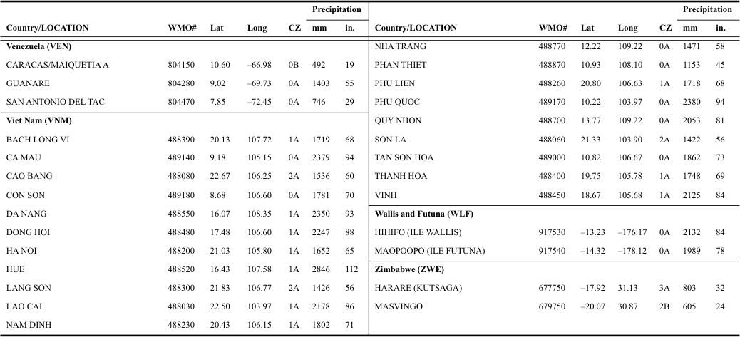
460 ANSI/ASHRAE/IES Standard 90.1-2022 (I-P)
PDF Page 463
SECTION ANNEX1-1 ASHRAE STANDARD 169-2013, SECTION A3: CLIMATE ZONE DEFINITIONS
A3. CLIMATE ZONE DEFINITIONS
To determine the climate zones for locations not listed in this standard, use the following information to determine climate zone numbers and letters.
Determine the thermal climate zone, 0–8, from Table A-3, using the heating and cooling degree-days for the location.
Determine the moisture zone (Marine, Dry or Humid):
a. If monthly average temperature and precipitation data are available, use the Marine, Dry, and Humid
definitions below to determine the moisture zone (C, B, or A). b. If annual average temperature information (including degree-days) and annual precipitation (i.e. annual
mean) are available, use the following to determine the moisture zone:
- If thermal climate zone is 3 and CDD50°F 4500 (CDD10°C 2500), climate zone is Marine (3C).
- If thermal climate zone is 4 and CDD50°F 2700 (CDD10°C 1500), climate zone is Marine (4C).
- If thermal climate zone is 5 and CDD50°F 1800 (CDD10°C 1000), climate zone is Marine (5C).
Use the the third criteria below for determining the Dry/Humid threshold if not Marine (C).
c. If only degree-day information is available, use the following to determine the moisture zone:
- If thermal climate zone is 3 and CDD50°F 4500 (CDD10°C 2500), climate zone is Marine (3C).
- If thermal climate zone is 4 and CDD50°F 2700 (CDD10°C 1500), climate zone is Marine (4C).
- If thermal climate zone is 5 and CDD50°F 1800 (CDD10°C 1000), climate zone is Marine (5C) .
It is not possible to assign Dry/Humid splits in this case.
Marine (C) Zone Definition —Locations meeting all four of the following criteria:
a. Mean temperature of coldest month between 27°F (–3°C) and 65°F (18°C) b. Warmest month mean < 72°F (22°C) c. At least four months with mean temperatures over 50°F (10°C) d. Dry season in summer. The month with the heaviest precipitation in the cold season has at least three
times as much precipitation as the month with the least precipitation in the rest of the year. The cold season is October through March in the Northern Hemisphere and April through September in the Southern Hemisphere.
Dry (B) Definition —Locations meeting the following criteria:
a. Not Marine (C) b. If 70% or more of the precipitation, P, occurs during the high sun period, then the dry/humid threshold is
P < 0.44 × ( T - 7) (I-P) P < 20.0 × ( T + 14) (SI) c. If between 30% and 70% of the precipitation, P, occurs during the high sun period, then the dry/humid
threshold is
P < 0.44 × ( T - 19.5) (I-P) P < 20.0 × ( T + 7) (SI) d. If 30% or less of the precipitation, P, occurs during the high sun period, then the dry/humid threshold is
P < 0.44 × ( T - 32) (I-P) P < 20 × T (SI) where
P = annual precipitation, in. (mm)
T = annual mean temperature, °F (°C)
Summer or high sun period = April through September in the Northern Hemisphere and October through March in the Southern Hemisphere
Winter or cold season = October through March in the Northern Hemisphere and April through September in the Southern Hemisphere
Humid (A) Definition —Locations that are not Marine (C) and not Dry (B)
ANSI/ASHRAE/IES Standard 90.1-2022 (I-P) 461
PDF Page 464
Table Annex1-4 ASHRAE Standard 169-2013, Table A-3: Thermal Climate Zone Definitions
| Thermal Zone | Name | I-P Units | SI Units |
|---|---|---|---|
| 0 | Extremely hot | 10,800 < CDD50°F | 6000 < CDD10°C |
| 1 | Very hot | 9000 < CDD50°F 10,800 | 5000 < CDD10°C 6000 |
| 2 | Hot | 6300 < CDD50°F 9000 | 3500 < CDD10°C 5000 |
| 3 | Warm | CDD50°F 6300 and HDD65°F 3600 | CDD10°C < 3500 and HDD18°C 2000 |
| 4 | Mixed | CDD50°F 6300 and 3600 < HDD65°F 5400 | CDD10°C < 3500 and 2000 < HDD18°C 3000 |
| 5 | Cool | CDD50°F 6300 and 5400 < HDD65°F 7200 | CDD10°C 3500 and 3000 < HDD18°C 4000 |
| 6 | Cold | 7200 < HDD65°F 9000 | 4000 < HDD18°C 5000 |
| 7 | Very cold | 9000 < HDD65°F 12600 | 5000 < HDD18°C 7000 |
| 8 | Subarctic/arctic | 12600 < HDD65°F | 7000 < HDD18°C |
Figure Annex1-2 ASHRAE Standard 169-2013, Figure A-1: Thermal climate zones as a function of heating and cooling degree-days.
462 ANSI/ASHRAE/IES Standard 90.1-2022 (I-P)
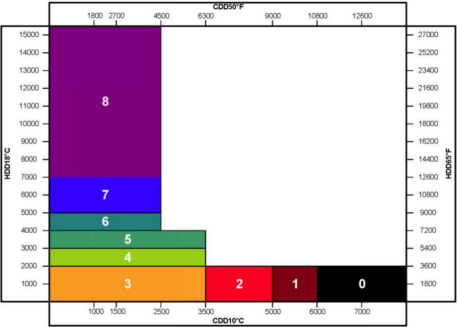
PDF Page 465
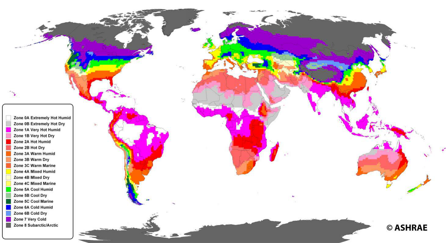
Figure Annex1-3 ASHRAE Standard 169-2013, Figure C-2: World climate zones map.
PDF Page 466
SECTION ANNEX1-2 ASHRAE STANDARD 169-2013, SECTION 4: CLIMATIC DESIGN DATA AND CLIMATE ZONES
4. CLIMATIC DESIGN DATA AND CLIMATE ZONES
Normative Appendix A comprises data for 5564 U.S., Canadian, and international locations. This information generally represents annual and monthly percentiles of occurrence of temperature, various measures of humidity, and wind speed for use in the design of building energy and ventilation systems. These data also include HDD and CDD annual average values and the number of hours between 8 a.m. and 4 p.m. when the dry-bulb temperature is between 55°F and 69°F (13°C and 21°C). A sample of this climatic data is provided in Table A-1 for Atlanta, Georgia, USA. Design conditions for all 5564 locations are located online at the following location:
Table A-4 in Normative Appendix A lists climate zones and other key climatic data for U.S., Canadian, and international locations and includes links to the design conditions.
464 ANSI/ASHRAE/IES Standard 90.1-2022 (I-P)
PDF Page 467
POLICY STATEMENT DEFINING ASHRAE’S CONCERN FOR THE ENVIRONMENTAL IMPACT OF ITS ACTIVITIES
ASHRAE is concerned with the impact of its members’ activities on both the indoor and outdoor environment. ASHRAE’s members will strive to minimize any possible deleterious effect on the indoor and outdoor environment of the systems and components in their responsibility while maximizing the beneficial effects these systems provide, consistent with accepted Standards and the practical state of the art.
ASHRAE’s short-range goal is to ensure that the systems and components within its scope do not impact the indoor and outdoor environment to a greater extent than specified by the Standards and Guidelines as established by itself and other responsible bodies.
As an ongoing goal, ASHRAE will, through its Standards Committee and extensive Technical Committee structure, continue to generate up-to-date Standards and Guidelines where appropriate and adopt, recommend, and promote those new and revised Standards developed by other responsible organizations.
Through its Handbook, appropriate chapters will contain up-to-date Standards and design considerations as the material is systematically revised.
ASHRAE will take the lead with respect to dissemination of environmental information of its primary interest and will seek out and disseminate information from other responsible organizations that is pertinent, as guides to updating Standards and Guidelines.
The effects of the design and selection of equipment and systems will be considered within the scope of the system’s intended use and expected misuse. The disposal of hazardous materials, if any, will also be considered.
ASHRAE’s primary concern for environmental impact will be at the site where equipment within ASHRAE’s scope operates. However, energy source selection and the possible environmental impact due to the energy source and energy transportation will be considered where possible. Recommendations concerning energy source selection should be made by its members.
PDF Page 468

ASHRAE · 180 Technology Parkway · Peachtree Corners, GA 30092 · www.ashrae.org
About ASHRAE
Founded in 1894, ASHRAE is a global professional society committed to serve humanity by advancing the arts and sciences of heating, ventilation, air conditioning, refrigeration, and their allied fields.
As an industry leader in research, standards writing, publishing, certification, and continuing education, ASHRAE and its members are dedicated to promoting a healthy and sustainable built environment for all, through strategic partnerships with organizations in the HVAC&R community and across related industries.
To stay current with this and other ASHRAE Standards and Guidelines, visit www.ashrae.org/standards, and connect on LinkedIn, Facebook, Twitter, and YouTube.
Visit the ASHRAE Bookstore
ASHRAE offers its Standards and Guidelines in print, as immediately downloadable PDFs, and via ASHRAE Digital Collections, which provides online access with automatic updates as well as historical versions of publications. Selected Standards and Guidelines are also offered in redline versions that indicate the changes made between the active Standard or Guideline and its previous edition. For more information, visit the Standards and Guidelines section of the ASHRAE Bookstore at www.ashrae.org/bookstore.
IMPORTANT NOTICES ABOUT THIS STANDARD
To ensure that you have all of the approved addenda, errata, and interpretations for this Standard, visit www.ashrae.org/standards to download them free of charge.
Addenda, errata, and interpretations for ASHRAE Standards and Guidelines are no longer distributed with copies of the Standards and Guidelines. ASHRAE provides these addenda, errata, and interpretations only in electronic form to promote more sustainable use of resources.
Product code: 86327 12/22