Table 12.5.1 Modeling Requirements for Calculating Design Energy Cost and Energy Cost Budget(Continued)
Proposed Design (Column A) Design Energy Cost (DEC)
Budget Building Design (Column B) Energy Cost Budget (ECB)
5. Building Envelope (continued)
For buildings providing verification in accordance with Section 5.9.1.2, the air leakage rate of the building envelope (I75Pa) at a fixed building pressure differential of 75 Pa (0.30 in. of water) shall be 0.45 cfm/ft².
The air leakage rate of the building envelope shall be converted to appropriate units for the simulation program using one of the methods in Section 12.5.3.
The air leakage rate of the building envelope (I75Pa) at a pressure differential of 75 Pa (0.30 of water) shall be 0.35 cfm/ft² of building envelope area and shall be converted to appropriate units for the simulation software using the same method as the proposed design.
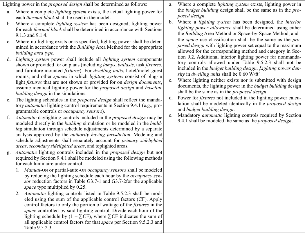
6. Lighting
Lighting power in the proposed design shall be determined as follows:
Where a complete lighting system exists, the actual lighting power for each thermal block shall be used in the model.
Where a complete lighting system has been designed, lighting power for each thermal block shall be determined in accordance with Sections 9.1.3 and 9.1.4.
Where no lighting exists or is specified, lighting power shall be determined in accordance with the Building Area Method for the appropriate building area type.
Lighting system power shall include all lighting system components shown or provided for on plans (including lamps, ballasts, task fixtures, and furniture-mounted fixtures). For dwelling units, hotel/motel guest rooms, and other spaces in which lighting systems consist of plug-in light fixtures that are not shown or provided for on design documents, assume identical lighting power for the proposed design and baseline building design in the simulations.
The lighting schedules in the proposed design shall reflect the mandatory automatic lighting control requirements in Section 9.4.1 (e.g., programmable controls or occupancy sensors).
Automatic daylighting controls included in the proposed design may be modeled directly in the building simulation or be modeled in the building simulation through schedule adjustments determined by a separate analysis approved by the authority having jurisdiction. Modeling and schedule adjustments shall separately account for primary sidelighted areas, secondary sidelighted areas, and toplighted areas.
Automatic lighting controls included in the proposed design but not required by Section 9.4.1 shall be modeled using the following methods for each luminaire under control:
Manual-ON or partial-auto-ON occupancy sensors shall be modeled by reducing the lighting schedule each hour by the occupancy sensor reduction factors in Table G3.7-1 and G3.7-2 for the applicable space type multiplied by 0.25.
Automatic lighting controls listed in Table 9.5.2.3 shall be modeled using the sum of the applicable control factors (CF). Apply control factors to only the portion of wattage of the fixtures in the space controlled by said lighting control. Divide each hour of the lighting schedule by (1 + ∑CF), where ∑CF indicates the sum of all applicable control factors for that space per Section 9.5.2.3 and Table 9.5.2.3.
Where a complete lighting system exists, lighting power in the budget building design shall be the same as in the proposed design.
Where a lighting system has been designed, the interior lighting power allowance shall be determined using either the Building Area Method or Space-by-Space Method, and the space use classification shall be the same as the proposed design with lighting power set equal to the maximum allowed for the corresponding method and category in Section 9.2. Additional interior lighting power for nonmandatory controls allowed under Table 9.5.2.3 shall not be included in the budget building design. Lighting power density in dwelling units shall be 0.60 W/ft².
Where lighting neither exists nor is submitted with design documents, the lighting power in the budget building design shall be the same as in the proposed design.
Power for fixtures not included in the lighting power calculation shall be modeled identically in the proposed design and budget building design.
Mandatory automatic lighting controls required by Section 9.4.1 shall be modeled the same as the proposed design.
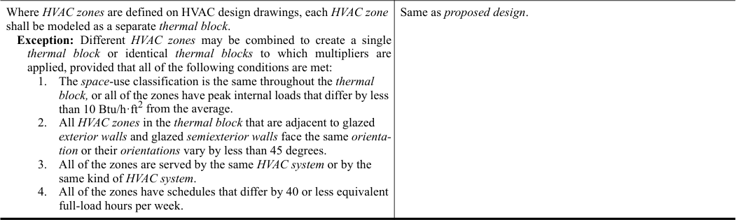
7. Thermal Blocks—HVAC Zones Designed
Where HVAC zones are defined on HVAC design drawings, each HVAC zone shall be modeled as a separate thermal block.
Exception: Different HVAC zones may be combined to create a single thermal block or identical thermal blocks to which multipliers are applied, provided that all of the following conditions are met:
The space-use classification is the same throughout the thermal block, or all of the zones have peak internal loads that differ by less than 10 Btu/h·ft² from the average.
All HVAC zones in the thermal block that are adjacent to glazed exterior walls and glazed semiexterior walls face the same orientation or their orientations vary by less than 45 degrees.
All of the zones are served by the same HVAC system or by the same kind of HVAC system.
All of the zones have schedules that differ by 40 or less equivalent full-load hours per week.