ASHRAE-90.1-2022- - Page 223
Extracted Content
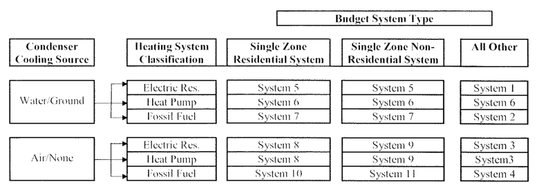
Figure 12.5.2 HVAC systems map.
| Table 12.5.2-1 | Budget System Descriptions | Col3 | Col4 | Col5 |
|---|---|---|---|---|
| System No. | System Type | Fan Control | Cooling Type | Heating Type |
| 1 | VAV with parallel fan-powered boxesa | VAV d | Chilled watere | Electric resistance |
| 2 | VAV with reheatb | VAV d | Chilled watere | Hot-water_fossil fuel_ boilerf |
| 3 | Packaged_VAV_ with parallel fan-powered boxesa | VAV d | Direct expansionc | Electric resistance |
| 4 | Packaged_VAV_ with reheatb | VAV d | Direct expansionc | Hot-water_fossil fuel_ boilerf |
| 5 | Two-pipe fan coil | Single- or two-speed fani,j | Chilled watere | Electric resistance |
| 6 | Water-source heat pump | Single- or two-speed fani,j | Direct expansionc | Electric heat pump and boilerg |
| 7 | Four-pipe fan-coil | Single- or two-speed fani,j | Chilled watere | Hot-water_fossil fuel_ boilerf |
| 8 | Packaged terminal heat pump | Single-speed fani | Direct expansionc | Electric heat pumph |
| 9 | Packaged rooftop heat pump | Single- or two-speed fani,j | Direct expansionc | Electric heat pumph |
| 10 | Packaged terminal air conditioner | Single-speed fani | Direct expansion | Hot-water_fossil fuel_ boilerf |
| 11 | Packaged rooftop air conditioner | Single- or two-speed fani,j | Direct expansion | Fossil fuel furnace |
| a. VAV with Parallel Fan-Powered Boxes: Fans in parallel_VAV_ fan-powered boxes shall be sized for 50% of the peak design flow rate and shall be modeled with 0.35 W/cfm fan power. Minimum volume_set points_ for fan-powered boxes shall be equal to the minimum rate for the_space_ required for_ventilation_ consistent with Section 6.5.2.1, Exception 1(b). Supply air temperature_set point_ shall be constant at the_design condition_ (see Section 12.5.2[g]). b. VAV with Reheat: Minimum volume_set points_ for_VAV_ reheat boxes shall be the larger of the following: (1) the minimum primary outdoor airflow rate required to meet the Simplified Procedure ventilation requirements of ASHRAE Standard 62.1 for the zone or (2) the airflow rate required to comply with applicable codes or accreditation standards, including, but not limited to, pressure relationships or minimum air change rates. The supply air temperature for cooling shall be_reset_ higher by 5°F under the minimum cooling load conditions. c. Direct Expansion: The_fuel_ type for the cooling_system_ shall match that of the cooling_system_ in the_proposed design_. d. VAV: The supply, return, or relief fan motor shall be modeled assuming a variable-speed drive and shall meet the_VAV_ fan part-load performance requirements of Section G3.2.3.15. If the_proposed_ design’s_system_ has a_DDC_ system at the zone level, static pressure_set-point_ reset based on zone requirements in accordance with Section 6.5.3.2.3 shall be modeled. e. Chilled Water: For_systems_ using purchased chilled water, the chillers are not explicitly modeled, and chilled-water costs shall be based as determined in Section 12.4.3. Otherwise, the_budget_ building design’s chiller plant shall be modeled with chillers having the number as indicated in Table 12.5.2-2 as a function of_budget building design_ chiller plant load and type as indicated in Table 12.5.2-3 as a function of individual chiller load. Where chiller_fuel_ source is mixed, the_system_ in the_budget building design_ shall have chillers with the same_fuel_ types and with capacities having the same proportional capacity as the_proposed design_’s chillers for each_fuel_ type. Chilled-water supply temperature shall be modeled at 44°F design supply temperature and 56°F return temperature.Piping losses shall not be modeled in either_building_ model. Chilled-water supply water temperature shall be_reset_ in accordance with Section 6.5.4.4.Pump system power for each pumping_system_ shall be the same as for the_proposed design_; if the_proposed design_ has no chilled-water_pumps_, the_budget building design_ pump power shall be 22 W/gpm (equal to a_pump_ oper- ating against a 75 ft head, 65% combined impeller and motor_efficiency_). The chilled-water_system_ shall be modeled as primary-only variable flow with flow maintained at the design rate through each chiller using a bypass. Chilled-water_pumps_ shall be modeled as riding the_pump_ curve or with variable-speed drives when required in Section 6.5.4.2. The heat-rejection device shall be an open-circuit axial-fan cooling tower with variable-speed fan control, if required in Section 6.5.5, and shall meet the performance requirements of Table 6.8.1-7. Condenser water design supply temperature shall be calculated using the cooling tower approach to the 0.4% evaporation design wet-bulb temperature as generated by the formula below, with a design temperature rise of 10°F: Approach_10°FRange_ = 25.72 – (0.24 × WB) where WB is the 0.4%evaporation design wet-bulb temperature in °F, valid for wet bulbs from 55°F to 90°F. The tower shall be controlled to maintain a cooling tower leaving water temperature, where weather permits, per Table 12.5.2-4, floating up to the design leaving water temperature for the cooling tower.Pump system power for each pumping_system_ shall be the same as the_proposed design_; if the_proposed design_ has no condenser water_pumps_, the_budget building design_ pump power shall be 19 W/gpm (equal to a_pump_ operating against a 60 ft head, 60% combined impeller and motor_efficiency_). Each chiller shall be modeled with separate condenser water and chilled-water_pumps_ interlocked to operate with the associated chiller. f. Fossil Fuel Boiler: For_systems_ using purchased hot water or steam, the_boilers_ are not explicitly modeled and hot-water or steam costs shall be based on actual utility rates. Otherwise, the_boiler_ plant shall use the same_fuel_ as the_proposed design_ and shall be natural draft. The_budget building design_ boiler plant shall be modeled with a single_boiler_ if the_budget building design_ plant load is 600,000 Btu/h or less and with two equally sized_boilers_ for plant capacities exceeding 600,000 Btu/h.Boilers shall be staged as required by the load. For_boiler systems_ meeting the requirements of Section 6.5.4.8, the hot-water supply temperature shall be modeled at 170°F design supply temperature and 120°F return temperature. For all other boiler systems, the hot-water supply tempera- ture shall be modeled at 180°F design supply temperature and 130°F return temperature.Piping losses shall not be modeled in either_building_ model. Hot-water supply water temperature shall be_reset_ in accordance with Section 6.5.4.4.Pump system power for each pumping_system_ shall be the same as for the_proposed design_; if the_proposed design_ has no hot-water_pumps_, the_budget_ building design pump power shall be 19 W/gpm (equal to a_pump_ operating against a 60 ft head, 60% combined impeller and motor_efficiency_). The hot-water_system_ shall be modeled as primary- only with continuous variable flow. Hot-water_pumps_ shall be modeled as riding the_pump_ curve or with variable-speed drives when required by Section 6.5.4.2. g. Electric Heat Pump and Boiler: Water-source heat pumps shall be connected to a common heat-pump water loop controlled to maintain temperatures between 60°F and 90°F. Heat rejection from the loop shall be provided by a closed-circuit axial-fan evaporative fluid cooler with fan-speed control as required in Section 6.5.5.2. Heat addition to the loop shall be provided by a_boiler_ that uses the same_fuel_ as the_proposed design_ and shall be natural draft. If no_boilers_ exist in the_proposed design_, the budget_building_ boilers shall be_fossil fuel_. The_budget building design_ boiler plant shall be modeled with a single_boiler_ if the_budget building design_ plant load is 600,000 Btu/h or less and with two equally sized_boilers_ for plant capacities exceeding 600,000 Btu/h.Boilers shall be staged as required by the load.Piping losses shall not be modeled in either_building_ model.Pump system power shall be the same as for the_proposed design_; if the_proposed design_ has no_pumps_, the_budget building design_ pump power shall be 22 W/gpm, which is equal to a_pump_ operating against a 75 ft head, with a 65% combined impeller and motor_efficiency_. Loop flow shall be variable with flow shutoff at each heat pump when its compressor cyclesOFF as required by Section 6.5.4.5 Loop_pumps_ shall be modeled as riding the_pump_ curve or with variable-speed drives when required by Section 6.5.4.2. h. Electric Heat Pump: Electric air source heat pumps shall be modeled with electric auxiliary heat. The_system_ shall be controlled with a multistage_space_ thermostat and an_outdoor air_ thermostat wired to energize auxiliary heat only on the last_thermostat_ stage and when_outdoor air_ temperature is less than 40°F. i. **Fan System Operation:**Fans shall be controlled in the same manner as in the_proposed design_; i.e., fan operation whenever the_space_ is occupied or fan operation cycledON calls for heating and cooling. j. **Fan Speed Control:**Fans shall operate as one or two speed as required by Section 6.5.3.2, regardless of the fan speed control used in the_proposed_ design. | a. VAV with Parallel Fan-Powered Boxes: Fans in parallel_VAV_ fan-powered boxes shall be sized for 50% of the peak design flow rate and shall be modeled with 0.35 W/cfm fan power. Minimum volume_set points_ for fan-powered boxes shall be equal to the minimum rate for the_space_ required for_ventilation_ consistent with Section 6.5.2.1, Exception 1(b). Supply air temperature_set point_ shall be constant at the_design condition_ (see Section 12.5.2[g]). b. VAV with Reheat: Minimum volume_set points_ for_VAV_ reheat boxes shall be the larger of the following: (1) the minimum primary outdoor airflow rate required to meet the Simplified Procedure ventilation requirements of ASHRAE Standard 62.1 for the zone or (2) the airflow rate required to comply with applicable codes or accreditation standards, including, but not limited to, pressure relationships or minimum air change rates. The supply air temperature for cooling shall be_reset_ higher by 5°F under the minimum cooling load conditions. c. Direct Expansion: The_fuel_ type for the cooling_system_ shall match that of the cooling_system_ in the_proposed design_. d. VAV: The supply, return, or relief fan motor shall be modeled assuming a variable-speed drive and shall meet the_VAV_ fan part-load performance requirements of Section G3.2.3.15. If the_proposed_ design’s_system_ has a_DDC_ system at the zone level, static pressure_set-point_ reset based on zone requirements in accordance with Section 6.5.3.2.3 shall be modeled. e. Chilled Water: For_systems_ using purchased chilled water, the chillers are not explicitly modeled, and chilled-water costs shall be based as determined in Section 12.4.3. Otherwise, the_budget_ building design’s chiller plant shall be modeled with chillers having the number as indicated in Table 12.5.2-2 as a function of_budget building design_ chiller plant load and type as indicated in Table 12.5.2-3 as a function of individual chiller load. Where chiller_fuel_ source is mixed, the_system_ in the_budget building design_ shall have chillers with the same_fuel_ types and with capacities having the same proportional capacity as the_proposed design_’s chillers for each_fuel_ type. Chilled-water supply temperature shall be modeled at 44°F design supply temperature and 56°F return temperature.Piping losses shall not be modeled in either_building_ model. Chilled-water supply water temperature shall be_reset_ in accordance with Section 6.5.4.4.Pump system power for each pumping_system_ shall be the same as for the_proposed design_; if the_proposed design_ has no chilled-water_pumps_, the_budget building design_ pump power shall be 22 W/gpm (equal to a_pump_ oper- ating against a 75 ft head, 65% combined impeller and motor_efficiency_). The chilled-water_system_ shall be modeled as primary-only variable flow with flow maintained at the design rate through each chiller using a bypass. Chilled-water_pumps_ shall be modeled as riding the_pump_ curve or with variable-speed drives when required in Section 6.5.4.2. The heat-rejection device shall be an open-circuit axial-fan cooling tower with variable-speed fan control, if required in Section 6.5.5, and shall meet the performance requirements of Table 6.8.1-7. Condenser water design supply temperature shall be calculated using the cooling tower approach to the 0.4% evaporation design wet-bulb temperature as generated by the formula below, with a design temperature rise of 10°F: Approach_10°FRange_ = 25.72 – (0.24 × WB) where WB is the 0.4%evaporation design wet-bulb temperature in °F, valid for wet bulbs from 55°F to 90°F. The tower shall be controlled to maintain a cooling tower leaving water temperature, where weather permits, per Table 12.5.2-4, floating up to the design leaving water temperature for the cooling tower.Pump system power for each pumping_system_ shall be the same as the_proposed design_; if the_proposed design_ has no condenser water_pumps_, the_budget building design_ pump power shall be 19 W/gpm (equal to a_pump_ operating against a 60 ft head, 60% combined impeller and motor_efficiency_). Each chiller shall be modeled with separate condenser water and chilled-water_pumps_ interlocked to operate with the associated chiller. f. Fossil Fuel Boiler: For_systems_ using purchased hot water or steam, the_boilers_ are not explicitly modeled and hot-water or steam costs shall be based on actual utility rates. Otherwise, the_boiler_ plant shall use the same_fuel_ as the_proposed design_ and shall be natural draft. The_budget building design_ boiler plant shall be modeled with a single_boiler_ if the_budget building design_ plant load is 600,000 Btu/h or less and with two equally sized_boilers_ for plant capacities exceeding 600,000 Btu/h.Boilers shall be staged as required by the load. For_boiler systems_ meeting the requirements of Section 6.5.4.8, the hot-water supply temperature shall be modeled at 170°F design supply temperature and 120°F return temperature. For all other boiler systems, the hot-water supply tempera- ture shall be modeled at 180°F design supply temperature and 130°F return temperature.Piping losses shall not be modeled in either_building_ model. Hot-water supply water temperature shall be_reset_ in accordance with Section 6.5.4.4.Pump system power for each pumping_system_ shall be the same as for the_proposed design_; if the_proposed design_ has no hot-water_pumps_, the_budget_ building design pump power shall be 19 W/gpm (equal to a_pump_ operating against a 60 ft head, 60% combined impeller and motor_efficiency_). The hot-water_system_ shall be modeled as primary- only with continuous variable flow. Hot-water_pumps_ shall be modeled as riding the_pump_ curve or with variable-speed drives when required by Section 6.5.4.2. g. Electric Heat Pump and Boiler: Water-source heat pumps shall be connected to a common heat-pump water loop controlled to maintain temperatures between 60°F and 90°F. Heat rejection from the loop shall be provided by a closed-circuit axial-fan evaporative fluid cooler with fan-speed control as required in Section 6.5.5.2. Heat addition to the loop shall be provided by a_boiler_ that uses the same_fuel_ as the_proposed design_ and shall be natural draft. If no_boilers_ exist in the_proposed design_, the budget_building_ boilers shall be_fossil fuel_. The_budget building design_ boiler plant shall be modeled with a single_boiler_ if the_budget building design_ plant load is 600,000 Btu/h or less and with two equally sized_boilers_ for plant capacities exceeding 600,000 Btu/h.Boilers shall be staged as required by the load.Piping losses shall not be modeled in either_building_ model.Pump system power shall be the same as for the_proposed design_; if the_proposed design_ has no_pumps_, the_budget building design_ pump power shall be 22 W/gpm, which is equal to a_pump_ operating against a 75 ft head, with a 65% combined impeller and motor_efficiency_. Loop flow shall be variable with flow shutoff at each heat pump when its compressor cyclesOFF as required by Section 6.5.4.5 Loop_pumps_ shall be modeled as riding the_pump_ curve or with variable-speed drives when required by Section 6.5.4.2. h. Electric Heat Pump: Electric air source heat pumps shall be modeled with electric auxiliary heat. The_system_ shall be controlled with a multistage_space_ thermostat and an_outdoor air_ thermostat wired to energize auxiliary heat only on the last_thermostat_ stage and when_outdoor air_ temperature is less than 40°F. i. **Fan System Operation:**Fans shall be controlled in the same manner as in the_proposed design_; i.e., fan operation whenever the_space_ is occupied or fan operation cycledON calls for heating and cooling. j. **Fan Speed Control:**Fans shall operate as one or two speed as required by Section 6.5.3.2, regardless of the fan speed control used in the_proposed_ design. | a. VAV with Parallel Fan-Powered Boxes: Fans in parallel_VAV_ fan-powered boxes shall be sized for 50% of the peak design flow rate and shall be modeled with 0.35 W/cfm fan power. Minimum volume_set points_ for fan-powered boxes shall be equal to the minimum rate for the_space_ required for_ventilation_ consistent with Section 6.5.2.1, Exception 1(b). Supply air temperature_set point_ shall be constant at the_design condition_ (see Section 12.5.2[g]). b. VAV with Reheat: Minimum volume_set points_ for_VAV_ reheat boxes shall be the larger of the following: (1) the minimum primary outdoor airflow rate required to meet the Simplified Procedure ventilation requirements of ASHRAE Standard 62.1 for the zone or (2) the airflow rate required to comply with applicable codes or accreditation standards, including, but not limited to, pressure relationships or minimum air change rates. The supply air temperature for cooling shall be_reset_ higher by 5°F under the minimum cooling load conditions. c. Direct Expansion: The_fuel_ type for the cooling_system_ shall match that of the cooling_system_ in the_proposed design_. d. VAV: The supply, return, or relief fan motor shall be modeled assuming a variable-speed drive and shall meet the_VAV_ fan part-load performance requirements of Section G3.2.3.15. If the_proposed_ design’s_system_ has a_DDC_ system at the zone level, static pressure_set-point_ reset based on zone requirements in accordance with Section 6.5.3.2.3 shall be modeled. e. Chilled Water: For_systems_ using purchased chilled water, the chillers are not explicitly modeled, and chilled-water costs shall be based as determined in Section 12.4.3. Otherwise, the_budget_ building design’s chiller plant shall be modeled with chillers having the number as indicated in Table 12.5.2-2 as a function of_budget building design_ chiller plant load and type as indicated in Table 12.5.2-3 as a function of individual chiller load. Where chiller_fuel_ source is mixed, the_system_ in the_budget building design_ shall have chillers with the same_fuel_ types and with capacities having the same proportional capacity as the_proposed design_’s chillers for each_fuel_ type. Chilled-water supply temperature shall be modeled at 44°F design supply temperature and 56°F return temperature.Piping losses shall not be modeled in either_building_ model. Chilled-water supply water temperature shall be_reset_ in accordance with Section 6.5.4.4.Pump system power for each pumping_system_ shall be the same as for the_proposed design_; if the_proposed design_ has no chilled-water_pumps_, the_budget building design_ pump power shall be 22 W/gpm (equal to a_pump_ oper- ating against a 75 ft head, 65% combined impeller and motor_efficiency_). The chilled-water_system_ shall be modeled as primary-only variable flow with flow maintained at the design rate through each chiller using a bypass. Chilled-water_pumps_ shall be modeled as riding the_pump_ curve or with variable-speed drives when required in Section 6.5.4.2. The heat-rejection device shall be an open-circuit axial-fan cooling tower with variable-speed fan control, if required in Section 6.5.5, and shall meet the performance requirements of Table 6.8.1-7. Condenser water design supply temperature shall be calculated using the cooling tower approach to the 0.4% evaporation design wet-bulb temperature as generated by the formula below, with a design temperature rise of 10°F: Approach_10°FRange_ = 25.72 – (0.24 × WB) where WB is the 0.4%evaporation design wet-bulb temperature in °F, valid for wet bulbs from 55°F to 90°F. The tower shall be controlled to maintain a cooling tower leaving water temperature, where weather permits, per Table 12.5.2-4, floating up to the design leaving water temperature for the cooling tower.Pump system power for each pumping_system_ shall be the same as the_proposed design_; if the_proposed design_ has no condenser water_pumps_, the_budget building design_ pump power shall be 19 W/gpm (equal to a_pump_ operating against a 60 ft head, 60% combined impeller and motor_efficiency_). Each chiller shall be modeled with separate condenser water and chilled-water_pumps_ interlocked to operate with the associated chiller. f. Fossil Fuel Boiler: For_systems_ using purchased hot water or steam, the_boilers_ are not explicitly modeled and hot-water or steam costs shall be based on actual utility rates. Otherwise, the_boiler_ plant shall use the same_fuel_ as the_proposed design_ and shall be natural draft. The_budget building design_ boiler plant shall be modeled with a single_boiler_ if the_budget building design_ plant load is 600,000 Btu/h or less and with two equally sized_boilers_ for plant capacities exceeding 600,000 Btu/h.Boilers shall be staged as required by the load. For_boiler systems_ meeting the requirements of Section 6.5.4.8, the hot-water supply temperature shall be modeled at 170°F design supply temperature and 120°F return temperature. For all other boiler systems, the hot-water supply tempera- ture shall be modeled at 180°F design supply temperature and 130°F return temperature.Piping losses shall not be modeled in either_building_ model. Hot-water supply water temperature shall be_reset_ in accordance with Section 6.5.4.4.Pump system power for each pumping_system_ shall be the same as for the_proposed design_; if the_proposed design_ has no hot-water_pumps_, the_budget_ building design pump power shall be 19 W/gpm (equal to a_pump_ operating against a 60 ft head, 60% combined impeller and motor_efficiency_). The hot-water_system_ shall be modeled as primary- only with continuous variable flow. Hot-water_pumps_ shall be modeled as riding the_pump_ curve or with variable-speed drives when required by Section 6.5.4.2. g. Electric Heat Pump and Boiler: Water-source heat pumps shall be connected to a common heat-pump water loop controlled to maintain temperatures between 60°F and 90°F. Heat rejection from the loop shall be provided by a closed-circuit axial-fan evaporative fluid cooler with fan-speed control as required in Section 6.5.5.2. Heat addition to the loop shall be provided by a_boiler_ that uses the same_fuel_ as the_proposed design_ and shall be natural draft. If no_boilers_ exist in the_proposed design_, the budget_building_ boilers shall be_fossil fuel_. The_budget building design_ boiler plant shall be modeled with a single_boiler_ if the_budget building design_ plant load is 600,000 Btu/h or less and with two equally sized_boilers_ for plant capacities exceeding 600,000 Btu/h.Boilers shall be staged as required by the load.Piping losses shall not be modeled in either_building_ model.Pump system power shall be the same as for the_proposed design_; if the_proposed design_ has no_pumps_, the_budget building design_ pump power shall be 22 W/gpm, which is equal to a_pump_ operating against a 75 ft head, with a 65% combined impeller and motor_efficiency_. Loop flow shall be variable with flow shutoff at each heat pump when its compressor cyclesOFF as required by Section 6.5.4.5 Loop_pumps_ shall be modeled as riding the_pump_ curve or with variable-speed drives when required by Section 6.5.4.2. h. Electric Heat Pump: Electric air source heat pumps shall be modeled with electric auxiliary heat. The_system_ shall be controlled with a multistage_space_ thermostat and an_outdoor air_ thermostat wired to energize auxiliary heat only on the last_thermostat_ stage and when_outdoor air_ temperature is less than 40°F. i. **Fan System Operation:**Fans shall be controlled in the same manner as in the_proposed design_; i.e., fan operation whenever the_space_ is occupied or fan operation cycledON calls for heating and cooling. j. **Fan Speed Control:**Fans shall operate as one or two speed as required by Section 6.5.3.2, regardless of the fan speed control used in the_proposed_ design. | a. VAV with Parallel Fan-Powered Boxes: Fans in parallel_VAV_ fan-powered boxes shall be sized for 50% of the peak design flow rate and shall be modeled with 0.35 W/cfm fan power. Minimum volume_set points_ for fan-powered boxes shall be equal to the minimum rate for the_space_ required for_ventilation_ consistent with Section 6.5.2.1, Exception 1(b). Supply air temperature_set point_ shall be constant at the_design condition_ (see Section 12.5.2[g]). b. VAV with Reheat: Minimum volume_set points_ for_VAV_ reheat boxes shall be the larger of the following: (1) the minimum primary outdoor airflow rate required to meet the Simplified Procedure ventilation requirements of ASHRAE Standard 62.1 for the zone or (2) the airflow rate required to comply with applicable codes or accreditation standards, including, but not limited to, pressure relationships or minimum air change rates. The supply air temperature for cooling shall be_reset_ higher by 5°F under the minimum cooling load conditions. c. Direct Expansion: The_fuel_ type for the cooling_system_ shall match that of the cooling_system_ in the_proposed design_. d. VAV: The supply, return, or relief fan motor shall be modeled assuming a variable-speed drive and shall meet the_VAV_ fan part-load performance requirements of Section G3.2.3.15. If the_proposed_ design’s_system_ has a_DDC_ system at the zone level, static pressure_set-point_ reset based on zone requirements in accordance with Section 6.5.3.2.3 shall be modeled. e. Chilled Water: For_systems_ using purchased chilled water, the chillers are not explicitly modeled, and chilled-water costs shall be based as determined in Section 12.4.3. Otherwise, the_budget_ building design’s chiller plant shall be modeled with chillers having the number as indicated in Table 12.5.2-2 as a function of_budget building design_ chiller plant load and type as indicated in Table 12.5.2-3 as a function of individual chiller load. Where chiller_fuel_ source is mixed, the_system_ in the_budget building design_ shall have chillers with the same_fuel_ types and with capacities having the same proportional capacity as the_proposed design_’s chillers for each_fuel_ type. Chilled-water supply temperature shall be modeled at 44°F design supply temperature and 56°F return temperature.Piping losses shall not be modeled in either_building_ model. Chilled-water supply water temperature shall be_reset_ in accordance with Section 6.5.4.4.Pump system power for each pumping_system_ shall be the same as for the_proposed design_; if the_proposed design_ has no chilled-water_pumps_, the_budget building design_ pump power shall be 22 W/gpm (equal to a_pump_ oper- ating against a 75 ft head, 65% combined impeller and motor_efficiency_). The chilled-water_system_ shall be modeled as primary-only variable flow with flow maintained at the design rate through each chiller using a bypass. Chilled-water_pumps_ shall be modeled as riding the_pump_ curve or with variable-speed drives when required in Section 6.5.4.2. The heat-rejection device shall be an open-circuit axial-fan cooling tower with variable-speed fan control, if required in Section 6.5.5, and shall meet the performance requirements of Table 6.8.1-7. Condenser water design supply temperature shall be calculated using the cooling tower approach to the 0.4% evaporation design wet-bulb temperature as generated by the formula below, with a design temperature rise of 10°F: Approach_10°FRange_ = 25.72 – (0.24 × WB) where WB is the 0.4%evaporation design wet-bulb temperature in °F, valid for wet bulbs from 55°F to 90°F. The tower shall be controlled to maintain a cooling tower leaving water temperature, where weather permits, per Table 12.5.2-4, floating up to the design leaving water temperature for the cooling tower.Pump system power for each pumping_system_ shall be the same as the_proposed design_; if the_proposed design_ has no condenser water_pumps_, the_budget building design_ pump power shall be 19 W/gpm (equal to a_pump_ operating against a 60 ft head, 60% combined impeller and motor_efficiency_). Each chiller shall be modeled with separate condenser water and chilled-water_pumps_ interlocked to operate with the associated chiller. f. Fossil Fuel Boiler: For_systems_ using purchased hot water or steam, the_boilers_ are not explicitly modeled and hot-water or steam costs shall be based on actual utility rates. Otherwise, the_boiler_ plant shall use the same_fuel_ as the_proposed design_ and shall be natural draft. The_budget building design_ boiler plant shall be modeled with a single_boiler_ if the_budget building design_ plant load is 600,000 Btu/h or less and with two equally sized_boilers_ for plant capacities exceeding 600,000 Btu/h.Boilers shall be staged as required by the load. For_boiler systems_ meeting the requirements of Section 6.5.4.8, the hot-water supply temperature shall be modeled at 170°F design supply temperature and 120°F return temperature. For all other boiler systems, the hot-water supply tempera- ture shall be modeled at 180°F design supply temperature and 130°F return temperature.Piping losses shall not be modeled in either_building_ model. Hot-water supply water temperature shall be_reset_ in accordance with Section 6.5.4.4.Pump system power for each pumping_system_ shall be the same as for the_proposed design_; if the_proposed design_ has no hot-water_pumps_, the_budget_ building design pump power shall be 19 W/gpm (equal to a_pump_ operating against a 60 ft head, 60% combined impeller and motor_efficiency_). The hot-water_system_ shall be modeled as primary- only with continuous variable flow. Hot-water_pumps_ shall be modeled as riding the_pump_ curve or with variable-speed drives when required by Section 6.5.4.2. g. Electric Heat Pump and Boiler: Water-source heat pumps shall be connected to a common heat-pump water loop controlled to maintain temperatures between 60°F and 90°F. Heat rejection from the loop shall be provided by a closed-circuit axial-fan evaporative fluid cooler with fan-speed control as required in Section 6.5.5.2. Heat addition to the loop shall be provided by a_boiler_ that uses the same_fuel_ as the_proposed design_ and shall be natural draft. If no_boilers_ exist in the_proposed design_, the budget_building_ boilers shall be_fossil fuel_. The_budget building design_ boiler plant shall be modeled with a single_boiler_ if the_budget building design_ plant load is 600,000 Btu/h or less and with two equally sized_boilers_ for plant capacities exceeding 600,000 Btu/h.Boilers shall be staged as required by the load.Piping losses shall not be modeled in either_building_ model.Pump system power shall be the same as for the_proposed design_; if the_proposed design_ has no_pumps_, the_budget building design_ pump power shall be 22 W/gpm, which is equal to a_pump_ operating against a 75 ft head, with a 65% combined impeller and motor_efficiency_. Loop flow shall be variable with flow shutoff at each heat pump when its compressor cyclesOFF as required by Section 6.5.4.5 Loop_pumps_ shall be modeled as riding the_pump_ curve or with variable-speed drives when required by Section 6.5.4.2. h. Electric Heat Pump: Electric air source heat pumps shall be modeled with electric auxiliary heat. The_system_ shall be controlled with a multistage_space_ thermostat and an_outdoor air_ thermostat wired to energize auxiliary heat only on the last_thermostat_ stage and when_outdoor air_ temperature is less than 40°F. i. **Fan System Operation:**Fans shall be controlled in the same manner as in the_proposed design_; i.e., fan operation whenever the_space_ is occupied or fan operation cycledON calls for heating and cooling. j. **Fan Speed Control:**Fans shall operate as one or two speed as required by Section 6.5.3.2, regardless of the fan speed control used in the_proposed_ design. | a. VAV with Parallel Fan-Powered Boxes: Fans in parallel_VAV_ fan-powered boxes shall be sized for 50% of the peak design flow rate and shall be modeled with 0.35 W/cfm fan power. Minimum volume_set points_ for fan-powered boxes shall be equal to the minimum rate for the_space_ required for_ventilation_ consistent with Section 6.5.2.1, Exception 1(b). Supply air temperature_set point_ shall be constant at the_design condition_ (see Section 12.5.2[g]). b. VAV with Reheat: Minimum volume_set points_ for_VAV_ reheat boxes shall be the larger of the following: (1) the minimum primary outdoor airflow rate required to meet the Simplified Procedure ventilation requirements of ASHRAE Standard 62.1 for the zone or (2) the airflow rate required to comply with applicable codes or accreditation standards, including, but not limited to, pressure relationships or minimum air change rates. The supply air temperature for cooling shall be_reset_ higher by 5°F under the minimum cooling load conditions. c. Direct Expansion: The_fuel_ type for the cooling_system_ shall match that of the cooling_system_ in the_proposed design_. d. VAV: The supply, return, or relief fan motor shall be modeled assuming a variable-speed drive and shall meet the_VAV_ fan part-load performance requirements of Section G3.2.3.15. If the_proposed_ design’s_system_ has a_DDC_ system at the zone level, static pressure_set-point_ reset based on zone requirements in accordance with Section 6.5.3.2.3 shall be modeled. e. Chilled Water: For_systems_ using purchased chilled water, the chillers are not explicitly modeled, and chilled-water costs shall be based as determined in Section 12.4.3. Otherwise, the_budget_ building design’s chiller plant shall be modeled with chillers having the number as indicated in Table 12.5.2-2 as a function of_budget building design_ chiller plant load and type as indicated in Table 12.5.2-3 as a function of individual chiller load. Where chiller_fuel_ source is mixed, the_system_ in the_budget building design_ shall have chillers with the same_fuel_ types and with capacities having the same proportional capacity as the_proposed design_’s chillers for each_fuel_ type. Chilled-water supply temperature shall be modeled at 44°F design supply temperature and 56°F return temperature.Piping losses shall not be modeled in either_building_ model. Chilled-water supply water temperature shall be_reset_ in accordance with Section 6.5.4.4.Pump system power for each pumping_system_ shall be the same as for the_proposed design_; if the_proposed design_ has no chilled-water_pumps_, the_budget building design_ pump power shall be 22 W/gpm (equal to a_pump_ oper- ating against a 75 ft head, 65% combined impeller and motor_efficiency_). The chilled-water_system_ shall be modeled as primary-only variable flow with flow maintained at the design rate through each chiller using a bypass. Chilled-water_pumps_ shall be modeled as riding the_pump_ curve or with variable-speed drives when required in Section 6.5.4.2. The heat-rejection device shall be an open-circuit axial-fan cooling tower with variable-speed fan control, if required in Section 6.5.5, and shall meet the performance requirements of Table 6.8.1-7. Condenser water design supply temperature shall be calculated using the cooling tower approach to the 0.4% evaporation design wet-bulb temperature as generated by the formula below, with a design temperature rise of 10°F: Approach_10°FRange_ = 25.72 – (0.24 × WB) where WB is the 0.4%evaporation design wet-bulb temperature in °F, valid for wet bulbs from 55°F to 90°F. The tower shall be controlled to maintain a cooling tower leaving water temperature, where weather permits, per Table 12.5.2-4, floating up to the design leaving water temperature for the cooling tower.Pump system power for each pumping_system_ shall be the same as the_proposed design_; if the_proposed design_ has no condenser water_pumps_, the_budget building design_ pump power shall be 19 W/gpm (equal to a_pump_ operating against a 60 ft head, 60% combined impeller and motor_efficiency_). Each chiller shall be modeled with separate condenser water and chilled-water_pumps_ interlocked to operate with the associated chiller. f. Fossil Fuel Boiler: For_systems_ using purchased hot water or steam, the_boilers_ are not explicitly modeled and hot-water or steam costs shall be based on actual utility rates. Otherwise, the_boiler_ plant shall use the same_fuel_ as the_proposed design_ and shall be natural draft. The_budget building design_ boiler plant shall be modeled with a single_boiler_ if the_budget building design_ plant load is 600,000 Btu/h or less and with two equally sized_boilers_ for plant capacities exceeding 600,000 Btu/h.Boilers shall be staged as required by the load. For_boiler systems_ meeting the requirements of Section 6.5.4.8, the hot-water supply temperature shall be modeled at 170°F design supply temperature and 120°F return temperature. For all other boiler systems, the hot-water supply tempera- ture shall be modeled at 180°F design supply temperature and 130°F return temperature.Piping losses shall not be modeled in either_building_ model. Hot-water supply water temperature shall be_reset_ in accordance with Section 6.5.4.4.Pump system power for each pumping_system_ shall be the same as for the_proposed design_; if the_proposed design_ has no hot-water_pumps_, the_budget_ building design pump power shall be 19 W/gpm (equal to a_pump_ operating against a 60 ft head, 60% combined impeller and motor_efficiency_). The hot-water_system_ shall be modeled as primary- only with continuous variable flow. Hot-water_pumps_ shall be modeled as riding the_pump_ curve or with variable-speed drives when required by Section 6.5.4.2. g. Electric Heat Pump and Boiler: Water-source heat pumps shall be connected to a common heat-pump water loop controlled to maintain temperatures between 60°F and 90°F. Heat rejection from the loop shall be provided by a closed-circuit axial-fan evaporative fluid cooler with fan-speed control as required in Section 6.5.5.2. Heat addition to the loop shall be provided by a_boiler_ that uses the same_fuel_ as the_proposed design_ and shall be natural draft. If no_boilers_ exist in the_proposed design_, the budget_building_ boilers shall be_fossil fuel_. The_budget building design_ boiler plant shall be modeled with a single_boiler_ if the_budget building design_ plant load is 600,000 Btu/h or less and with two equally sized_boilers_ for plant capacities exceeding 600,000 Btu/h.Boilers shall be staged as required by the load.Piping losses shall not be modeled in either_building_ model.Pump system power shall be the same as for the_proposed design_; if the_proposed design_ has no_pumps_, the_budget building design_ pump power shall be 22 W/gpm, which is equal to a_pump_ operating against a 75 ft head, with a 65% combined impeller and motor_efficiency_. Loop flow shall be variable with flow shutoff at each heat pump when its compressor cyclesOFF as required by Section 6.5.4.5 Loop_pumps_ shall be modeled as riding the_pump_ curve or with variable-speed drives when required by Section 6.5.4.2. h. Electric Heat Pump: Electric air source heat pumps shall be modeled with electric auxiliary heat. The_system_ shall be controlled with a multistage_space_ thermostat and an_outdoor air_ thermostat wired to energize auxiliary heat only on the last_thermostat_ stage and when_outdoor air_ temperature is less than 40°F. i. **Fan System Operation:**Fans shall be controlled in the same manner as in the_proposed design_; i.e., fan operation whenever the_space_ is occupied or fan operation cycledON calls for heating and cooling. j. **Fan Speed Control:**Fans shall operate as one or two speed as required by Section 6.5.3.2, regardless of the fan speed control used in the_proposed_ design. |
ANSI/ASHRAE/IES Standard 90.1-2022 (I-P) 221