ASHRAE-90.1-2022- - Page 268
Extracted Content
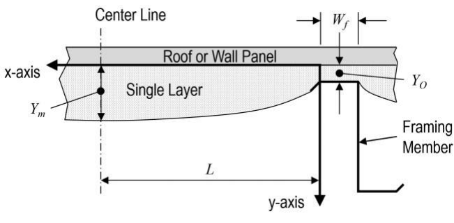
Figure A9.4.6.1 Geometry of single-layer fiberglass batt.
where X = distance from edge of purlin or girt, ft Y = distance from edge of roof panel or wall panel, ft L = length from edge of purlin or girt to centerline of cavity, ft wf = width of purlin or girt flange, ft Yo = distance between purlin or girt and the roof panel or wall panel, ft Ym = distance from edge of roof panel or wall panel at the cavity centerline, ft
d. For calculation purposes, the effective R-value for insulation installed in cavities in steel-framed walls
shall be taken from Table A9.2-2.
A9.4.4 Building Material Thermal Properties. R-values for building materials shall be taken from Table A9.4.4-1. Concrete block R-values shall be calculated using the isothermal planes method or a twodimensional calculation program, thermal conductivities from Table A9.4.2-2, and dimensions from ASTM C90. The parallel path calculation method is not acceptable.
Exception to A9.4.4: R-values for building materials or thermal conductivities determined from testing
in accordance with Section A9.3.
A9.4.5 Building Material Heat Capacities. The HC of assemblies shall be calculated using published values for the unit weight and specific heat of all building material components that make up the assembly.
A9.4.6 Metal Building U-Factor Equations. The calculation procedures in this section shall use a fixed purlin and girt spacing of 60 in., and the results shall be permitted to be used in accordance with Sections A2.3.3 and A3.2.3. For single-layer metal building roof and single-layer compressed metal building wall systems, the calculation procedure outlined in Section A9.4.6.1 shall be used to calculate the assembly U- factor . For double-layer metal building roof systems, the calculation procedure outlined in Section A9.4.6.2 shall be used to calculate the assembly U-factor . For single-layer in cavity and double-layer metal build- ing wall systems, the calculation procedure outlined in Section A9.4.6.3 shall be used to calculate the assembly U-factor . Each of the above insulation methods and calculation procedures also shall be used where continuous insulation is applied to the assembly. The calculation procedures outlined in this section shall not be used for other metal building roof and wall systems.
A9.4.6.1 Single-Layer Roof and Single-Layer Compressed Wall. The U-factor of metal building roofs or metal building walls that are insulated with a single layer of fiberglass insulation (see Figure A9.4.6.1) shall be calculated using the procedure outlined in this section. The procedure assumes the insulation is compressed over the purlin or girt. There may also be a thermal spacer block present.
There are six steps in the calculation process:
 - Step 1—Characterize the thermal conductivity of the fiberglass.

 - Step 2—Determine the _U-factor_ for the insulation in the cavity.

 - Step 3—Determine the _U-factor_ over the structural framing member.

 - Step 4—Area weight the _U-factors_ calculated in Steps 2 and 3.

 - Step 5—Determine the _U-factor_ from the finite element analysis results.

 - Step 6—Determine the _U-factor_ for any _continuous insulation_ if present.
Step 1: The thermal conductivity of the fiberglass batt insulation is represented by a thermal curve of the form in Equation A9.4-2:
266 ANSI/ASHRAE/IES Standard 90.1-2022 (I-P)