ASHRAE-90.1-2022- - Page 270
Extracted Content
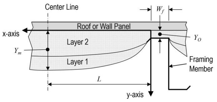
Figure A9.4.6.2-1 Geometry of double layers of fiberglass batts.
where X = distance from edge of purlin or girt, ft Y = distance from edge of roof panel or wall panel, ft L = length from edge of purlin or girt to centerline of cavity, ft wf = width of purlin or girt flange, ft Yo = distance between purlin or girt and the roof panel or wall panel, ft Ym = distance from edge of roof panel or wall panel at the cavity centerline, ft
Step 4: Determine the overall area-weighted U-factor for the entire system using Equation A9.4-9:
Ues
= L ------------------------------------------------------ Uco + wf 2 Ufo - L + wf 2
where
Ues = area-weighted U-factor for the entire system, Btu/h·ft [2] ·°F
wf = width of purlin or girt flange, ft
Step 5: Calculate the adjusted overall U-factor ( Uadj ) using Equation A9.4-10:
(A9.4-9)
(A9.4-10)
Uadj
1 = --------------------------------------------------0.8676 Ues + 1.1423
where
Uadj = adjusted overall U-factor represented by correlation with the finite element modeling, Btu/h·ft [2] ·°F
Step 6: If there is any continuous insulation present, calculate the overall U-factor using Equation A9.4-11:
1 U = ---------------------- - 1 -------- Uadj - + Rci
(A9.4-11)
A9.4.6.2 Double-Layer Roof. The U-factor of metal building roofs that are insulated with double layers of fiberglass insulation (see Figure A9.4.6.2-1) shall be calculated using the procedure outlined in this section. The procedure assumes the insulation is compressed over the purlin and there may be a thermal spacer block present.
There are six steps in the calculation process:
 - Step 1—Characterize the thermal conductivity of the fiberglass.

 - Step 2—Determine the _U-factor_ for the insulation in the cavity.

 - Step 3—Determine the _U-factor_ over the structural framing member.

 - Step 4—Area weight the _U-factors_ calculated in Steps 2 and 3.

 - Step 5—Determine the _U-factor_ from the finite element analysis results.

 - Step 6—Determine the _U-factor_ for any _continuous insulation_ if present.
Step 1: The thermal conductivity of the fiberglass batt insulation is represented by a thermal curve of the form in Equation A9.4-12:
268 ANSI/ASHRAE/IES Standard 90.1-2022 (I-P)