ASHRAE-90.1-2022- - Page 271
Extracted Content
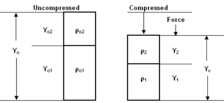
Figure A9.4.6.2-2 Compression of double layers of fiberglass insulation.
C k = A + B +
[—] [-]
where k = thermal conductivity, Btu/h·ft [2] ·°F = density, lb/ft [3]
(A9.4-12)
A = 0.014917 B = 0.0004377 C = 0.0056897 Step 2: Assume the double-layer fiberglass batt forms a parabolic profile defined by Equation A9.4-13:
X
Y = Yo + Ym - Yo [X] [---] L 2 - [---] L
(A9.4-13)
The presence of two layers of fiberglass adds complexity because each layer has distinct reference properties (see Table A9.4.6.1). As the double layers are compressed, the thickness of each layer needs to be determined by considering that each layer achieves the same compressive force. Instead of having a closedform analytical solution that predicts the U-factor for the cavity, the double-layer system requires that the parabolic profile be numerically integrated. The compression of the double-layer system is presented in Figure A9.4.6.2-2.
The thickness of the second layer ( Y 2) is described by Equation A9.4-14:
Y -----2 Yc
---------------------------------------------------- - - 1 o 21 - o 22 Yc 12
o 2 1
2 - o 2
1 2
Y -----2 - o 2 W 2 Yc o 21 - o 22
2 - o 2
1 2
(A9.4-14)
(A9.4-15a)
(A9.4-15b)
where Yc = compressed thickness of the double layers, ft o 1 = reference density of first layer, lb/ft [3]
o 2 = reference density of second layer, lb/ft [3]
W 1 = reference weight of first layer, lb/ft [2]
W 2 = reference weight of second layer, lb/ft [2]
The solutions to Equation A9.4-14 are Equations A9.4-15a and A9.4-15b:
where a = 1
ANSI/ASHRAE/IES Standard 90.1-2022 (I-P) 269