ASHRAE-90.1-2022- - Page 309
Extracted Content
Table G3.1 Modeling Requirements for Calculating Proposed Building Performance and Baseline Building Performance (Continued)
| Proposed Building Performance | Baseline Building Performance |
|---|---|
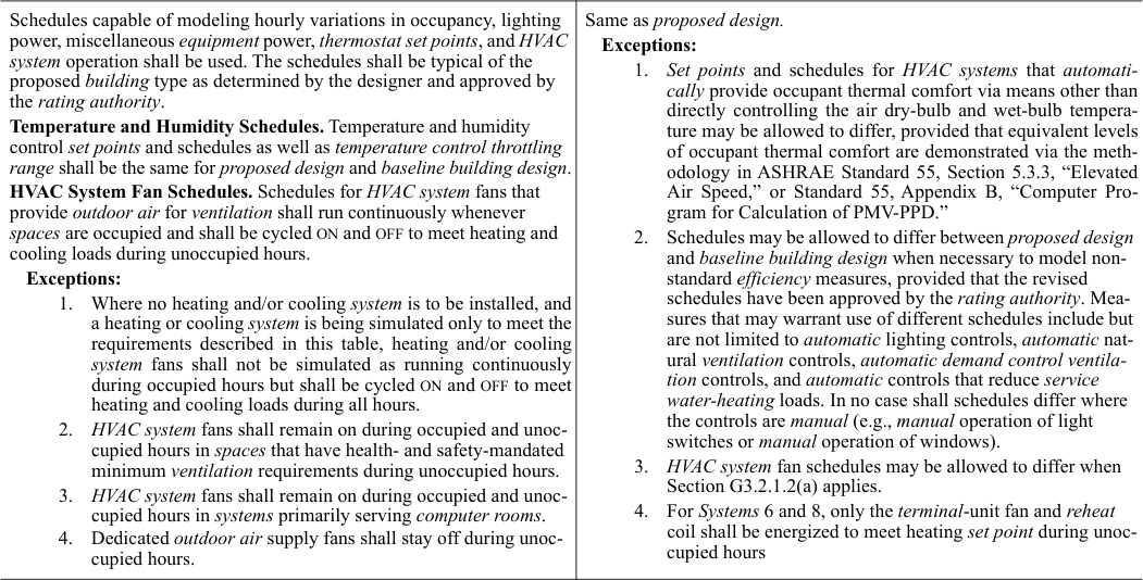
| 4. Schedule | |
Schedules capable of modeling hourly variations in occupancy, lighting
power, miscellaneous equipment power, thermostat set points, and HVAC
system operation shall be used. The schedules shall be typical of the
proposed building type as determined by the designer and approved by
the rating authority.
Temperature and Humidity Schedules. Temperature and humidity
control set points and schedules as well as temperature control throttling
range shall be the same for proposed design and baseline building design.
HVAC System Fan Schedules. Schedules for HVAC system fans that
provide outdoor air for ventilation shall run continuously whenever
spaces are occupied and shall be cycled ON and OFF to meet heating and
cooling loads during unoccupied hours.
Exceptions:
1. Where no heating and/or cooling system is to be installed, and
a heating or cooling system is being simulated only to meet the
requirements described in this table, heating and/or cooling
system fans shall not be simulated as running continuously
during occupied hours but shall be cycled ON and OFF to meet
heating and cooling loads during all hours.
2. HVAC system fans shall remain on during occupied and unoc-
cupied hours in spaces that have health- and safety-mandated
minimum ventilation requirements during unoccupied hours.
3. HVAC system fans shall remain on during occupied and unoc-
cupied hours in systems primarily serving computer rooms.
4. Dedicated outdoor air supply fans shall stay off during unoc-
cupied hours. | Same as proposed design.
Exceptions:
1. Set points and schedules for HVAC systems that automati-
cally provide occupant thermal comfort via means other than
directly controlling the air dry-bulb and wet-bulb tempera-
ture may be allowed to differ, provided that equivalent levels
of occupant thermal comfort are demonstrated via the meth-
odology in ASHRAE Standard 55, Section 5.3.3, “Elevated
Air Speed,” or Standard 55, Appendix B, “Computer Pro-
gram for Calculation of PMV-PPD.”
2. Schedules may be allowed to differ between proposed design
and baseline building design when necessary to model non-
standard efficiency measures, provided that the revised
schedules have been approved by the rating authority. Mea-
sures that may warrant use of different schedules include but
are not limited to automatic lighting controls, automatic nat-
ural ventilation controls, automatic demand control ventila-
tion controls, and automatic controls that reduce service
water-heating loads. In no case shall schedules differ where
the controls are manual (e.g., manual operation of light
switches or manual operation of windows).
3. HVAC system fan schedules may be allowed to differ when
Section G3.2.1.2(a) applies.
4. For Systems 6 and 8, only the terminal-unit fan and reheat
coil shall be energized to meet heating set point during unoc-
cupied hours |
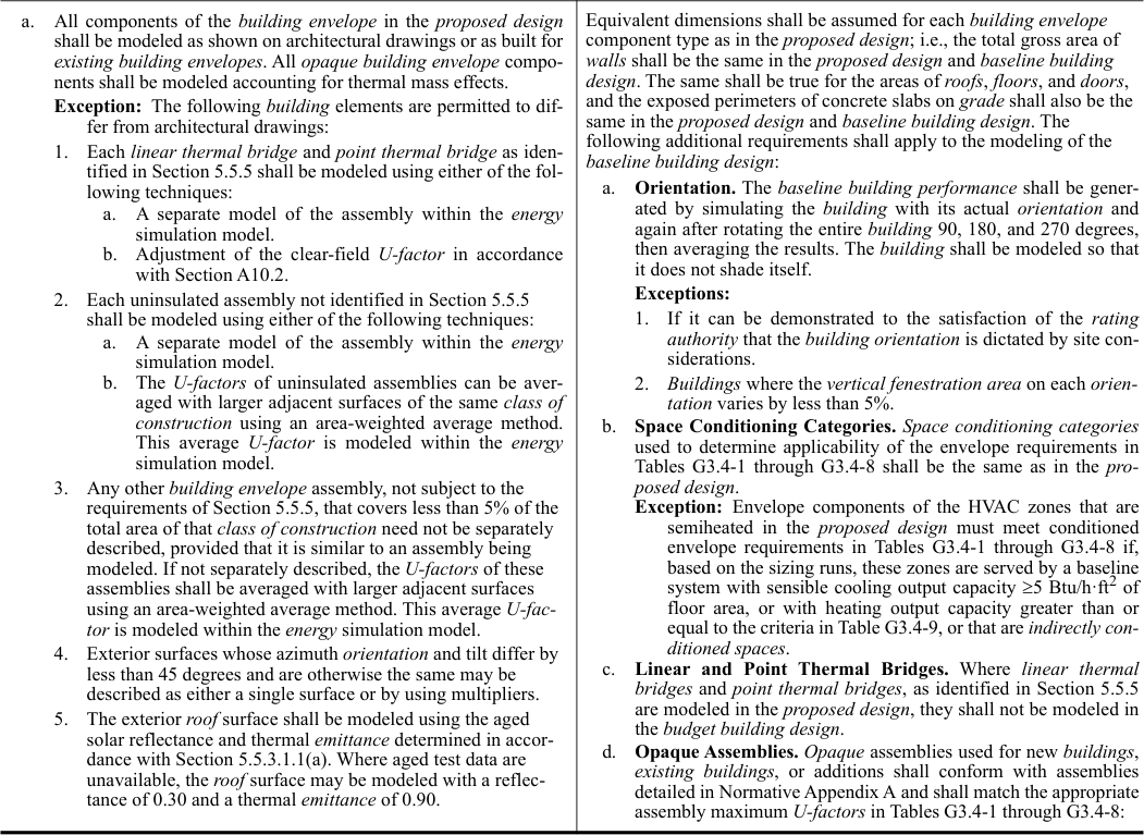
| 5. Building Envelope | |
a. All components of the building envelope in the proposed design
shall be modeled as shown on architectural drawings or as built for
existing building envelopes. All opaque building envelope compo-
nents shall be modeled accounting for thermal mass effects.
Exception: The following building elements are permitted to dif-
fer from architectural drawings:
1. Each linear thermal bridge and point thermal bridge as iden-
tified in Section 5.5.5 shall be modeled using either of the fol-
lowing techniques:
a. A separate model of the assembly within the energy
simulation model.
b. Adjustment of the clear-field U-factor in accordance
with Section A10.2.
2. Each uninsulated assembly not identified in Section 5.5.5
shall be modeled using either of the following techniques:
a. A separate model of the assembly within the energy
simulation model.
b. The U-factors of uninsulated assemblies can be aver-
aged with larger adjacent surfaces of the same class of
construction using an area-weighted average method.
This average U-factor is modeled within the energy
simulation model.
3. Any other building envelope assembly, not subject to the
requirements of Section 5.5.5, that covers less than 5% of the
total area of that class of construction need not be separately
described, provided that it is similar to an assembly being
modeled. If not separately described, the U-factors of these
assemblies shall be averaged with larger adjacent surfaces
using an area-weighted average method. This average U-fac-
tor is modeled within the energy simulation model.
4. Exterior surfaces whose azimuth orientation and tilt differ by
less than 45 degrees and are otherwise the same may be
described as either a single surface or by using multipliers.
5. The exterior roof surface shall be modeled using the aged
solar reflectance and thermal emittance determined in accor-
dance with Section 5.5.3.1.1(a). Where aged test data are
unavailable, the roof surface may be modeled with a reflec-
tance of 0.30 and a thermal emittance of 0.90. | Equivalent dimensions shall be assumed for each building envelope
component type as in the proposed design; i.e., the total gross area of
walls shall be the same in the proposed design and baseline building
design. The same shall be true for the areas of roofs, floors, and doors,
and the exposed perimeters of concrete slabs on grade shall also be the
same in the proposed design and baseline building design. The
following additional requirements shall apply to the modeling of the
baseline building design:
a. Orientation. The baseline building performance shall be gener-
ated by simulating the building with its actual orientation and
again after rotating the entire building 90, 180, and 270 degrees,
then averaging the results. The building shall be modeled so that
it does not shade itself.
Exceptions:
1. If it can be demonstrated to the satisfaction of the rating
authority that the building orientation is dictated by site con-
siderations.
2. Buildings where the vertical fenestration area on each orien-
tation varies by less than 5%.
b. Space Conditioning Categories. Space conditioning categories
used to determine applicability of the envelope requirements in
Tables G3.4-1 through G3.4-8 shall be the same as in the pro-
posed design.
Exception: Envelope components of the HVAC zones that are
semiheated in the proposed design must meet conditioned
envelope requirements in Tables G3.4-1 through G3.4-8 if,
based on the sizing runs, these zones are served by a baseline
system with sensible cooling output capacity ≥5 Btu/h·ft2 of
floor area, or with heating output capacity greater than or
equal to the criteria in Table G3.4-9, or that are indirectly con-
ditioned spaces.
c. Linear and Point Thermal Bridges. Where linear thermal
bridges and point thermal bridges, as identified in Section 5.5.5
are modeled in the proposed design, they shall not be modeled in
the budget building design.
d. Opaque Assemblies. Opaque assemblies used for new buildings,
existing buildings, or additions shall conform with assemblies
detailed in Normative Appendix A and shall match the appropriate
assembly maximum U-factors in Tables G3.4-1 through G3.4-8: |
ANSI/ASHRAE/IES Standard 90.1-2022 (I-P) 307