ASHRAE-90.1-2022- - Page 312
Extracted Content
Table G3.1 Modeling Requirements for Calculating Proposed Building Performance and Baseline Building Performance (Continued)
| Proposed Building Performance | Baseline Building Performance |
|---|---|
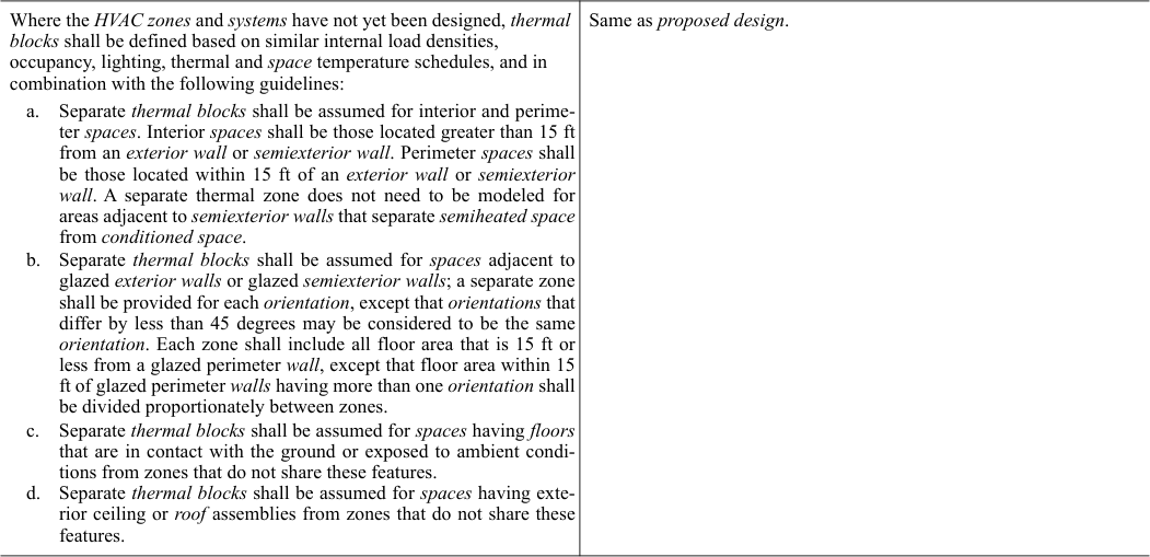
| 8. Thermal Blocks—HVAC Zones Not Designed | |
Where the HVAC zones and systems have not yet been designed, thermal
blocks shall be defined based on similar internal load densities,
occupancy, lighting, thermal and space temperature schedules, and in
combination with the following guidelines:
a. Separate thermal blocks shall be assumed for interior and perime-
ter spaces. Interior spaces shall be those located greater than 15 ft
from an exterior wall or semiexterior wall. Perimeter spaces shall
be those located within 15 ft of an exterior wall or semiexterior
wall. A separate thermal zone does not need to be modeled for
areas adjacent to semiexterior walls that separate semiheated space
from conditioned space.
b. Separate thermal blocks shall be assumed for spaces adjacent to
glazed exterior walls or glazed semiexterior walls; a separate zone
shall be provided for each orientation, except that orientations that
differ by less than 45 degrees may be considered to be the same
orientation. Each zone shall include all floor area that is 15 ft or
less from a glazed perimeter wall, except that floor area within 15
ft of glazed perimeter walls having more than one orientation shall
be divided proportionately between zones.
c. Separate thermal blocks shall be assumed for spaces having floors
that are in contact with the ground or exposed to ambient condi-
tions from zones that do not share these features.
d. Separate thermal blocks shall be assumed for spaces having exte-
rior ceiling or roof assemblies from zones that do not share these
features. | Same as proposed design. |
| 9. Thermal Blocks—Multifamily Residential Buildings | |
Residential spaces shall be modeled using at least one thermal block per
dwelling unit, except that those units facing the same orientations may be
combined into one thermal block. Corner units and units with roof or
floor loads shall only be combined with units sharing these features. | Same as proposed design. |
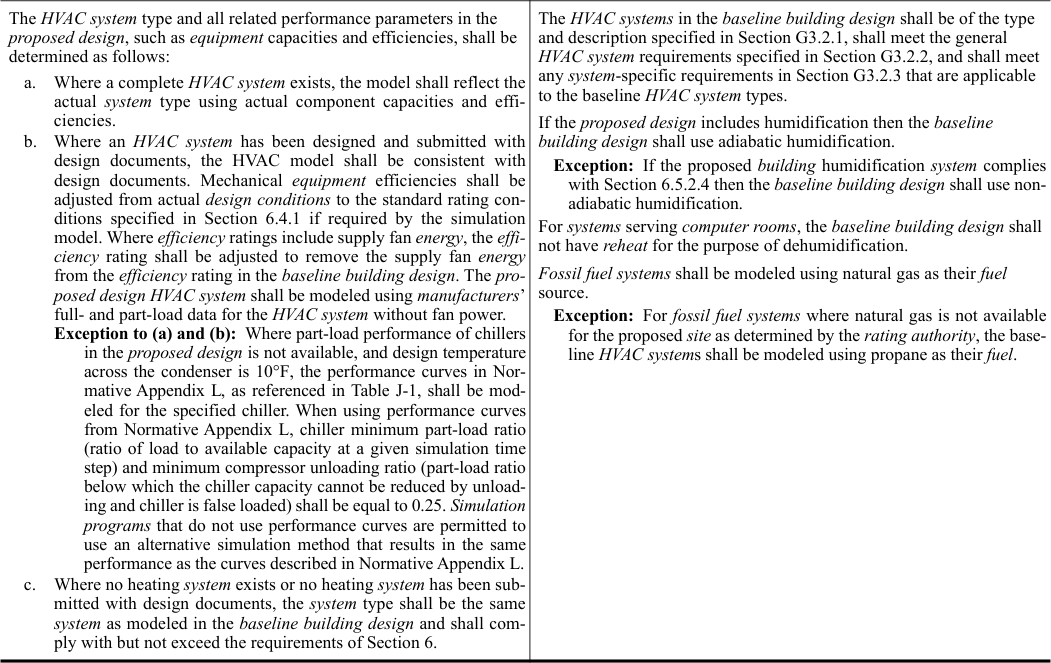
| 10. HVAC Systems | |
The HVAC system type and all related performance parameters in the
proposed design, such as equipment capacities and efficiencies, shall be
determined as follows:
a. Where a complete HVAC system exists, the model shall reflect the
actual system type using actual component capacities and effi-
ciencies.
b. Where an HVAC system has been designed and submitted with
design documents, the HVAC model shall be consistent with
design documents. Mechanical equipment efficiencies shall be
adjusted from actual design conditions to the standard rating con-
ditions specified in Section 6.4.1 if required by the simulation
model. Where efficiency ratings include supply fan energy, the effi-
ciency rating shall be adjusted to remove the supply fan energy
from the efficiency rating in the baseline building design. The pro-
posed design HVAC system shall be modeled using manufacturers’
full- and part-load data for the HVAC system without fan power.
Exception to (a) and (b): Where part-load performance of chillers
in the proposed design is not available, and design temperature
across the condenser is 10°F, the performance curves in Nor-
mative Appendix L, as referenced in Table J-1, shall be mod-
eled for the specified chiller. When using performance curves
from Normative Appendix L, chiller minimum part-load ratio
(ratio of load to available capacity at a given simulation time
step) and minimum compressor unloading ratio (part-load ratio
below which the chiller capacity cannot be reduced by unload-
ing and chiller is false loaded) shall be equal to 0.25. Simulation
programs that do not use performance curves are permitted to
use an alternative simulation method that results in the same
performance as the curves described in Normative Appendix L.
c. Where no heating system exists or no heating system has been sub-
mitted with design documents, the system type shall be the same
system as modeled in the baseline building design and shall com-
ply with but not exceed the requirements of Section 6. | The HVAC systems in the baseline building design shall be of the type
and description specified in Section G3.2.1, shall meet the general
HVAC system requirements specified in Section G3.2.2, and shall meet
any system-specific requirements in Section G3.2.3 that are applicable
to the baseline HVAC system types.
If the proposed design includes humidification then the baseline
building design shall use adiabatic humidification.
Exception: If the proposed building humidification system complies
with Section 6.5.2.4 then the baseline building design shall use non-
adiabatic humidification.
For systems serving computer rooms, the baseline building design shall
not have reheat for the purpose of dehumidification.
Fossil fuel systems shall be modeled using natural gas as their fuel
source.
Exception: For fossil fuel systems where natural gas is not available
for the proposed site as determined by the rating authority, the base-
line HVAC systems shall be modeled using propane as their fuel. |

310 ANSI/ASHRAE/IES Standard 90.1-2022 (I-P)