ASHRAE-Standard-55 - Full Extract
PDF Page 1

ANSI/ASHRAE Standard 55-2023
(Supersedes ANSI/ASHRAE Standard 55-2020) Includes ANSI/ASHRAE addenda listed in Appendix N
Thermal Environmental Conditions for Human Occupancy
See Appendix N for dates of approval by ASHRAE and the American National Standards Institute.
This Standard is under continuous maintenance by a Standing Standard Project Committee (SSPC) for which the Standards Committee has established a documented program for regular publication of addenda or revisions, including procedures for timely, documented, consensus action on requests for change to any part of the Standard. Instructions for how to submit a change can be found on the ASHRAE [®] website (www.ashrae.org/continuous-maintenance).
The latest edition of an ASHRAE Standard may be purchased from the ASHRAE website (www.ashrae.org) or from ASHRAE Customer Service, 180 Technology Parkway, Peachtree Corners, GA 30092. E-mail: orders@ashrae.org. Fax: 678-539-2129. Telephone: 404-636-8400 (worldwide), or toll free 1-800-527-4723 (for orders in US and Canada). For reprint permission, go to www.ashrae.org/permissions.
© 2023 ASHRAE ISSN 1041-2336
PDF includes hyperlinks for convenient navigation. Click on a reference to a section, table, figure, or equation to jump to its location. Return to the previous page via the bookmark menu.
Includes online access to the Compliance Documentation Template for Thermal Comfort (requires Microsoft [®] Excel [®] )


PDF Page 2
ASHRAE Standing Standard Project Committee 55 Cognizant TC: 2.1, Physiology and Human Environment
SPLS Liaison: David Robin ASHRAE Staff Liaison: Mark Weber
David Heinzerling, Chair and Webmaster Joyce Kim Julian Rimmer Josh Eddy, Secretary Baizhan Li David M. Rose Sama Aghniaey Shichao Liu Stefano Schiavon Peter F. Alspach Asit K. Mishra Lawrence J. Schoen Edward A. Arens Rodrigo Mora Peter Simmonds Robert Bean Gwelen Paliaga Aaron R. Smith Thomas B. Hartman Abhijeet Pande Amy L. Stadler Ongun B. Kazanci Zaccary A. Poots Federico Tartarini Essam E. Khalil Daniel J. Rice John G. Williams
ASHRAE STANDARDS COMMITTEE 2023–2024
Jonathan Humble, Chair Jay A. Kohler Gwelen Paliaga Douglas D. Fick, Vice-Chair Paul A. Lindahl, Jr. Karl L. Peterman Kelley P. Cramm James D. Lutz Justin M. Prosser Abdel K. Darwich Julie Majurin David Robin Drake H. Erbe Lawrence C. Markel Christopher J. Seeton Patricia Graef Margaret M. Mathison Paolo M. Tronville Jaap Hogeling Kenneth A. Monroe Douglas Tucker Jennifer A. Isenbeck Daniel H. Nall William F. Walter Phillip A. Johnson Philip J. Naughton Susanna S. Hanson, BOD ExO Gerald J. Kettler Kathleen Owen Ashish Rakheja, CO
Ryan Shanley, Senior Manager of Standards
SPECIAL NOTE This American National Standard (ANS) is a national voluntary consensus Standard developed under the auspices of ASHRAE. Consensus is defined by the American National Standards Institute (ANSI), of which ASHRAE is a member and which has approved this Standard as an ANS, as “substantial agreement reached by directly and materially affected interest categories. This signifies the concurrence of more than a simple majority, but not necessarily unanimity. Consensus requires that all views and objections be considered, and that an effort be made toward their resolution.” Compliance with this Standard is voluntary until and unless a legal jurisdiction makes compliance mandatory through legislation.
ASHRAE obtains consensus through participation of its national and international members, associated societies, and public review. ASHRAE Standards are prepared by a Project Committee appointed specifically for the purpose of writing the Standard. The Project Committee Chair and Vice-Chair must be members of ASHRAE; while other committee members may or may not be ASHRAE members, all must be technically qualified in the subject area of the Standard. Every effort is made to balance the concerned interests on all Project Committees.
The Senior Manager of Standards of ASHRAE should be contacted for
a. interpretation of the contents of this Standard, b. participation in the next review of the Standard, c. offering constructive criticism for improving the Standard, or d. permission to reprint portions of the Standard.
DISCLAIMER ASHRAE uses its best efforts to promulgate Standards and Guidelines for the benefit of the public in light of available information and accepted industry practices. However, ASHRAE does not guarantee, certify, or assure the safety or performance of any products, components, or systems tested, installed, or operated in accordance with ASHRAE’s Standards or Guidelines or that any tests conducted under its Standards or Guidelines will be nonhazardous or free from risk.
ASHRAE INDUSTRIAL ADVERTISING POLICY ON STANDARDS ASHRAE Standards and Guidelines are established to assist industry and the public by offering a uniform method of testing for rating purposes, by suggesting safe practices in designing and installing equipment, by providing proper definitions of this equipment, and by providing other information that may serve to guide the industry. The creation of ASHRAE Standards and Guidelines is determined by the need for them, and conformance to them is completely voluntary.
In referring to this Standard or Guideline and in marking of equipment and in advertising, no claim shall be made, either stated or implied, that the product has been approved by ASHRAE.
PDF Page 3
CONTENTS ANSI/ASHRAE Standard 55-2023 Thermal Environmental Conditions for Human Occupancy
SECTION PAGE
Foreword… 2
1 Purpose … 2
2 Scope … 2
3 Definitions… 2
4 General Requirements … 5
5 Conditions That Provide Thermal Comfort … 5
6 Design Compliance … 19
7 Evaluation of Comfort in Existing Buildings… 21
8 References … 24
Normative Appendix A: Operative Temperature and Procedure for Section 5.3… 25
Normative Appendix B: Computer Program for Calculation of Predicted Mean Vote (PMV)… 26
Normative Appendix C: Procedure for Calculating Comfort Impact of Solar Gain on Occupants … 28
Normative Appendix D: Procedure for Evaluating Cooling Effect of Elevated Air Speed Using
Standard Effective Temperature (SET)… 36
Informative Appendix E: Conditions That Provide Thermal Comfort … 42
Informative Appendix F: Use of Metabolic Rate Data… 45
Informative Appendix G: Clothing Insulation… 46
Informative Appendix H: Comfort Zones Defining Satisfactory Thermal Conditions in Occupied Space … 48
Informative Appendix I: Local Discomfort and Variations with Time… 50
Informative Appendix J: Occupant-Controlled Naturally Conditioned Spaces… 55
Informative Appendix K: Compliance Documentation Template for Thermal Comfort … 58
Informative Appendix L: Measurements, Surveys, and Evaluation of Comfort in Existing Spaces:
Parts 1 and 2… 59
Informative Appendix M: Informative References and Bibliography… 68
Informative Appendix N: Addenda Description… 72
Online Supporting Files: www.ashrae.org/55Files
NOTE
Approved addenda, errata, or interpretations for this standard can be downloaded free of charge from the ASHRAE website at www.ashrae.org/technology.
© 2023 ASHRAE 180 Technology Parkway · Peachtree Corners, GA 30092 · www.ashrae.org · All rights reserved. ASHRAE is a registered trademark of the American Society of Heating, Refrigerating and Air-Conditioning Engineers, Inc.
ANSI is a registered trademark of the American National Standards Institute.
PDF Page 4
(This foreword is not part of this standard. It is merely informative and does not contain requirements necessary for conformance to the standard. It has not been processed according to the ANSI require- ments for a standard and may contain material that has not been subject to public review or a consen- sus process. Unresolved objectors on informative material are not offered the right to appeal at ASHRAE or ANSI.)
FOREWORD
This 2023 edition of ASHRAE Standard 55 incorporates eleven addenda to the 2020 edition that were writ- ten with a renewed focus on organizational clarity.
The core of the standard in Sections 4 and 5 specifies methods to determine thermal environmental con- ditions (temperature, humidity, air speed, and radiant effects) in buildings and other spaces that a signifi- cant proportion of the occupants will find acceptable at a certain metabolic rate and clothing level. The comprehensive analytical method to determine these conditions uses calculation algorithms included in the standard and appendices, all of which are implemented in the Thermal Comfort Tool.
Section 6 contains requirements for demonstrating that a design of an occupied space or building meets the comfort requirements in Sections 4 and 5. Section 7 includes requirements for the measurement and eval- uation of existing thermal environments and is also applicable to commissioning.
Because the two personal characteristics of occupants (metabolic rate and clothing level) vary, operat- ing set points for buildings are not mandated by this standard.
Standard 55 was first published in 1966 and republished in 1974, 1981, and 1992. As of 2004, it is updated using ASHRAE’s continuous maintenance procedures. According to these procedures, the standard is continuously revised by addenda that are publicly reviewed, approved by ASHRAE and ANSI, and pub- lished and posted for free on the ASHRAE website.
The eleven approved addenda to the 2020 edition are summarized in detail in Informative Appendix N. The most noteworthy changes include
• A new method for the assessment of local thermal discomfort with vertical air temperature gradient between the head level and ankle level
• A wider applicability of the standard, which now covers metabolic rates up to 4 from 2
• A consolidation and simplification of calculation methods in the standard, which are now limited to two methods—standard and adaptive—and a new flow chart that provides guidance on when to use each cal- culation method
• Updates to informative references
• An overhaul of the documentation requirements of the standard (Section 6) that includes additions, clari- fications, and simplifications, along with a new example spreadsheet compliance form that replaces the prior example form
1. PURPOSE
The purpose of this standard is to specify the combinations of indoor thermal environmental factors and personal factors that will produce satisfactory thermal environmental conditions for a majority of the occupants within the space.
2. SCOPE
2.1 The environmental factors addressed in this standard are temperature, thermal radiation, humidity, and air speed; the personal factors are those of activity and clothing. 2.2 It is intended that all of the criteria in this standard be applied together, as comfort in the indoor environment is complex and responds to the interaction of all of the factors that are addressed herein. 2.3 This standard specifies thermal environmental conditions acceptable for healthy adults at atmospheric pressure equivalent to altitudes up to 3000 m (10,000 ft) in indoor spaces designed for human occupancy for periods not less than 15 minutes. 2.4 This standard does not address such nonthermal environmental factors as air quality, acoustics, illumination, or other physical, chemical, or biological space contaminants that may affect comfort or health. 2.5 This standard shall not be used to override any safety, health, or critical process requirements.
3. DEFINITIONS
adaptive model: a model that relates indoor design temperatures or acceptable temperature ranges to outdoor meteorological or climatological parameters. ( Informative Note: Adaptive model is another name for the
2 ANSI/ASHRAE Standard 55-2023
PDF Page 5
method described in Section 5.4, “Determining Acceptable Thermal Conditions in Occupant-Controlled Naturally Conditioned Spaces (Adaptive Model).”
air speed: the rate of air movement at a point, without regard to direction.
air speed, average (Va): the average air speed surrounding a representative occupant. The average is with respect to location and time. The spatial average is for three heights as defined for average air temperature ta . For an occupant moving in a space, the sensors shall follow the movements of the occupant. The air speed is averaged over an interval not less than one and not greater than three minutes. Variations that occur over a period greater than three minutes shall be treated as multiple different air speeds.
climate data: hourly, site-specific values of representative meteorological data, such as temperature, wind, speed, solar radiation, and relative humidity. For cities or urban regions with several climate data entries, and for locations where climate data are not available, the designer shall select available weather or meteorological data that best represents the climate at the building site. (See ASHRAE Handbook—Fundamentals [ 1], Chapter 14 for data sources.)
clo: a unit used to express the thermal insulation provided by garments and clothing ensembles; 1 clo = 0.155 m [2] ·°C/W (0.88 ft [2] ·h·°F/Btu).
comfort zone: a zone whose boundaries enclose sets of environmental and personal conditions that provide thermal satisfaction according to the standard.
corrective power: the ability of a personal comfort system (PCS), expressed in degrees (°C [°F]), to correct thermal conditions toward the comfort zone, measured as the difference between two operative temperatures at which equal thermal sensation is achieved—one a temperature in the comfort zone with no PCS, and one with PCS in use, with all other environmental factors held constant. (See personal comfort system .)
direct-beam solar radiation: solar radiation from the direction of the sun, expressed in W/m [2] (Btuh/ft [2] ). Does not include reflected or diffuse solar radiation. Also known as “direct normal insolation” ( Idir ).
draft: the unwanted local cooling of the body caused by air movement.
environment, satisfactory thermal: a thermal environment that a substantial majority (more than 80%) of the occupants find thermally satisfactory.
environment, thermal: the thermal environmental conditions that affect a person’s heat loss.
exceedance hours: the number of occupied hours within a defined time period in which the environmental conditions in an occupied space are outside of the comfort zone.
garment: a single piece of clothing.
generally accepted engineering standard: see ASHRAE/IES Standard 90.1 [ 2] .
humidity: a general reference to the moisture content of the air. It is expressed in terms of several thermodynamic variables, including vapor pressure, dew-point temperature, wet-bulb temperature, humidity ratio, and relative humidity. It is spatially and temporally averaged in the same manner as air temperature. ( Informa- tive Note: Any one of these humidity variables must be used in conjunction with dry-bulb temperature in order to describe a specific air condition.)
insulation, clothing (Icl ): the resistance to sensible heat transfer provided by a clothing ensemble, expressed in units of clo. ( Informative Note: The definition of clothing insulation relates to heat transfer from the whole body and, thus, also includes the uncovered parts of the body, such as head and hands.)
insulation, garment (Iclu ): the increased resistance to sensible heat transfer obtained from adding an individual garment over the nude body, expressed in units of clo.
local thermal discomfort: the thermal discomfort caused by locally specific conditions such as a vertical air temperature gradient between the feet and the head, by radiant temperature asymmetry, by local convective cooling (draft), or by contact with a hot or cold floor.
metabolic rate (met): the rate of transformation of chemical energy into heat and mechanical work by metabolic activities of an individual, per unit of skin surface area (expressed in units of met) equal to 58.2 W/m [2]
(18.4 Btu/h·ft [2] ), which is the energy produced per unit skin surface area of an average person seated at rest.
occupant, representative: an individual or composite or average of several individuals that is representative of the population occupying a space for 15 minutes or more.
occupant-controlled naturally conditioned spaces: those spaces where the thermal conditions of the space are regulated primarily by occupant-controlled openings in the envelope.
ANSI/ASHRAE Standard 55-2023 3
PDF Page 6
occupant-controlled openings: openings such as windows or vents that are directly controlled by the occupants of a space. Such openings may be manually controlled or controlled through the use of electrical or mechanical actuators under direct occupant control. occupied zone: the region normally occupied by people within a space. In the absence of known occupant locations, the occupied zone is to be between the floor and 1.8 m (6 ft) above the floor and more than 1.0 m (3.3 ft) from outside walls/windows or fixed heating, ventilating, or air-conditioning equipment, and 0.3 m (1 ft) from internal walls. personal comfort system (PCS): a device, under the control of the occupant, to heat and/or cool individual occupants directly, or heat and/or cool the immediate thermal environment of an individual occupant, without affecting the thermal environment of other occupants. personal environment: the thermal environment immediately surrounding an occupant. predicted mean vote (PMV): an index that predicts the mean value of the thermal sensation votes (selfreported perceptions) of a large group of persons on a sensation scale expressed from –3 to +3 corresponding to the categories “cold,” “cool,” “slightly cool,” “neutral,” “slightly warm,” “warm,” and “hot.” predicted percentage of dissatisfied (PPD): an index that establishes a quantitative prediction of the percentage of thermally dissatisfied people determined from PMV. radiant temperature asymmetry: the difference between the plane radiant temperature tpr in opposite directions. The vertical radiant temperature asymmetry is with plane radiant temperatures in the upward and downward directions. The horizontal radiant temperature asymmetry is the maximum radiant temperature asymmetry for all horizontal directions. The radiant temperature asymmetry is determined at waist level, 0.6 m (24 in.) for a seated occupant and 1.1 m (43 in.) for a standing occupant. (See ASHRAE Handbook—Fundamentals [ 1], Chapter 9 for a more complete description of plane radiant temperature and radiant asymmetry.) readily accessible: capable of being reached quickly for operation without requiring those for whom ready access is required to climb over or remove obstacles or to resort to portable ladders, chairs, or other climbing aids. sensation, thermal: a conscious subjective expression of an occupant’s thermal perception of the environment, commonly expressed using the categories “cold,” “cool,” “slightly cool,” “neutral,” “slightly warm,” “warm,” and “hot.” shade openness factor: percentage of the area of a shade or blind material that is unobstructed. For woven shades, shade openness factor is the weave openness. solar transmittance, total (Tsol): total solar radiation transmittance through a fenestration unit, including glazing unit and internal blinds or shades. See Normative Appendix C for acceptable calculation methods. temperature, air: the temperature of the air at a point. temperature, air average (ta): the average air temperature surrounding a representative occupant. The average is with respect to location and time. The spatial average is the numerical average of the air temperature at the ankle level, the waist level, and the head level. These levels are 0.1, 0.6, and 1.1 m (4, 24, and 43 in.) for seated occupants; 0.1, 1.1, and 1.7 m (4, 43, and 67 in.) for standing occupants, and the mean height of the body for horizontal occupants. Time averaging is over a period not less than three and not more than 15 minutes. temperature, dew-point (tdp ): the air temperature at which the water vapor in air at a given barometric pressure will condense into a liquid. temperature, floor (tf): the surface temperature of the floor where it is in contact with the representative occupants’ feet. temperature, long-wave mean radiant (trlw ): radiant temperature from long-wave radiation from interior surfaces expressed as a spatial average of the temperature of surfaces surrounding the occupant, weighted by their view factors with respect to the occupant. (See ASHRAE Handbook—Fundamentals [ 1], Chapter 9.) temperature, mean daily outdoor air (tmda out ): any arithmetic mean for a 24-hour period permitted in Section 5.4 of the standard. Mean daily outdoor air temperature is used to calculate prevailing mean outdoor air temperature tpma out . temperature, mean radiant (tr ): the temperature of a uniform, black enclosure that exchanges the same amount of heat by radiation with the occupant as the actual surroundings. It is a single value for the entire body and accounts for both long-wave mean radiant temperature trlw and short-wave mean radiant temperature trsw . temperature, operative (to ): the uniform temperature of an imaginary black enclosure, and the air within it, in which an occupant would exchange the same amount of heat by radiation plus convection as in the actual non
trlw
tmda out
tpma out
tr
and accounts for both long-wave mean radiant temperature trlw
trsw .
4 ANSI/ASHRAE Standard 55-2023
PDF Page 7
uniform environment; calculated in accordance with Normative Appendix A of this standard. (See ASHRAE Handbook—Fundamentals [ 1], Chapter 9, for further discussion of operative temperature.) temperature, plane radiant (tpr ): the uniform temperature of an enclosure in which the incident radiant flux on one side of a small plane element is the same as in the existing environment. temperature, prevailing mean outdoor air ( tpma out ): when used as an input variable in Figure 5-9 for the adaptive model, this temperature is based on the arithmetic average of the mean daily outdoor temperatures over some period of days as permitted in Section 5.4.2.1. temperature, short-wave mean radiant (trsw ): radiant temperature from short-wave direct and diffuse solar radiation expressed as an adjustment to long-wave mean radiant temperature trlw using the calculation procedure in Normative Appendix C of this standard. temperature, standard effective (SET): the temperature of a hypothetical isothermal environment at 50% rh, <0.1 m/s (20 fpm) average air speed Va, and tr = ta, in which the total heat loss from the skin of an imaginary occupant wearing clothing, standardized for the activity concerned, is the same as that from a person in the actual environment with actual clothing and activity level. thermal comfort: that condition of mind that expresses satisfaction with the thermal environment and is assessed by subjective evaluation. thermal zone: an area of a building designated by the designer such that the comfort zone is maintained within the occupied zone by local controls for its representative occupant(s).
4. GENERAL REQUIREMENTS
4.1 Where information is required to be identified in this standard, it shall be documented in accordance with and in addition to the requirements in Section 6. 4.2 Identify all of the space types to which the standard is being applied and any locations within a space to which it is not applied. 4.3 For each space type, at least one representative occupant shall be identified. If any known set of occupants is excluded from consideration then these excluded occupants shall be identified. Informative Note: For example, the customers in a restaurant may have a metabolic rate near 1.0 met, while
the servers may have a metabolic rate closer to 2.0 met. Per Section 5.2.1.1, each of these groups of occupants shall be considered separately in determining the conditions required for comfort. In some situations such as this, it will not be possible to provide an acceptable level or the same level of comfort to all disparate groups of occupants. 4.4 For each representative occupant, the metabolic rate M in mets and the insulation Icl in clo shall be determined. 4.5 The thermal environment required for comfort is determined in accordance with Section 5 of this standard.
5. CONDITIONS THAT PROVIDE THERMAL COMFORT
5.1 General Requirements. Section 5 of this standard shall be used to determine the acceptable thermal environment for each representative occupant of a space. Section 5.2 is used to determine representative occupant characteristics.
tpma out
trsw
trlw
tr = ta
Section 5.3 in its entirety or Section 5.4 in its entirety shall be identified as the approach used in determining the acceptable thermal environment. Section 5.3 shall be permitted to be used in any space, and Section 5.4 shall be permitted to be used only in those spaces that meet the applicability criteria in Section 5.4.1. Determine operative temperature to in accordance with Normative Appendix A.
This section covers the determination of the following six factors in steady state. All six factors shall be addressed when defining conditions for acceptable thermal comfort:
a. Metabolic rate b. Clothing insulation c. Air temperature d. Radiant temperature e. Air speed f. Humidity
Informative Notes:
- It is possible for all six of these factors to vary with time. The first two are characteristics of the occupant, and the remaining four are conditions of the thermal environment.
- Average air speed and average air temperature have precise definitions in this standard. See Section 3 for all defined terms.
ANSI/ASHRAE Standard 55-2023 5
PDF Page 8
5.2 Method for Determining Occupant Characteristics 5.2.1 Metabolic Rate 5.2.1.1 Rate for Each Representative Occupant. For each representative occupant, determine the metabolic rate associated with the occupant’s activities. Averaged metabolic rates shall not be used to represent multiple occupants whose metabolic rates differ by more than 0.1 met. Informative Note: For example, in an office setting, when comparing an occupant who is seated and read ing at 1.0 met with an occupant that is typing at 1.1 met, they can be grouped as a single representative occupant. If the same seated occupant is compared to an occupant who is seated and filing at 1.2 met, each shall be considered separately when determining the conditions required for thermal comfort. 5.2.1.2 Rate Determination. Use one or a combination of the following methods to determine metabolic rate:
a. Metabolic rates for typical occupant activity types given in Table 5-1 shall be used to describe the repre sentative occupant. Where a range is given, select a single value within that range based on characteristics of the activity. If a proposed occupant activity type is not listed in Table 5-1, the most similar activity type based on characteristics of the activity shall be used. b. Interpolate between or extrapolate from the values given in Table 5-1. c. Use estimation and/or measurement methods described in ASHRAE Handbook—Fundamentals [ 1], Chap ter 9. d. Use other approved engineering or physiological methods.
5.2.1.3 Time-Weighted Averaging. Use a time-weighted average metabolic rate for individuals with activities that vary. Such averaging shall not be applied where an activity persists for more than one hour. In that case, two distinct metabolic rates shall be used. Informative Note: For example, a person who spends 30 minutes out of each hour “lifting/packing,” 15
minutes “filing, standing,” and 15 minutes “walking about” has an average metabolic rate of 0.50 × 2.1 + 0.25 × 1.4 + 0.25 × 1.7 = 1.8 met. However, a person who is engaged in “lifting/packing” for more than one hour and then “filing, standing” for more than one hour shall be treated as having two distinct metabolic rates per Section 5.2.1.1. 5.2.1.4 High Metabolic Rates. This standard does not apply to occupants whose time-averaged metabolic rate exceeds 4.0 met.
5.2.2 Clothing Insulation 5.2.2.1 Insulation for Each Representative Occupant 5.2.2.1.1 For each representative occupant, determine the clothing insulation Icl in clo. 5.2.2.1.2 Averaged clothing insulation Icl shall not be used to represent multiple occupants whose clothing insulation differs by more than 0.15 clo. Exception to 5.2.2.1.2: Where individuals are free to adjust clothing to account for individual differences
in response to the thermal environment, it is permitted to use a single representative occupant with an average clothing insulation Icl value to represent multiple individuals. 5.2.2.2 Insulation Determination. Use one or a combination of the following methods to determine clothing insulation Icl :
a. Use the data presented in Table 5-2 for the expected ensemble of each representative occupant. b. Add or subtract the insulation of individual garments in Table 5-3 from the ensembles in Table 5-2 to
determine the insulation of ensembles not listed. c. Determine a complete clothing ensemble using the sum of the individual values listed for each item of
clothing in the ensemble in Table 5-3. d. It is permitted, but not required, to adjust any of the previous methods for seated occupants using Table
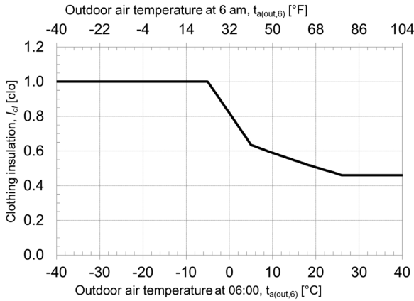
5-4. e. Interpolate between or extrapolate from the values given in Tables 5-3 and 5-4. f. Use Figure 5-1 to determine the clothing insulation Icl of a representative occupant for a day as a function of outdoor air temperature at 06:00 a.m., ta(out,6) .
Clothing insulation Icl determined in accordance with Figure 5-1 is permitted but not required to be adjusted to account for unique dress code or cultural norms using other methods in Section 5.2.2.2 or approved engineering methods. g. Use measurement with thermal manikins or other approved engineering methods.
6 ANSI/ASHRAE Standard 55-2023
PDF Page 9
Table 5-1 Metabolic Rates for Typical Tasks
Activity
Resting
Metabolic Rate
met W/m [2] Btu/h·ft [2]
Sleeping 0.7 40 13
Reclining 0.8 45 15
Seated, quiet 1.0 60 18
Standing, relaxed 1.2 70 22
Walking (on level surface)
0.9 m/s, 3.2 km/h, 2.0 mph 2.0 115 37
1.2 m/s, 4.3 km/h, 2.7 mph 2.6 150 48
1.8 m/s, 6.8 km/h, 4.2 mph 3.8 220 70
Office Activities
Reading, seated 1.0 55 18
Writing 1.0 60 18
Typing 1.1 65 20
Filing, seated 1.2 70 22
Filing, standing 1.4 80 26
Walking about 1.7 100 31
Lifting/packing 2.1 120 39
Driving/Flying
Automobile 1.0 to 2.0 60 to 115 18 to 37
Aircraft, routine 1.2 70 22
Aircraft, instrument landing 1.8 105 33
Aircraft, combat 2.4 140 44
Heavy vehicle 3.2 185 59
Miscellaneous Occupational Activities
Cooking 1.6 to 2.0 95 to 115 29 to 37
House cleaning 2.0 to 3.4 115 to 200 37 to 63
Seated, heavy limb movement 2.2 130 41
Machine work
Sawing (table saw) 1.8 105 33
Light (electrical industry) 2.0 to 2.4 115 to 140 37 to 44
Heavy 4.0 235 74
Handling 50 kg (100 lb) bags 4.0 235 74
Pick and shovel work 4.0 to 4.8 235 to 280 74 to 88
Miscellaneous Leisure Activities
Dancing, social 2.4 to 4.4 140 to 255 44 to 81
Calisthenics/exercise 3.0 to 4.0 175 to 235 55 to 74
Tennis, single 3.6 to 4.0 210 to 270 66 to 74
Basketball 5.0 to 7.6 290 to 440 90 to 140
Wrestling, competitive 7.0 to 8.7 410 to 505 130 to 160
ANSI/ASHRAE Standard 55-2023 7
PDF Page 10
Table 5-2 Clothing Insulation Icl Values for Typical Ensembles
Clothing Description Garments Included [ a] Icl , clo
Trousers (1) Trousers, short-sleeve shirt 0.57
(2) Trousers, long-sleeve shirt 0.61
(3) #2 plus suit jacket 0.96
(4) #2 plus suit jacket, vest, t-shirt 1.14
(5) #2 plus long-sleeve sweater, t-shirt 1.01
(6) #5 plus suit jacket, long underwear bottoms 1.30
Skirts/dresses (7) Knee-length skirt, short-sleeve shirt (sandals) 0.54
(8) Knee-length skirt, long-sleeve shirt, full slip 0.67
(9) Knee-length skirt, long-sleeve shirt, half slip, long-sleeve sweater 1.10
(10) Knee-length skirt, long-sleeve shirt, half slip, suit jacket 1.04
(11) Ankle-length skirt, long-sleeve shirt, suit jacket 1.10
Shorts (12) Walking shorts, short-sleeve shirt 0.36
Overalls/coveralls (13) Long-sleeve coveralls, t-shirt 0.72
(14) Overalls, long-sleeve shirt, t-shirt 0.89
(15) Insulated coveralls, long-sleeve thermal underwear tops and bottoms 1.37
Athletic (16) Sweat pants, long-sleeve sweatshirt 0.74
Sleepwear (17) Long-sleeve pajama tops, long pajama trousers, short 3/4 length robe (slippers, no socks) 0.96
a. All clothing ensembles, except where otherwise indicated in parentheses, include shoes, socks, and briefs or panties. All skirt/dress clothing ensembles include pantyhose and no
additional socks.
5.2.2.3 Limits of Applicability. This standard does not apply to occupants
a. Whose clothing insulation exceeds 1.5 clo b. Whose clothing is highly impermeable to moisture transport (e.g., chemical protective clothing or rain
gear) c. Who are sleeping, reclining in contact with bedding, or able to adjust blankets or bedding 5.3 Determining Satisfactory Thermal Environment in Occupied Spaces 5.3.1 Applicability. Section 5.3 is permitted to be used to determine the requirements for thermal comfort in all occupied spaces within the scope of this standard. See Sections 5.2.1.4 and 5.2.2.3 for limits to the occupants’ clothing and activity levels.
5.3.2 Methodology. The predicted mean vote (PMV) model with adjustments for solar radiation and elevated air speed is used to determine the boundaries of the comfort zone. Compliance with Section 5.3 is achieved if –0.5 < PMV < +0.5 and the requirements of Sections 5.3.5 and 5.3.6 are met. See Section 6 for full design compliance requirements.
A computer code implementation of the PMV model is provided in Normative Appendix B. The adjustment for solar radiation is described per Section 5.3.3 and Normative Appendix C. The adjustment for elevated air speed is described inSection 5.3.4 and Normative Appendix D.
Normative Appendix A through Normative Appendix D provide the full methodology to comply with this section, including computer code implementations. The Thermal Comfort Tool [ 3] includes these methods and is permitted to be used to comply with this section. Alternative calculation methods are permitted but it is the user’s responsibility to verify and document that the method used yields the same results.
Figures 5-2 and 5-3 provide graphical examples of comfort zones using the PMV model in still-air conditions. Direct use of these charts to comply with this section is allowable for the specific input conditions described on each chart. In each figure, the darker-shade comfort zone is the same, and the lighter-shade comfort zone represents a single altered input: clothing insulation (Figure 5-2) and metabolic rate (Figure 5-3).
5.3.3 Solar Radiation Adjustment. When direct-beam solar radiation falls on a representative occupant,
the mean radiant temperature tr shall account for long-wave mean radiant temperature trlw and short-wave
mean radiant temperature t rsw using one of the following options:
8 ANSI/ASHRAE Standard 55-2023
PDF Page 11
| Table 5-3 Garment Insulation Iclu | Col2 |
|---|---|
| Garment Description a Iclu, clo | Garment Description a Iclu, clo |
| Underwear Bra 0.01 Panties 0.03 Men’s briefs 0.04 T-shirt 0.08 Half slip 0.14 Long underwear bottoms 0.15 Full slip 0.16 Long underwear top 0.20 | Dress and Skirts b Skirt (thin) mm 0.14 Skirt (thick) 0.23 Sleeveless, scoop neck (thin) 0.23 Sleeveless, scoop neck (thick), i.e., jumper 0.27 Short-sleeve shirtdress (thin) 0.29 Long-sleeve shirtdress (thin) 0.33 Long-sleeve shirtdress (thick) 0.47 |
| Underwear Bra 0.01 Panties 0.03 Men’s briefs 0.04 T-shirt 0.08 Half slip 0.14 Long underwear bottoms 0.15 Full slip 0.16 Long underwear top 0.20 | Sweaters Sleeveless vest (thin) 0.13 Sleeveless vest (thick) 0.22 Long-sleeve (thin) 0.25 Long-sleeve (thick) 0.36 |
| Footwear Ankle-length athletic socks 0.02 Panty hose/stockings 0.02 Sandals/thongs 0.02 Shoes 0.02 Slippers (quilted, pile lined) 0.03 Calf-length socks 0.03 Knee socks (thick) 0.06 Boots 0.10 Shirts and Blouses Sleeveless/scoop-neck blouse 0.12 Short-sleeve knit sport shirt 0.17 Short-sleeve dress shirt 0.19 Long-sleeve dress shirt 0.25 Long-sleeve flannel shirt 0.34 Long-sleeve sweatshirt 0.34 | Footwear Ankle-length athletic socks 0.02 Panty hose/stockings 0.02 Sandals/thongs 0.02 Shoes 0.02 Slippers (quilted, pile lined) 0.03 Calf-length socks 0.03 Knee socks (thick) 0.06 Boots 0.10 Shirts and Blouses Sleeveless/scoop-neck blouse 0.12 Short-sleeve knit sport shirt 0.17 Short-sleeve dress shirt 0.19 Long-sleeve dress shirt 0.25 Long-sleeve flannel shirt 0.34 Long-sleeve sweatshirt 0.34 |
| Footwear Ankle-length athletic socks 0.02 Panty hose/stockings 0.02 Sandals/thongs 0.02 Shoes 0.02 Slippers (quilted, pile lined) 0.03 Calf-length socks 0.03 Knee socks (thick) 0.06 Boots 0.10 Shirts and Blouses Sleeveless/scoop-neck blouse 0.12 Short-sleeve knit sport shirt 0.17 Short-sleeve dress shirt 0.19 Long-sleeve dress shirt 0.25 Long-sleeve flannel shirt 0.34 Long-sleeve sweatshirt 0.34 | Suit Jackets and Vests c Sleeveless vest (thin) 0.10 Sleeveless vest (thick) 0.17 Single-breasted (thin) 0.36 Single-breasted (thick) 0.44 Double-breasted (thin) 0.42 Double-breasted (thick) 0.48 Sleepwear and Robes Sleeveless short gown (thin) 0.18 Sleeveless long gown (thin) 0.20 Short-sleeve hospital gown 0.31 Short-sleeve short robe (thin) 0.34 Short-sleeve pajamas (thin) 0.42 Long-sleeve long gown (thick) 0.46 Long-sleeve short wrap robe (thick) 0.48 Long-sleeve pajamas (thick) 0.57 Long-sleeve long wrap robe (thick) 0.69 |
| Trousers and Coveralls Short shorts 0.06 Walking shorts 0.08 Straight trousers (thin) 0.15 Straight trousers (thick) 0.24 Sweatpants 0.28 Overalls 0.30 Coveralls 0.49 | Trousers and Coveralls Short shorts 0.06 Walking shorts 0.08 Straight trousers (thin) 0.15 Straight trousers (thick) 0.24 Sweatpants 0.28 Overalls 0.30 Coveralls 0.49 |
a. “Thin” refers to garments made of lightweight, thin fabrics often worn in the summer; “thick” refers to garments made of heavyweight, thick fabrics often worn in the winter. b. Knee-length dresses and skirts c. Lined vests
a. Full calculation of mean radiant temperature tr as follows:
- Step 1: Determine long-wave mean radiant temperature trlw .
- Step 2: Determine short-wave mean radiant temperature trsw using Normative Appendix C.
- Step 3: Mean radiant temperature tr is equal to trlw +
trsw as determined in Steps 1 and 2. b. Use a mean radiant temperature tr that is 2.8°C (5°F) higher than average air temperature ta if all of the following conditions are met:
tr
trlw
trsw
tr is equal to trlw + t rsw
tr
ANSI/ASHRAE Standard 55-2023 9
PDF Page 12
Table 5-4 Added Insulation when Sitting on a Chair (Applicable to Clothing Ensembles with Standing Insulation Values of 0.5 clo < Icl < 1.2 clo)
| Net chair a | 0.00 clo |
|---|---|
| Metal chair | 0.00 clo |
| Wooden side-arm chair b | 0.00 clo |
| Wooden stool | +0.01 clo |
| Standard office chair | +0.10 clo |
| Executive chair | +0.15 clo |
a. A chair constructed from thin, widely spaced cords that provide no thermal insulation. b. Informative Note: This chair was used in most of the basic studies of thermal comfort that were used to establish the PMV-PPD index.
Figure 5-1 Representative clothing insulation Icl as a function of outdoor air temperature at 06:00 a.m.
- The space has air temperature stratification that meets the requirements of Section 5.3.5.3.
- The space does not have active radiant surfaces.
- Building envelope opaque surfaces of the space (walls, floor, roof) meet U-factor prescriptive requirement of ASHRAE/IES Standard 90.1 [ 2] .
- Outdoor air temperature is less than 43°C (110°F).
- Vertical fenestration has less than 9 ft (3 m) of total height.
- No skylights are present.
- The space complies with all requirements in a single row of Table 5-5, 5-6, 5-7, or 5-8. Interpolation between values within a single table (Table 5-5, 5-6, 5-7, or 5-8), but not between tables, is permissible. Solar absorptance properties for shade fabrics used in Table 5-5, 5-6, 5-7, or 5-8 shall use the most similar color from Table 5-9 unless more specific data are available from the manufacturer.
Table 5-5, 5-6, 5-7, or 5-8 show criteria that allow use of mean radiant temperature tr that is 2.8°C (5°F) higher than average air temperature ta for high-performance glazing units (Table 5-5); clear, low-performance glazing units (Table 5-6); tinted glazing units (Table 5-7); and dynamic glazing units (Table 5-8). See Normative Appendix C, Section C2(e) for a description of fbes .
5.3.4 Elevated Air Speed Adjustment. For air speeds above 0.1 m/s (20 fpm), the standard effective temperature (SET) model is used in conjunction with the PMV model as described in Normative Appendix D.
Figure 5-4 represents two particular cases (0.5 and 1.0 clo) of the comfort zone across the range of indoor air speeds, and shall be permitted as a method of compliance for the conditions specified in the figure. The figure also defines comfort zones for air movement with occupant control (darkly shaded; Section 5.3.4.1) versus without occupant control (lightly shaded; Section 5.3.4.2). It is permissible to determine the operative temperature range by linear interpolation between the limits found for each zone in Figure 5-4.
10 ANSI/ASHRAE Standard 55-2023
PDF Page 13
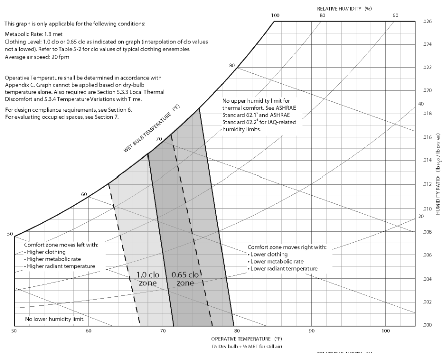
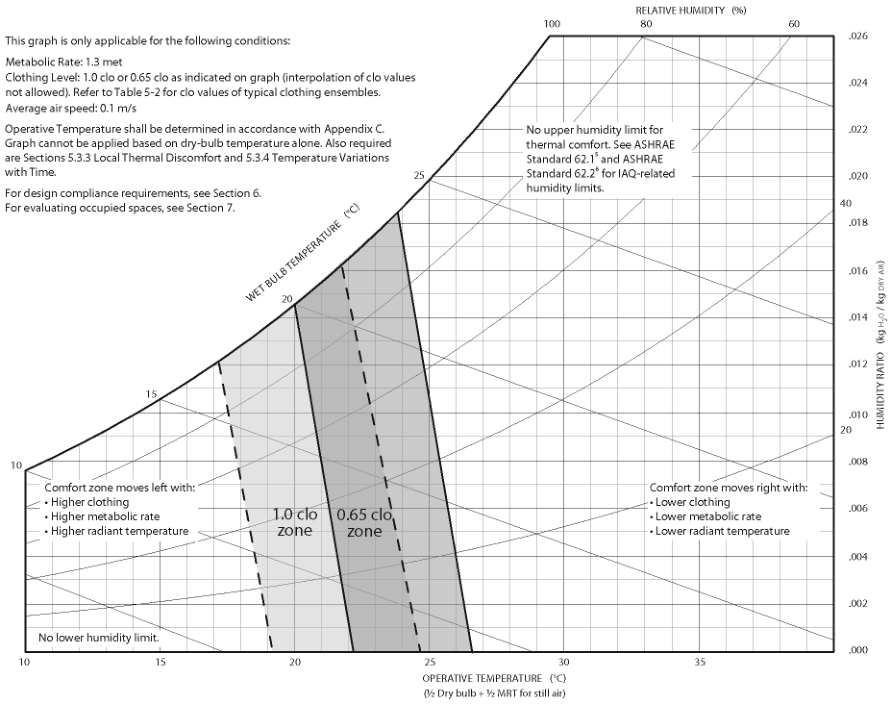
Figure 5-2 Comfort zone example—effect of increased clo value.
ANSI/ASHRAE Standard 55-2023 11
PDF Page 14
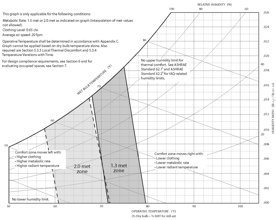
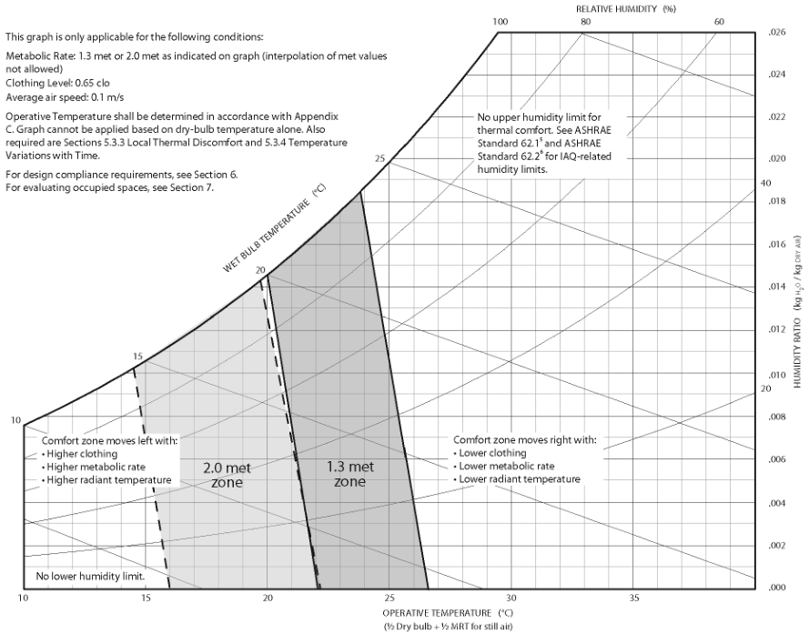
Figure 5-3 Comfort zone example—effect of increased met value.
12 ANSI/ASHRAE Standard 55-2023
PDF Page 15
Table 5-5 High-Performance (Low-e) Glazing Units
| Representative Occupant Distance from Interior Window or Shade Surface, ft (m) | Fraction of Body Exposed to Sun (f ), bes % | Glazing Unit Total Solar Transmission (T ), % sol | Glazing Unit Indirect SHGC (SHGC – T ), % sol | Interior Shade Openness Factor, % | Interior Shade Solar Absorptance of Window-Facing Side, % |
|---|---|---|---|---|---|
| 4.8 (1.5) | 50 | 35 | 4.5 | 9 | 65 |
| 5.1 (1.6) | 100 | 35 | 4.5 | 5 | 65 |
Table 5-6 Clear, Low-Performance Glazing Units
| Representative Occupant Distance from Interior Window or Shade Surface, ft (m) | Fraction of Body Exposed to Sun (f ), bes % | Glazing Unit Total Solar Transmission (T ), % sol | Glazing Unit Indirect SHGC (SHGC – T ), sol % | Interior Shade Openness Factor, % | Interior Shade Solar Absorptance of Window-Facing Side, % |
|---|---|---|---|---|---|
| 11.0 (3.3) | 50 | 83 | 10 | 1 | 25 |
| 14.5 (4.4) | 50 | 83 | 10 | 1 | 65 |
| 12.2 (3.7) | 100 | 83 | 10 | 1 | 25 |
| 15.9 (4.9) | 100 | 83 | 10 | 1 | 65 |
| Table 5-7 Tinted Glazing Units | Col2 | Col3 | Col4 | Col5 | Col6 |
|---|---|---|---|---|---|
| Representative Occupant Distance from Interior Window or Shade Surface, ft (m) | Fraction of Body Exposed to Sun (****fbes), % | Glazing Unit Total Solar Transmission (****Tsol), % | Glazing Unit Indirect SHGC (SHGC –****Tsol), % | Interior Shade Openness Factor, % | Interior Shade Solar Absorptance of Window-Facing Side, % |
| 5.3 (1.6) | 50 | 10 | 20 | 8 | 25 |
| 6.1 (1.9) | 50 | 10 | 20 | 1 | 65 |
| 5.9 (1.8) | 100 | 10 | 20 | 1 | 25 |
| 7.4 (2.3) | 100 | 10 | 20 | 1 | 65 |
| >7.3 (2.2) | 50 | <15 | 8 | No shade | No shade |
Table 5-8 Dynamic Glazing Units (Increasing Tsol Represents Decreasing Tint)
| Representative Occupant Distance from Interior Window or Shade Surface, ft (m) | Fraction of Body Exposed to Sun (f ), bes % | Glazing Unit Total Solar Transmission (T ), % sol | Glazing Unit Indirect SHGC (SHGC – T ), % sol | Interior Shade Openness Factor, % | Interior Shade Solar Absorptance of Window-Facing Side, % |
|---|---|---|---|---|---|
| 6.1 (1.9) | 50 | 0.5 | 10 | N/A | No shade |
| 6.1 (1.9) | 100 | 0.5 | 10 | N/A | No shade |
| 7.9 (2.4) | 50 | 3 | 10 | N/A | No shade |
| 9.5 (2.9) | 100 | 3 | 10 | N/A | No shade |
| 9.8 (3.0) | 50 | 6 | 10 | N/A | No shade |
| 10.3 (3.1) | 50 | 9 | 10 | N/A | No shade |
Table 5-9 Interior Shade Solar Absorptance Based on Color Description of Window-Facing Side of Shade
| Solar Absorptance, % | <15 | 15 to 25 | 25 to 65 | >65 |
|---|---|---|---|---|
| Color Description | White | Silver, cornsilk, wheat, oyster, beige, pearl | Beige, pewter, smoke, pebble, stone, pearl grey, light grey | Charcoal, graphite, chestnut |
ANSI/ASHRAE Standard 55-2023 13
PDF Page 16
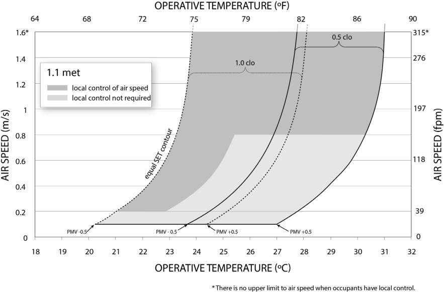
Figure 5-4 Satisfactory ranges of operative temperature to and average air speed Va for 1.0 and 0.5 clo comfort zones at humidity ratio 0.010.
Figure 5-5 provides a graphical example of comfort zones for two air speeds. Direct use of this chart to comply with the standard is allowable for the specific input conditions described on the chart.
Figure 5-6 describes the steps for determining the limits to air speed inputs. 5.3.4.1 Average Air Speed Va with Occupant Control. Section 5.3.4.2 does not apply when the occupants have control over average air speed Va and one of the following criteria is met:
a. One means of control exists for every six occupants or fewer. b. One means of control exists for every 84 m [2] (900 ft [2] ) or less. c. In multioccupant spaces where groups gather for shared activities, such as classrooms and conference
rooms, at least one control shall be provided for each space, regardless of size. Multioccupant spaces that are subdivided by movable walls shall have one control for each space subdivision.
5.3.4.2 Average Air Speed Va without Occupant Control. If occupants do not have control over the local air speed, meeting the requirements of Section 5.3.4.1, the following limits apply to the SET model and to Figure 5-4.
a. For operative temperatures to above 25.5°C (77.9°F), the upper limit to average air speed Va shall be 0.8
m/s (160 fpm). b. For operative temperatures to between 23.0°C and 25.5°C (73.4°F and 77.9°F), the upper limit to average
air speed Va shall follow an equal SET contour as described in Normative Appendix D. In Figure 5-4, this curve is shown between the dark and light shaded areas. It is permitted to determine the curve in Figure 5-4 by using the following equation:
Va = 50.49 – 4.4047( to ) + 0.096425( to ) [2] (m/s, °C)
Va = 31375.7 – 857.295( to ) + 5.86288( to ) [2] (fpm, °F)
c. For operative temperatures to below 23.0°C (73.4°F), the limit to average air speed Va shall be 0.2 m/s
(40 fpm). Exceptions to (c):
- Representative occupants with clothing insulation Icl greater than 0.7 clo.
- Representative occupants with metabolic rates above 1.3 met. Informative Note: These limits are shown by the light gray area in Figure 5-4.
14 ANSI/ASHRAE Standard 55-2023
PDF Page 17
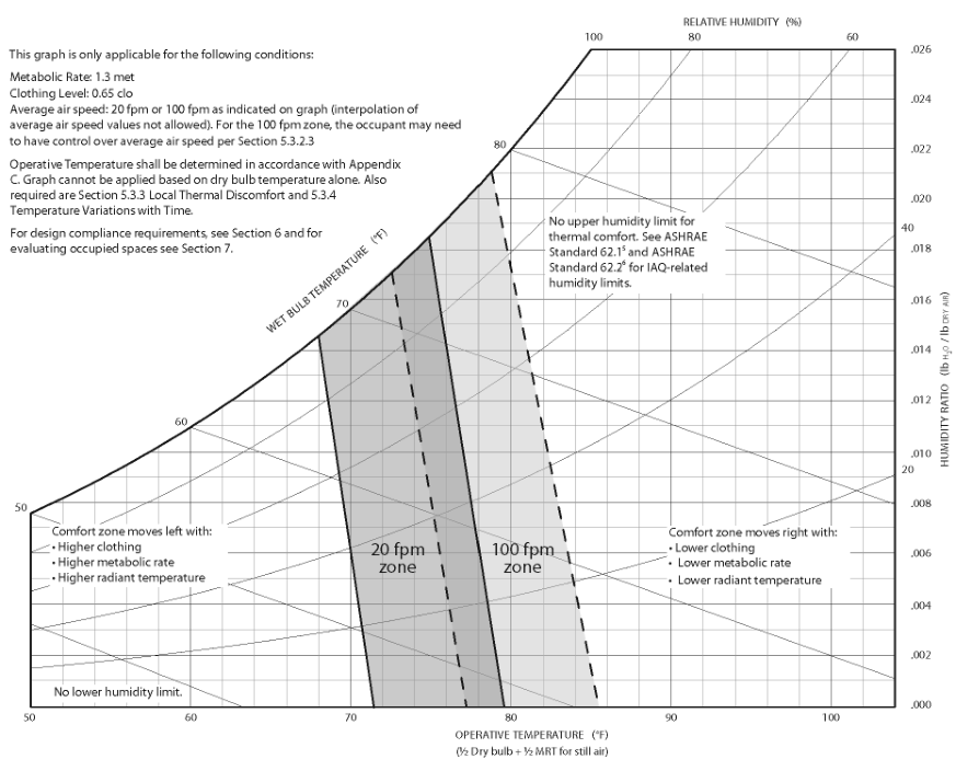
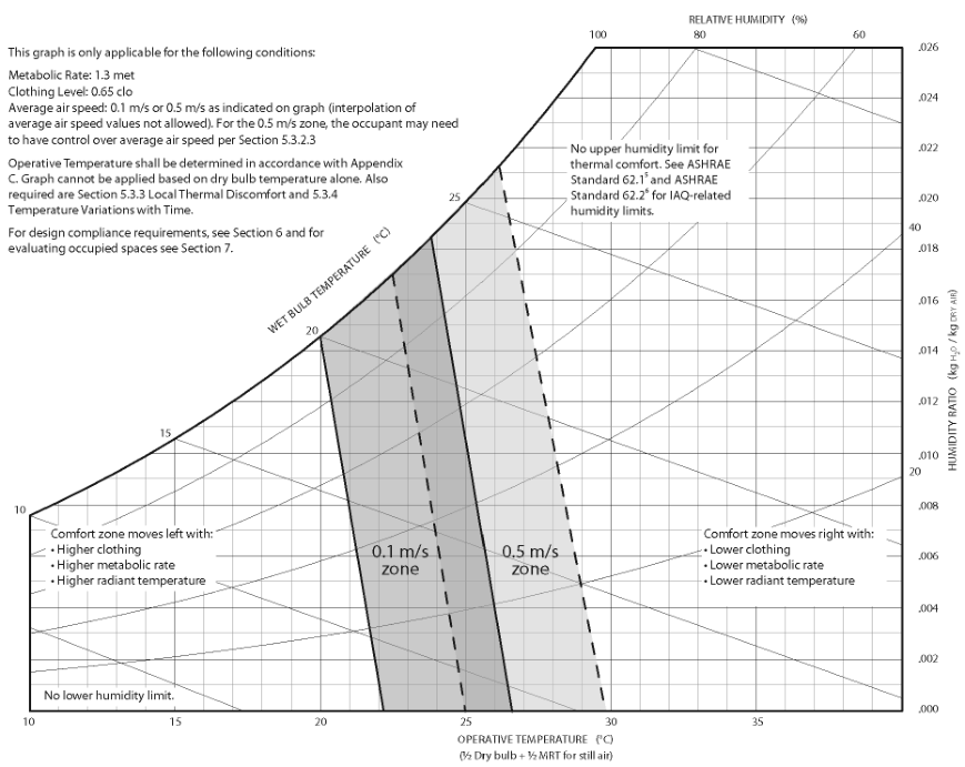
Figure 5-5 Elevated air speed comfort zone example (lightly shaded zone) compared to the still-air comfort zone example (darkly shaded zone).
ANSI/ASHRAE Standard 55-2023 15
PDF Page 18
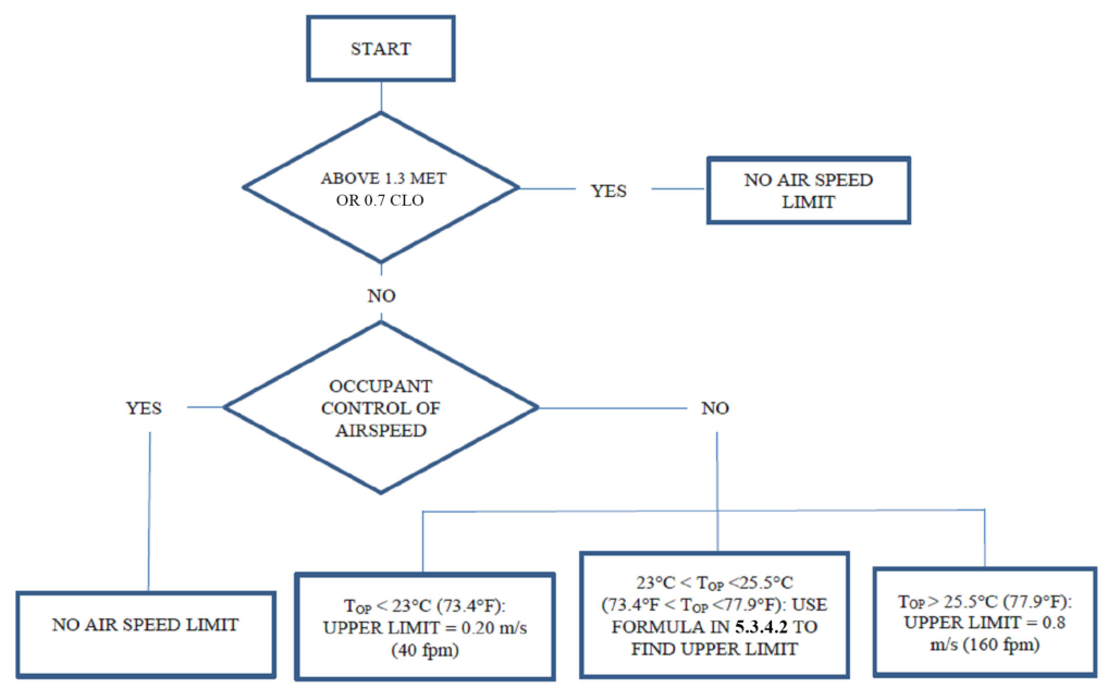
Figure 5-6 Flowchart for determining limits to air speed inputs in the elevated air speed comfort zone.
5.3.5 Local Thermal Discomfort 5.3.5.1 Applicability. The requirements specified in this section are required to be met only when representative occupants meet both of the following criteria:
a. Have clothing insulation Icl less than 0.7 clo b. Are engaged in physical activity with metabolic rates below 1.3 met
For the purpose of compliance with this section, representative occupants’ ankle level is 0.1 m (4 in.) above the floor, and head level is 1.1 m (43 in.) for seated occupants and 1.7 m (67 in.) for standing occupants. Informative Note: The standard does not contain requirements for standing occupants when all the repre sentative occupants are seated. Many standing occupants have met rates greater than 1.3 (see Section 5.2.1), and by criterion (b) above, the requirements of Section 5.3.5 do not apply to them. 5.3.5.2 Radiant Temperature Asymmetry. Radiant temperature asymmetry shall not exceed the values in Table 5-10. The radiant temperature asymmetry is quantified in its definition in Section 3.
When direct-beam solar radiation falls on a representative occupant, the radiant temperature asymmetry shall include the solar contribution as follows: The short-wave mean radiant temperature trsw, as determined in Normative Appendix C, shall be multiplied by two and added to the plane radiant temperature tpr for each horizontal or vertical direction in which the plane receives direct sunlight.
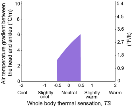
5.3.5.3 Ankle Air Speed. Air speed at 0.1 m (4 in.) above the floor shall be less than the value resulting from the following formula or in the shaded region of Figure 5-7:
Vankle < 0.35TS + 0.39 ( Vankle in m/s)
Vankle < 70.7TS + 79.6 ( Vankle in fpm)
where Vankle = air speed at 0.1 m (4 in.) above the floor TS = whole-body thermal sensation; equal to PMV calculated using the input air temperature and speed
16 ANSI/ASHRAE Standard 55-2023
PDF Page 19
Table 5-10 Allowable Radiant Temperature Asymmetry
Radiant Temperature Asymmetry °C (°F)
| Ceiling Warmer than Floor | Ceiling Cooler than Floor | Wall Warmer than Air | Wall Cooler than Air |
|---|---|---|---|
| <5 (9.0) | <14 (25.2) | <23 (41.4) | <10 (18.0) |
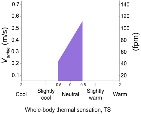
Figure 5-7 Air speed limits at 0.1 m (4 in.) above the floor as Figure 5-8 Vertical air temperature gradient limit as a func- a function of whole-body thermal sensation. tion of whole-body thermal sensation.
averaged over two heights: 0.6 m (24 in.) and 1.1 m (43 in.) for seated occupants and 1.1 m (43 in.) and 1.7 m (67 in.) for standing occupants Exception to 5.3.5.3: The requirement in this section does not apply when using elevated air speed in Sec tion 5.3.4. 5.3.5.4 Vertical Air Temperature Gradient. Air temperature gradient between head level and ankle level shall not exceed the value resulting from the following formula or in the shaded region of Figure 5-8.
T 7.82 - 0.87 TS - 1.91 [2] T in °C/m
T 4.29 - 0.48 TS - 1.91 [2] T in °F/ft
where
T = air temperature gradient between head and ankles, °C/m (°F/ft)
TS = whole-body thermal sensation. This is equal to the PMV calculated using the input air temperatures over two heights: 0.6 m (24 in.) and 1.1 m (43 in.) for seated occupants and 1.1 m (43 in.) and 1.7 m (67 in.) for standing occupants. Exception to 5.3.5.4: The requirement in this section does not apply when using elevated air speed in Sec tion 5.3.4. Informative Note: Refer to the informative note in Section 5.3.5.1.
5.3.5.5 Floor Surface Temperature. When representative occupants are seated with feet in contact with the floor, floor surface temperatures within the occupied zone shall be 19°C to 29°C (66.2°F to 84.2°F).
5.3.6 Temperature Variations with Time 5.3.6.1 Applicability. The fluctuation requirements of this section shall be met when they are not under the direct control of the individual occupant.
5.3.6.2 Cyclic Variations. Cyclic variations in operative temperature to that have a period not greater than 15 minutes shall have a peak-to-peak amplitude not greater than 1.1°C (2.0°F).
5.3.6.3 Drifts or Ramps. Monotonic, noncyclic changes in operative temperature to and cyclic variations with a period greater than 15 minutes shall not exceed the most restrictive requirements from Table 5-11. Informative Note: For example, the operative temperature shall not change more than 2.2°C (4.0°F) during
a 1.0 hour period and more than 1.1°C (2.0°F) during any 0.25 hour period within that 1.0 hour period.
ANSI/ASHRAE Standard 55-2023 17
PDF Page 20
Table 5-11 Limits on Temperature Drifts and Ramps
| Time Period, h | 0.25 | 0.5 | 1 | 2 | 4 |
|---|---|---|---|---|---|
| Maximum Operative Temperature****_to _Change Allowed, °C (°F) | 1.1 (2.0) | 1.7 (3.0) | 2.2 (4.0) | 2.8 (5.0) | 3.3 (6.0) |
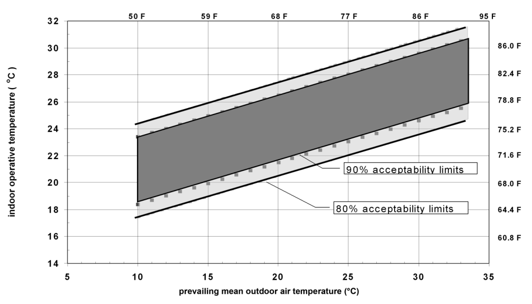
Figure 5-9 Acceptable operative temperature to ranges for naturally conditioned spaces.
5.4 Determining Acceptable Thermal Conditions in Occupant-Controlled Naturally Conditioned Spaces (Adaptive Model)
5.4.1 Applicability. This method defines acceptable thermal environments only for occupant-controlled naturally conditioned spaces that meet all of the following criteria:
a. There is no mechanical cooling system (e.g., refrigerated air conditioning, radiant cooling, or desiccant
cooling) or heating system in operation. b. Representative occupants have metabolic rates ranging from 1.0 to 1.5 met. c. Representative occupants are free to adapt their clothing to the indoor and/or outdoor thermal conditions
within a range at least as wide as 0.5 to 1.0 clo. d. The prevailing mean outdoor temperature is greater than 10°C (50°F) and less than 33.5°C (92.3°F).
5.4.2 Methodology. The allowable indoor operative temperatures to shall be determined from Figure 5-9
using the 80% acceptability limits or the equations in Section 5.4.2.2.
Informative Note: The 90% acceptability limits are included for information only. See Informative Infor
mative Appendix J for further guidance.
5.4.2.1 The prevailing mean outdoor air temperature t pma out shall be determined in accordance with
all of the following.
5.4.2.1.1 It shall be based on no fewer than seven and no more than 30 sequential days prior to the day in question.
5.4.2.1.2 It shall be a simple arithmetic mean of all of the mean daily outdoor air temperatures
tmda out of all the sequential days in Section 5.4.2.1.1.
Exception to 5.4.2.1.2: Weighting methods are permitted, provided that the weighting curve continually
decreases toward the more distant days such that the weight applied to a day is between 0.6 and 0.9 of
18 ANSI/ASHRAE Standard 55-2023
PDF Page 21
Table 5-12 Increases in Acceptable Operative Temperature Limits ( t 0) in Occupant-Controlled Naturally Conditioned Spaces (Figure 5-9) Resulting from Increasing Air Speed above 0.3 m/s (59 fpm)
Average Air Speed Va 0.6 m/s (118 fpm) 0.9 m/s (177 fpm) [1.2 m/s (236 fpm)]
1.2°C (2.2°F) 1.8°C (3.2°F) 2.2°C (4.0°F)
that applied to the subsequent day. For this option, the upper limit on the number of days in the sequence does not apply. (See Informative Appendix J for example calculation.) Mean daily outdoor air temperature tmda out for each of the sequential days in Section 5.4.2.1.1 shall be the simple arithmetic mean of all the outdoor dry-bulb temperature observations for the 24-hour day. The quantity of measurements shall be no less than two, and, in that case, shall be the minimum and maximum for the day. When using three or more measurements, the time periods shall be evenly spaced.
5.4.2.1.3 Observations in Section 5.4.2.1 shall be from the nearest approved meteorological station, public or private, or Typical Meteorological Year (TMY) weather file. Exception to 5.4.2.1.3: When weather data to calculate the prevailing mean outdoor air temperature
tpma out are not available, it is permitted to use as the prevailing mean the published meteorological
monthly means for each calendar month. It is permitted to interpolate between monthly means. 5.4.2.2 It shall be permitted to use the following equations, which correspond to the acceptable operative temperature to ranges in Figure 5-9:
Upper 80% acceptability limit (°C) = 0.31 tpma out + 21.3
Upper 80% acceptability limit (°F) = 0.31 tpma out + 60.5
Lower 80% acceptability limit (°C) = 0.31 tpma out + 14.3
Lower 80% acceptability limit (°F) = 0.31 tpma out + 47.9
5.4.2.3 The following effects are already accounted for in Figure 5-9 and the equations in Section 5.4.2.2 and, therefore, it is not required that they be separately evaluated: local thermal discomfort, clothing insulation Icl, metabolic rate, humidity, and air speed.
5.4.2.4 If t 0 > 25°C (77°F), then it shall be permitted to increase the upper acceptability temperature limits in Figure 5-9 and the equations in Section 5.4.2.2 by the corresponding t 0 in Table 5-12.
6. DESIGN COMPLIANCE
6.1 Design. Building systems (i.e., combinations of mechanical systems, control systems, and thermal enclosures) shall be designed to maintain occupied spaces at thermal conditions that provide thermal comfort in accordance with one of the methods in this standard, considering all expected operating conditions (i.e., peak and partial load).
Design compliance shall consider all predictable representative occupants and expected indoor and outdoor environmental conditions, including but not limited to
a. Seasonal and typical outdoor environmental variations b. Seasonal clothing changes of the representative occupants c. Short-term average air temperature variability due to HVAC system design and operations including
thermostat deadband and cycling d. Indoor spatial variations in average air temperature, relative humidity, average air speed, and mean radi ant temperature, including the presence, or lack thereof, of direct solar radiation
6.1.1 Design Thermal Environmental Control Classification. For all projects demonstrating compliance through Section 5.3, design compliance shall indicate the Thermal Environmental Control Classification Level in accordance with Table 6-1 of each space type within the building.
Each control measure for environmental factors shall be readily accessible to occupants, when occupancy is expected and be either (a) or (b) as follows:
a. A user-adjustable thermostat with ability of the user to change set point by ±3°C (±5°F) b. Capable of changing the thermal environment of the space or individual occupant by the magnitude
specified in either Section 6.1.1(a) or (b) in 15 minutes or less from occupant control initiation while met and clo values are constant. For control measures that apply to a multioccupant space, the change must meet the requirements for all representative occupants.
ANSI/ASHRAE Standard 55-2023 19
PDF Page 22
Table 6-1 Thermal Environmental Control Classification Levels
| Thermal Environmental Control Classification Level | Control Measure(s) for Environmental Factors Required to Achieve Level | Informative Examples Meeting Thermal Environmental Control Classification Levels |
|---|---|---|
| 1 | Each occupant is provided two or more control measures for their personal environment. | • Private office with a ceiling fan and an occupant adjustable thermostat • Shared office with desktop fans and foot warmers for each occupant |
| 2 | Each occupant is provided one control measure for their personal environment. | • Private office with an occupant adjustable thermostat • Shared office with a desktop fan for each occupant |
| 3 | The room or thermal zone provides multioccupant control of at least two control measures in their shared environment. | • Shared office with an occupant adjustable thermostat and ceiling fan control |
| 4 | The room or thermal zone provides multioccupant control of one control measure in their shared environment. | • Shared office with an occupant adjustable thermostat |
| 5 | No occupant control of any environmental factors | • Shared or private office with an unadjustable thermostat or no thermostat |
Table 6-2 Prescriptively Compliant Personal Comfort Systems
| Col1 | Cooling |
|---|---|
| Desk fan aimed at head/face/upper body | Capable of providing air speed at the occupant’s head/face/upper body within range of 0.36 to 0.8 m/s (70.9 to 157.5 fpm) |
| Cooled chair | Capable of extracting 20 W from the body |
| Col1 | Heating |
|---|---|
| Footwarmer | Capable of adding 6 W to the body |
| Heated chair | Capable of adding 14 W to the body |
- Cooling: At design cooling condition, the measure shall change PMV by –0.5 or i. average air temperature by –3°C (–5 °F). ii. average air speed by +0.3 m/s (60 fpm). iii. mean radiant temperature by –3°C (–5 °F). iv. for personal comfort systems (PCSs), the measure shall be listed in Table 6-2 or have a minimum
corrective power of –2°C (–4°F). 2. Heating: At design heating condition, the measure shall change PMV by +0.5 or i. average air temperature by +3°C (5°F). ii. mean radiant temperature by +3°C (5°F). iii. for PCSs, the measure shall be listed in Table 6-2 or have a minimum corrective power of +2°C
(4°F). Informative Note: A single device that is capable of changing PMV in both directions ([a] and [b]) is
counted as a single control measure. For example, a thermostat that can affect the temperature in the space by –0.5 and +0.5 PMV counts as one control measure not two. 6.2 Documentation. The method and design conditions appropriate for the intended use of the building shall be selected and documented as specified in Sections 6.2.1, 6.2.2, and 6.2.3.
6.2.1 Core Documentation Requirements (applies to both Section 5.3 and Section 5.4)
a. Each unique space shall be documented. Spaces excluded from compliance documentation shall be
clearly identified as such along with the rationale for their exclusion (e.g., not regularly occupied). b. The method of design compliance shall be stated: Section 5.3 or Section 5.4. c. Each representative occupant and their location within the space shall be defined, including their cloth ing insulation ( Icl ) and metabolic rate ( met ) for each design comfort condition. Where Table 5-1 gives a
20 ANSI/ASHRAE Standard 55-2023
PDF Page 23
range, the basis for selecting a single value within that range shall be stated. If any occupants are deemed nonrepresentative, they shall be identified along with the rationale for their exclusion. d. Describe the design comfort conditions. These conditions are specific combinations of indoor and out door factors at which occupant thermal comfort shall be evaluated. Design comfort conditions shall be chosen to cover the most challenging thermal comfort scenarios likely experienced by the occupant, including the possible impact of direct solar radiation. Each unique combination of space and representative occupant shall be evaluated at a minimum of two design comfort conditions: cooling and heating. ( Informative Note: The design comfort conditions may not align with system or room peak heating and cooling load conditions and should be considered carefully by the designer—e.g. evaluating direct beam solar on an occupant in a perimeter room during winter.) e. State the operative temperature to, including expected ranges, used in the comfort calculation for each
combination of space, representative occupant, and design comfort condition. f. When direct-beam solar radiation falls on a representative occupant, documentation shall include the method in Section 5.3.3 used for compliance and associated documentation for the chosen method. The calculation inputs, methods, and results shall be stated where applicable. g. Thermal environmental control classification level shall be documented for each unique space, indicat ing the control measure(s) for environmental factors, the means of control, and the degree to which control changes the environmental factor. h. State compliance, or lack thereof, for each combination of space, representative occupant, and design
comfort condition.
6.2.2 Section 5.3 Specific Documentation
a. State the relative humidity and average air speed Va, including expected ranges, used in the comfort cal culation for each combination of space, representative occupant, and design comfort condition. b. Local thermal discomfort shall be addressed, at a minimum, by a narrative explanation of why an effect
is not likely to exceed Section 5 limits. Where calculations are used to determine the effect of local thermal discomfort in accordance with Section 5, the calculation inputs, methods, and results shall be stated. c. Where elevated air speed with occupant control is employed to provide satisfactory thermal conditions,
documentation shall be provided to identify the method and equipment for occupant control.
6.2.3 Section 5.4 Specific Documentation
a. State compliance time period(s) for Section 5.4 applicability. ( Informative Note: This could be select
months of the year or periods of outdoor thermal conditions when a mixed-mode system changes to natural ventilation mode.) b. State prevailing mean outdoor design temperature for each compliance time period and confirmation it is
within the bounds of Section 5.4. c. Confirm that no heating or cooling system is in operation during the compliance time period(s). d. Confirm that representative occupant metabolic rates are within the bounds of Section 5.4. e. Confirm that occupants are freely able to alter their clothing as required by Section 5.4. f. State predicted operative temperature range during occupied hours for each compliance time period, considering the dynamic performance of the space, meteorological weather data, and the effects of direct solar radiation on mean radiant temperature. g. State increased air speed adjustment to upper operative temperature limit based on Table 5-12, if applicable.
Informative Note: A sample compliance form can be downloaded at www.ashrae.org/55Files (requires
Microsoft Excel [®] .
7. EVALUATION OF COMFORT IN EXISTING BUILDINGS
7.1 Introduction. Evaluation of comfort in existing buildings is not a requirement of this standard. When such evaluation is otherwise required (e.g., by code or another standard) use one of the following methods:
7.1.1 Occupant surveys using Sections 7.2.1, 7.3.1, or 7.4.1. 7.1.2 Environmental measurement using Sections 7.2.2, 7.3.2, 7.3.3, 7.3.4, or 7.4.2. 7.1.3 When using the building automation system as an adjunct to Sections 7.1.1 or 7.1.2, it shall have the characteristics described in Section 7.3.5. 7.2 Criteria for Comfort in Existing Buildings 7.2.1 Comfort Determination from Occupant Surveys. Satisfaction is directly determined from the responses of occupants using the scales and comfort limits described in Section 7.3.1.
7.2.2 Prediction of Comfort from Environmental Measurements
ANSI/ASHRAE Standard 55-2023 21
PDF Page 24
7.2.2.1 Mechanically Conditioned Spaces. Use Section 5.3 to determine the comfort of occupants under the measured environmental conditions. Clothing and activity levels of the occupants must be as observed or as expected for the use of the indoor space in question. Use Section 5.3.4 to adjust the comfort zone’s lower and upper operative temperature limits for elevated air movement. Occupied zone conditions must also conform to requirements for avoiding local thermal discomfort (as specified in Section 5.3.5) and to limits to rate of temperature change over time, as specified in Section 5.3.6.
Parameters to be measured and/or recorded include the following:
a. Occupant metabolic rate (met) and clothing (clo) observations b. Air temperature and humidity c. Mean radiant temperature tr, unless it can be otherwise demonstrated that, within the space, tr is within 1°C (2°F) of ta d. Air speed, unless it can be otherwise demonstrated that, within the space, average air speed Va meets the
tr, unless it can be otherwise demonstrated that, within the space, tr
requirements of Section 5.3.4 e. Control measures for environmental factors
7.2.2.2 Occupant-Controlled Naturally Conditioned Spaces. Section 5.4 prescribes the use of the adaptive model for determining the comfort zone boundaries. The air movement extensions to the comfort zone’s lower and upper operative temperature limits (Table 5-12) shall be used when elevated air movement is present.
Parameters to be measured include the following:
a. Indoor air temperature and mean radiant temperature b. Outdoor air temperature
tr
7.3 Measurement Methods 7.3.1 Surveys of Occupant Responses to Environment. Surveys shall be solicited from the entire occupancy or a representative sample thereof. If more than 45 occupants are solicited, the response rate must exceed 35%. If solicited occupants number between 20 and 45, at least 15 must respond. For under 20 solicited occupants, 80% must respond. Informative Note: Refer to Informative Appendix L for further discussion of surveys, including examples.
7.3.1.1 Satisfaction Surveys
a. Thermal satisfaction shall be measured with a scale ending with the choices “very dissatisfied” and “very
satisfied.” b. Thermal satisfaction surveys shall include diagnostic questions allowing causes of dissatisfaction to be
identified.
7.3.1.2 Point-in-Time Surveys. Point-in-time surveys shall be solicited during times representative of the building’s occupancy.
a. Thermal satisfaction questions shall include a continuous or seven-point scale ending with the choices
“very dissatisfied” and “very satisfied.” b. Thermal sensation questions shall include the ASHRAE seven-point thermal sensation scale subdivided
as follows: cold, cool, slightly cool, neutral, slightly warm, warm, hot. c. Thermal preference questions shall use the three-point scale “cooler,” “without change,” and “warmer.”
7.3.2 Physical Measurement Positions within the Building
a. Floor plan: Thermal environment measurements shall be made in the building at a representative sample
of locations where the occupants are known to, or are expected to, spend their time. When performing evaluation of similar spaces in a building, it shall be permitted to select a representative sample of such spaces.
If occupancy distribution cannot be observed or estimated, the measurement locations shall include both of the following:
- The center of the room or space
- 1.0 m (3.3 ft) inward from the center of each of the room’s walls. In the case of exterior walls with windows, the measurement location shall be 1.0 m (3.3 ft) inward from the center of the largest window. Measurements shall also be taken in locations where the most extreme values of the thermal parameters are observed or estimated to occur (e.g., potentially occupied areas near windows, diffuser outlets, corners, and entries).
22 ANSI/ASHRAE Standard 55-2023
PDF Page 25
Table 7-1 Instrumentation Measurement Range and Accuracy
| Quantity | Measurement Range | Accuracy |
|---|---|---|
| Air temperature | 10°C to 40°C (50°F to 104°F) | ±0.2°C (0.4°F) |
| Mean radiant temperature | 10°C to 40°C (50°F to 104°F) | ±1°C (2°F) |
| Plane radiant temperature | 0°C to 50°C (32°F to 122°F) | ±0.5°C (1°F) |
| Surface temperature | 0°C to 50°C (32°F to 122°F) | ±1°C (2°F) |
| Humidity, relative | 25% to 95% rh | ±5% rh |
| Air speed | 0.05 to 2 m/s (10 to 400 fpm) | ±0.05 m/s (±10 fpm) |
| Directional radiation | –35 W/m2 to +35 W/m2 (–11 Btu/h·ft2 to +11 Btu/h·ft2) | ±5 W/m2 (±1.6 Btu/h·ft2) |
b. Height above floor: Air temperature and average air speed Va shall be measured at the 0.1, 0.6, and 1.1 m
(4, 24, and 43 in.) levels for seated occupants at the plan locations specified in Section 7.3.2(a)(1) and Section 7.3.2(a)(2). Measurements for standing occupants shall be made at the 0.1, 1.1, and 1.7 m (4, 43, and 67 in.) levels, and measurements for horizontal occupants shall be made at the mean height of the body. Operative temperature to or PMV shall be measured or calculated at the 0.6 m (24 in.) level for seated occupants, the 1.1 m (43 in.) level for standing occupants, and the mean height of the body for horizontal occupants. Floor temperature that may cause local discomfort shall be measured at the surface by contact thermometer or infrared thermometer (Section 5.3.5.5).
Radiant temperature asymmetry that may cause local thermal discomfort (Section 5.3.5.2) shall be measured in the affected occupants’ locations, with the sensor oriented to capture the greatest surface temperature difference. 7.3.3 Timing of Physical Measurements. Measurement periods shall span two hours or more and, in addition, shall represent a sample of the total occupied hours in the period selected for evaluation (year, season, or typical day) or shall take place during periods directly determined to be the critical hours of anticipated occupancy.
Measurement intervals for air temperature, mean radiant temperature tr, and humidity shall be five minutes or less, and for air speed shall be three minutes or less.
Assessment of control measures for occupant control of environmental factors shall be evaluated for compliance with the requirements of Section 6.1.1, including accessibility, time response, and magnitude of PMV influence.
7.3.4 Physical Measurement Device Criteria. The measuring instrumentation used shall meet the requirements for measurement range and accuracy given in Table 7-1. Air temperature sensors shall be shielded from radiation exchange with the surroundings.
7.3.5 Measurements from Building Automation System (BAS) 7.3.5.1 Location. BAS space sensor locations shall be evaluated against the location criteria in Section 7.3.2. 7.3.5.2 Precision. BAS space temperature sensor accuracy shall be 0.5°C (1°F) or less, and space humidity sensor accuracy shall be ±5% rh.
7.3.5.3 Trending Capabilities. The BAS shall have the ability to trend space temperature data at intervals not exceeding 15 minutes over 30 days or longer.
7.3.5.4 Additional Concurrent Data. Data such as equipment status, supply and return air, and water temperatures shall be observed for time periods concurrent with the space temperature data. 7.4 Evaluation Methods 7.4.1 Evaluation Based on Survey Results
a. The percentage of occupants satisfied shall be calculated from seven-point satisfaction survey scores by
dividing the number of votes falling between +1 and +3, inclusive, by the total number of votes. Responses to diagnostic dissatisfaction questions shall be tallied by category. b. For point-in-time surveys, comfort shall be evaluated using votes on the satisfaction and/or thermal sen sation scales. On the satisfaction scale, votes between +1 (slightly satisfied) and +3 (very satisfied), inclusive, shall be divided by total votes to obtain the percentage of thermal satisfaction observed during the survey period. On the seven-point thermal sensation scale, votes between –1 and +1, inclusive, shall be divided by total votes to obtain the percentage of thermal satisfaction observed during the survey period.
ANSI/ASHRAE Standard 55-2023 23
PDF Page 26
7.4.2 Evaluation Based on Physical Measurements of the Thermal Environment. Use one of the following approaches in Section 7.4.2.1 or 7.4.2.2.
7.4.2.1 Approaches to Predicting whether a Thermal Environment is Satisfactory at a Specific Instance in Time
a. Mechanically conditioned buildings:
-
Occupied spaces shall be evaluated using the PMV comfort zone as defined in Section 5.3.
-
Local thermal discomfort shall be evaluated using the limits to environmental asymmetry prescribed in Section 5.3.5. b. Buildings with occupant-controlled operable windows:
-
Occupied spaces shall be evaluated using the indoor operative temperature to contours of the adaptive model comfort zone in Section 5.4, including the contour extensions for average air speeds Va above 0.3 m/s (59 fpm). 7.4.2.2 Approaches to Predicting whether a Thermal Environment is Satisfactory over Time. Section 7.4.2.2.1 shall be used to quantify the number of hours in which environmental conditions are outside the comfort zone requirements during occupied hours in the time period of interest. Exceedance is measured by exceedance hours (EH) ( Informative Note: See definition in Section 3). Section 7.4.2.2.2 is permitted but not required to be used with Section 7.4.2.2.1.
7.4.2.2.1 EH is calculated for the PMV comfort zone and adaptive model comfort zone as follows:
a. Letting each sum be over occupied hours within the specified period, and comfort indices respective to
that hour, for PMV comfort zone, EH = Hdisc, where Hdisc is a discomfort hour; Hdisc = 1 if | PMV | – 0.5
- 0 and 0 otherwise. b. For adaptive model comfort zone, where H>upper and H<lower are discomfort hours outside of comfort
zone boundaries tupper and tlower, EH = ( H>upper + H<lower ), where H>upper = 1 if top - tupper and 0 otherwise, and H<lower = 1 if top < tlower and 0 otherwise. c. Units are in hours. Exceedance hours can also be expressed as a probability by dividing EH by total
occupied hours.
7.4.2.2.2 It is permissible to quantify the expected number of episodes of discomfort, rate-of-change exceedances, and local discomfort exceedances, within a time period of interest.
8. REFERENCES
- ASHRAE. 2021. ASHRAE Handbook—Fundamentals. Peachtree Corners, GA: ASHRAE.
- ASHRAE. 2022. ANSI/ASHRAE/IES Standard 90.1, Energy Standard for Buildings Except Low-Rise Residential Buildings. Peachtree Corners, GA: ASHRAE.
- Tartarini, F., S. Schiavon, T. Cheung, and T. Hoyt. 2020. CBE Thermal Comfort Tool: Online Tool for Thermal Comfort Calculations and Visualizations. SoftwareX 12 (July 2020):100563. https://doi.org/ 10.1016/j.softx.2020.100563.
- Blum, H.F. 1945. Solar heat load, its relationship to the total heat load, and its relative importance in the design of clothing. Journal of Clinical Investigation 24:712–21.
- ASHRAE. 2022. ANSI/ASHRAE Standard 62.1, Ventilation and Acceptable Indoor Air Quality . Peachtree Corners, GA: ASHRAE.
- ASHRAE. 2022. ANSI/ASHRAE Standard 62.2, Ventilation and Acceptable Indoor Air Quality in Resi- dential Buildings . Peachtree Corners, GA: ASHRAE.
24 ANSI/ASHRAE Standard 55-2023
PDF Page 27
(This is a normative appendix and is part of this standard.)
NORMATIVE APPENDIX A OPERATIVE TEMPERATURE AND PROCEDURE FOR SECTION 5.3
A1. METHODS FOR DETERMINING OPERATIVE TEMPERATURE
Determine operative temperature to using the following method or ASHRAE Handbook—Fundamentals [ 1], Chapter 9. Informative Note: Average air speed and average air temperature have precise definitions in this standard.
See Section 3 for all defined terms. Operative temperature to is permitted to be calculated per the following formula:
to = Ata + 1 - A tr
where to = operative temperature ta = average air temperature
tr = mean radiant temperature ( Informative Note: For detailed calculation procedures, see the “Thermal
Comfort” chapter of the most current edition of ASHRAE Handbook—Fundamentals .)
A can be selected from the following values as a function of the average air speed Va .
A2. PROCEDURE FOR DETERMINING SATISFACTORY THERMAL ENVIRONMENT IN OCCUPIED SPACES PER SECTION 5.3
The predicted mean vote model with adjustments for solar radiation and elevated air speed is used to determine the boundaries of the comfort zone per the calculation methods described in Normative Appendix B through Normative Appendix D. These calculation methods are incorporated in the Thermal Comfort Tool [3] . The flowchart in Figure A-1 provides the procedure for how these calculation methods should be applied.
Figure A-1 Flowchart describing process of calculation methods used in Section 5.3.
ANSI/ASHRAE Standard 55-2023 25
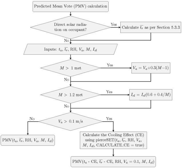
PDF Page 28
(This is a normative appendix and is part of this standard.)
NORMATIVE APPENDIX B COMPUTER PROGRAM FOR CALCULATION OF PREDICTED MEAN VOTE (PMV)
The following code is one implementation of the PMV calculation using JavaScript in SI units. This calculation does not include discomfort risk due to local discomfort factors. The input variable “clo” in the PMV function shall be calculated using the following equation:
clo = Icl × (0.6 + 0.4/ M ) for M 1.2
clo = Icl for M < 1.2
where M is the metabolic rate in met units and Icl is the clothing insulation.
The input variable Vel in the PMV function is the sum of the average air speed ( V ) plus the activitygenerated air speed ( Vag ) caused by motion of individual body parts (m/s). It is a function of metabolic rate and is added to the average air speed to determine convective cooling of the body. Vag is assumed to be 0 for metabolic rates equal and lower than 1 met and otherwise equal to
for M - 1 met.
pmv = function(ta, tr, vel, rh, met, clo, wme) { /*
returns [pmv, ppd] ta, air temperature (°C) tr, mean radiant temperature (°C) vel, average air speed (Va)+ activity-generated air speed (Vag)(m/s) rh, relative humidity (%) Used only this way to input humidity level met, metabolic rate (met) clo, clothing (clo) wme, external work, normally around 0 (met) */ var pa, icl, m, w, mw, fcl, hcf, taa, tra, tcla, p1, p2, p3, p4, p5, xn, xf, eps, hcn, hc, tcl, hl1, hl2, hl3, hl4, hl5, hl6, ts, pmv, ppd, n;
pa = rh * 10 * exp(16.6536 – 4030.183 / (ta + 235)); icl = 0.155 * clo; //Thermal insulation of the clothing in M2K/W m = met * 58.15; //Metabolic rate in W/M2 w = wme * 58.15; //External work in W/M2 mw = m – w; //Internal heat production in the human body
if (icl <= 0.078) fcl = 1 + (1.29 * icl); else fcl = 1.05 + (0.645 * icl);
//Heat transf. coeff. by forced convection hcf = 12.1 * sqrt(vel); taa = ta + 273; tra = tr + 273; tcla = taa + (35.5 – ta) / (3.5 * icl + 0.1); p1 = icl * fcl; p2 = p1 * 3.96; p3 = p1 * 100; p4 = p1 * taa; p5 = 308.7 – 0.028 * mw + p2 * pow(tra / 100, 4); xn = tcla / 100; xf = tcla / 50; eps = 0.00015; n = 0;
while (abs(xn – xf) > eps) {
xf = (xf + xn) / 2;
26 ANSI/ASHRAE Standard 55-2023
PDF Page 29
hcn = 2.38 * pow(abs(100.0 * xf – taa), 0.25); if (hcf > hcn) hc = hcf; else hc = hcn; xn = (p5 + p4 * hc – p2 * pow(xf, 4)) / (100 + p3 * hc);
++n; if (n > 150) { alert(‘Max iterations exceeded’); return 1; } } tcl = 100 * xn – 273;
//Heat loss diff. through skin hl1 = 3.05 * 0.001 * (5733 – (6.99 * mw) – pa);
//Heat loss by sweating if (mw > 58.15) hl2 = 0.42 * (mw – 58.15); else hl2 = 0;
//Latent respiration heat loss hl3 = 1.7 * 0.00001 * m * (5867 – pa);
//Dry respiration heat loss hl4 = 0.0014 * m * (34 – ta);
//Heat loss by radiation hl5 = 3.96 * fcl * (pow(xn, 4) – pow(tra / 100, 4));
//Heat loss by convection hl6 = fcl * hc * (tcl – ta); ts = 0.303 * exp(–0.036 * m) + 0.028; pmv = ts * (mw – hl1 – hl2 – hl3 – hl4 – hl5 – hl6); ppd = 100.0 – 95.0 * exp(–0.03353 * pow(pmv, 4.0) – 0.2179 * pow(pmv,
2.0));
var r = {} r.pmv = pmv; r.ppd = ppd; return r }
Validation Table
| Run | Air Temp. | Col3 | RH | Radiant Temp. | Col6 | Air Speed | Col8 | met | clo | PMV |
|---|---|---|---|---|---|---|---|---|---|---|
| # | ** °F** | C | % | °F | C | fpm | m/s | m/s | m/s | m/s |
| 1 | 67.3 | 19.6 | 86 | 67.3 | 19.6 | 20 | 0.10 | 1.1 | 1 | –0.47 |
| 2 | 75.0 | 23.9 | 66 | 75.0 | 23.9 | 20 | 0.10 | 1.1 | 1 | 0.48 |
| 3 | 78.2 | 25.7 | 15 | 78.2 | 25.7 | 20 | 0.10 | 1.1 | 1 | 0.53 |
| 4 | 70.2 | 21.2 | 20 | 70.2 | 21.2 | 20 | 0.10 | 1.1 | 1 | –0.48 |
| 5 | 74.5 | 23.6 | 67 | 74.5 | 23.6 | 20 | 0.10 | 1.1 | 0.5 | –0.47 |
| 6 | 80.2 | 26.8 | 56 | 80.2 | 26.8 | 20 | 0.10 | 1.1 | 0.5 | 0.52 |
| 7 | 82.2 | 27.9 | 13 | 82.2 | 27.9 | 20 | 0.10 | 1.1 | 0.5 | 0.50 |
| 8 | 76.5 | 24.7 | 16 | 76.5 | 24.7 | 20 | 0.10 | 1.1 | 0.5 | –0.49 |
Note: In every case listed above, the PMV result corresponds to a calculated PPD of 10%.
ANSI/ASHRAE Standard 55-2023 27
PDF Page 30
(This is a normative appendix and is part of this standard.)
NORMATIVE APPENDIX C PROCEDURE FOR CALCULATING COMFORT IMPACT OF SOLAR GAIN ON OCCUPANTS
C1. CALCULATION PROCEDURE
Solar gain to the human body is calculated using the effective radiant field (ERF), a measure of the net radiant energy flux to or from the human body ( ASHRAE Handbook—Fundamentals [ 1], Chapter 9). ERF is expressed in W/m [2] (Btuh/ft [2] ), where “area” refers to body surface area. The surrounding surface temperatures of a space are expressed as mean radiant temperature tr, which equals long-wave mean radiant temperature trlw when no solar radiation is present. The ERF on the human body from long-wave exchange with surfaces is related to t by
ace are expressed as mean radiant temperature tr
trlw when no solar r
trlw
ERF = feff hr trlw - ta
(C-1)
where feff is the fraction of the body surface exposed to radiation from the environment (= 0.696 for a seated person and 0.725 for a standing or horizontal person), hr is the radiation heat transfer coefficient (W/m [2] ·K
[Btuh/ft [2] ·°F]), and ta is the air temperature (°C [°F]).
The energy flux actually absorbed by the body is ERF times the long-wave absorptivity LW of skin and clothing (0.95 is the default value for skin and clothing).
Solar radiation absorbed on the body’s surface can be equated to an additional amount of long-wave flux, ERF solar :
LW ERF solar = SWEsolar
(C-2)
where Esolar is the short-wave solar radiant flux on the body surface (W/m [2] [Btuh/ft [2] ]) and SW is shortwave absorptivity.
Esolar is the sum of three fluxes that have been filtered by fenestration properties and geometry and are distributed on the occupant body surface: diffuse solar energy coming from the sky vault ( Ediff ), solar energy reflected upward from the floor ( Erefl ), and direct-beam solar energy coming directly from the sun ( Edir ). These fluxes are defined below.
Ediff = 0.5 feff fsvvTsol Idiff
(C-3)
where fsvv is the fraction of sky vault in the occupant’s view (see Figure C-1); Idiff is diffuse sky irradiance received on an upward-facing horizontal surface (W/m [2] [Btuh/ft [2] ]); and Tsol is the total solar transmittance, the ratio of incident short-wave radiation to the total short-wave radiation passing through the glazing unit and shades of a window system.
The reflected radiation from natural and built surfaces protruding above the horizon is assumed to equal the Idiff they have blocked.
The total outdoor solar radiation on the horizontal is filtered by both Tsol and fsvv and multiplied by the reflectance of the floor and lower furnishings Rfloor .
Erefl = 0.5 feff fsvvTsol ITH Rfloor
(C-4)
where ITH is the total horizontal direct and diffuse irradiance outdoors (W/m [2 ] [Btuh/ft [2] ]), and the floor reflectance Rfloor is 0.6.
Direct radiation is incident only on the projected fraction of the body fp, which depends on solar altitude , the sun’s horizontal angle relative to the front of the person (SHARP), and posture (seated, standing, horizontal). The fp values are tabulated in the computer program in Section C4.
The direct radiation is also reduced by any shading of the body provided by the indoor surroundings, quantified by the body exposure fraction fbes (see Figure C-2).
Edir = fp feff fbes Tsol Idir
(C-5)
Idir is the direct-beam (normal) solar radiation (W/m [2 ] [Btuh/ft [2] ]). The meteorological radiation parameters are related as follows:
ITH = Idir sin + Idiff Idiff is approximated as (0.2 Idir).
ERF solar is therefore calculated from the following equation:
ERF solar = 0.5 fsvv Idiff + 0.6 ITH + fp fbes Idir feff Tsol SW LW
(C-6)
28 ANSI/ASHRAE Standard 55-2023
PDF Page 31
To obtain ERF solar with Equation C-6 and the fixed default values given above, the required inputs are fsvv, Idir, fbes, Tsol, SW, , posture, and the sun’s horizontal angle relative to person (SHARP). These are described further in Section C2.
ERF solar is converted to short-wave mean radiant temperature trsw using Equation C-1.
C2. INPUTS TO CALCULATION PROCEDURE
The calculation requires eight input values as listed in Table C-2 and explained below.
a. Short-wave absorptivity SW : The short-wave absorptivity of the occupant will range widely, depending
on the color of the occupant’s skin as well as the color and amount of clothing covering the body. A value of 0.7 shall be used unless more specific information about the clothing or skin color of the occupants is available. ( Informative Note: Short-wave absorptivity typically ranges from 0.57 to 0.84, depending on skin and clothing color. More information is available in Blum [ 4] . b. Sky-vault view fraction fsvv : The sky-vault view fraction ranges between 0 and 1 as shown in Table C-3. It
is calculated with Equation C-7 for windows to one side. This value depends on the dimensions of the window (width w, height h ) and the distance d between the occupant and the window.
fsvv
tan– [1] ---- h - tan– [1] ---- w - 2 d 2 d
= ------------------------------------------------90 180
(C-7)
where the arctan function returns values in degrees. When calculating fsvv for multiple windows, the fsvv for each may be calculated and summed to obtain a total fsvv . Exterior objects obstructing the sky vault shall not be considered because they have a similar diffuse reflectivity as the sky vault. c. Total solar transmittance Tsol : The total solar transmittance of window systems, including glazing unit,
blinds, and other façade treatments, shall be determined using one of the following methods:
- Glazing unit Tsol shall be provided by manufacturer or from the National Fenestration Rating Council approved Lawrence Berkeley National Lab International Glazing Database.
- Glazing unit plus interior fabric shade shall be calculated as the product of glazing unit Tsol (in item C2[a]) multiplied by the shade openness factor.
- Glazing unit plus venetian blinds or other complex or unique shades shall be calculated using National Fenestration Rating Council approved software or Lawrence Berkeley National Lab Complex Glazing Database.
When direct solar radiation that falls on a representative occupant is transmitted through more than one window system with differing solar transmittances, the solar transmittance Tsol impinging on the occupant shall be calculated as the area-weighted average of the solar transmittance of each window system. d. Direct-beam solar radiation Idir : Direct-beam solar radiation data for a standard cloudless atmosphere are
presented in Table C-4. ( Informative Note: Idir is based on elevation above sea level up to 900 m [3000 ft]. Above 900 m [3000 ft], increase these values 12%; above 1200 m (4000 ft) increase values 15%; above 1500 m [5000 ft], increase values 18%; and above 1800 m [6000 ft], increase values 21%. e. Fraction of the body exposed to solar beam radiation fbes : The fraction of the body’s projected area factor fp
that is not shaded by the window frame, interior or exterior shading, or interior furniture. See Figure C-2. f. Solar altitude : Solar altitude ranges from 0 degrees (horizon) to 90 degrees (zenith). Also called “solar elevation.” See Figure C-3. g. Solar horizontal angle relative to the front of the person (SHARP): Solar horizontal angle relative to the
front of the person ranges from 0 to 180 degrees and is symmetrical on either side. Zero (0) degrees represents direct-beam radiation from the front, 90 degrees represents direct-beam radiation from the side, and 180 degrees represent direct-beam radiation from the back. SHARP is the angle between the sun and the person only. Orientation relative to compass or to room is not included in SHARP. See Figure C-3. h. Posture: Inputs are “seated,” “standing,” or “horizontal.”
ANSI/ASHRAE Standard 55-2023 29
PDF Page 32
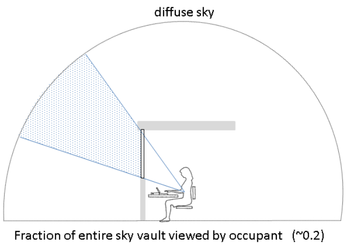
Figure C-1 Fraction of sky vault in occupant’s view ( fsvv ).
Table C-1 Symbols and Units
Symbol Description Unit
ERF Effective radiant field W/m [2]
feff Fraction of body surface exchanging radiation with surroundings hr Radiation heat transfer coefficient W/m [2] ·K
ta Air temperature °C
LW Average long-wave radiation absorptivity of body (0.95) SW Average short-wave radiation absorptivity of body ERF solar Effective radiant field solar component W/m [2]
Esolar Total short-wave solar radiant flux W/m [2]
Edir Direct-beam component of short-wave solar radiant flux W/m [2]
Ediff Diffuse component of short-wave solar radiant flux W/m [2]
Erefl Reflected component of short-wave solar radiant flux W/m [2]
fsvv Fraction of sky vault exposed to body Tsol Window system glazing unit plus shade solar transmittance Idir Direct solar beam intensity W/m [2]
Idiff Diffuse solar intensity W/m [2]
ITH Total horizontal solar intensity W/m [2]
fp Projected area factor fbes Fraction of body surface exposed to sun Solar altitude angle deg
SHARP Solar horizontal angle relative to front of person deg
Rfloor Floor reflectance (fixed at 0.6)
Posture (seated, standing, or horizontal)
30 ANSI/ASHRAE Standard 55-2023
PDF Page 33
fbes = 1 fbes = 0.5 fbes = 0.3
Figure C-2 Fraction of body exposed to sun fbes , not including the body’s self shading. It is acceptable to simplify fbes to equal the fraction of the distance between head and toe exposed to direct sun, as shown. ( Informative Note: 1.0 is the greatest possible value for fbes, because the body’s self shading is not included in fbes .)
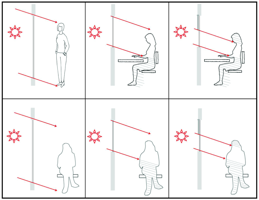
Range of Inputs
Min to Max
horizontal
| t Variables and Ranges for Calculation Procedure | Col2 | Col3 |
|---|---|---|
| Description | Unit | Allowable Default Value |
| Short-wave radiation absorptivity | — | 0.7 |
| Fraction of sky vault exposed to body | — | N/A |
| Window system glazing unit plus shade solar transmittance | — | N/A |
| Direct solar beam intensity | W/m2 | 900 |
| Fraction of the possible body surface exposed to sun | — | N/A |
| Solar altitude angle | deg | N/A |
| Solar horizontal angle relative to person | deg | N/A |
| Posture (seated, standing, or horizontal) | N/A |
ANSI/ASHRAE Standard 55-2023 31
PDF Page 34
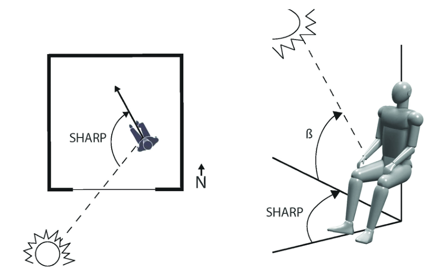
Figure C-3 Solar horizontal angle relative to the front of the person (SHARP) and solar altitude .
Table C-3 Sky Vault View Fraction fsvv for Single-Sided Window Geometry and Occupant Location
| Window Width, ft (m) | 30 (9.1) | 150 (45.5) | 30 (9.1) | 150 (45.5) | 30 (9.1) | 150 (45.5) | 30 (9.1) | 150 (45.5) | 6 (1.8) | 6 (1.8) | 6 (1.8) | 4 (1.2) | 4 (1.2) |
|---|---|---|---|---|---|---|---|---|---|---|---|---|---|
| Window Height, ft (m) | 10 (3) | 10 (3) | 6 (1.8) | 6 (1.8) | 10 (3) | 10 (3) | 6 (1.8) | 6 (1.8) | 9 (2.7) | 6 (1.8) | 6 (1.8) | 4 (1.2) | 4 (1.2) |
| Distance from Window to Occupant, ft (m) | 3.3 (1) | 3.3 (1) | 3.3 (1) | 3.3 (1) | 6 (1.8) | 6 (1.8) | 6 (1.8) | 6 (1.8) | 3.3 (1) | 3.3 (1) | 6 (1.8) | 3.3 (1) | 6 (1.8) |
| Fsvv | 27% | 31% | 20% | 23% | 17% | 21% | 11% | 14% | 14% | 11% | 4% | 6% | 2% |
Table C-4 Direct-Beam Solar Radiation Values for a Standard Cloudless Atmosphere, by Solar Altitude
| 5 | 10 | 20 | 30 | 40 | 50 | 60 | 70 | 80 |
|---|---|---|---|---|---|---|---|---|
| 210 | 390 | 620 | 740 | 810 | 860 | 890 | 910 | 920 |
C3. COMPUTER PROGRAM FOR CALCULATING COMFORT IMPACT OF SOLAR GAIN ON OCCUPANTS
The following code is one implementation of the solar calculation using JavaScript in SI units.
function find_span(arr, x){
/* For ordered array arr and value x, find the left index of the
closed interval that the value falls in. */
for (var i = 0; i < arr.length - 1; i++){
if (x <= arr[i+1] && x >= arr[i]){ return i; } } return -1; }
32 ANSI/ASHRAE Standard 55-2023
PDF Page 35
function radians_to_degrees(radians) {
const pi = Math.PI; return radians * (180 / pi); }
function degrees_to_radians(degrees) { const pi = Math.PI; return degrees * (pi / 180); }
function get_fp(alt, sharp, posture){ /* This function calculates the projected sunlit fraction (fp) given
a seated or standing posture, a solar altitude, and a solar horizontal angle relative to the person (SHARP). fp values are taken from Thermal Comfort, Fanger 1970, Danish Technical Press.
alt : altitude of sun in degrees [0, 90] (beta) Integer sharp : sun’s horizontal angle relative to person in degrees [0, 180] Integer */
if (posture == “horizontal”) { //transpose alt and sharp for a horizontal person
const altitude_new = radians_to_degrees(
Math.asin(
Math.sin(degrees_to_radians(Math.abs(sharp - 90))) * Math.cos(degrees_to_radians(alt)) ) ); sharp = radians_to_degrees(
Math.atan(
Math.sin(degrees_to_radians(sharp)) * Math.tan(degrees_to_radians(90 - alt)) ) );
alt = altitude_new; }
var fp; var alt_range = [0, 15, 30, 45, 60, 75, 90]; var sharp_range = [0, 15, 30, 45, 60, 75, 90, 105, 120, 135, 150, 165,
180]; var alt_i = find_span(alt_range, alt); var sharp_i = find_span(sharp_range, sharp);
if (posture 'standing'|| posture ‘horizontal’){
var fp_table = [[0.35,0.35,0.314,0.258,0.206,0.144,0.082],
[0.342,0.342,0.31,0.252,0.2,0.14,0.082],
[0.33,0.33,0.3,0.244,0.19,0.132,0.082],
[0.31,0.31,0.275,0.228,0.175,0.124,0.082],
[0.283,0.283,0.251,0.208,0.16,0.114,0.082],
[0.252,0.252,0.228,0.188,0.15,0.108,0.082],
[0.23,0.23,0.214,0.18,0.148,0.108,0.082],
[0.242,0.242,0.222,0.18,0.153,0.112,0.082],
[0.274,0.274,0.245,0.203,0.165,0.116,0.082],
[0.304,0.304,0.27,0.22,0.174,0.121,0.082],
[0.328,0.328,0.29,0.234,0.183,0.125,0.082],
[0.344,0.344,0.304,0.244,0.19,0.128,0.082],
[0.347,0.347,0.308,0.246,0.191,0.128,0.082]]; } else if (posture == ‘seated’){
var fp_table = [[0.29,0.324,0.305,0.303,0.262,0.224,0.177],
[0.292,0.328,0.294,0.288,0.268,0.227,0.177],
ANSI/ASHRAE Standard 55-2023 33
PDF Page 36
[0.288,0.332,0.298,0.29,0.264,0.222,0.177],
[0.274,0.326,0.294,0.289,0.252,0.214,0.177],
[0.254,0.308,0.28,0.276,0.241,0.202,0.177],
[0.23,0.282,0.262,0.26,0.233,0.193,0.177],
[0.216,0.26,0.248,0.244,0.22,0.186,0.177],
[0.234,0.258,0.236,0.227,0.208,0.18,0.177],
[0.262,0.26,0.224,0.208,0.196,0.176,0.177],
[0.28,0.26,0.21,0.192,0.184,0.17,0.177],
[0.298,0.256,0.194,0.174,0.168,0.168,0.177],
[0.306,0.25,0.18,0.156,0.156,0.166,0.177],
[0.3,0.24,0.168,0.152,0.152,0.164,0.177]]; } var fp11 = fp_table[sharp_i][alt_i]; var fp12 = fp_table[sharp_i][alt_i+1]; var fp21 = fp_table[sharp_i+1][alt_i]; var fp22 = fp_table[sharp_i+1][alt_i+1]; var sharp1 = sharp_range[sharp_i]; var sharp2 = sharp_range[sharp_i+1]; var alt1 = alt_range[alt_i]; var alt2 = alt_range[alt_i+1];
//Bilinear interpolation fp = fp11 * (sharp2 - sharp) * (alt2 - alt); fp += fp21 * (sharp - sharp1) * (alt2 - alt); fp += fp12 * (sharp2 - sharp) * (alt - alt1); fp += fp22 * (sharp - sharp1) * (alt - alt1); fp /= (sharp2 - sharp1) * (alt2 - alt1); return fp; }
function ERF(alt, sharp, posture, Idir, tsol, fsvv, fbes, asa){
/* ERF function to estimate the impact of solar radiation on occupant
comfort
INPUTS:
alt: altitude of sun in degrees [0, 90] sharp: sun’s horizontal angle relative to person in degrees [0,
180] posture: posture of occupant (‘seated’, ‘standing’, or ‘horizon
tal’) Idir: direct beam intensity (normal) tsol: total solar transmittance (SC * 0.87) fsvv: sky vault view fraction: fraction of sky vault in occupant’s
view [0, 1] fbes: fraction body exposed to sun [0, 1] asa: average shortwave absorptivity of body [0, 1] (alpha_sw) */ var DEG_TO_RAD = 0.0174532925; var hr = 6; var Idiff = 0.2 * Idir; var fp = get_fp(alt, sharp, posture);
if (posture'standing' || posture ‘horizontal’){
var feff = 0.725; } else if (posture==‘seated’){
var feff = 0.696; } else {
console.log(“Invalid posture (choose seated or seated)”); return; }
var sw_abs = asa; var lw_abs = 0.95;
34 ANSI/ASHRAE Standard 55-2023
PDF Page 37
var E_diff = 0.5 * feff * fsvv * tsol * Idiff;
var E_direct = fp * feff * fbes * tsol * Idir;
var E_refl = 0.5 * feff * fsvv * tsol * (Idir * Math.sin(alt *
DEG_TO_RAD) + Idiff) * 0.6;
var E_solar = E_diff + E_direct + E_refl;
var ERF = E_solar * (sw_abs / lw_abs);
var trsw = ERF / (hr * feff);
return {“ERF”: ERF, “trsw”: trsw};
}
C4. COMPUTER CODE VALIDATION TABLE
Table C4-1 Computer Code Validation Table
| alt | sharp | posture | Idir | tsol | fsvv | fbes | asa | ERF | trsw |
|---|---|---|---|---|---|---|---|---|---|
| 0 | 120 | Seated | 800 | 0.5 | 0.5 | 0.5 | 0.7 | 43.3 | 10.4 |
| 60 | 120 | Seated | 800 | 0.5 | 0.5 | 0.5 | 0.7 | 63.2 | 15.1 |
| 90 | 120 | Seated | 800 | 0.5 | 0.5 | 0.5 | 0.7 | 65.3 | 15.6 |
| 30 | 0 | Seated | 800 | 0.5 | 0.5 | 0.5 | 0.7 | 63.1 | 15.1 |
| 30 | 30 | Seated | 800 | 0.5 | 0.5 | 0.5 | 0.7 | 62.4 | 14.9 |
| 30 | 60 | Seated | 800 | 0.5 | 0.5 | 0.5 | 0.7 | 60.5 | 14.5 |
| 30 | 90 | Seated | 800 | 0.5 | 0.5 | 0.5 | 0.7 | 57.2 | 13.7 |
| 30 | 150 | Seated | 800 | 0.5 | 0.5 | 0.5 | 0.7 | 51.7 | 12.4 |
| 30 | 180 | Seated | 800 | 0.5 | 0.5 | 0.5 | 0.7 | 49.0 | 11.7 |
| 30 | 120 | Standing | 800 | 0.5 | 0.5 | 0.5 | 0.7 | 59.3 | 13.6 |
| 30 | 120 | Seated | 400 | 0.5 | 0.5 | 0.5 | 0.7 | 27.4 | 6.6 |
| 30 | 120 | Seated | 600 | 0.5 | 0.5 | 0.5 | 0.7 | 41.1 | 9.8 |
| 30 | 120 | Seated | 1000 | 0.5 | 0.5 | 0.5 | 0.7 | 68.5 | 16.4 |
| 30 | 120 | Seated | 800 | 0.1 | 0.5 | 0.5 | 0.7 | 11.0 | 2.6 |
| 30 | 120 | Seated | 800 | 0.3 | 0.5 | 0.5 | 0.7 | 32.9 | 7.9 |
| 30 | 120 | Seated | 800 | 0.7 | 0.5 | 0.5 | 0.7 | 76.7 | 18.4 |
| 30 | 120 | Seated | 800 | 0.5 | 0.1 | 0.5 | 0.7 | 29.3 | 7.0 |
| 30 | 120 | Seated | 800 | 0.5 | 0.3 | 0.5 | 0.7 | 42.1 | 10.1 |
| 30 | 120 | Seated | 800 | 0.5 | 0.7 | 0.5 | 0.7 | 67.5 | 16.2 |
| 30 | 120 | Seated | 800 | 0.5 | 0.5 | 0.1 | 0.7 | 36.4 | 8.7 |
| 30 | 120 | Seated | 800 | 0.5 | 0.5 | 0.3 | 0.7 | 45.6 | 10.9 |
| 30 | 120 | Seated | 800 | 0.5 | 0.5 | 0.7 | 0.7 | 64.0 | 15.3 |
| 30 | 120 | Seated | 800 | 0.5 | 0.5 | 0.5 | 0.3 | 23.5 | 5.6 |
| 30 | 120 | Seated | 800 | 0.5 | 0.5 | 0.5 | 0.5 | 39.1 | 9.4 |
| 30 | 120 | Seated | 800 | 0.5 | 0.5 | 0.5 | 0.9 | 70.4 | 16.9 |
| 30 | 120 | Seated | 800 | 0.5 | 0.5 | 0.5 | 0.7 | 54.8 | 13.1 |
| 45 | 0 | Horizontal | 700 | 0.8 | 0.2 | 0.5 | 0.7 | 60.9 | 14.0 |
| 45 | 45 | Horizontal | 700 | 0.8 | 0.2 | 0.5 | 0.7 | 65.8 | 15.1 |
| 45 | 45 | Horizontal | 800 | 0.5 | 0.5 | 0.5 | 0.7 | 70.9 | 16.3 |
ANSI/ASHRAE Standard 55-2023 35
PDF Page 38
(This is a normative appendix and is part of this standard.)
NORMATIVE APPENDIX D PROCEDURE FOR EVALUATING COOLING EFFECT OF ELEVATED AIR SPEED USING STANDARD EFFECTIVE TEMPERATURE (SET)
D1. CALCULATION OVERVIEW
Section 5.3 requires that the elevated air speed adjustment be used when average air speed Va is greater than 0.10 m/s (20 fpm). This appendix describes the calculation procedures for the elevated air speed adjustment. For a given set of environmental and personal variables, including an elevated average air speed, an average air temperature ta, and a mean radiant temperature tr, the SET is first calculated. Then the average air speed Va is replaced by still air (0.1 m/s [20 fpm]), and the average air temperature and radiant temperature are adjusted according to the cooling effect (CE). The CE of the elevated air speed is the value that, when subtracted equally from both the average air temperature and the mean radiant temperature, yields the same SET under still air as in the first SET calculation under elevated air speed. The PMV adjusted for an environment with elevated average air speed is calculated using the adjusted average air temperature, the adjusted radiant temperature, and still air (0.1 m/s [20 fpm]).
a. Enter the average air temperature ta, radiant temperature, relative humidity, clo value, and met rate. b. Set the average air speed Va . c. Note the calculated value for SET in the output data. d. Reduce the average air speed Va to 0.1 m/s (20 fpm). e. Reduce the average air temperature ta and radiant temperature tr equally in small increments until the
SET is equal to the value noted in Step (c). f. The CE is the quantity by which the average air temperature and radiant temperature have been reduced. The resulting air temperature value is the adjusted average air temperature, and the resulting radiant temperature is the adjusted mean radiant temperature. g. The PMV adjusted for elevated average air speed is calculated using the following inputs:
- Adjusted average air temperature from Step (f)
- Adjusted mean radiant temperature from Step (f)
- Average air speed Va of 0.1 m/s (20 fpm)
- Original relative humidity
- Original clo value
- Original met rate
D2. CALCULATION PROCEDURE
The following is a formal description of this process that can be automated.
Suppose ta is the average air temperature and elev is the elevated average air speed, such that elev - 0.1 m/s (20 fpm). Let still = 0.1 m/s (20 fpm). Consider functions PMV and SET, which take six parameters, which we will denote with the shorthand PMV(.,) and SET(.,). The variables of importance will be listed explicitly, while the parameters that are invariant will be denoted by “*”. The variables we will refer to explicitly are the average air temperature ta, mean radiant temperature tr, average air speed Va, and relative humidity RH.
tr
To define the CE, we assert that it satisfies the following:
SET ta tr elev - = SET ta - CE tr - CE still -
(D-1)
That is, the adjusted average air temperature yields the same SET, given still air, as the actual air temperature does at elevated average air speed. In order to determine the cooling effect, an iterative root-finding method such as the bisection or secant method may be employed. The root of the parameterized function f (ce) is the CE:
f ce = SET ta tr elev - - SET ta - ce tr - ce still -
The adjusted PMV is given by
PMV adj = PMV ta - CE tr - CE still -
(D-2)
(D-3)
Informative Note: For the use of SET in ASHRAE Standard 55, the function for self-generated air speed as
a function of met rate has been removed.
D3. VALIDATION TABLE FOR SET CALCULATION
Software implementations and other methods of SET calculation shall be validated against Table D-1.
36 ANSI/ASHRAE Standard 55-2023
PDF Page 39
Table D-1 Validation Table for SET Computer Model (for a standing person)
| Temperature | MRT | Air Speed | RH | met | clo | SET |
|---|---|---|---|---|---|---|
| °C °F | °C °F | m/s fpm | % | % | % | °C °F |
| 25 77 0 32 10 50 15 59 20 68 30 86 40 104 25 77 25 77 25 77 25 77 25 77 25 77 25 77 25 77 25 77 25 77 25 77 25 77 25 77 25 77 25 77 | 25 77 25 77 25 77 25 77 25 77 25 77 25 77 25 77 25 77 25 77 25 77 25 77 25 77 10 50 40 104 25 77 25 77 25 77 25 77 25 77 25 77 25 77 | 0.15 29.5 0.15 29.5 0.15 29.5 0.15 29.5 0.15 29.5 0.15 29.5 0.15 29.5 0.15 29.5 0.15 29.5 0.1 19.7 0.6 118.1 1.1 216.5 3 590.6 0.15 29.5 0.15 29.5 0.15 29.5 0.15 29.5 0.15 29.5 0.15 29.5 0.15 29.5 0.15 29.5 0.15 29.5 | 50 50 50 50 50 50 50 10 90 50 50 50 50 50 50 50 50 50 50 50 50 50 | 1 1 1 1 1 1 1 1 1 1 1 1 1 1 1 1 1 1 1 0.8 2 4 | 0.5 0.5 0.5 0.5 0.5 0.5 0.5 0.5 0.5 0.5 0.5 0.5 0.5 0.5 0.5 0.1 1 2 4 0.5 0.5 0.5 | 23.8 74.9 12.1 53.7 16.8 62.3 19.2 66.5 21.5 70.7 26.4 79.5 34.1 93.8 23.3 73.9 24.8 76.6 24.0 75.2 21.3 70.4 20.2 68.4 18.7 65.6 15.3 59.6 31.6 88.9 20.7 69.3 27.2 81.0 32.4 90.3 37.8 99.7 23.3 73.9 25.9 78.7 30.4 86.8 |
D4. COMPUTER PROGRAM FOR CALCULATION OF SET
The following code is one implementation of the SET calculation using JavaScript in SI units. If the following code is used to calculate the cooling effect as described in Normative Appendix D, the input parameter CALCULATE_CE should be set equal to “true.” Alternatively, if it is used to calculate the SET temperature, CALCULATE_CE should be set to “false.”
FindSaturatedVaporPressureTorr = function(T) {
/* Helper function for pierceSET calculates Saturated Vapor Pres
sure(Torr)at Temperature T (°C) */
return Math.exp(18.6686 - 4030.183/(T + 235.0)); } pierceSET = function(TA, TR, VEL, RH, MET, CLO, WME, PATM,
CALCULATE_CE=false, BODY_POSITION) {
/* Input variables - TA (air temperature): °C,
TR (mean radiant temperature): °C, VEL (air speed): m/s, RH (relative humidity): %, MET: met unit CLO: clo unit WME (external work): W/m [2], PATM (atmospheric pressure): kPa BODY_POSITION (body position): “sitting or standing”*/
ANSI/ASHRAE Standard 55-2023 37
PDF Page 40
var KCLO = 0.25; var BODYWEIGHT = 69.9; //kg var BODYSURFACEAREA = 1.8258; //m [2] var METFACTOR = 58.2; //W/m [2] var SBC = 0.000000056697; //Stefan-Boltzmann constant (W/m [2] K4) var CSW = 170.0; var CDIL = 200; var CSTR = 0.5; var LTIME = 60.0; var VaporPressure = RH * FindSaturatedVaporPressureTorr(TA)/100.0; var AirSpeed = Math.max(VEL, 0.1); var TempSkinNeutral = 33.7; var TempCoreNeutral = 36.8; var TempBodyNeutral = 36.49; var SkinBloodFlowNeutral = 6.3; var TempSkin = TempSkinNeutral; //Initial values var TempCore = TempCoreNeutral; var SkinBloodFlow = SkinBloodFlowNeutral; var MSHIV = 0.0; var ALFA = 0.1; var ESK = 0.1 * MET; var PressureInAtmospheres = PATM * 0.009869; var RCL = 0.155 * CLO; var FACL = 1.0 + 0.15 * CLO; var LR = 2.2/PressureInAtmospheres; /* Lewis Relation is 2.2 at sea
level */ var RM = MET * METFACTOR; var M = MET * METFACTOR;
if (CLO <= 0) {
var WCRIT = 0.38 * Math.pow(AirSpeed, -0.29); var ICL = 1.0; } else {
var WCRIT = 0.59 * Math.pow(AirSpeed, -0.08); var ICL = 0.45; } let heatTransferConvMet; if (MET < 0.85) {
heatTransferConvMet = 3.0; } else {
heatTransferConvMet = 5.66 * Math.pow(MET - 0.85, 0.39); } let CHC = 3.0 * Math.pow(PressureInAtmospheres, 0.53); let CHCV = 8.600001 * Math.pow(AirSpeed * PressureInAtmospheres,
0.53); CHC = Math.max(CHC, CHCV); if (!CALCULATE_CE) {
CHC = Math.max(CHC, heatTransferConvMet); } var CHR = 4.7; var CTC = CHR + CHC; var RA = 1.0/(FACL * CTC); /* Resistance of air layer to dry heat
transfer / var TOP = (CHR * TR + CHC * TA)/CTC; var TCL = TOP + (TempSkin - TOP)/(CTC * (RA + RCL)); / TCL and CHR are solved iteratively using: H(Tsk - TOP) =
CTC(TCL - TOP), where H = 1/(RA + RCL) and RA = 1/FACL*CTC */
38 ANSI/ASHRAE Standard 55-2023
PDF Page 41
var TCL_OLD = TCL; var flag = true; var DRY, HFCS, ERES, CRES, SCR, SSK, TCSK, TCCR, DTSK, DTCR, TB, SKSIG, WARMS, COLDS, CRSIG, WARMC, COLDC, BDSIG, WARMB, COLDB, REGSW, ERSW, REA, RECL, EMAX, PRSW, PWET, EDIF, ESK;
for (var TIM = 1; TIM <= LTIME; TIM++) { //Begin iteration
do { if (flag) {
TCL_OLD = TCL; if (BODY_POSITION === “sitting”) {
// 0.7 ratio between radiation area of the body and // the body area CHR = 4.0 * 0.95 * SBC * Math.pow(((TCL + TR)/2.0 + 273.15),
3.0) *0.7; }else {// if standing
// 0.73 ratio between radiation area of the body and // the body area CHR = 4.0 * 0.95 * SBC * Math.pow(((TCL + TR)/2.0 + 273.15),
3.0) *0.73; CTC = CHR + CHC;
RA = 1.0/(FACL * CTC);/Resistance of air layer to dry heat transfer/ TOP = (CHR * TR + CHC * TA)/CTC; } TCL = (RA * TempSkin + RCL * TOP)/(RA + RCL); flag = true; } while (Math.abs(TCL - TCL_OLD) > 0.01);
flag = false; DRY = (TempSkin - TOP)/(RA + RCL); HFCS = (TempCore - TempSkin) * (5.28 + 1.163 * SkinBloodFlow); ERES = 0.0023 * M * (44.0 - VaporPressure); CRES = 0.0014 * M * (34.0 - TA); SCR = M - HFCS - ERES - CRES - WME; SSK = HFCS - DRY - ESK; TCSK = 0.97 * ALFA * BODYWEIGHT; TCCR = 0.97 * (1 - ALFA) * BODYWEIGHT; DTSK = (SSK * BODYSURFACEAREA)/(TCSK * 60.0); //°C/min DTCR = SCR * BODYSURFACEAREA/(TCCR * 60.0); //°C/min TempSkin = TempSkin + DTSK; TempCore = TempCore + DTCR; TB = ALFA * TempSkin + (1 - ALFA) * TempCore; SKSIG = TempSkin - TempSkinNeutral;
if (SKSIG > 0) {
WARMS = SKSIG; COLDS = 0.0; } else {
WARMS = 0.0; COLDS = -1.0 * SKSIG; } CRSIG = (TempCore - TempCoreNeutral);
if (CRSIG > 0) {
WARMC = CRSIG; COLDC = 0.0; }
else {
WARMC = 0.0; COLDC = -1.0 * CRSIG; }
ANSI/ASHRAE Standard 55-2023 39
PDF Page 42
BDSIG = TB - TempBodyNeutral; WARMB = (BDSIG > 0) * BDSIG; SkinBloodFlow = (SkinBloodFlowNeutral + CDIL * WARMC)/(1 + CSTR
- COLDS);
SkinBloodFlow = Math.max(0.5, Math.min(90.0, SkinBloodFlow)); REGSW = CSW * WARMB * Math.exp(WARMS/10.7); REGSW = Math.min(REGSW, 500.0); var ERSW = 0.68 * REGSW; //Evaporative resistance of air layer var REA = 1.0/(LR * FACL * CHC);
//Evaporative resistance of clothing (icl=.45) var RECL = RCL/(LR * ICL); var EMAX = (FindSaturatedVaporPressureTorr(TempSkin) VaporPressure)/(REA + RECL); var PRSW = ERSW/EMAX; var PWET = 0.06 + 0.94 * PRSW; var EDIF = PWET * EMAX - ERSW; var ESK = ERSW + EDIF; if (PWET > WCRIT) {
PWET = WCRIT; PRSW = WCRIT/0.94; ERSW = PRSW * EMAX; EDIF = 0.06 * (1.0 - PRSW) * EMAX; ESK = ERSW + EDIF;
} if (EMAX < 0) { EDIF = 0; ERSW = 0; PWET = WCRIT; PRSW = WCRIT; ESK = EMAX;
} ESK = ERSW + EDIF; MSHIV = 19.4 * COLDS * COLDC; M = RM + MSHIV; ALFA = 0.0417737 + 0.7451833/(SkinBloodFlow + 0.585417); } //End iteration
var HSK = DRY + ESK; //Total heat loss from skin var RN = M - WME; //Net metabolic heat production var ECOMF = 0.42 * (RN - (1 * METFACTOR)); if (ECOMF < 0.0) ECOMF = 0.0; //From Fanger EMAX = EMAX * WCRIT; var W = PWET; var PSSK = FindSaturatedVaporPressureTorr(TempSkin); var CHRS = CHR; //Definition of ASHRAE std. environment, denoted “S” CHCS = 3.0 * Math.pow(PressureInAtmospheres, 0.53);
if (!CALCULATE_CE && MET > 0.85) {
CHCS = Math.max(CHCS, heatTransferConvMet); }
if (CHCS < 3.0) CHCS = 3.0; var CTCS = CHCS + CHRS; var RCLOS = 1.52/((MET - WME/METFACTOR) + 0.6944) - 0.1835; var RCLS = 0.155 * RCLOS; var FACLS = 1.0 + KCLO * RCLOS; var FCLS = 1.0/(1.0 + 0.155 * FACLS * CTCS * RCLOS); var IMS = 0.45;
40 ANSI/ASHRAE Standard 55-2023
PDF Page 43
var ICLS = IMS * CHCS/CTCS * (1 - FCLS)/(CHCS/CTCS - FCLS * IMS); var RAS = 1.0/(FACLS * CTCS); var REAS = 1.0/(LR * FACLS * CHCS); var RECLS = RCLS/(LR * ICLS); var HD_S = 1.0/(RAS + RCLS); var HE_S = 1.0/(REAS + RECLS);
//SET determined using Newton’s iterative solution
var DELTA = .0001; var dx = 100.0; var SET, ERR1, ERR2; var SET_OLD = TempSkin - HSK/HD_S; //Lower bound for SET while (Math.abs(dx) > .01) { ERR1 = (HSK - HD_S * (TempSkin - SET_OLD) - W * HE_S *
(PSSK - 0.5 * FindSaturatedVaporPressureTorr(SET_OLD))); ERR2 = (HSK - HD_S * (TempSkin - (SET_OLD + DELTA)) - W * HE_S *
PSSK - 0.5 * FindSaturatedVaporPressureTorr((SET_OLD + DELTA))); SET = SET_OLD - DELTA * ERR1/(ERR2 - ERR1); dx = SET - SET_OLD; SET_OLD = SET; } return SET; }
ANSI/ASHRAE Standard 55-2023 41
PDF Page 44
(This appendix is not part of this standard. It is merely informative and does not contain requirements necessary for conformance to the standard. It has not been processed according to the ANSI require- ments for a standard and may contain material that has not been subject to public review or a consen- sus process. Unresolved objectors on informative material are not offered the right to appeal at ASHRAE or ANSI.)
INFORMATIVE APPENDIX E CONDITIONS THAT PROVIDE THERMAL COMFORT
E1. INTRODUCTION
Thermal comfort is that condition of mind that expresses satisfaction with the thermal environment. Because there are large variations, physiologically and psychologically, from person to person, it is difficult to satisfy everyone in a space. The environmental conditions required for comfort are not the same for everyone. Extensive laboratory and field data have been collected that provide the necessary statistical information to define conditions that a specified percentage of occupants will find thermally comfortable.
Note that the pairs of terms “satisfaction”/“acceptability,” “satisfactory”/“acceptable,” and “are satisfied with”/“accept” are each considered synonymous in the standard, though the standard uses “satisfaction” as its standard nomenclature.
E2. THERMAL COMFORT FACTORS
Six primary factors must be addressed when defining conditions for thermal comfort. A number of other, secondary factors affect comfort in some circumstances. The six primary factors are as follows:
a. Metabolic rate b. Clothing insulation c. Air temperature d. Radiant temperature e. Air speed f. Humidity
The first two factors are characteristics of the occupants, and the remaining four factors are conditions of the thermal environment. Detailed descriptions of these factors are presented in Section 3 and Informative Appendix E through Informative Appendix G. These must be clearly understood in order to use the methods of Section 5 effectively.
E3. VARIATION AMONG OCCUPANTS
For each occupant, the activity level, represented as metabolic rate M in mets, and the clothing worn by the occupants, represented as insulation Icl in clo, must be considered in applying this standard. When there are substantial differences in physical activity and/or clothing for occupants of a space, these differences must be considered.
In some cases, it will not be possible to achieve a satisfactory thermal environment for all occupants of a space due to individual differences, including activity and/or clothing. If the requirements are not met for some known set of occupants, then the standard requires that these occupants be identified.
E4. TEMPORAL VARIATION
It is possible for all six primary factors to vary with time. This standard only addresses thermal comfort in a steady state (with some limited specifications for temperature variations with time in Section 5.3.6).
As a result, people entering a space that meets the requirements of this standard may not immediately find the conditions comfortable if they have experienced different environmental conditions just prior to entering the space. The effect of prior exposure or activity may affect comfort perceptions for approximately one hour.
E5. LOCAL THERMAL DISCOMFORT
Nonuniformity is addressed in Section 5.3.5. Factors 1 through 6 may be nonuniform over an occupant’s body, and this nonuniformity may be an important consideration in determining thermal comfort.
E6. VARIATION IN ACTIVITY LEVEL
The vast majority of the available thermal comfort data pertain to sedentary or near-sedentary physical activity levels typical of office work. This standard is intended primarily for these conditions. However, it is acceptable to use the standard to determine appropriate environmental conditions for moderately elevated activity. It does not apply to sleeping or bed rest. The body of available data does not contain significant
42 ANSI/ASHRAE Standard 55-2023
PDF Page 45
information regarding the comfort requirements of children, the disabled, or the infirm. It is acceptable to apply the information in this standard to these types of occupants if it is applied judiciously to groups of occupants, such as those found in classroom situations.
E7. NATURALLY CONDITIONED SPACES
Section 5.3 contains the methodology that should be used for most applications. The conditions required for thermal comfort in spaces that are naturally conditioned are not necessarily the same as those conditions required for other indoor spaces. Field experiments have shown that in naturally conditioned spaces where occupants have control of operable windows, the subjective notion of comfort is different because of different thermal experiences, availability of control, and resulting shifts in occupant expectations. Section 5.4 specifies criteria required for a space to be considered naturally conditioned. The methods of Section 5.4 may, as an option, be applied to spaces that meet these criteria. The methods of Section 5.4 may not be applied to other spaces.
E8. SPACE DESIGN FOR OCCUPANTS IN THERMAL TRANSITION
E8.1 Problem. People arriving in buildings have different activity levels, body temperatures, and skin wetness from those who have been indoors longer, and they may experience discomfort during the transition. These transitions occur in outdoor-to-indoor transitional spaces, such as lobbies, retail stores, and transit centers, but they also continue in interior destination spaces such as offices, conference rooms, classrooms, and restaurants. It is challenging to condition such spaces to suit the comfort requirements of all the occupants, some of whom may not be experiencing the transition. There are energy and economic consequences to the methods employed.
On the positive side, there are possible comfort benefits to the occupant from experiencing a transition from a cold or hot environment toward a neutral one. A favorable body or skin temperature gradient is perceived as pleasant at a significantly higher intensity than is experienced in steady-state comfort; this is termed alliesthesia . It affects both temperature gradients occurring over time and among different parts of the body. These temperature gradients may involve thermal stimuli from the environment that are above what is allowed in the standard for steady-state conditions.
Winter situation: In cold seasons, the body heat deficits from outdoor exposure (exposed body surfaces and extremities might be cold upon entering the building) can take a long time to warm up. They can be targeted and corrected by hot air curtains, focused or local radiant heaters, and by direct thermal contact with warmed surfaces in active seats and desk furniture. There is at this point insufficient information about transient comfort in warming transitions to suggest specific design solutions for winter.
Summer situation: In hot conditions, people
a. Enter buildings with elevated body temperature acquired in the outdoor environment and from the meta bolic exertion of walking b. Change from walking to sitting activity, during which their metabolic rate decreases
When people enter buildings, the elevated body heat from outdoor exposure and walking has to be removed from the skin before it can cause discomfort indoors. Unfortunately, the outdoor wind levels and the self-generated wind from walking disappear when one enters a building and becomes stationary. This causes a spike in a person’s skin temperature and sweat rate as the body compensates for the lost convective cooling. The resulting discomfort can persist for over an hour. During this period the occupant may feel the need to complain or to reset the room thermostat to a cooler set point. The resulting cooler space temperature then persists well beyond the occupant’s period of thermal transition, and may overcool multiple occupants while increasing the building’s cooling energy.
In addition, there are spaces in which some occupants are continuously at higher metabolic rates than others and require different levels of cooling. An example might be diners and waiters at restaurants, or clerks and shoppers in stores. Their variation in cooling requirements takes place across short distances or (from the perspective of a moving occupant) short time steps.
The environmental control options for removing body heat differ greatly in their effectiveness. Current research shows that elevating indoor air movement is far more effective than reducing indoor temperature, both for maintaining comfort throughout transitions from outdoors to indoors, and during the metabolic downstep when a person sits down. When the indoor operative temperature alone is used to remove body heat, both subjective comfort votes and physiological responses respond much more slowly.
This finding about occupant cooling has important practical implications for the design and operation of buildings, one related to comfort and one to energy efficiency:
ANSI/ASHRAE Standard 55-2023 43
PDF Page 46
a. Comfort: conditioning with cooled air inherently covers large areas that may have multiple occupants,
some of whom are not experiencing the thermal transient and do not need the cooling. Air movement, in contrast, can be directed into smaller areas that do not overcool longer-term sedentary residents of the space. b. Energy: transition spaces at the indoor/outdoor boundary (stores, lobbies, transit stations) inevitably leak
their cooled air to the outdoors, and the colder that these spaces are maintained, the greater the energy loss. c. Cooling occupants by air movement provides equivalent comfort at warmer interior temperatures, so less
energy is lost from leaked air. Also, air movement cooling is inherently less energy intensive than the equivalent cooling from lowering a space’s air temperature or humidity level.
It is possible to quantify the combinations of air movement and air temperature that are most effective at keeping people comfortable during the time they are in lobbies, stores, and other transition spaces. One can also quantify the combinations needed by newly arrived occupants once they arrive in long-term sedentary spaces, such as their workstations, conference rooms, classrooms, waiting rooms, and restaurants. E8.2 Design Approach for Cooling Transition. Translating these environmental conditions into design, transition zones should be able to provide sufficient elevated air movement within the space that an occupant’s travel through it is comfortable throughout. The indoor destination (for example, an office workplace) should have personally controlled air movement sources available to deal with the transition to sedentary in spaces whose temperatures are not under the control of the occupant. The operational goal should be to avoid overcooling the space temperature, and to maintain it at an appropriately warm level (not below 25°C
[77°F]) to allow the most effective draft-free convective cooling. Here are example strategies based on current research results:
a. Transition zones: Maintain indoor operative temperature between 26°C to 28°C (78.8 to 82.4 °F) (for
humidities around 50% rh) with a continuous ambient air speed of 0.6 to 0.8 m/s (118 to 157 fpm) in the parts of the space occupied by people in transition. The most common source of room-wide air speed is ceiling fans, though large horizontally oriented fans are also used. b. Destination workstations: Make available a personally controlled fan capable of 1.2 m/s (236 fpm) on
the upper body while maintaining an operative temperature between 25°C to 28°C (77°F to 82.4°F) and ambient air speed of at least 0.3 m/s (59 fpm).
For sedentary long-term occupants in the transition zone, (sales clerks, receptionists, etc.), provide the ability to reduce air speed in their locations.
44 ANSI/ASHRAE Standard 55-2023
PDF Page 47
(This appendix is not part of this standard. It is merely informative and does not contain requirements necessary for conformance to the standard. It has not been processed according to the ANSI require- ments for a standard and may contain material that has not been subject to public review or a consen- sus process. Unresolved objectors on informative material are not offered the right to appeal at ASHRAE or ANSI.)
INFORMATIVE APPENDIX F USE OF METABOLIC RATE DATA
The data presented in Table 5-1 are reproduced from ASHRAE Handbook—Fundamentals [ 1], Chapter 9. The values in the table represent typical metabolic rates per unit of skin surface area for an average adult (DuBois area = 1.8 m [2] [19.6 ft [2] ]) for activities performed continuously. This Handbook chapter provides additional information for estimating and measuring activity levels. General guidelines for the use of these data follow.
Not every activity that may be of interest is included in this table. Users of this standard should use their judgment to match the activities being considered to comparable activities in the table. Some of the data in this table are reported as a range and some as a single value. The format for a given entry is based on the original data source and is not an indication of when a range of values should or should not be used. For all activities except sedentary activities, the metabolic rate for a given activity is likely to have a substantial range of variation that depends on the individual performing the task and the circumstances under which the task is performed.
It is permissible to use a time-weighted average metabolic rate for individuals with activities that vary over a period of one hour or less. For example, a person who typically spends 30 minutes out of each hour “lifting/packing,” 15 minutes “filing, standing,” and 15 minutes “walking about” has an average metabolic rate of 0.50 × 2.1 + 0.25 × 1.4 + 0.25 × 1.7 = 1.8 met. Such averaging should not be applied when the period of variation is greater than one hour. For example, a person who is engaged in “lifting/packing” for more than one hour and then “filing, standing” for more than one hour should be treated as having two distinct metabolic rates.
As metabolic rates increase above 1.0 met, the evaporation of sweat becomes an increasingly important factor for thermal comfort. The PMV method does not fully account for this factor, and this standard should not be applied to situations where the time-averaged metabolic rate is above 4.0 met.
Rest breaks (scheduled or hidden) or other operational factors (get parts, move products, etc.) combine to limit time-weighted metabolic rates to about 2.0 met in most applications.
Time averaging of metabolic rates only applies to an individual. The metabolic rates associated with the activities of various individuals in a space may not be averaged to find a single, average metabolic rate to be applied to that space. The range of activities of different individuals in the space, and the environmental conditions required for those activities, should be considered in applying this standard. For example, the customers in a restaurant may have a metabolic rate near 1.0 met, while the servers may have a metabolic rate closer to 2.0 met. Each of these groups of occupants should be considered separately in determining the conditions required for comfort. In some situations, it will not be possible to provide an acceptable level or the same level of comfort to all disparate groups of occupants (e.g., restaurant customers and servers).
The metabolic rates in Table 5-1 were determined when the subjects’ thermal sensation was close to neutral. It is not yet known the extent to which people may modify their metabolic rate to decrease warm discomfort.
ANSI/ASHRAE Standard 55-2023 45
PDF Page 48
(This appendix is not part of this standard. It is merely informative and does not contain requirements necessary for conformance to the standard. It has not been processed according to the ANSI require- ments for a standard and may contain material that has not been subject to public review or a consen- sus process. Unresolved objectors on informative material are not offered the right to appeal at ASHRAE or ANSI.)
INFORMATIVE APPENDIX G CLOTHING INSULATION
The amount of thermal insulation worn by a person has a substantial impact on thermal comfort and is an important variable in applying this standard. Clothing insulation is expressed in a number of ways. In this standard, the clothing insulation Icl of an ensemble expressed as a clo value is used. Users not familiar with clothing insulation terminology should refer to ASHRAE Handbook—Fundamentals [ 1], Chapter 9, for more information.
The insulation provided by clothing can be determined by a variety of means, and if accurate data are available from other sources, such as measurement with thermal manikins, these data are acceptable for use. When such information is not available, the tables in this standard may be used to estimate clothing insulation Icl using one of the methods described below. Regardless of the source of the clothing insulation value, this standard is not intended for use with clothing ensembles with more than 1.5 clo of insulation, nor is it intended for use when occupants wear clothing that is highly impermeable to moisture transport (e.g., chemical protective clothing or rain gear).
Four methods for estimating clothing insulation Icl are presented. Methods 1, 2, and 3 are listed in order of accuracy. The tables used in the standard are derived from ASHRAE Handbook—Fundamentals [1], Chapter 9.
- **Method 1:** Table 5-2 of this standard lists the insulation provided by a variety of common clothing
ensembles. If the ensemble in question matches reasonably well with one of the ensembles in this table, then the indicated value of Icl should be used.
- **Method 2:** Table 5-3 of this standard presents the thermal insulation of a variety of individual garments. It
is acceptable to add or subtract these garments from the ensembles in Table 5-2 to estimate the insulation of ensembles that differ in garment composition from those in Table 5-2. For example, if long underwear bottoms are added to Ensemble 5 in Table 5-2, the insulation of the resulting ensemble is estimated as
Icl = 1.01 + 0.15 = 1.16 clo
- **Method 3:** It is acceptable to define a complete clothing ensemble using a combination of the garments
listed in Table 5-3 of this standard. The insulation of the ensemble is estimated as the sum of the individual values listed in Table 5-3. For example, the estimated insulation of an ensemble consisting of overalls worn with a flannel shirt, t-shirt, briefs, boots, and calf-length socks is
Icl = 0.30 + 0.34 + 0.08 + 0.04 + 0.10 + 0.03 = 0.89 clo
- **Method 4:** It is acceptable to determine the clothing insulation _Icl_ with Figure 5-1 in mechanically conditioned buildings. When people select their clothing as a function of outdoor and indoor climate variables,
the most influential variable is outdoor air temperature. Figure 5-1 can be used to calculate the clothing insulation for each day of the year or for representative days. The curve in Figure 5-1 is an approximation for typical (or average) clothing. The model is based on field study and may not be appropriate for all cultures and occupancy types. The model represented in Figure 5-1 is suited to be implemented in building performance simulation software or building control systems. The model graphed in Figure 5-1 is described by the following equations:
For ta(out,6) < –5°C Icl = 1.00
For –5°C ta(out,6) < 5°C Icl = 0.818 – 0.0364 × ta(out,6)
For 5°C ta(out,6) < 26°C Icl = 10 [(–0.1635 – 0.0066 × ] [ta(out,6)] [)]
or ta(out,6) 26°C Icl = 0.46
For ta(out,6) < 23°F Icl = 1.00
For 23°F ta(out,6) < 41°F Icl = 1.465 – 0.0202 × ta(out,6)
For 41°F ta(out,6) < 78.8°F Icl = 10 [(–0.0460 – 0.00367 × ] [ta(out,6)] [)]
or ta(out,6) 78.8°F Icl = 0.46
46 ANSI/ASHRAE Standard 55-2023
PDF Page 49
Tables 5-2 and 5-3 are for a standing person. A sitting posture results in a decreased thermal insulation due to compression of air layers in the clothing. This decrease can be offset by insulation provided by the chair. Table 5-4 shows the net effect on clothing insulation Icl for typical indoor clothing ensembles that result from sitting in a chair. These data may be used to adjust clothing insulation calculated using any of the above methods. For example, the clothing insulation for a person wearing Ensemble 3 from Table 5-2 and sitting in an executive chair is 0.96 + 0.15 = 1.11 clo. For many chairs, the net effect of sitting is a minimal change in clothing insulation. For this reason, no adjustment to clothing insulation is needed if there is uncertainty as to the type of chair and/or if the activity for an individual includes both sitting and standing.
Tables 5-2 and 5-3 are for a person that is not moving. Body motion decreases the insulation of a clothing ensemble by pumping air through clothing openings and/or causing air motion within the clothing. This effect varies considerably, depending on the nature of the motion (e.g., walking versus lifting) and the nature of the clothing (stretchable and snug fitting versus stiff and loose fitting). Because of this variability, accurate estimates of clothing insulation Icl for an active person are not available unless measurements are made for the specific clothing under the conditions in question (e.g., with a walking manikin). An approximation of the clothing insulation for an active person is
Icl, active = Icl × (0.6 + 0.4/ M ) for M 1.2
where M is the metabolic rate in met units and Icl is the insulation without activity. For metabolic rates less than or equal to 1.2 met, no adjustment for motion is required. This clothing adjustment for an active person is applied automatically as part of the PMV code as described in Normative Appendix B.
When a person is sleeping or resting in a reclining posture, the bed and bedding provide considerable thermal insulation. It is not possible to determine the thermal insulation for most sleeping or resting situations unless the individual is immobile. Individuals adjust bedding to suit individual preferences. Provided adequate bedding materials are available, the thermal environmental conditions desired for sleeping and resting vary considerably from person to person and cannot be determined by the methods included in this standard.
Clothing variability among occupants in a space is an important consideration in applying this standard. This variability takes two forms. In the first form, different individuals wear different clothing due to factors unrelated to the thermal conditions. Examples include different clothing style preferences for men and women and offices where managers are expected to wear suits while other staff members may work in shirtsleeves. In the second form, the variability results from adaptation to individual differences in response to the thermal environment. For example, some individuals wear sweaters while others wear short-sleeve shirts in the same environment if there are no constraints limiting what is worn. The first form of variability results in differences in the requirements for thermal comfort between the different occupants, and these differences should be addressed in applying this standard. In this situation, it is not correct to determine the average clothing insulation Icl of various groups of occupants to determine the thermal environmental conditions needed for all occupants. Where the variability within a group of occupants is of the second form and is a result only of individuals freely making adjustments in clothing to suit their individual thermal preferences, it is correct to use a single representative average clothing insulation value for everyone in that group.
For near-sedentary activities where the metabolic rate is approximately 1.2 met, the effect of changing clothing insulation Icl on the optimum operative temperature to is approximately 6°C (11°F) per clo.
For example, Table 5-3 indicates that adding a thin, long-sleeve sweater to a clothing ensemble increases clothing insulation Icl by approximately 0.25 clo. Adding this insulation would lower the optimum operative temperature to by approximately 6°C/clo × 0.25 clo = 1.5°C (11°F/clo × 0.25 clo = 2.8°F).
ANSI/ASHRAE Standard 55-2023 47
PDF Page 50
(This appendix is not part of this standard. It is merely informative and does not contain requirements necessary for conformance to the standard. It has not been processed according to the ANSI require- ments for a standard and may contain material that has not been subject to public review or a consen- sus process. Unresolved objectors on informative material are not offered the right to appeal at ASHRAE or ANSI.)
INFORMATIVE APPENDIX H COMFORT ZONES DEFINING SATISFACTORY THERMAL CONDITIONS IN OCCUPIED SPACE
H1. INTRODUCTION
This standard generates comfort zones within the ranges of environmental and personal conditions likely to be found indoors. The boundaries of comfort zones enclose sets of conditions that are considered satisfactory by their occupancies. They are based on predicted values of how occupants on average evaluate their thermal sensation—specifically, their sense of the environment being warm or cool. Thermal sensation is individually measured by point-in-time survey questionnaires using the ASHRAE seven-point thermal sensation scale.
+3 Hot +2 Warm +1 Slightly warm 0 Neutral –1 Slightly cool –2 Cool –3 Cold
Because groups of people in a given environment exhibit considerable variance in their thermal sensation votes, the mean thermal sensation vote is needed to characterize each combination of environmental and personal conditions. In the standard, this mean vote is predicted using the predicted mean vote (PMV) model given in Normative Appendix B. The PMV model calculates the heat balance of a specified occupant and relates their thermal gains or losses to their predicted mean thermal sensation.
H2. COMFORT ZONE BOUNDARIES
The boundaries of the comfort zone are defined by equal contours of PMV values. The boundary value is set at ±0.5 PMV in thermal sensation scale units. In field studies of actual buildings, environmental conditions within comfort zones bounded by this ±0.5 value were found satisfactory by roughly 80% of occupants. This percentage varies depending on additional confounding circumstances beyond the PMV model of an occupant’s heat balance. Sources of local discomfort are thought to add to dissatisfaction, as are other factors such as occupants’ sense of personal control over their thermal environment. This effect is described in Informative Appendix L, Sections L1, L2, and L3. The measurement and evaluation methods for determining satisfaction are described in Sections 7.3.1 and 7.4.1 of the standard.
Comfort zones with the ±0.5 PMV boundaries are generated by the Thermal Comfort Tool [ 3.] They are plotted in psychrometric chart format with air temperature ta or operative temperature to on the abscissa, or in temperature vs. relative humidity format. In evaluating comfort zones, it is usually most useful to use the operative temperature parameter, as surface temperatures within indoor environments will shift along with air temperature across the width of the comfort zone.
The comfort zones are seen to shift continuously with changes to the environmental and personal input parameters that are not plotted on the two chart axes. The presence of solar radiation on the occupant is shown to shift the comfort zone toward the cool side. Elevating the air speed is shown to shift the comfort zone toward the warm side. Note that there is an additional comfort attribute to elevated air speed, that of whether occupants have control of it or not. The presence or absence of group control over air speed produces a subzoning as identified in Figure 5-4. This is also included in the output of the Thermal Comfort Tool [ 3] .
Impacts of personal factors: The outer comfort zone boundaries shift toward the left or right, depending on clo and met level. An increase of 0.1 clo or 0.1 met corresponds approximately to a 0.8°C (1.4°F) or 0.5°C (0.9°F) reduction in operative temperature to ; a decrease of 0.1 clo or 0.1 met corresponds approximately to a 0.8°C (1.4°F) or 0.5°C (0.9°F) increase in operative temperature.
The computer code in Normative Appendix B was developed for use with this standard and is incorporated into the Thermal Comfort Tool [ 3] . If any other software is used, it is the user’s responsibility to verify and document that the version used yields the same results as the code in Normative Appendix B or the Thermal Comfort Tool for the conditions for which it is applied.
48 ANSI/ASHRAE Standard 55-2023
PDF Page 51
H3. HUMIDITY LIMITS TO THE COMFORT ZONE
There are no established higher or lower humidity limits for thermal comfort; consequently, this standard does not specify a maximum or minimum humidity level. Nonthermal comfort factors, such as skin drying, irritation of mucus membranes, dryness of the eyes, and static electricity generation, may place limits on the satisfaction with very low humidity environments.
ANSI/ASHRAE Standard 55-2023 49
PDF Page 52
(This appendix is not part of this standard. It is merely informative and does not contain requirements necessary for conformance to the standard. It has not been processed according to the ANSI require- ments for a standard and may contain material that has not been subject to public review or a consen- sus process. Unresolved objectors on informative material are not offered the right to appeal at ASHRAE or ANSI.)
INFORMATIVE APPENDIX I LOCAL DISCOMFORT AND VARIATIONS WITH TIME
I1. LOCAL THERMAL DISCOMFORT
Avoiding local thermal discomfort, whether caused by a vertical air temperature difference between the feet and the head, by an asymmetric radiant field, by local convective cooling (draft), or by contact with a hot or cold floor, is essential to providing satisfactory thermal comfort.
The requirements specified in Section 5.3.5 of this standard apply directly to a lightly clothed person (with clothing insulation between 0.5 and 0.7 clo) engaged in near-sedentary physical activity (with metabolic rates between 1.0 and 1.3 met). With higher metabolic rates and/or with more clothing insulation, people are less thermally sensitive and, consequently, the risk of local discomfort is lower. Thus, it is acceptable to use the requirements of Section 5.3.5 for metabolic rates greater than 1.3 met and with clothing insulation greater than 0.7 clo, as they will be conservative. People are more sensitive to local discomfort when the whole body is cooler than neutral and less sensitive to local discomfort when the whole body is warmer than neutral. The requirements of Section 5.3.5 of this standard are based on environmental temperatures near the center of the comfort zone. These requirements apply to the entire comfort zone, but they may be conservative for conditions near the upper temperature limits of the comfort zone and may underestimate discomfort at the lower temperature limits of the comfort zone.
Table I-1 shows the expected percent dissatisfied for each source of local thermal discomfort described in Sections 5.3.5.1 through 5.3.5.4. The criteria for all sources of local thermal discomfort should be met simultaneously at the levels specified for an environment to meet the requirements of Section 5.3 of this standard. The expected percent dissatisfied for each source of local thermal discomfort described in Sections 5.3.5.1 through 5.3.5.4 should be specified.
I2. RADIANT TEMPERATURE ASYMMETRY
The thermal radiation field about the body may be nonuniform due to hot and cold surfaces and direct sunlight. This asymmetry may cause local discomfort and reduce thermal satisfaction with the space. In general, people are more sensitive to asymmetric radiation caused by a warm ceiling than that caused by hot and cold vertical surfaces. Figure I-1 gives the expected percentage of occupants dissatisfied due to radiant temperature asymmetry caused by a warm ceiling, a cool wall, a cool ceiling, or a warm wall.
The allowable radiant asymmetry limits are based on Figure I-1 and assume that a maximum of 5% of occupants are dissatisfied by radiant asymmetry.
I3. DRAFT
Draft is unwanted local cooling of the body caused by air movement. It is most prevalent when the wholebody thermal sensation is cool (below neutral). Draft sensation depends on whole-body thermal sensation, air speed, air temperature, activity, turbulence intensity, and clothing. Sensitivity to draft is greatest where the skin is not covered by clothing, especially the head region comprising the head, neck, and shoulders and the leg region comprising the ankles, feet, and legs.
Use of elevated air speed to extend the thermal comfort range is appropriate when otherwise occupants are slightly warm, as set forth in Section 5.3.4. When occupants are neutral or cooler, such as under certain combinations of met rate and clo value with operative temperatures to below 23°C (73.4°F), average air speeds within the comfort envelope of ±0.5 PMV should not exceed 0.20 m/s (40 fpm). This draft limit applies to air movement caused by the building, its fenestration, and its HVAC system and not to air movement produced by office equipment or occupants. This standard allows average air speed to exceed this draft limit if it is under the occupants’ local control and is within the elevated air-speed comfort envelope described in Section 5.3.4.
Draft at the lower-leg region may occur in buildings conditioned by thermally stratified systems, such as displacement ventilation and underfloor air distribution, or with cold-dropping airflow along external walls and/or windows. This problem could also occur in vehicles when the air is supplied at the floor level. Manufacturers of air diffusers intended for stratified systems often provide diffuser performance data that can assist designers in predicting Vankle . Various approaches are used by different manufacturers to derive the performance data. A standard method of test does not yet exist.
50 ANSI/ASHRAE Standard 55-2023
PDF Page 53
Table I-1 Expected Percent Dissatisfied Due to Sources of Local Discomfort
Vertical Air Temperature
Draft
Difference Warm or Cool Floors Radiant Asymmetry
<20% <5% <10% <5%
Figure I-1 Local thermal discomfort caused by radiant asymmetry.
Figure I-2 Air speed limits at 0.1 m (4 in.) above the floor as a function of whole-body thermal sensation and the predicted percentage of dissatisfied with ankle draft (PPD AD ).
The maximum air speed at the ankle level is deduced from the predicted percentage of dissatisfied with ankle draft PPD AD . PPD AD is an index that establishes a quantitative prediction of the percentage of thermally dissatisfied people with the draft at ankle level. PPD AD is calculated according to the following formula or is deduced from Figure I-2:
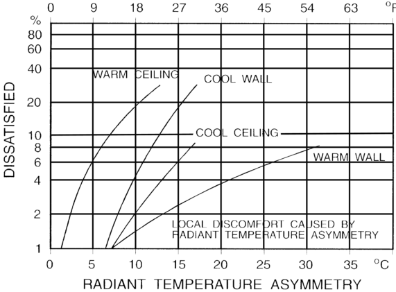
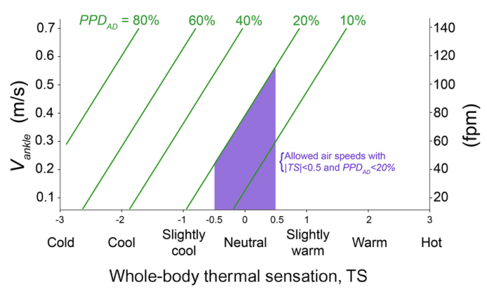
PPD AD
PPD AD
= --------------------------------------------------------------------------------------------exp - 2.58 + 3.05 Vankle - 1.06TS - 1 + exp - 2.58 + 3.05 Vankle - 1.06TS
= -----------------------------------------------------------------------------------------------exp - 2.58 + 0.015 Vankle - 1.06TS - 1 + exp - 2.58 + 0.105 Vankle - 1.06TS
, ( Vankle in m/s)
, ( Vankle in fpm)
ANSI/ASHRAE Standard 55-2023 51
PDF Page 54
where PPD AD = predicted percentage of dissatisfied with ankle draft, % TS = whole-body thermal sensation; equal to PMV calculated using the input air temperature and speed averaged over two heights: 0.6 m (24 in.) and 1.1 m (43 in.) for seated occupants and 1.1 m (43 in.) and 1.7 m (67 in.) for standing occupants Vankle = air speed at the 0.1 m (4 in.) above the floor
The air speed limits at 0.1 m (4 in.) in Section 5.3.5.3 are derived by setting PPD AD equal to 20%. The PPD AD provides a simple tool to estimate the draft at ankles and lower legs. In this model, the whole-body thermal sensation can be approximated using the PMV with the input air temperature and speed averaged over two heights and not three as in the rest of the standard. The two heights are 0.6 m (24 in.) and 1.1 m (43 in.) for seated occupants and 1.1 m (43 in.) and 1.7 m (67 in.) for standing occupants.
I4. VERTICAL AIR TEMPERATURE DIFFERENCE
Thermal stratification that results in the air temperature at the head level being warmer than that at the ankle level may cause thermal discomfort. Section 5.3.5.4 of this standard specifies allowable gradients of the air temperature between head level and ankle level. The maximum air temperature gradient is deduced from the predicted percentage dissatisfied with vertical air temperature gradient ( PPD ∇T). PPD ∇T is an index that establishes a quantitative prediction of the percentage of thermally dissatisfied people with air temperature gradient. PPD ∇T is calculated according to the following formula deduced from Figure I-3.
PPD T
PPD T
e [0.13] [TS] - 1.91 [2] + 0.15 T - 1.6
= -------------------------------------------------------------------- - 34.5% T in °C/m 1 + e [0.13] [TS] - 1.91 [2] + 0.15 T - 1.6
0.55 e [0.13] [TS] - 1.91 [2] + 0.083 T - 1.6
= ---------------------------------------------------------------------- - - 34.5% T in °F/ft 1 + e [0.13] [TS] - 1.91 [2] + 0.083 T - 1.6
where
PPD T
PPD T = predicted percentage dissatisfied with vertical air temperature gradient for local discomfort, %.
PPD ∇T is 0% if a negative value is calculated. TS = whole-body thermal sensation. This is equal to the PMV calculated using the input air temperatures over two heights: 0.6 m (24 in.) and 1.1 m (43 in.) for seated occupants and 1.1 m (43 in.) and 1.7 m (67 in.) for standing occupants.
T = air temperature gradient between the head and ankles, °C/m (°F/ft)
T
The vertical air temperature gradient limits in Section 5.3.5.4 are derived by setting PPD T equal to 5%. Figure I-3 shows the expected percentage of occupants who are dissatisfied due to the air temperature
Figure I-3 Vertical air temperature gradient limit between the head and ankles as a function of whole body thermal sensation and the predicted percentage dissatisfied with vertical air temperature gradient (PPD ∇ T ).
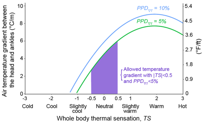
52 ANSI/ASHRAE Standard 55-2023
PDF Page 55
difference where the head level is warmer than the ankle level. Thermal stratification in the opposite direction is rare, is perceived more favorably by occupants, and is not addressed in this standard.
The allowable difference in air temperature from ankle level to head level is based on Figure I-3 and assumes that a maximum of 5% of occupants are dissatisfied by the vertical air stratification.
I5. FLOOR SURFACE TEMPERATURE
Occupants may feel uncomfortable due to contact with floor surfaces that are too warm or too cool. The temperature of the floor, rather than the material of the floor covering, is the most important factor for foot thermal comfort while wearing shoes. Figure I-4 gives the percentage of occupants expected to be dissatisfied due to floor temperature tf based on people wearing lightweight indoor shoes. Thus, it is acceptable to use these criteria for people wearing heavier footgear, as they will be conservative. This standard does not address the floor temperature required for people not wearing shoes, nor does it address satisfactory floor temperatures for people sitting on the floor.
The limit for floor temperature tf is based on Figure I-4 and assumes that a maximum of 10% of occupants are dissatisfied by warm or cold floors.
I6. TEMPERATURE VARIATIONS WITH TIME
Fluctuations in the air temperature and/or mean radiant temperature tr may affect the thermal comfort of occupants. Those fluctuations under the direct control of the individual occupant do not have a negative impact on thermal comfort, and the requirements of this standard do not apply to these fluctuations. Fluctuations that occur due to factors not under the direct control of the individual occupant (e.g., cycling from thermostatic control) may have a negative effect on comfort, and the requirements of this standard apply to these fluctuations. Fluctuations that occupants experience as a result of moving between locations with different environmental conditions are allowed by Section 5 of this standard as long as the conditions at all of these locations are within the comfort zone for these moving occupants.
I7. CYCLIC VARIATIONS
Cyclic variations refer to those situations where the operative temperature to repeatedly rises and falls and the period of these variations is not greater than 15 minutes. If the period of the fluctuation cycle exceeds 15 minutes, the variation is treated as a drift or ramp in operative temperature, and the requirements of Section 5.3.6.3 apply. In some situations, variations with a period not greater than 15 minutes are superimposed on variations with a longer period. In these situations, the requirements of Section 5.3.6.3 apply to the component of the variation with a period not greater than 15 minutes, and the requirements of Section 5.3.6.3 apply to the component of the variation with a period greater than 15 minutes.
I8. DRIFTS OR RAMPS
Temperature drifts and ramps are monotonic, noncyclic changes in operative temperature to . The requirements of Section 5.3.6.3 also apply to cyclic variations with a period greater than 15 minutes. Generally, “drifts” refer to passive temperature changes of the enclosed space, and “ramps” refer to actively controlled temperature changes.
Figure I-4 Local discomfort caused by warm and cool floors.
ANSI/ASHRAE Standard 55-2023 53
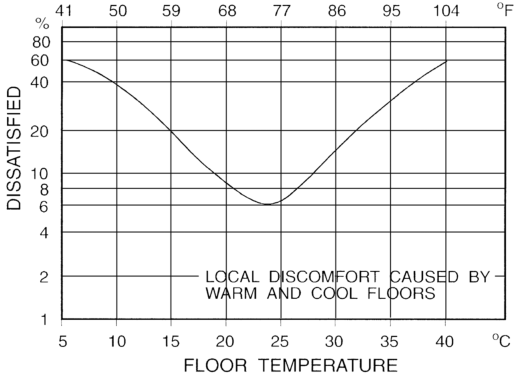
PDF Page 56
Section 5.3.6.3 specifies the maximum change in operative temperature to allowed during a period of time. For any given time period, the most restrictive requirements from Table 5-11 apply. For example, the operative temperature may not change more than 2.2°C (4.0°F) during a 1.0 hour period, and it also may not change more than 1.1°C (2.0°F) during any 0.25 hour period within that 1.0 hour period. If the user creates variations as a result of control or adjustments, higher values may be acceptable.
These local thermal comfort criteria were developed in order to keep the expected percent of occupants who are dissatisfied due to all of these local discomfort factors at or below 10%. The operative temperature to ranges required in the standard were developed in order to keep the predicted percent dissatisfied of occupants due to operative temperature only, without factoring in local thermal factors. When both local discomfort factors and operative temperature considerations are combined, the goal of this standard to standardize satisfactory thermal conditions for a substantial majority of occupants (80%) is achieved. This is especially true if there is some overlap between those who are dissatisfied due to local factors and those who are dissatisfied due to operative temperature.
54 ANSI/ASHRAE Standard 55-2023
PDF Page 57
(This appendix is not part of this standard. It is merely informative and does not contain requirements necessary for conformance to the standard. It has not been processed according to the ANSI require- ments for a standard and may contain material that has not been subject to public review or a consen- sus process. Unresolved objectors on informative material are not offered the right to appeal at ASHRAE or ANSI.)
INFORMATIVE APPENDIX J OCCUPANT-CONTROLLED NATURALLY CONDITIONED SPACES
For the purposes of this standard, occupant-controlled naturally conditioned spaces (see Section 5.4) are those spaces where the thermal conditions of the space are regulated primarily by the occupants through opening and closing of fenestration in the envelope. Field experiments have shown that occupants’ thermal responses in such spaces depend in part on the outdoor climate and may differ from thermal responses in buildings with centralized HVAC systems, primarily because of the different thermal experiences, changes in clothing, availability of control, and shifts in occupant expectations. This optional method is intended for such spaces.
In order for this optional method to apply, the space in question must be equipped with operable fenestration to the outdoors that can be readily opened and adjusted by the occupants of the space.
It is permissible to use mechanical ventilation with unconditioned air. Opening and closing of fenestration must be the primary means of regulating the thermal conditions in the space. It is permissible for the space to be provided with a heating and/or cooling system, but this optional method does not apply when the heating and/or cooling system is in operation. It applies only to spaces where the occupants are engaged in near-sedentary physical activities, with metabolic rates ranging from 1.0 to 1.3 met. This optional method applies only to spaces where the occupants are free to adapt their clothing to the indoor and/or outdoor thermal conditions. The permitted range of acceptable clothing must be at least as broad as 0.5 to 1.0 clo. Table J-1 shows example clothing ensembles that achieve 0.5 clo or lower.
For spaces that meet these criteria, it is acceptable to determine the allowable indoor operative temperatures to from Figure 5-9. This figure includes two sets of operative temperature limits, one for 80% satisfaction and one for 90% satisfaction. The 80% satisfaction limits are for typical applications. It is acceptable to use the 90% satisfaction limits when a higher standard of thermal comfort is desired. Figure 5-9 is based on an adaptive model of thermal comfort that is derived from a global database of 21,000 measurements taken primarily in office buildings.
The input variable in the adaptive model in Figure 5-9 is prevailing mean outdoor air temperature
t pma out
t pma out . This temperature is based on the arithmetic average of the mean daily outdoor temperatures over
some period of days. It represents the broader external climatic environment to which building occupants have become physiologically, behaviorally, and psychologically adapted. At its simplest, tpma out can be approximated by the climatically normal monthly mean air temperature from the most representative local meteorological station available. However, because days in the more remote past have less influence on the building occupants’ comfort temperature than more recent days, Equation J-1 should be used to calculate
tpma out
tpma out
:
tpma out = 1 - te n - 1 + trm n - 1
(J-1)
where te ( n - 1) is the mean daily outdoor temperature for the day before the day in question, trm ( n - 1) is the running mean temperature for the day before the day in question ( n - 1), and is a constant between 0 and 1 that controls the speed at which the running mean responds to changes in weather (outdoor temperature). Recommended values for are between 0.9 and 0.6, corresponding to a slow- and fast-response running mean, respectively. See Figure J-1 for examples. Adaptive comfort theory suggests that a slow-response running mean ( = 0.9) could be more appropriate for climates in which synoptic-scale (day-to-day) temperature dynamics are relatively minor, such as the humid tropics. But for midlatitude climates, where people are more familiar with synoptic-scale weather variability, a lower value of could be more appropriate. For example, if = 0.7, the prevailing mean outdoor temperature for today would be 30% of yesterday’s mean daily outdoor temperature plus 70% of yesterday’s running mean outdoor temperature. This form of the equation advances the value of the running mean from one day to the next and is convenient both for computer algorithms and for manual calculations. A value for running mean temperature has to be assumed for day one in order to seed the sequence, but from there it can be calculated with Equation J-1. The running mean may be initiated seven days prior to the start of the period of interest, and the actual daily mean outdoor temperature can be used for that first day to seed the sequence.
The allowable operative temperature to limits in Figure 5-9 may not be extrapolated to outdoor temperatures above and below the end points of the curves in this figure. If the prevailing mean outdoor temperature
ANSI/ASHRAE Standard 55-2023 55
PDF Page 58
Table J-1 Example Clothing Ensembles
Garment Description Iclu , clo Garment Description Iclu , clo
Sample Woman’s Ensemble Sample Man’s Ensemble
Bra 0.01 Men’s briefs 0.04
Panties 0.03 Shoes 0.02
Pantyhose/stockings 0.02 Calf-length socks 0.03
Shoes 0.02 Short-sleeve dress shirt 0.19
Short-sleeve dress shirt 0.19 Straight trousers (thin) 0.15
Skirt (knee-length thin) 0.14 Net, metal- or wooden-side arm chair 0.00
Net, metal- or wooden-side arm chair 0.00 Total 0.43
Total 0.41
Figure J-1 Exponentially weighted running mean outdoor temperature tpma out with set to 0.8 (slower responding) and 0.6 (faster responding).
56 ANSI/ASHRAE Standard 55-2023
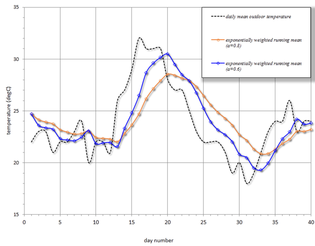
PDF Page 59
is less than 10°C (50°F) or greater than 33.5°C (92.3°F), this option may not be used, and no specific guidance for such conditions is included in this standard.
Figure 5-9 accounts for local thermal discomfort effects in typical buildings, so it is not necessary to address these factors when using this option. If there is reason to believe that local thermal comfort is a problem, it is acceptable to apply the criteria in Section 5.3.5.
Figure 5-9 also accounts for people’s clothing adaptation in naturally conditioned spaces by relating the satisfactory range of indoor temperatures to the outdoor climate, so it is not necessary to estimate the clothing values for the space. No humidity or air speed limits are required when this option is used.
Figure 5-9 includes the effects of people’s indoor air speed adaptation in warm climates, up to 0.3 m/s (59 fpm) in operative temperatures to warmer than 25°C (77°F). In naturally conditioned spaces where air speeds within the occupied zone exceed 0.3 m/s (59 fpm), the upper satisfactory temperature limits in Figure 5-9 are increased by the corresponding t 0 in Table 5-12, which is based on equal SET values as illustrated in Section 5.3.4. For example, increasing air speed within the occupied zone from 0.3 m/s (59 fpm) to 0.6 m/s (118 fpm) increases the upper satisfactory temperature limits in Figure 5-9 by a t 0 of 1.2°C (2.2°F). These adjustments to the upper satisfactory temperature limits apply only at t 0 > 25°C (77°F) in which the occupants are engaged in near sedentary physical activity (with metabolic rates between 1.0 met and 1.3 met).
ANSI/ASHRAE Standard 55-2023 57
PDF Page 60
(This appendix is not part of this standard. It is merely informative and does not contain requirements necessary for conformance to the standard. It has not been processed according to the ANSI require- ments for a standard and may contain material that has not been subject to public review or a consen- sus process. Unresolved objectors on informative material are not offered the right to appeal at ASHRAE or ANSI.)
INFORMATIVE APPENDIX K COMPLIANCE DOCUMENTATION TEMPLATE FOR THERMAL COMFORT
The Compliance Documentation Template for Thermal Comfort facilitates compliance with ASHRAE Standard 55, Section 6.2, and can be downloaded at www.ashrae.org/55Files (requires Microsoft Excel [®] ). This template documents design conditions for mechanically ventilated (Section 5.3) and naturally ventilated (Section 5.4) spaces and is designed to help ensure that buildings are used as intended by their representative occupants. The template is organized as follows:
- 6.2, Core Documentation Requirements: This tab focuses on the core requirements that are applicable to
both mechanically and naturally ventilated spaces. Here the user will be able to define the compliance method used for each space. For occupant-controlled naturally conditioned spaces, select Section 5.4 methodology. Otherwise, proceed with Section 5.3 methodology. Use the Add/Remove Rows buttons to document all required design comfort conditions.
- 5.3, Specific Documentation: Adhere to the instructions provided in each column to accurately complete
the required information.
- 5.4, Specific Documentation: This applies only to spaces that are naturally conditioned. Adhere to the
instructions provided in each column to accurately complete the required information.
Note: If any reasonably predictable representative occupants are excluded from compliance, they shall be
identified along with the rationale for their exclusion in the table located in the “Introduction” tab. This includes exclusion of representative occupants whose clothing and/or metabolic rate fall outside the applicable bounds of the standard, as well as transitory or temporary occupants. Similarly, any spaces that are excluded because they are unoccupied shall be listed in the table.
58 ANSI/ASHRAE Standard 55-2023
PDF Page 61
(This appendix is not part of this standard. It is merely informative and does not contain requirements necessary for conformance to the standard. It has not been processed according to the ANSI require- ments for a standard and may contain material that has not been subject to public review or a consen- sus process. Unresolved objectors on informative material are not offered the right to appeal at ASHRAE or ANSI.)
INFORMATIVE APPENDIX L MEASUREMENTS, SURVEYS, AND EVALUATION OF COMFORT IN EXISTING SPACES: PARTS 1 AND 2
L1. PHYSICAL MEASUREMENTS
L1.1 Overview of Comfort Prediction Using Physical Measurements. Measurements of indoor environmental parameters are converted to predictions of occupants’ thermal satisfaction through calculations and tests against comfort limits.
a. In the predicted-mean-vote-based (PMV) method (Section 5.3), environmental measurements are com bined with assumptions about clothing and activity level to calculate PMV, a measure of an average occupant’s thermal sensation. In Standard 55, comfort zone is defined as conditions falling within and including PMV levels from –0.5 PMV to +0.5 PMV.
At any given PMV level, a population’s proportion of dissatisfied members may be predicted via the predicted percentage dissatisfied (PPD) curve. This is an empirical probit fit of thermal sensation (TSENS) survey scores obtained in a range of test environments in which dissatisfaction was assumed to occur at TSENS absolute values of 2 or greater. With this method, a PMV of ±0.5 predicts 90% of a population satisfied, or a 10% PPD.
However, in most buildings this 90% satisfied rating is rarely obtained, with maximum satisfaction around 80%. The difference has been ascribed to discomfort perceived in local parts of the body. The probability of local discomfort is predicted by testing environmental parameters measured in sensitive locations against empirically determined limits. Rates of temperature change are also limited to avoid discomfort. Local discomfort effects are assumed to contribute an additional 10% PPD to the discomfort predicted by PMV, so that the total PPD expected in a building with PMV ±0.5 will be 20%. b. In the adaptive model, used for naturally ventilated spaces, environmental measurements are linked to
satisfaction through an empirical model in which the prevailing mean air outdoor temperature determines the position of percent satisfied contours bordering the comfort zone. Section 5.4 defines prevail- ing mean outdoor air temperature . Local discomfort limits are not used in the adaptive model.
L1.2 Environmental and Occupant Measurements. Environmental parameters are described in Section 5.1, and their measurement requirements are described in Section 7.3. For nonsteady conditions, the Section 7.3.3 prescribes measurement timing. The two personal parameters, activity level and clothing, must also be estimated for the occupants of the space. Estimation methods are presented in Informative Appendix F and Informative Appendix G. For evaluating a space, each of these parameters should be estimated in the form of mean values over a period of 0.25 to 1.0 hours immediately prior to measuring the indoor environmental parameters. If the occupants are not yet present, such as during design and commissioning, one may use clothing and activity values agreed upon by owners and designers as appropriate for the building’s function.
L2. SURVEYING OCCUPANTS
The use of occupant thermal environment surveys is an acceptable way of assessing comfort conditions for the satisfaction ranges discussed in this standard. With surveys, one may measure the percent who are “satisfied” or “comfortable” by putting those direct questions to a representative sample of the occupants. One may also obtain the percent satisfied using the ASHRAE thermal sensation scale, making the traditional assumption that satisfaction occurs when the seven-point scale is within TSENS = –1.5 satisfied +1.5 (when using a scale unit resolution of 0.5 or less) or –2 < satisfied < +2 (when the scale resolution is limited to integers).
Surveys obtain occupants’ comfort perceptions directly, whereas measurements of the environment predict those perceptions indirectly through models. However, surveys cannot be administered in all cases. Because surveys require engaging the occupants and consuming some of their time, it is necessary to have a well-planned communications approach and to use a survey that is optimized for length and content. The timing and frequency of repetition must also be weighed.
ANSI/ASHRAE Standard 55-2023 59
PDF Page 62
All surveys should strive for a representative sample size and a high response rate across the occupied space in the building. If the objective of the survey is to assess an entire building or installation, an adequate sample size and response rate help lower the risks of generalizing a limited observation to the entire occupant population. Section 7.3.1 prescribes minimum response rates for surveys. It is possible that in operating buildings, the perceptions of nonrespondents may be less important than those of respondents who take the time to answer the questions.
Thermal environment surveys are invaluable tools for diagnostic purposes in existing buildings and facilities. As a diagnostic tool, the goal is not a broad-brush assessment of environmental quality but rather a detailed insight into the building’s day-to-day operation through occupant feedback. For such purposes, each response is valuable, regardless of the size or response rate of the survey.
There are two types of thermal environment surveys. In either type of survey, the essential questions relate to thermal comfort, but additional questions can help identify problems and formulate possible responses.
L2.1 Point-in-Time Surveys. Point-in-time (“right-now”) surveys are used to evaluate occupants’ thermal experience at a single point in time. Thermal comfort researchers have used these surveys to correlate thermal comfort with environmental factors such as those included in the PMV model: metabolic rate, clothing insulation, air temperature, radiant temperature, air speed, and humidity.
A sample point-in-time survey is included in Figure L-1. It includes a thermal sensation survey that asks occupants to rate their sensation (from “hot” to “cold”) on the ASHRAE seven-point thermal sensation scale. The scale units are sometimes designated “TSENS.”
It also asks, “How satisfied are you with the thermal environment?” with a scale of “very dissatisfied” to “very satisfied.” The satisfaction scale is a standard psychometric test in other disciplines and is best divided into seven scale units.
Sometimes, preference scales for temperature and air movement are also used (e.g., these scales are common in the comfort field study database found in ASHRAE RP-884, Towards an Adaptive Model of Thermal Comfort and Preference ):
“Prefer to be:” “cooler/no change/warmer” “Prefer”: “less air movement/no change/more air movement”
In order to use the results of a point-in-time survey to assess satisfaction with the thermal environment over time, the survey must be implemented under multiple thermal conditions and in multiple building operating modes. The difficulty of arranging multiple surveys in workplace environments usually limits the feasibility of using the point-in-time survey approach for assessing comfort over time. This limitation may diminish with the use of Web-based and mobile applications oriented toward building operation.
L2.2 Satisfaction Surveys. A second form of thermal environment survey, a satisfaction survey, is used to evaluate thermal comfort response of the building occupants in a certain span of time. Instead of evaluating thermal sensations and environmental variables indirectly to assess percentage dissatisfied, this type of survey directly asks occupants to provide satisfaction responses.
An example thermal satisfaction survey is included in Figure L-2. It asks occupants to rate their satisfaction with their thermal environment (from “very dissatisfied” to “very satisfied”) on a seven-point satisfaction scale. The percentage of occupants satisfied is calculated from seven-point satisfaction survey scores by dividing the number of votes falling between +1 and +3, inclusive, by the total number of votes. The percentage of occupants dissatisfied is calculated from seven-point satisfaction survey scores by dividing the number of votes falling between –1 and –3, inclusive, by the total number of votes.
The premise of the satisfaction survey is that occupants can recall instances or periods of thermal discomfort, identify patterns in building operation, and provide “overall” or “average” comfort votes on their environment. The surveyor may identify a span of time for the respondents to consider, and the occupants provide the time integration. Questions to identify the nature (causes) of dissatisfaction may be included in satisfaction surveys (e.g., source-of-discomfort questions in Figure L-2).
As the thermal satisfaction survey assesses a long time frame, it should be administered every six months or repeated in heating and/or cooling seasons. In a new building, the first thermal satisfaction survey may be performed approximately six months after occupancy, late enough to avoid assessing the effects of building commissioning but early enough to help identify long-term building problems that have escaped detection in the commissioning process.
The thermal satisfaction survey can be used by researchers, building operators, and facility managers to assess building system performance in new buildings, and to perform periodic postoccupancy evaluation in existing facilities.
60 ANSI/ASHRAE Standard 55-2023
PDF Page 63
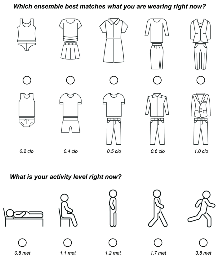
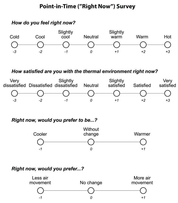
Figure L-1 Thermal environment point-in-time survey. Note: For all surveys, remove the numerical values under the scales before presenting the survey to occupants. They are used to code responses and analyze results in a standard manner.
PDF Page 64
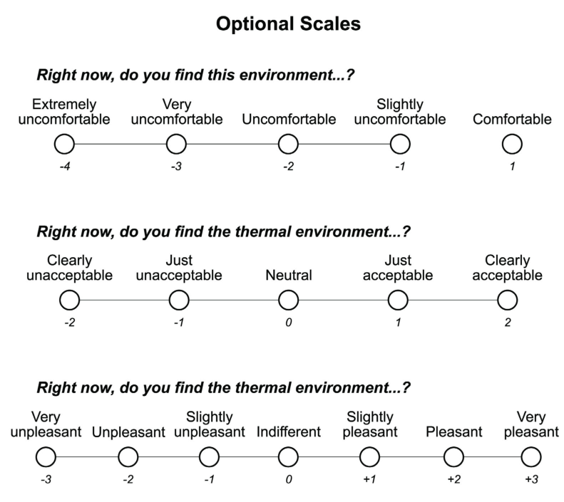
Figure L-1 (continued) Thermal environment point-in-time survey.
62 ANSI/ASHRAE Standard 55-2023
PDF Page 65
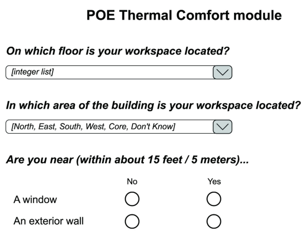
Figure L-2 Thermal environment satisfaction survey.
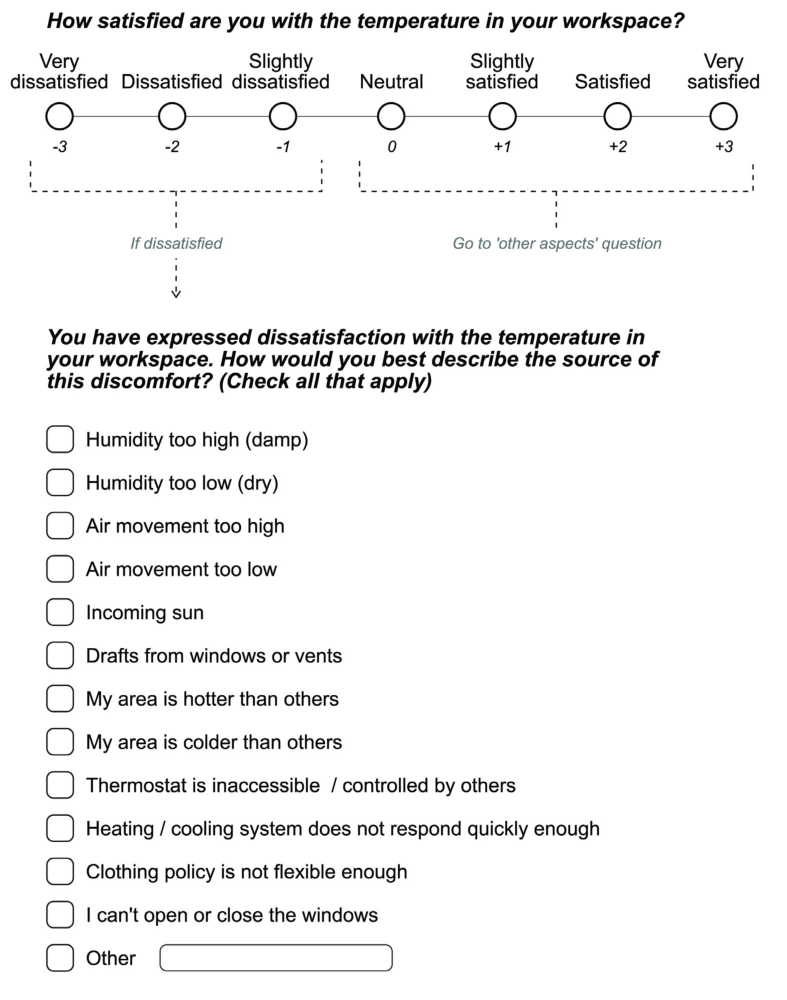
PDF Page 66
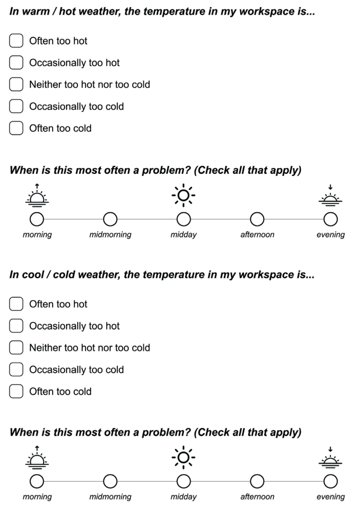
Figure L-2 (continued) Thermal environment satisfaction survey.
PDF Page 67
Table L-1 Comfort Evaluation Approaches for Various Applications
| Measurement Method | Occupant Surveys | Nature of Application | Col4 |
|---|---|---|---|
| Measurement Method | Occupant Surveys | Short-Term Long-Term | Short-Term Long-Term |
| Measurement Method | Occupant Surveys | Right-Now/Point-in-Time Survey (must survey relevant times and population): • Binning (TSENS scores) leads to % comfort exceedance during period of survey. • Needs coincident temperature to extrapolate to full range of conditions. (Used for research, problem diagnostics) | Occupant Satisfaction Survey: • Survey scores give % dissatisfied directly. (“dissatisfaction” may be interpreted to start either below –1, or below 0). • Time period of interest can be specified to survey takers. (Used for building management, commissioning, rating operators and real estate value, compliance with green building rating systems) |
| Measurement Method | Environmental Measurements | Spot Measurements, Temporary (Mobile) Sensors (must select a relevant time to measure): • Use measurements to determine PMV (Section 5.3). • Use measurements to determine compliance with adaptive model (Section 5.4). (Used for real-time operation, testing and validating system performance) | Logging Sensors over Period of Interest, or Trend Data from Permanently Installed (BAS) Sensors: • Exceedance hours: Sum of hours over PMV or adaptive model limits. • Binned exceedances may be weighted by their severity. • Instances of excessive rate-of-temperature change or of local thermal discomfort can be counted. (Used for evaluating system and operator performance over time) |
L3. EVALUATION OF COMFORT IN EXISTING SPACES
The evaluation approach depends on the intended application. The list of possible evaluation applications is extensive. They require evaluation over varying time periods, from short term (ST) to long term (LT):
a. Real-time operation of a building using comfort metrics (ST) b. Evaluating HVAC system performance (ST, LT) c. Building management decisions regarding upgrades, continuous commissioning, and rating the perfor mance of operators and service providers (LT) d. Real-estate portfolio management: rating building quality and value (LT, ST) e. Validating compliance with LEED existing-buildings requirements (ST, LT) f. Validating compliance with requirements of codes—energy, hospital, etc. (ST)
There are two main approaches to evaluating thermal comfort in operating buildings. One is to directly determine occupant thermal sensations and satisfaction through the statistical evaluation of occupant surveys. The other is to use comfort models to estimate sensations and satisfaction of the occupants from measured environmental variables. The measurements needed for each of these approaches are described in Sections L1 and L2.
Surveys and physical measurements may be used in combination with each other for the purpose of problem diagnosis and research (see Table L-1). In the short-term, point-in-time surveys are used to obtain comfort perceptions coincident with short-interval logged environmental measurements or BAS system trend data. For evaluating building performance over time, occupant satisfaction surveys results are correlated with averages of long-term measurements of environmental conditions.
L3.1 Analysis Based on Occupant Surveys. Surveys can assess comfort directly, in contrast to the indirect approach of calculating comfort through comfort models using measured environmental variables.
a. Short-Term Analyses (Using Instantaneous Comfort Determinations)
- Measures from Point-in-Time (“Right-Now”) Surveys i. Thermal acceptability votes ii. Thermal sensation (TSENS) votes (When averaged for a population, TSENS votes correspond
directly to PMV votes.) iii. Temperature preference votes and air-movement preference votes (“less”/“no change”/“more”) 2. Criteria for Passing i. –0.5 to +0.5 on the PMV scale, inclusive, is the Standard 55 criterion for passing ii. Field surveys usually consider TSENS values of –1 and +1 as representing “satisfied”; the break
along the categorical seven-point thermal sensation scale is at –1.5 and +1.5, inclusive. 3. Local Thermal Discomfort Determination i. Questions about any local thermal discomfort (e.g., ankle, neck discomfort) ii. Questions addressing solar radiation effects on comfort
ANSI/ASHRAE Standard 55-2023 65
PDF Page 68
b. Long-Term Analyses (Representing Time Periods Such as Season or Year): In an occupant satisfaction
survey, thermal environment questions apply over time (three to six months or more). The survey includes diagnostic questions to identify sources of dissatisfaction. Point-in-time surveys may be repeated over time to obtain a long-term record of comfort. Because occupants have other responsibilities and limited time, repeated surveys must be very short and quickly completed.
- Measures from Occupant Satisfaction Surveys i. Thermal satisfaction scale (“very satisfied” to “very dissatisfied”)
- Criteria for Passing i. From neutral (0 scale unit) to +3 (Votes below this range generally comprise 40% of a building’s total votes in the CBE survey benchmark database.) ii. Scale units –1 to +3 (Votes below this range generally comprise 20% of a building’s total votes in
the CBE survey benchmark database.) 3. Branching Dissatisfaction Questions (Count Responses and Tally by Category) i. Used to identify and correct problems. Analysis involves documenting the improvements made, resurveying the areas in which the problem occurred, and tallying the differences in responses obtained before and after the improvements. 4. Accumulated Scores from Repeated Point-in-Time Surveys i. If point-in-time surveys can be repeated sufficiently, the distribution of accumulated votes can be used to evaluate long-term comfort in the building. Such repetition becomes feasible, with short computer applications available to occupants via desktop and mobile devices.
L3.2 Analysis Based on Measurements of Environmental Variables. Environmental measurements are linked to occupant comfort through comfort models. Two comfort models, PMV and adaptive, are specific to mechanically conditioned and naturally ventilated buildings, respectively. Some mixed-mode buildings include a combination of both comfort model types. Active investigation is underway into how the two models apply in these cases.
The following measures and criteria underlie the documentation of comfort performance based on physical environmental measurements.
L3.2.1 Point-in-Time (Short-Term) Analyses
a. PMV Model
- Measures: PMV heat-balance model prediction of thermal sensation and satisfaction from environmental measurements are described in Section 5.3 (including air movement extension in Section 5.3.4). Limits to local thermal discomfort are described in Section 5.3.5, and rates of temperature change are described in Section 5.3.6.
- Criteria for Passing: –0.5 to +0.5 on the PMV scale, inclusive. This represents an estimated 90% satisfied with the thermal environment. Expressed as a comfort zone on a psychrometric chart, this represents a temperature range of 3 K to 5 K (5°F to 8°F), depending on clothing level and humidity. b. Local Thermal Discomfort Limits: Local thermal should, by itself, not exceed the limits prescribed in
Section 5.3.5. At a minimum, an assumed 10% dissatisfaction caused by local discomfort is added to PMV-predicted discomfort to obtain the overall thermal dissatisfaction of an environment. Solar radiation on occupants in neutral or warm conditions should not exceed 10% of outdoor solar radiation incident on the window. The best-practice upper limit is 5%. c. Adaptive Model (Section 5.4): The adaptive model is an empirical model of adaptive human responses
to environments offering operable window control. The comfort zone on a given day is dependent on a running mean of previous outdoor air temperatures to which people continuously adapt over time.
- Measures i. Air temperature indoors ii. Running mean of outdoor air temperature, defined in Section 3 as the prevailing mean outdoor air
temperature tpma out 2. Criteria for Passing i. An environmental condition passes if it is within the 80% boundaries predicted by the adaptive model. d. Limits to Rate of Environmental Change
- Measures i. Operative temperature to rate of change ii. Instances of rate-of-change exceedance within a defined time period
66 ANSI/ASHRAE Standard 55-2023
PDF Page 69
L3.2.2 Time-Integrated Analyses, (Long-Term over Typical Day, Season, or Year)
a. Measures
-
Trend logging of physical measurements over time
-
Temperature and humidity in the occupied zone. Globe temperature (temperature measured within a globe exposed to radiation exchange with surrounding surfaces) closely approximates operative temperature to in most indoor situations. For greater accuracy, globe temperature measurements may be combined with shielded air temperature measurements to calculate mean radiant temperature, which, when averaged with the shielded air temperature, provides operative temperature.
-
Measuring indoor air movement over time is very difficult and rarely done. In many indoor situations, the indoor air speed conforms to the still-air conditions of the PMV comfort zone (0.2 m/s [40 fpm]), in which case air speed measurement is not necessary.
-
The number of hours in which local discomfort may be expected is estimated using the local thermal discomfort limits in Section 5. Local discomfort exceedance hours are added to hours in which the comfort zone requirements are exceeded (exceedance occurs when |PMV| > 0.5). b. Criteria Metrics
-
The prescribed metric is the exceedance hour (semantically equivalent to discomfort hour) predicted during occupied hours within any time interval. See the definition in Section 3 and formulas in Section 7.4.2.2.1. Units are in hours. No limits are prescribed.
-
In addition, it is possible to account for the severity of exceedance at any time, using a metric analogous to the familiar degree-day. Weighted exceedance hours (equivalent to degree-of-discomfort hours) are the number of occupied hours within a defined time period in which the environmental conditions in an occupied zone are outside of the comfort zone boundary, weighted by the extent of exceedance beyond the boundary. Units are thermal sensation scale units times hours. The formula for the PMV comfort zone uses terms defined in Section 7.4.2.2.1:
WEH = [ Hdisc (|PMV| – 0.5)]
Units are thermal sensation scale units times hours. This is a useful metric but is not required in Standard 55. No limits are recommended. 3. Temperature-weighted exceedance hours: It may be useful to convert PMV comfort zone WEHs to a temperature-times-hours scale using the conversion 0.3 (thermal sensation scale units)/°C (0.15 [thermal sensation scale units]/°F). The unit for temperature-weighted exceedance hours is temperature times hours. This is a useful metric but is not required in Standard 55. No limits are recommended. 4. The WEH for the adaptive model also uses a temperature-times-hours scale:
WEH = [ H>upper ( Top - Tupper ) + H<lower ( Tlower - Top )]
This is a useful metric but is not required in Standard 55. No limits are recommended. 5. Expected number of episodes of discomfort, rate-of-change exceedances, and local discomfort exceedances within a time period of interest.
These are useful metrics but not required in Standard 55. No limits are recommended.
ANSI/ASHRAE Standard 55-2023 67
PDF Page 70
(This appendix is not part of this standard. It is merely informative and does not contain requirements necessary for conformance to the standard. It has not been processed according to the ANSI require- ments for a standard and may contain material that has not been subject to public review or a consen- sus process. Unresolved objectors on informative material are not offered the right to appeal at ASHRAE or ANSI.)
INFORMATIVE APPENDIX M INFORMATIVE REFERENCES AND BIBLIOGRAPHY
Arens, E., D. Heinzerling, G. Paliaga. 2018. Sunlight and indoor thermal comfort. ASHRAE Journal 7:12–21. Arens, E., S. Turner, H. Zhang, G. Paliaga. 2009. Moving air for comfort. ASHRAE Journal 5:18–28. Arens, E., T. Hoyt, X. Zhou, L. Huang, H. Zhang, and S. Schiavon. 2015. Modeling the comfort effects of
solar radiation indoors. Building and Environment 88:3–9. Arens, E., T. Xu, K. Miura, H. Zhang, M. Fountain, and F. Bauman. 1998. A study of occupant cooling by
personally controlled air movement. Energy and Buildings 27:45–59. ASHRAE. 1998. Towards an Adaptive Model of Thermal Comfort and Preference. ASHRAE RP-884. ASHRAE . 2006. ANSI/ASHRAE Standard 70-2006, Method of Testing for Rating the Performance of Air
Outlets and Inlets . Peachtree Corners, GA: ASHRAE. ASHRAE. 2009a. ANSI/ASHRAE Standard 113-2009, Method of Testing for Room Air Diffusion . Peachtree
Corners, GA: ASHRAE. ASHRAE. 2009b. ASHRAE Handbook—Fundamentals . Peachtree Corners, GA: ASHRAE. ASHRAE. 2013. Performance Measurement Protocols for Commercial Buildings: Best Practices Guide.
ASHRAE, Atlanta. ASHRAE. 2016. Standard 55 User’s Manual . Atlanta: ASHRAE. ASHRAE. 2019. ASHRAE Handbook—HVAC Applications. Peachtree Corners, GA: ASHRAE. Bean, R. and R. Mora. 2018. Prioritizing thermal comfort for homes: a case study in using Standard 55 for a
residential building. ASHRAE Journal . 60(9):28–40. Berglund, L.G. 1979. Thermal acceptability. ASHRAE Transactions 85(2):825–34. Berglund, L.G., and A.P. Gagge. 1979. Thermal comfort and radiant heat. Proceedings of the 3rd National
Passive Solar Conference of The American Section of The International Solar Energy Society, Inc . Berglund, L.G., and A.P.R. Fobelets. 1987. Subjective human response to low-level air currents and asym metric radiation. ASHRAE Transactions 93(1):497–523. Berglund, L.G., and R.R. Gonzalez. 1978a. Application of acceptable temperature drifts to built environ ments as a mode of energy conservation. ASHRAE Transactions 84(1):110–21. Berglund, L.G., and R.R. Gonzalez. 1978b. Occupant acceptability of eight-hour-long temperature ramps in
the summer at low and high humidities. ASHRAE Transactions 84(2):278–84. Bligh, J., and K.G. Johnson. 1973. Glossary of terms for thermal physiology. J. Appl. Physiol. 35941–61. Breunis, K., and J.P. deGroot. 1987. Relative humidity of the air and ocular discomfort in a group of suscep tible office workers. Proceedings of the Fourth International Conference on Indoor Air Quality and Cli- mate 2:625–29. de Dear, R.J., and G.S. Brager. 1998. Developing an adaptive model of thermal comfort and preference.
ASHRAE Transactions 104(1a):145–67. de Dear, R.J., and M.E. Fountain. 1994. Field experiments on occupant comfort and office thermal environ ments in a hot-humid climate. ASHRAE Transactions 100(2):457–75. Donnini, G., J. Molina, C. Martello, D.H.C. Lai, L.H. Kit, C.Y. Chang, M. Laflamme, V.H. Nguyen, and F.
Haghighat. 1996. Field study of occupant comfort and office thermal environment in a cold climate. Final Report of RP-821. ASHRAE, Atlanta. Fang, L., G. Clausen, and P.O. Fanger. 1998. Impact of temperature and humidity on the perception of indoor
air quality during immediate and longer whole-body exposure. Indoor Air 8:276–84. Fanger, P.O. 1982. Thermal Comfort . Malabar, FL: Robert E. Krieger Publishing Co. Fanger, P.O., A. K. Melikov, H. Hanzawa, and J. Ring. 1988. Air turbulence and sensation of draught.
Energy and Buildings 12:21–39. Fanger, P.O., B.M. Ipsen, G. Langkilde, B.W. Olesen, N.K. Christensen, and S. Tanabe. 1985. Comfort limits
for asymmetric thermal radiation. Energy and Buildings 8:225–36. Fanger, P.O., B.W. Olesen, G. Langkilde, and L. Banhidi. 1980. Comfort limits for heated ceilings. ASHRAE
Transactions 86(2):141–56. Fishman, D.S., and S.L. Pimbert. 1979. Survey of subjective responses to the thermal environment in
offices. Indoor Climate, P.O. Fanger and O. Valbjorn (eds.), Danish Building Research Institute, Copenhagen.
68 ANSI/ASHRAE Standard 55-2023
PDF Page 71
Fobelets, A.P.R., and A.P. Gagge. 1988. Rationalization of the effective temperature, ET*, as a measure of
the enthalpy of the human indoor environment. ASHRAE Transactions 94(1):12–31. Fountain, M., and C. Huizenga. 1995. “A Thermal Sensation Model for Use by the Engineering Profession.”
Final Report, ASHRAE RP-781. Prepared by Environmental Analytics, Piedmont, CA. for ASHRAE, Atlanta, GA. Fountain, M., and E. Arens. 1993. Air movement and thermal comfort. ASHRAE Journal August:26–30. Fountain, M., E. Arens, T. Xu, F.S. Bauman, and M. Oguru. 1996. An investigation of thermal comfort at
high humidities. Final Report of RP-860. ASHRAE, Atlanta. Gagge, A.P., and R.G. Nevins. 1976. Effect of energy conservation guidelines on comfort, acceptability and
health, Final Report of Contract co-04-51891-00, Federal Energy Administration. Gagge, A.P., Y. Nishi, and R.G. Nevins. 1976. The role of clothing in meeting FEA energy conservation
guidelines. ASHRAE Transactions 82(2):234–47. Griffiths, I.D., and D.A. McIntyre. 1974. Sensitivity to temporal variations in thermal conditions. Ergonom-
ics 17:499–507. Goldman, R.F. 1978. The role of clothing in achieving acceptability of environmental temperatures between
65°F and 85°F (18°C and 30°C). Energy Conservation Strategies in Buildings, J.A.J. Stolwijk, (Ed.) Yale University Press, New Haven. Gong, N., K.W. Tham, A.K. Melikov, D.P. Wyon, S.C. Sekhar, and D.K.W Cheong. 2005. Human percep tion of local air movement and the acceptable air velocity range for local air movement in the tropics. Proceedings of Indoor Air 2005, Beijing, China, pp. 452–56. Gong, N., K.W. Tham, A.K. Melikov, D.P. Wyon, S.C. Sekhar, D.K.W Cheong. 2006. The acceptable air
velocity range for local air movement in the tropics. HVAC&R Research 12(4):1065–76. Gonzalez, R.R., Y. Nishi, A. P. Gagge. 1974. Experimental evaluation of standard effective temperature - a
new biometeorological index of man’s thermal discomfort. International Journal of Biometeorology 18(1):1–15. Hanzawa, H., A.K. Melikov, and P.O. Fanger. 1987. Airflow characteristics in the occupied zone of venti lated spaces. ASHRAE Transactions 93(1):524–39. Havenith, G., S.G. Hodder, Y. Ouzzahra, D. Loveday, K. Kuklane, K. Lundgren, J. Fan, Y. Au. 2013.
ASHRAE RP-1504, Extension of the Clothing Insulation Database for Standard 55 and ISO 7730 to Provide Data for Non-western Clothing Ensembles, Including Data on the Effect of Posture and Air Movement on That Insulation. Final Report. Peachtree Corners, GA: ASHRAE. Havenith, G. S.G. Hodder. 2022. ASHRAE RP-1760, Part 2: Update of Clothing Insulation Database for
Western Clothing Ensembles, Including Effects of Posture, Body Movement and Air Velocity. Medical Clothing. Final Report. Peachtree Corners, GA: ASHRAE. Humphreys, M. 1978. Outdoor temperatures and comfort indoors. Building Research and Practice 6(2):92–
ISO. 1998. ISO 7726, Ergonomics of the Thermal Environment—Instruments for Measuring Physical Quan-
tities . Geneva Switzerland: International Organization for Standardization. ISO. 2005. ISO 7730, Ergonomics of the Thermal Environment—Analytical Determination and Interpreta-
tion of Thermal Comfort using Calculation of the PMV and PPD Indices and Local Thermal Comfort Criteria . Geneva Switzerland: International Organization for Standardization. Jones, B.W., K. Hsieh, and M. Hashinaga. 1986. The effect of air velocity on thermal comfort at moderate
activity levels. ASHRAE Transactions 92(2b):761–69. Kubo, H., N. Isoda, and H. Enomoto-Koshimizu. 1997. Cooling effect of preferred air velocity in muggy
conditions. Building and Environment 32(3):211–18. Lammers, J.T.H., L.G. Berglund, and J.A.J. Stolwijk. 1978. Energy conservation and thermal comfort in a
New York City high rise office building. Environmental Management 2:113–17. Laviana, J.E., F.H. Rohles, and P.E. Bullock. 1988. Humidity, comfort and contact lenses. ASHRAE Transac-
tions 94(1):3–11. Li, P., T. Parkinson, G. Brager, S. Schiavon, T.C.T. Cheung, T. Froese. 2019. A Data-driven approach to
defining acceptable temperature ranges in buildings. Building and Environment 153 (15): 302–12. Licina, V.F. et al. 2018. Development of the ASHRAE Global Thermal Comfort Database II. Building and
Environment 142:502–12. Liu, S., S. Schiavon, A. Kabanshi, W. Nazaroff. 2016. Predicted percentage of dissatisfied with ankle draft.
Indoor Air 27(4):852–62. doi: doi.org/10.1111/ina.12364. www.escholarship.org/uc/item/9076254n
ANSI/ASHRAE Standard 55-2023 69
PDF Page 72
Liu, S., Z. Wang, S. Schiavon, Y. He, M. Luo, H. Zhang, E. Arens. 2020. Predicted percentage of dissatisfied
with vertical air temperature gradient. Energy and Buildings P.110085. doi: doi.org/10.1016/ j.enbuild.2020.110085. www.escholarship.org/uc/item/0s76t57k. Matsuzaki, R., E. Mihake, Y. Miyashita, and S. I. Tanabe. 2019. Optimum indoor thermal comfort condi tions required after entering a room from outdoor summer heat. Tokyo, Japan: Waseda University. McCullough, E.A., and D.P. Wyon. 1983. Insulation characteristics of winter and summer indoor clothing.
ASHRAE Transactions 89(2b):614–33. McCullough, E.A., B.W. Jones, and J. Huck. 1985. A comprehensive data base for estimating clothing insu lation. ASHRAE Transactions 91(2a):29–47. McCullough, E.A., B.W. Olesen, and S. Hong. 1994. Thermal insulation provided by chairs. ASHRAE
Transactions 100(1):795–802. McIntyre, D.A. 1976. Overhead radiation and comfort. The Building Services Engineer 44:226–32. McIntyre, D.A. 1978. Preferred air speeds for comfort in warm conditions. ASHRAE Transactions
84(2):264–77. McNall, P.E., Jr., and R.E. Biddison. 1970. Thermal and comfort sensations of sedentary persons exposed to
asymmetric radiant fields. ASHRAE Transactions 76(1):123–36. McNall, P.E., Jr., J. Jaax, F.H. Rohles, R.G. Nevins, and W. Springer. 1967. Thermal comfort (thermally neu tral) conditions for three levels of activity. ASHRAE Transactions 73(1):I.3.1-I.3.14. Melikov, A.K., H. Hanzawa, and P.O. Fanger. 1988. Airflow characteristics in the occupied zone of heated
spaces without mechanical ventilation. ASHRAE Transactions 94(1):52–70. Mihara, K., C. Sekhar, K. W. Tham, Y. Takemasa, and B. Lasternas. 2019. Effects of temperature, air move ment and initial metabolic rate on thermal sensation during transient state in the tropics. Building and Environment 155:70–82. Mishra, A.K., M.G.L.C. Loomans, and J.L.M. Hensen. 2016. Thermal comfort of heterogeneous and
dynamic indoor conditions—An overview. Building and Environment 109:82–100. Miura M., and Ikaga T. 2016. Human response to the indoor environment under fluctuating temperature. Sci-
ence and Technology of the Built Environment 22: 820–30. Mora, R. and Meteyer, M, 2019. Thermal comfort in health care settings. ASHRAE Journal 61(7):10–19. Nevins, R.G., and A.M. Feyerherm. 1967. Effect of floor surface temperature on comfort: Part IV, cold
floors. ASHRAE Transactions 73(2):III.2.1-III.2.8. Nevins, R.G., K.B. Michaels, and A.M. Feyerherm. 1964. The effect of floor surface temperature on com fort: Part II, College age females. ASHRAE Transactions 70:37–43. Nicol, J.F., and M. Humphreys. 2002. Adaptive thermal comfort and sustainable thermal standards for build ings. Energy and Buildings 34(6):563–72. Nicol, J.F., M. Humphreys, and S. Roaf. 2012. Adaptive Thermal Comfort: Principles and Practice . Lon don: Routledge. Nielsen, B., I. Oddershede, A. Torp, and P.O. Fanger. 1979. Thermal comfort during continuous and inter mittent work. Indoor Climate, P.O. Fanger and O. Valbjorn, eds., Danish Building Research Institute, Copenhagen, pp. 477–90. Olesen, B.W. 1985. A new and simpler method for estimating the thermal insulation of a clothing ensemble.
ASHRAE Transactions 91(2b):478–92. Olesen, B.W. 1977. Thermal comfort requirements for floors. Proceedings of The Meeting of Commissions
B1, B2, E1 of IIR, Belgrade, pp. 337–43. Olesen, B.W. 1977. Thermal comfort requirements for floors occupied by people with bare feet. ASHRAE
Transactions 83(2):41–57. Olesen, S., P.O. Fanger, P.B. Jensen, and O.J. Nielsen. 1972. Comfort limits for man exposed to asymmetric
thermal radiation. CIB Commission W 45 Symposium, Thermal Comfort and Moderate Heat Str ess, Watford, U.K. (Published by HMSO London 1973). Olesen, B.W., E. Mortensen, J. Thorshauge, and B. Berg-Munch. 1980. Thermal comfort in a room heated
by different methods. ASHRAE Transactions 86(1):34–48. Olesen, B.W., M. Scholer, and P.O. Fanger. 1979. Discomfort caused by vertical air temperature differences.
Indoor Climate, P.O. Fanger and O. Valbjorn, eds., Danish Building Research Institute, Copenhagen. Parkinson, T., H. Zhang, E. Arens, Y. He, R. de Dear, J. Elson, A. Parkinson, C. Maranville, and A. Wang.
- Predicting thermal pleasure experienced in dynamic environments from simulated cutaneous thermoreceptor activity. Indoor Air 31(6):2266–228. Parkinson, T., and R. de Dear. 2015. Thermal pleasure in built environments: Physiology of alliesthesia.
Building Research & Information 43(3):288–301.
70 ANSI/ASHRAE Standard 55-2023
PDF Page 73
Parkinson, T., R. de Dear, and G. Brager. 2020. Nudging the adaptive thermal comfort model. Energy and
Buildings 206 (January). doi: https://doi:10.1016/j.enbuild.2019.109559. Porras-Salazar, J.A., S. Schiavon, P. Wargocki, T. Cheung, and K.W. Tham. 2022. Meta-analysis of 35 studies
examining the effect of indoor temperature on office work performance. Building and Environment 203. Rohles, F.H., J.E. Woods, and R.G. Nevins. 1974. The effect of air speed and temperature on the thermal sen sations of sedentary man. ASHRAE Transactions 80(1):101–19. Rohles, F.H., S.A. Konz, and B.W. Jones. 1983. Ceiling fans as extenders of the summer comfort envelope.
ASHRAE Transactions 89(1a):245–63. Rohles, F.H., G.A. Milliken, D.E. Skipton, and I. Krstic. 1980. Thermal comfort during cyclical temperature
fluctuations. ASHRAE Transactions 86(2):125–40. Rohles, F.H., Jr., J.E. Woods, and R.G. Nevins. 1973. The influence of clothing and temperature on seden tary comfort. ASHRAE Transactions 79:71–80. Scheatzle, D.G., H. Wu, and J. Yellott. 1989. Extending the summer comfort envelope with ceiling fans in
hot, arid climates. ASHRAE Transactions 95(1):269–80. Schiavon, S., and A.K. Melikov. 2009. Introduction of a Cooling Fan Efficiency Index. HVAC&R Research
5(6):1121–41. Schiavon, S., and K.H. Lee. 2013. Dynamic predictive clothing insulation models based on outdoor air and
indoor operative temperatures. Building and Environment 59:250–60. Schiller, G., E. Arens, F. Bauman, C. Benton, M. Fountain, and T. Doherty. 1988. A field study of thermal
environments and comfort in office buildings. ASHRAE Transactions 94(2):280–308. Schweiker, M., M. André, F. Al-Atrash, H. Al-Khatri, R.R. Alprianti, H. Alsaad, R. Amin, E. Ampatzi, A.Y.
Arsano, E. Azar, B. Bannazadeh, A. Batagarawa, S. Becker, C. Buonocore, B. Cao, J.-H. Choi, C. Chun, H. Daanen, S.A. Damiati, L. Daniel, …, Z. Zomorodian. 2020. Evaluating assumptions of scales for subjective assessment of thermal environments—Do laypersons perceive them the way, we researchers believe? Energy and Buildings 211. Smallcombe, J.W., G. Havenith, S.G. Hodder, D. Loveday, K. Kuklane, J. Petersson, A. Halder, and M. Mly narczyk. 2022. ASHRAE RP-1760, Part 1: Update of Clothing Insulation Database for Western Clothing Ensembles, Including Effects of Posture, Body Movement and Air Velocity. Peachtree Corners, GA: ASHRAE. Sprague, C.H., and P.E. McNall, Jr. 1971. Effects of fluctuating temperature and relative humidity on the
thermal sensation (thermal comfort) of sedentary subjects. ASHRAE Transactions 77:183–99. Tanabe, S., and K. Kimura. 1989. Thermal comfort requirements under hot and humid conditions. Proceed-
ings of the First ASHRAE Far East Conference on Air Conditioning in Hot Climates, Singapore, pp. 3–21. Tanabe, S., E. Arens, F. Bauman, H. Zhang, and T. Madsen. 1994. Evaluating thermal environments by
using a thermal manikin with controlled skin surface temperature. ASHRAE Transactions 100(1):39–48. Toftum, J. 2004. Air movement—Good or bad? Indoor Air 14:40–5. Wyon, D.P., Th. Asgeirsdottir, P. Kjerulf-Jensen, and P.O. Fanger. 1973. The effects of ambient temperature
swings on comfort, performance and behavior. Arch. Sci. Physiol. 27:441–58. Zhai, Y., C. Elsworth, E. Arens, H. Zhang, Y. Zhang, and L. Zhao. 2015. Using air movement for comfort
during moderate exercise. Building and Environment 94: 344–52. http://escholarship.org/uc/item/ 6018h6wz. Zhai, Y., F. Miao, L. Yang, S. Zhao, H. Zhang, and E. Arens. 2019. Using personally controlled air move ment to improve comfort after simulated summer commute. Building and Environment 165. Zhai, Y., S. Zhao, L. Yang, N. Wei, Q. Xu, H. Zhang, and E. Arens. 2019. Transient human thermophysio logical and comfort responses indoors after simulated summer commutes. Building and Environment 165. doi: https://doi.org/10.1016/j.buildenv.2019.04.023. Zhang, H., E. Arens, S. Abbaszadeh Fard, C. Huizenga, G. Paliaga, G. Brager, and L. Zagreus. 2007. Air
movement preferences observed in office buildings. International Journal of Biometeorology 51:349–60. Zhang, H., E. Arens, and Y. Zhai. 2015. A review of the corrective power of personal comfort systems in
non-neutral ambient environments. Building and Environment 91:15–41. doi: https://doi.org/10.1016/ j.buildenv.2015.03.013 Zhao, R., S. Sun, and R. Ding. 2004. Conditioning strategies of indoor environment in warm climates.
Energy and Buildings 36:1281–86.
ANSI/ASHRAE Standard 55-2023 71
PDF Page 74
(This appendix is not part of this standard. It is merely informative and does not contain requirements necessary for conformance to the standard. It has not been processed according to the ANSI requirements for a standard and may contain material that has not been subject to public review or a consensus process. Unresolved objectors on informative material are not offered the right to appeal at ASHRAE or ANSI.)
INFORMATIVE APPENDIX N ADDENDA DESCRIPTION
ANSI/ASHRAE Standard 55-2023 incorporates ANSI/ASHRAE Standard 55-2020 and Addenda a, b, c, d, e, f, g, h, i, j, and k to ANSI/ ASHRAE Standard 55-2020. Table N-1 lists each addendum and describes the way in which the standard is affected by the change. It also lists the ASHRAE and ANSI approval date for each addendum.
Table N-1 Addenda to ANSI/ASHRAE Standard 55-2020
| Addendum | Section(s) Affected | Description of Changes* | ASHRAE/ANSI Approval Dates |
|---|---|---|---|
| a | 3, 5.3.3.4 | Addendum a adds a new method for the assessment of local thermal discomfort with vertical air temperature gradient between the head level and ankle level. | April 30, 2021 |
| b | 5.2.1.4, 5.2.2.2, Table 5-5, 5.3.1.1, 5.3.2.1, Informative Appendices F, G, H | Addendum b changes the upper metabolic rate limit for the standard from 2 to 4. This change aligns the standard with ISO Standard 773 and is motivated by consistent recent research that supports the applicability of Standard 55 at this metabolic level. | Addendum b changes the upper metabolic rate limit for the standard from 2 to 4. This change aligns the standard with ISO Standard 773 and is motivated by consistent recent research that supports the applicability of Standard 55 at this metabolic level. |
| c | 5.3.2.1, Normative Appendix D | Addendum c changes the lower limit of average air speed when using the Elevated Air Speed Comfort Zone Method from 0.2 m/s to 0.1 m/s. | Addendum c changes the lower limit of average air speed when using the Elevated Air Speed Comfort Zone Method from 0.2 m/s to 0.1 m/s. |
| d | 3, 7.3.2(b), C1, C2(h), Tables C-1 and C-2 | Addendum d makes changes to the ERF code. The new code allows the user to calculate ERF and delta mean radiant temperature for an additional body position: horizontal. | October 29, 2021 |
| e | Informative Appendix J | Addendum e changes the paragraph that describes the basis for the calculation of prevailing mean temperature in Section 5.4.2.1. This change eliminates an equation that is easily misused and leaves a functionally equivalent equation that cannot be misused | June 30, 2021 |
| f | 3, 5.2.2.2, Normative Appendix B, Informative Appendix G | Addendum f changes the air speed definition to account for moving occupants. Additionally, activity-generated air speed and clothing insulation adjustment for an active person are now included within the PMV code of Normative Appendix B, in order to align with ISO 7730 and the original intent of the PMV model. | Addendum f changes the air speed definition to account for moving occupants. Additionally, activity-generated air speed and clothing insulation adjustment for an active person are now included within the PMV code of Normative Appendix B, in order to align with ISO 7730 and the original intent of the PMV model. |
| g | 3, Table D-1, D4, | Addendum g makes changes to the definition of the SET temperature and to the SET code to align with international standards | April 29, 2022 |
| h | See note. | Addendum h adds a new definition for “comfort zone” and updates related definitions; removes the concept of a separate elevated airspeed “method” and replaces it with a reference to an “adjustment” to the standard method (includes changes to Normative Appendix A, where a flow chart is added to guide users through the various models that underpin the standard; replaces the word “acceptable” with “satisfactory” throughout the standard; rewrites Informative Appendix H to account for recent changes in the standard and to better explain the concept of comfort zones; and updates the example surveys provided in Informative Appendix L and associated language. (NOTE: The changes in this addendum are too numerous to list here; download Addendum h at www.ashrae.org/addenda. | December 30, 2022 |
| i | 8 | Addendum i updates normative references to updated versions of ASHRAE publications. | April 28, 2023 |
| j | 6.1, 6.2, 6.2.1, 6.2.2, 6.2.3 (new) | Addendum j updates Section 6 of the standard to align with changes in Section 5 of the standard and to clarify aspects of required documentation that were previously confusing. In particular, Section 6 is now split into three sections that provide documentation requirements for Section 5.3 separate from 5.4 and separate from common requirements. Example documentation in Excel format is included as an online supplemental file, which replaces the example form that was in Appendix K. | October 31, 2023 |
| k | Table D-1, D4 | Addendum k modifies the SET code to account for body position. | October 31, 2023 |
- These descriptions may not be complete and are provided for information only.
PDF Page 75
POLICY STATEMENT DEFINING ASHRAE’S CONCERN FOR THE ENVIRONMENTAL IMPACT OF ITS ACTIVITIES
ASHRAE is concerned with the impact of its members’ activities on both the indoor and outdoor environment. ASHRAE’s members will strive to minimize any possible deleterious effect on the indoor and outdoor environment of the systems and components in their responsibility while maximizing the beneficial effects these systems provide, consistent with accepted Standards and the practical state of the art.
ASHRAE’s short-range goal is to ensure that the systems and components within its scope do not impact the indoor and outdoor environment to a greater extent than specified by the Standards and Guidelines as established by itself and other responsible bodies.
As an ongoing goal, ASHRAE will, through its Standards Committee and extensive Technical Committee structure, continue to generate up-to-date Standards and Guidelines where appropriate and adopt, recommend, and promote those new and revised Standards developed by other responsible organizations.
Through its Handbook, appropriate chapters will contain up-to-date Standards and design considerations as the material is systematically revised.
ASHRAE will take the lead with respect to dissemination of environmental information of its primary interest and will seek out and disseminate information from other responsible organizations that is pertinent, as guides to updating Standards and Guidelines.
The effects of the design and selection of equipment and systems will be considered within the scope of the system’s intended use and expected misuse. The disposal of hazardous materials, if any, will also be considered.
ASHRAE’s primary concern for environmental impact will be at the site where equipment within ASHRAE’s scope operates. However, energy source selection and the possible environmental impact due to the energy source and energy transportation will be considered where possible. Recommendations concerning energy source selection should be made by its members.
PDF Page 76

ASHRAE · 180 Technology Parkway · Peachtree Corners, GA 30092 · www.ashrae.org
About ASHRAE
Founded in 1894, ASHRAE is a global professional society committed to serve humanity by advancing the arts and sciences of heating, ventilation, air conditioning, refrigeration, and their allied fields.
As an industry leader in research, standards writing, publishing, certification, and continuing education, ASHRAE and its members are dedicated to promoting a healthy and sustainable built environment for all, through strategic partnerships with organizations in the HVAC&R community and across related industries.
To stay current with this and other ASHRAE Standards and Guidelines, visit www.ashrae.org/standards, and connect on LinkedIn, Facebook, Twitter, and YouTube.
Visit the ASHRAE Bookstore
ASHRAE offers its Standards and Guidelines in print, as immediately downloadable PDFs, and via ASHRAE Digital Collections, which provides online access with automatic updates as well as historical versions of publications. Selected Standards and Guidelines are also offered in redline versions that indicate the changes made between the active Standard or Guideline and its previous edition. For more information, visit the Standards and Guidelines section of the ASHRAE Bookstore at www.ashrae.org/bookstore.
IMPORTANT NOTICES ABOUT THIS STANDARD
To ensure that you have all of the approved addenda, errata, and interpretations for this Standard, visit www.ashrae.org/standards to download them free of charge.
Addenda, errata, and interpretations for ASHRAE Standards and Guidelines are no longer distributed with copies of the Standards and Guidelines. ASHRAE provides these addenda, errata, and interpretations only in electronic form to promote more sustainable use of resources.
Product code: 86897 11/23