855773520-LEED-v5-ID-C-Reference-Guide-Launch-Edition-1 - Full Extract
PDF Page 1
APRIL 2025 LAUNCH EDITION
LEED v5 REFERENCE GUIDE
INTERIOR DESIGN AND CONSTRUCTION
PDF Page 2
COPYRIGHT Copyright © 2025 by the U.S. Green Building Council. All rights reserved.
The U.S. Green Building Council, Inc. (USGBC) devoted significant time and resources to creating this LEED v5 Reference Guide for Interior Design and Construction, April 2025 Launch Edition. USGBC authorizes individual use of the Reference Guide. In exchange for this authorization, the user agrees: to retain all copyright and other proprietary notices contained in the Reference Guide; not to sell or modify the Reference Guide; and not to reproduce, display, or distribute the Reference Guide in any way for any public or commercial purpose, including display on a website or in a networked environment.
Unauthorized use of the Reference Guide violates copyright, trademark, and other laws and is prohibited.
USGBC reproduces the text of the federal and state codes, regulations, voluntary standards, etc., in the Reference Guide under license or, in some instances, in the public domain. USGBC owns all other text, graphics, layout, and other elements of content in the Reference Guide and are protected by copyright under both U.S. and foreign laws.
NOTE: Redistributing the Reference Guide on the internet or through other digital means is STRICTLY prohibited, even if offered free of charge.
THE USER MAY NOT COPY OR DISTRIBUTE DOWNLOADS OF THE REFERENCE GUIDE. THE USER OF THE REFERENCE GUIDE MAY NOT ALTER, REDISTRIBUTE, UPLOAD, OR PUBLISH THIS REFERENCE GUIDE IN WHOLE OR IN PART, AND HAS NO RIGHT TO LEND OR SELL THE DOWNLOAD OR COPIES OF THE DOWNLOAD TO OTHER PERSONS.
DISCLAIMER None of the parties involved in the funding or creation of the Reference Guide, including USGBC, its members, its contractors, or the U.S. government, assume any liability or responsibility to the user or any third parties for the accuracy, completeness, or use of or reliance on any information contained in the Reference Guide, or for any injuries, losses, or damages (including, without limitation, equitable relief) arising from such use or reliance.
Although we believe the information in the Reference Guide is reliable and accurate, we provide all materials within it without warranties of any kind, either express or implied, including, but not limited to, warranties of the accuracy or completeness of information in the training or the suitability of the information for any particular purpose.
As a condition of use, the user covenants not to sue and agrees to waive and release the U.S. Green Building Council, its members, its contractors, and affiliated organizations from any and all claims, demands, and causes of action for any injuries, losses, or damages (including, without limitation, equitable relief) that the user may now or hereafter have a right to assert against such parties as a result of the use of, or reliance on, the Reference Guide.
U.S. Green Building Council 2101 L Street, NW, Suite 600 Washington, DC 20037
TRADEMARK LEED® is a registered trademark of the U.S. Green Building Council. LEED v5 Reference Guide for Interior Design and Construction April 2025 Edition ISBN 979-8-99251-10-1-7
i
PDF Page 3
ACKNOWLEDGMENTS The development of LEED v5 has been made possible through the efforts of many dedicated volunteers, staff members, and others in the USGBC community. Collaborative and consensus-based development is a critical aspect of LEED, and our members are central to the success of our mission at all scales of involvement ranging from visioning to development to implementation. We are deeply grateful to these dedicated individuals whose contributions played a pivotal role in reaching this milestone release.
The LEED v5 rating systems were developed by the USGBC volunteer community and formally ratified by our broader membership. The reference guide suite is the product of the dedicated efforts of USGBC and Green Business Certification Inc. (GBCI) staff and consultants, designed to support the industry’s understanding and implementation of the rating systems.
LEED COMMITTEE MEMBERS Chairs listed in bold .
LEED Steering Committee
Barry Abramson Fernando Arias Eden Brukman Stewart Comstock Lance Davis Sarah Enaharo Emily English Brian Gilligan Tony Goodman Sarah Gudeman Josh Jacobs Adam Jennings Emma Jones Michael Karasoulas Ibrahim Kronfol Kavita Kumari Anica Landreneau Patty Lloyd Esteban Martinez Lena Ohta Robert Pickering Rock Ridolfi Jesse Rosenbluth Benjamin Roush Lourdes Salinas Jennifer Sanguinetti Chris Schaffner Shana Scheiber Tim Smith Allison Smith Adam Stoker Lisa Storer Brittany Storm Sarah Talkington Matt Van Duinen Kristen Walson Erica Weeks Jennifer Wolf Stefanie Young
LEED Technical Committee
Barry Abramson Michele Adams Jamy Bacchus Patrick Boyle Sandra Brock Yichao Chen Priscilla Chew Penny Cole Greg Collins Marc Coudert Michael Cudahy Amornrut Detudomsap Isabela Dib Emily English Ken Filarski Andrea Fornasiero Gwen Fuertes Cristine Gibney Tony Goodman Sarah Gudeman Josh Hatch Carrie Havey Julie Hendricks Tia Heneghan Kavita Karmarkar Dirk Kestner Ibrahim Kronfol Patty Lloyd Dirk Mason Doug Mazeffa Anna McWilliams Benjamin Meyer Rachel Nicely Lena Ohta William Paddock Greg Patton Louisa Rettew Rock Ridolfi Neil Rosen Jesse Rosenbluth Jennifer Sheffield Allison Smith Tim Smith Marilyn Specht Raphael Sperry
Peter Stair Nate Steeber Lisa Storer Sarah Talkington Raja Tannous Ted Tiffany Kapil Upadhyaya Stefanie Young
LEED Advisory Committee (LAC)
Keith Amann Michael Arny Heidimarie Bonilla de Cienfuegos Candice Bullard Sue Clark Lance Davis Peter Doo Crissy Haley Daniel Huard Jonathan Flaherty Miranda Gardiner Candice Goldsmith Ana Lucia Granda Sara Greenwood Geoff Hurst Blake Jackson Cara Kennedy Melanie Larkins Anica Landreneau Theresa Lehman Pamela Lippe Sarah Michelman Gautami Palanki Jonathan Rowe Alicia Silva Rebecca Stafford Melissa Targett Cesar Ulises Trevino
ii
PDF Page 4
CONSENSUS COMMITTEES Chairs listed in bold .
Design and Construction
Rachel Berkin Amy Costello Jennifer Emrick Marsha Gentile Geoff Hurst Lindsey Landwehr-Fasules Patty Lloyd Grace Manuel Eliza Mauro Bradley Nies Maria Perez Angi Rivera Stacy Simpson Rebecca Stafford Adam Stoker Melissa Targett Megan White
TECHNICAL ADVISORY GROUPS Chairs listed in bold .
Location and Planning
Neil Angus Jaquelin Camp Eugene Chao Anne Chen Lizao Chen Chaise Cope Christopher Davis Juliette Desfeux Peter Doo Bill Eger Kenneth J. Filarski Jason Hercules John Hersey Emre Ilicali Tony Goodman Shea Jameel Beth Jamieson Susan Kapetanovic-Marr Lindsey Kindrat Michael Kloha Todd Litman Jennifer Love Megan Saunders Ryan Schwabenbauer Beth Shuck Tim Smith Marilyn Specht Peter Stair Lisa Storer Amruta Sudhalkar Megan Susman Kath Williams
Existing Buildings
Barry Abramson Stephen Ashkin Michaela Boren Cristine Gibney Emma Jones Rishabh Kasliwal Cara Kennedy Jim Landau Gianluca Padula Cecil Scheib Alicia Silva Dean Stanberry Stephen Ward
Sustainable Sites
Michele Adams Heidemarie Bonilla de Cienfuegos Sandra Brock Gabriela Canamar Clark Jeremy Caron Chantal Carius Stewart Comstock Tara Dougherty Robert Goo Elena Goldstein Lake Kristen Gros Anshul Gujarathi Laura Hansplant Caroline Havey Julie Hendricks Liana Kallivoka Michael Karasoulas Maria Matamoros Rachel Nicely Signe Nielsen Ginevra Perelli Regina Philson Carl Reimer Jesse Rosenbluth Lila Saari Richard Waite Jennifer Wolf Lisa Storer
Water Efficiency
Michele Adams Patrick Boyle Randi Bromm Daryn Cline Michael Cudahy Eric Culter Larry Eichel Ana Lucia Granda Lingyan Gorsuch Adriana Hansen David Holtzclaw Daniel Huard Hemsa Ibrahim Susan Kapetanovic-Marr Prem Kumar Solaisamy Rajesh Kunnath Ibrahim Kronfol Rachel Nicely Taylor Nokohoudian Pedro Paredes Robert Pickering Rock Ridolfi Erin Rowe Hrushikesh Sandhe Carmen Spagnoli Nathan Steeber Eleni Stefania Kalapoda Joel Stout Aizhan Ussenaliyeva Erica Weeks Amanda Von Almen
iii
PDF Page 5
Amy Costello Jennifer Emrick Marsha Gentile Geoff Hurst Lindsey Landwehr-Fasules Patty Lloyd Grace Manuel Eliza Mauro Bradley Nies Maria Perez Angi Rivera Stacy Simpson Rebecca Stafford Adam Stoker Melissa Targett Megan White
TECHNICAL ADVISORY GROUPS Chairs listed in bold .
Location and Planning
Neil Angus Jaquelin Camp Eugene Chao Anne Chen Lizao Chen Chaise Cope Christopher Davis Juliette Desfeux Peter Doo Bill Eger Kenneth J. Filarski Tony Goodman Jason Hercules John Hersey Emre Ilicali Shea Jameel Beth Jamieson Susan Kapetanovic-Marr Lindsey Kindrat Michael Kloha Todd Litman Jennifer Love Megan Saunders Ryan Schwabenbauer Beth Shuck Tim Smith Marilyn Specht Peter Stair Lisa Storer Amruta Sudhalkar Megan Susman Kath Williams
Existing Buildings Barry Abramson Stephen Ashkin Michaela Boren Cristine Gibney Emma Jones Rishabh Kasliwal Cara Kennedy Jim Landau Gianluca Padula Cecil Scheib Alicia Silva Dean Stanberry Stephen Ward
Sustainable Sites
Michele Adams Heidemarie Bonilla de Cienfuegos Sandra Brock Gabriela Canamar Clark Chantal Carius Jeremy Caron Stewart Comstock Tara Dougherty Elena Goldstein Lake Robert Goo Kristen Gros Anshul Gujarathi Laura Hansplant Caroline Havey Julie Hendricks Liana Kallivoka Michael Karasoulas Maria Matamoros Rachel Nicely Signe Nielsen Ginevra Perelli Regina Philson Carl Reimer Jesse Rosenbluth Lila Saari Lisa Storer Richard Waite Jennifer Wolf
Water Efficiency
Michele Adams Randi Bromm Patrick Boyle Daryn Cline Michael Cudahy Eric Culter Larry Eichel Lingyan Gorsuch Ana Lucia Granda Adriana Hansen David Holtzclaw Daniel Huard Hemsa Ibrahim Eleni Stefania Kalapoda Susan Kapetanovic-Marr Ibrahim Kronfol Rajesh Kunnath Rachel Nicely Taylor Nokohoudian Pedro Paredes Robert Pickering Rock Ridolfi Erin Rowe Hrushikesh Sandhe Prem Kumar Solaisamy Carmen Spagnoli Nathan Steeber Joel Stout Aizhan Ussenaliyeva Amanda Von Almen Erica Weeks
PDF Page 6
Energy and Atmosphere
Barry Abramson Jamy Bacchus Aaron Binkley Bonnie Brook Victor Catrib Greg Collins Devanshi Dadia Vinay Ghatti Joshua Hatch Brad Hill Daniel Huard Adam Jennings Jeffrey Landreth Christina LaPerle Luis Lara Robert Maddox Joel McKellar Steve Olson Amy Pastor Alexander Pennock Anisur Rahman Louisa Rettew Danna Richey Kyleen Rockwell Roberto Rodriguez Phoebe Romero Benjamin Roush Christopher Schaffner Rohini Srivastava Su-Fern Tan Amir Tarazy Ted Tiffany Michael Tillou Paul Totten Elena Verani Stevan Vinci Kristen Walson Stefanie Young
Materials and Resources
Denise Braun Torey Brooks Eden Brukman Carrie Claytor Eric Doyle Annalise Dum Emily English Efrie Escott Kristen Fritsch Jeff Frost Brock Hill Colley Hodges Hoda Ibrahim Kavita Karmarkar Dirk Kestner Alison Kinn Bennett Colleen Large Susanne LeBlanc Meghan Lewis Patricia Lloyd Kimberly Loscher Brad McAllister Sarah Michelman William Paddock Lona Rerick Kelly Roberts Allison Smith Lauren Sparandara Brittany Storm Anish Tilak Tolga Tutar Ramie Vagal Matt Van Duinen Ray Wallin Dennis Wilson
Indoor Environmental Quality
Andrea Anderson Steve Ashkin Penny Cole Casey Cullen-Woods Danai Frantzi-Gounari Dwayne Fuhlhage Brian Gilligan Marcelo Gregório Sarah Gudeman Elliott Horner Valerie Johnston Viken Koukounian Grace Kwok Jared Landsman Colleen Large Melanie Larkins Scott Laughlin Michael Lehman Wenting Li Jeevan Mohan Amir Nezamdoost Lena Ohta Angelica Ospina Alvarado Gregory Patton Neil Rosen Shana Scheiber Lourdes Salinas Alan Scott John Sebroski Muhammad Shoaib Marilyn Specht Stephanie Taylor Raja Tannous Stephanie Taylor
v
PDF Page 7
WORKING GROUPS Chairs listed in bold .
Equity
Patricia Christianson Simon Fowell Jared Gilbert Katherine Han Jeff Heitert Naim Jabbour Leslie Louie Laura Medina Ganesh Nayak Saahiti Penigalapati Tyra Redus Humberto Restrepo April Ricketts Nora Rizzo Anuya Sant Jasmine Sears Charu Singh Heidi Valdez Vélez
Resilience
Mara Baum Dan Burgoyne Keaghan Caldwell Cheney Chen Sarah Colasurdo Ana Cunha Cribellier Jessica Diaz Avelar Emma Hughes Ann Kosmal Lindsey Machamer Gail Napell Mark Nelson Gautami Palanki D.J. Rasmussen Jennifer Sanguinetti Alan Scott Monika Serrano Joy Sinderbrand
vi
PDF Page 8
IN REMEMBRANCE The USGBC community lost two volunteers in 2024. We honor their memory and dedication to creating a more sustainable world through green building.
Ganesh Nayak USGBC volunteer from 2023–2024
As the chair of our Equity Working Group at the USGBC, Ganesh was a long-standing leader, mentor, and champion of sustainable and inclusive design. His dedication to LEED certification and sustainable architecture transformed over four million square feet of space, leaving a lasting legacy of environmental stewardship.
Stewart Comstock USGBC volunteer from 2020–2024
Stewart donated his time as the vice chair of the Sustainable Sites Technical Advisory Group, bringing decades of deep expertise in stormwater management to our work. His influence helped shape some of the most critical aspects of LEED as it evolved over the years. Stewart helped lay the foundation on which many of today’s green infrastructure principles and best practices are built.
ADDITIONAL THANKS A special thanks to USGBC and GBCI staff for their invaluable efforts in developing this reference guide: Abby Campillo, Marc Cohen, Melissa Cox, Christine Davis, Corey Enck, Karema Enos, Sara Fritz, Nagesh Gupta, Sourabh Gupta, Gail Hampshire, Kristen Hartel, Selina Holmes, Kavita Jain, Larkin Johnson, Lani Kalemba, Laurie Kerr, Mikaela Kieffer, Ian LaHiff, John Law, Larissa McFall, Ryan O’Neill, Larissa Oaks, Heather Payson, Abraham Philip, Kerrie Schueffner, Douglas Smith, Lisa Stanley, Kurt Steiner, Wes Sullens, Justin Taylor, Kristen Vachon-Vogel, Cloelle Vernon, Apoorv Vij, Kat Wagenschutz, Lyndsay Watkins, and Stefanie Young.
A thank you also goes to Melissa Baker and Sarah Zaleski for their vision and support.
A very special thanks to Dana Scott, staff lead on the development of the LEED v5 Reference Guide suite, for her unwavering commitment to quality and her dedication to the production of the guides.
A special thanks to the consultant teams, which include EXP and Cantave Creative and Consulting.
vii
PDF Page 9
TABLE OF CONTENTS
PREFACE … 1
The Case for Green Building … 1
About LEED … 1
History of LEED … 1
LEED’s Goals … 2
Benefits of Using LEED … 3
LEED Certification Process … 3
GETTING STARTED … 4
How to Use This Guide … 4
Rating System Selection … 5
Project Type Requirements … 6
Projects with Incomplete Space … 7
Project Occupancy … 7
LEED Platinum Requirements … 9
MINIMUM PROGRAM REQUIREMENTS (MPR) … 11
MPR 1. Must be in a Permanent Location on Existing Land … 11
MPR 2. Must use Reasonable LEED Boundaries … 11
MPR 3. Must Comply with Project Size Requirements … 12
RATING SYSTEM SCORECARDS … 13
INTEGRATIVE PROCESS, PLANNING, AND ASSESSMENTS (IP) … 17
Overview … 17
IPp1: Climate Resilience Assessment … 20
IPp2: Human Impact Assessment … 26
IPp3: Carbon Assessment … 31
IPc1: Integrative Design Process … 35
LOCATION AND TRANSPORTATION (LT) … 40
Overview … 40
LTc1: Compact and Connected Development … 42
LTc2: Transportation Demand Management … 49
PDF Page 10
LTc3: Electric Vehicles … 64
WATER EFFICIENCY (WE) … 69
Overview … 69
WEp1: Minimum Water Efficiency … 71
WEc1: Water Metering and Leak Detection … 77
WEc2: Enhanced Water Efficiency … 84
ENERGY AND ATMOSPHERE (EA) … 95
Overview … 95
EAp1: Estimated Energy Use and Operational Carbon Projection … 98
EAp2: Minimum Energy Efficiency … 102
EAp3: Fundamental Commissioning … 116
EAp4: Energy Metering and Reporting … 129
EAp5: Fundamental Refrigerant Management … 135
EAc1: Electrification … 142
EAc2: Enhanced Energy Efficiency … 161
EAc3: Renewable Energy … 185
EAc4: Enhanced Commissioning … 201
EAc5: Grid Interactive … 211
EAc6: Enhanced Refrigerant Management … 224
MATERIALS AND RESOURCES (MR) … 233
Overview … 233
MRp1: Planning for Zero Waste Operations … 235
MRp2: Quantify and Assess Embodied Carbon … 239
MRc1: Interior Materials Reuse … 244
MRc2: Reduce Embodied Carbon … 252
MRc3: Low-Emitting Materials … 256
MRc4: Building Product Selection and Procurement … 269
MRc5: Construction and Demolition Waste Diversion … 278
INDOOR ENVIRONMENTAL QUALITY (EQ) … 287
Overview … 287
EQp1: Construction Management … 292
EQp2: Fundamental Air Quality … 297
EQp3: No Smoking … 304
EQc1: Enhanced Air Quality … 308
PDF Page 11
EQc2: Occupant Experience … 313
EQc3: Accessibility and Inclusion … 333
EQc4: Resilient Spaces … 340
EQc5: Air Quality Testing and Monitoring … 346
PROJECT PRIORITIES (PR) … 356
Overview … 356
PRc1: Project Priorities … 357
PRc2: LEED AP … 361
APPENDIX I: LEED PLATINUM REQUIREMENTS … 363
PDF Page 12
PREFACE
THE CASE FOR GREEN BUILDING
Green buildings are an integral part of the solution to the environmental challenges facing the planet. The impetus behind the development of the Leadership in Energy and Environmental Design (LEED) rating systems was the recognition that the design, construction, and building management industry has the expertise, tools, and technology to transform buildings and make significant advances toward a sustainable planet. LEED projects throughout the world have demonstrated the benefits of taking a green design and operations approach that reduces the environmental harm of buildings and restores the balance of natural systems.
Buildings have a major role to play in sustainability through their construction, the lifetime of their operation, and patterns of development.
What we build today, how we build it, and where we build it are profoundly important.
ABOUT LEED
LEED is a concise framework for identifying and implementing practical and measurable green building, design, construction, operations, and maintenance strategies and solutions. It is a voluntary, market-driven, consensus-based tool that serves as a guideline and assessment mechanism. LEED does not certify, endorse, or promote any products, services, or companies.
Within the appropriate rating system, projects that meet the prerequisites and earn enough credits to achieve the certification threshold have demonstrated performance that spans the goals in an integrated way. Certification is awarded at four levels: LEED Certified, LEED Silver, LEED Gold, and LEED Platinum. These levels incentivize higher achievement and, in turn, faster progress toward the goals.
NOTE: LEED does not certify, endorse, or promote any products, services, or companies.
HISTORY OF LEED
USGBC developed LEED for New Construction v1.0 in 1998 for the commercial building industry.
Since its launch, LEED has evolved to address new markets and building types, advances in practice and technology, and a greater understanding of the environmental and human health
U.S. Green Building Council LEED v5 Reference Guide for Interior Design and Construction, April 2025 Launch Edition 1
PDF Page 13
effects of the built environment. These ongoing improvements are developed by USGBC member-based volunteer technical advisory groups, committees, subcommittees, and working groups in conjunction with USGBC staff. Once development is complete, changes are reviewed by the LEED Steering Committee and the USGBC Board of Directors and are approved by the Consensus Committees acting as the membership consensus body, before being submitted to USGBC members for a ratification vote. The process is based on principles of transparency, openness, and inclusiveness, as detailed in the Foundations of LEED. To learn more, please visit: usgbc.org/resources/foundations-leed.
In 2007, USGBC launched GBCI as an independent organization to manage the LEED certification and professional credentialing process to scale the demand for LEED and ensure ongoing quality and integrity.
For more information on the history of LEED, USGBC, and GBCI, visit: usgbc.org/about/mission-vision
LEED’S GOALS
LEED seeks to optimize the use of natural resources, promote regenerative and restorative strategies, maximize the positive and minimize the negative environmental and human health consequences of the construction industry, and provide high-quality indoor environments for building occupants. LEED emphasizes integrative design, integration of existing technology, and state-of-the-art strategies to advance expertise in green building and transform professional practice. The technical basis for LEED strikes a balance between requiring today’s best practices and encouraging leadership strategies. LEED sets a challenging yet achievable set of benchmarks that define green building for interiors, buildings, and cities and communities.
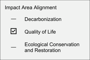
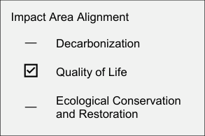
LEED v5 has been developed around three central areas of impact:
-
Decarbonization
-
Quality of Life
-
Ecological Conservation and Restoration
Every credit and prerequisite in LEED v5 are connected to decarbonization, quality of life, and/or ecological conservation and restoration, and this is annotated throughout the rating system, enabling project teams to easily shape and communicate their sustainability stories.
U.S. Green Building Council LEED v5 Reference Guide for Interior Design and Construction, April 2025 Launch Edition 2
PDF Page 14
BENEFITS OF USING LEED
LEED is designed to address environmental challenges while responding to the needs of a competitive market. LEED-certified buildings are designed to deliver many benefits, including:
-
Lower operating costs and increased asset value
-
Reduced waste sent to landfills
-
Energy and water conservation
-
Conserved and restored habitat for improved ecosystem function and biodiversity
-
Increased market transparency and expanded access to industry-leading green products and materials
-
More healthful and productive environments for occupants
-
Reductions in greenhouse gas (GHG) emissions
-
Qualification for tax rebates, zoning allowances, and other incentives in many cities
By participating in LEED, owners, operators, designers, and builders make a meaningful contribution to the green building industry. By documenting and tracking buildings’ resource use, they contribute to a growing body of knowledge that will advance research in this rapidly evolving field. This will allow future projects to build on the successes of today’s designs and bring innovations to the market.
GBCI independently verifies sustainability performance for LEED, ensuring the integrity of outcomes and strengthening market confidence in sustainability investment and innovation.
LEED CERTIFICATION PROCESS
A LEED project begins when the project team determines the scope, selects the appropriate rating system, confirms alignment with the minimum program requirements (MPRs), and registers the project on the Arc platform. The team designs the project to meet all prerequisites and the chosen credits, in coordination with their sustainability goals. The team compiles and submits the required documentation to GBCI for review. GBCI provides feedback on the documentation, offering the opportunity for project teams to make any needed design and construction changes or take additional steps to improve an existing project’s performance, and/or provide additional clarification needed for GBCI to determine compliance. Additional rounds of review follow, as needed and allowed, to earn certification of the project. For a more in-depth understanding of the certification process, see the Guides to Certification.
U.S. Green Building Council LEED v5 Reference Guide for Interior Design and Construction, April 2025 Launch Edition 3
PDF Page 15
GETTING STARTED
ABOUT THIS GUIDE
This guide explains the requirements of the LEED v5 Interior Design and Construction (ID+C) rating system, offering essential background information for contractors, engineers (mechanical, structural, and civil), architects, designers (interior and landscape), architects, designers, building operators, and LEED consultants. Early attention to rating system selection, minimum program requirements, and project boundaries ensure a smoother path to certification.
This guide is the first in a series of detailed resources for project teams pursuing LEED v5. It builds on the rating system requirements, providing background on each LEED category and a detailed explanation of the technical requirements for each credit.
WHAT’S INSIDE
This guide builds on the requirements listed in the rating system to provide background on each LEED category and an in-depth explanation of the technical requirements of each credit.
This guide contains:
-
LEED v5 rating system requirements
-
Rating system requirements explained
-
Documentation requirements
-
Referenced standards
As teams review each credit and prerequisite, they should carefully evaluate the options and pathways available, ensuring they align with the project’s specific goals, constraints, and characteristics.
When preparing documentation to submit for review, these materials may consist of contract documents (plans, specifications, elevations, sections, construction details, etc.) calculations, reports, manufacturer product information, photographs, and/or descriptive narratives.
The USGBC glossary is an additional resource: usgbc.org/glossary/v5
U.S. Green Building Council LEED v5 Reference Guide for Interior Design and Construction, April 2025 Launch Edition 4
PDF Page 16
CREDIT CATEGORIES
The prerequisites and credits within the LEED rating system are organized into eight categories, each addressing a fundamental aspect of sustainable, high-performance designs and construction practices:
-
Integrative Process, Planning, and Assessments (IP)
-
Location and Transportation (LT)
-
Sustainable Sites (SS)
-
Water Efficiency (WE)
-
Energy and Atmosphere (EA)
-
Materials and Resources (MR)
-
Indoor Environmental Quality (EQ)
-
Project Priorities (PR)
RATING SYSTEM SELECTION
LEED offers rating systems designed for specific project types. Projects must register under the most appropriate LEED rating system and use the guide appropriate to the project’s registration. In cases where the most appropriate rating system is unclear, additional guidance is provided in the USGBC Help Center: support.usgbc.org/hc/en-us. The project team may also raise a request to consult with GBCI: support.usgbc.org/hc/en-us/requests/new. The consultation should occur prior to registration to avoid the risk of GBCI determining, during the Preliminary Review, that an inappropriate rating system has been selected.
LEED FOR BUILDING DESIGN AND CONSTRUCTION (BD+C)
New Construction and Major Renovations Applicable to whole buildings, and whole additions to buildings, of various use types that are either new construction or undergoing major renovations and where at least 60% of the gross floor area is complete.
Major renovations are buildings with extensive interior alteration work in addition to work on the exterior shell of the building and/or primary structural components and/or the core and peripheral MEP (mechanical, electrical, plumbing) and service systems and/or site work. Typically, the extent and nature of the work prevent the primary function space from being used for its intended purpose while the work is in progress, and the project team must obtain a new certificate of occupancy before reoccupying the work area.
U.S. Green Building Council LEED v5 Reference Guide for Interior Design and Construction, April 2025 Launch Edition 5
PDF Page 17
Core and Shell Development Applicable to whole buildings of various use types that are either new construction or undergoing major renovations and at least 40% of the gross floor area is incomplete. Incomplete: does not have its basic floor, wall, and/or ceiling finishes installed, or essential mechanical, electrical, plumbing systems (or fixtures) necessary to occupy the space for its intended use, within the contracted scope of work.
LEED FOR INTERIOR DESIGN AND CONSTRUCTION (ID+C)
Commercial Interiors Applicable to interior renovation projects of commercial spaces (that have no scope for the exterior shell of the building and/or site work). The team installs movable furnishings, fixtures, and equipment (FF&E) to support the intended regular operations of the space.
LEED FOR BUILDING OPERATIONS AND MAINTENANCE (O+M)
Existing Buildings Applicable to existing buildings projects focused on operational improvement. This rating system focuses on whole buildings that have been fully operational and occupied for at least one year. Focusing on performance-driven strategies and outcomes allows buildings in use to achieve greater efficiency.
PROJECT TYPE REQUIREMENTS
The entire gross floor area of a LEED project must be certified under a single rating system (LEED BD+C: New Construction, LEED BD+C: Core and Shell, LEED ID+C: Commercial Interiors, or LEED O+M: Existing Buildings) and is subject to all prerequisites and attempted credits in that rating system, regardless of mixed construction or space usage type.
However, in some prerequisites and credits, there may be requirements identified for specific project types, such as schools, warehouse and distribution centers, healthcare, or residential.
Project type requirements must be met if 60% or more of the gross floor area of a project comprises that project type. For example, if a project is 75% residential and 25% retail, that project must follow the residential requirements in the rating system. In the Core and Shell rating system or in a new construction/major renovation project with incomplete space, the use type of the incomplete space must be based on the expected future use.
U.S. Green Building Council LEED v5 Reference Guide for Interior Design and Construction, April 2025 Launch Edition 6
PDF Page 18
PROJECTS WITH INCOMPLETE SPACE
Projects with incomplete space (future fit-out) may still pursue certification as long as the following criteria are met:
-
Incomplete space is less than 40% of the gross floor area.
-
Occupancy is counted for the incomplete space using projected values or, if unknown, the LEED default occupancy.
-
A letter of commitment from the owner is provided, attesting that the incomplete spaces will satisfy the requirements of each prerequisite and credit achieved by the project.
-
A description of the incomplete space is provided, identifying the scope that remains, the entity responsible for the remaining scope, and the reason the building is incomplete at the time of final application.
-
Prerequisite calculations must include the completed scope only. Credit calculations must include the completed and incomplete scopes, with the incomplete scope held equivalent to the baseline.
-
Contact USGBC prior to application submission for any attempted credits in which an adaptation for the incomplete space is not clear.
PROJECT OCCUPANCY
Occupancy counts for the project that will be used consistently throughout the application are important to establish early and share with the whole project team. Whenever possible, use actual or predicted occupancies. LEED requires occupancy to be assessed and reported for two groups: regular building occupants and visitors.
REGULAR BUILDING OCCUPANTS
Regular building occupants are routine users of a project (full- and part- time), such as:
-
Employees, daily volunteers, support staff (e.g., janitors)
-
Residents (e.g., dormitory, apartment, condo), overnight hotel guests, medical inpatients
-
K–12 students
VISITORS
Visitors are intermittent users of a project, such as:
- Retail customers
U.S. Green Building Council LEED v5 Reference Guide for Interior Design and Construction, April 2025 Launch Edition 7
PDF Page 19
-
Medical outpatients
-
Volunteers who only periodically use a building (e.g., once per week)
-
Higher-education classroom students
-
DEFAULT OCCUPANCY COUNTS
If the occupancy is unknown and cannot be reasonably projected, use one of the following resources to estimate occupancy:
-
Default occupant density from ASHRAE 62.1-2022, Table 6-1 [1]
-
Table 1. Default occupancy counts is based on gross floor area, excluding structured parking
Table 1. Default occupancy counts
| Col1 | Gross square feet per occupant | Col3 | Gross square meters per occupant | Col5 |
|---|---|---|---|---|
| Regular | Visitors | Regular | Visitors | |
| General office | 250 | 0 | 23 | 0 |
| Retail, restaurant | 435 | 95 | 40 | 9 |
| Retail, grocery store | 550 | 115 | 51 | 11 |
| Retail, general | 550 | 130 | 51 | 12 |
| Retail, service | 600 | 130 | 56 | 12 |
| Medical office | 225 | 330 | 21 | 31 |
| R&D or laboratory | 400 | 0 | 37 | 0 |
| Warehouse, distribution | 2,500 | 0 | 232 | 0 |
| Warehouse, storage | 20,000 | 0 | 1860 | 0 |
| Educational, day care | 630 | 105 | 59 | 10 |
| Educational, K–12 | 1,300 | 140 | 121 | 13 |
| Educational, postsecondary | 2,100 | 150 | 195 | 14 |
NOTE: For residential (i.e., apartment or condo), use the number of bedrooms in the dwelling unit plus one, multiplied by the number of such dwelling units.
NOTE: For a hotel or motel, use 1.5 occupants per guest room multiplied by the total number of guest rooms. Then multiply the resulting total by 60%.
AVERAGE VS. PEAK OCCUPANCY
In prerequisite/credit calculations, occupancy may be calculated in different ways:
1 “ASHRAE 62.1-2022”, ASHRAE, accessed March 31, 2025, https://www.ashrae.org/technical-resources/bookstore/standards-621-62-2.
U.S. Green Building Council LEED v5 Reference Guide for Interior Design and Construction, April 2025 Launch Edition 8
PDF Page 20
-
Daily average . The value representative of all the regular building occupants for a typical 24-hour day of operation. If numbers vary seasonally, use occupancy numbers that are a representative daily average over the entire operating season of the building.
- Peak total . The value representative of the highest number of occupants expected in the project at one time (e.g., shift overlap, events). Sometimes this value may be generated by the building code for fire safety, but a lower number can be used if justified.
If using default occupancy counts from Table 1, these must be used as the daily average and peak occupancy values.
Peak outpatients are the highest number of outpatients at a given point in a typical 24-hour period.
EQUIVALENCIES
The LEED rating system is written based on the most up-to-date and widely available standards. However, alternative standards or compliance paths may also be available to project teams. The Project Priority Library includes a list of equivalencies and alternative compliance paths available by credit, project type, or region.
If there is no guidance available allowing an equivalency or alternative compliance path, project teams may submit a request for USGBC to determine equivalency.
LEED PLATINUM REQUIREMENTS
LEED v5 has added specific requirements to advance decarbonization goals for achieving Platinum certification. In addition to earning all prerequisites and enough credits to reach the overall Platinum point threshold, all Platinum projects must achieve decarbonization requirements in the following credits:
LEED BD+C
-
EAc1 Electrification
-
EAc3 Enhanced Energy Efficiency
-
EAc4 Renewable Energy
-
MRc2 Reduce Embodied Carbon
LEED ID+C
-
EAc1 Electrification
-
EAc2 Enhanced Energy Efficiency
-
EAc3 Renewable Energy
U.S. Green Building Council LEED v5 Reference Guide for Interior Design and Construction, April 2025 Launch Edition 9
PDF Page 21
- MRc2 Assess and Reduce Embodied Carbon
LEED O+M
-
EAc1 GHG Emissions Reductions
-
EAc2 Optimized Energy Performance
-
EAc5 Decarbonization and Efficiency Plans
See Appendix I for the full list of LEED Platinum requirements.
U.S. Green Building Council LEED v5 Reference Guide for Interior Design and Construction, April 2025 Launch Edition 10
PDF Page 22
MINIMUM PROGRAM REQUIREMENTS (MPR)
The MPRs are the minimum characteristics or conditions that make a project appropriate to pursue LEED certification. These requirements are foundational to all LEED projects and define the types of buildings, spaces, and neighborhoods that the LEED rating system is designed to evaluate.
MPR 1. MUST BE IN A PERMANENT LOCATION ON EXISTING LAND
INTENT
The LEED rating system is designed to evaluate buildings, spaces, neighborhoods, communities, and cities in the context of their surroundings. A significant portion of LEED requirements depend on the project’s location; therefore, it is important that LEED projects are evaluated as permanent structures. Locating projects on existing land is crucial to avoiding artificial land masses that have the potential to displace and disrupt ecosystems.
REQUIREMENTS
All LEED projects must be constructed and operated on a permanent location on existing land. No project that is designed to move at any point in its lifetime may pursue LEED certification. This requirement applies to all land within the LEED project.
MPR 2. MUST USE REASONABLE LEED BOUNDARIES
INTENT
The LEED rating system is designed to evaluate buildings, spaces, neighborhoods, communities, cities, and all environmental impacts associated with those projects. Defining a reasonable LEED boundary ensures that a project is accurately evaluated.
REQUIREMENTS
The LEED project boundary must include all contiguous land associated with the project and that supports its typical operations. This includes land altered as a result of construction and features used primarily by the project’s occupants, such as hardscape (parking and sidewalks), septic or stormwater treatment equipment, and landscaping. The LEED boundary may not
U.S. Green Building Council LEED v5 Reference Guide for Interior Design and Construction, April 2025 Launch Edition 11
PDF Page 23
unreasonably exclude portions of the building, space, or site to give the project an advantage in complying with credit requirements. The LEED project must accurately communicate the scope of the certifying project in all promotional and descriptive materials and distinguish it from any non-certifying space.
MPR 3. MUST COMPLY WITH PROJECT SIZE REQUIREMENTS
INTENT
The LEED rating system is designed to evaluate buildings, spaces, or neighborhoods of a certain size. The LEED requirements do not accurately assess the performance of projects outside of these size requirements.
REQUIREMENTS
All LEED projects must meet the size requirements listed below.
LEED BD+C: New Construction and LEED O+M: Existing Buildings rating systems The LEED project must include a minimum of 1,000 square feet (93 square meters) of gross floor area.
LEED ID+C: Commercial Interiors rating systems The LEED project must include a minimum of 250 square feet (22 square meters) of gross floor area.
Further guidance on the MPRs can be found here: usgbc.org/credits?MinimumProgramRequirements
U.S. Green Building Council LEED v5 Reference Guide for Interior Design and Construction, April 2025 Launch Edition 12
PDF Page 24
RATING SYSTEM SCORECARDS
CREDIT CATEGORY VIEW
| Integrative Process, Planning, and Assessments (IP) IPp1 Climate Resilience Assessment | Col2 | Col3 | Col4 | 1 |
|---|---|---|---|---|
| Integrative Process, Planning, and Assessments (IP) IPp1 Climate Resilience Assessment | IPp1 | Climate Resilience Assessment | Climate Resilience Assessment | Required |
IPp2 | Human Impact Assessment | Human Impact Assessment | Required | |
IPp3 | Carbon Assessment | Carbon Assessment | Required | |
IPc1 | Integrative Design Process | Integrative Design Process | 1 | |
Location and Transportation (LT) | Location and Transportation (LT) | Location and Transportation (LT) | 14 | |
| LTc1 | Compact and Connected Development | Compact and Connected Development | 8 | |
LTc2 | Transportation Demand Management | Transportation Demand Management | 4 | |
LTc3 | Electric Vehicles | Electric Vehicles | 2 | |
Water Efficiency (WE) | Water Efficiency (WE) | Water Efficiency (WE) | 10 | |
| WEp1 | Minimum Water Efficiency | Minimum Water Efficiency | Required | |
WEc1 | Water Metering and Leak Detection | Water Metering and Leak Detection | 2 | |
WEc2 | Enhanced Water Efficiency | Enhanced Water Efficiency | 8 | |
Energy and Atmosphere (EA) | Energy and Atmosphere (EA) | Energy and Atmosphere (EA) | 31 | |
| EAp1 | Estimated Energy Use and Operational Carbon Projection | Estimated Energy Use and Operational Carbon Projection | Required | |
EAp2 | Minimum Energy Efficiency | Minimum Energy Efficiency | Required | |
EAp3 | Fundamental Commissioning | Fundamental Commissioning | Required | |
EAp4 | Energy Metering and Reporting | Energy Metering and Reporting | Required | |
EAp5 | Fundamental Refrigerant Management | Fundamental Refrigerant Management | Required | |
EAc1 | Electrification | Electrification | 5 | |
EAc2 | Enhanced Energy Efficiency | Enhanced Energy Efficiency | 12 | |
EAc3 | Renewable Energy | Renewable Energy | 5 | |
EAc4 | Enhanced Commissioning | Enhanced Commissioning | 4 | |
EAc5 | Grid Interactive | Grid Interactive | 3 | |
EAc6 | Enhanced Refrigerant Management 2 | Enhanced Refrigerant Management 2 | Enhanced Refrigerant Management 2 |
U.S. Green Building Council LEED v5 Reference Guide for Interior Design and Construction, April 2025 Launch Edition 13
PDF Page 25
| Col1 | Materials and Resources (MR) | Col3 | Col4 | 26 |
|---|---|---|---|---|
| MRp1 | Planning for Zero Waste Operations | Planning for Zero Waste Operations | Required | |
MRp2 | Quantify and Assess Embodied Carbon | Quantify and Assess Embodied Carbon | Required | |
MRc1 | Interior Materials Reuse | Interior Materials Reuse | 4 | |
MRc2 | Reduce Embodied Carbon | Reduce Embodied Carbon | 4 | |
MRc3 | Low-Emitting Materials | 4 | ||
MRc4 | Building Product Selection and Procurement | Building Product Selection and Procurement | 10 | |
MRc5 | Construction and Demolition Waste Diversion | Construction and Demolition Waste Diversion | 4 | |
Indoor Environmental Quality (EQ) | Indoor Environmental Quality (EQ) | Indoor Environmental Quality (EQ) | 18 | |
| EQp1 | Construction Management | Construction Management | Required | |
EQp2 | Fundamental Air Quality | Fundamental Air Quality | Required | |
EQp3 | No Smoking | No Smoking | Required | |
EQc1 | Enhanced Air Quality | Enhanced Air Quality | 2 | |
EQc2 | Occupant Experience | Occupant Experience | 7 | |
EQc3 | Accessibility and Inclusion | Accessibility and Inclusion | 2 | |
EQc4 | Resilient Spaces | Resilient Spaces | 3 | |
EQc5 | Air Quality Testing and Monitoring | Air Quality Testing and Monitoring | 4 | |
Project Priorities (PR) | Project Priorities (PR) | Project Priorities (PR) | 10 | |
| PRc1 | Project Priorities | Project Priorities | 9 | |
PRc2 | LEED AP | LEED AP | 1 | |
Total Possible Points 110 | Total Possible Points 110 | Total Possible Points 110 | Total Possible Points 110 |
U.S. Green Building Council LEED v5 Reference Guide for Interior Design and Construction, April 2025 Launch Edition 14
PDF Page 26
IMPACT AREA VIEWS
| Decarbonization | Col2 | Col3 |
|---|---|---|
| IP Prerequisite | Carbon Assessment | Required |
| IP Credit | Integrative Design Process | 1 |
| LT Credit | Compact and Connected Development | 8 |
| LT Credit | Transportation Demand Management | 4 |
| LT Credit | Electric Vehicles | 2 |
| WE Prerequisite | Minimum Water Efficiency | Required |
| WE Credit | Water Metering and Leak Detection | 2 |
| WE Credit | Enhanced Water Efficiency | 8 |
| EA Prerequisite | Estimated Energy Use and Operational Carbon Projection | Required |
| EA Prerequisite | Minimum Energy Efficiency | Required |
| EA Prerequisite | Fundamental Commissioning | Required |
| EA Prerequisite | Energy Metering and Reporting | Required |
| EA Prerequisite | Fundamental Refrigerant Management | Required |
| EA Credit | Electrification | 5 |
| EA Credit | Enhanced Energy Efficiency | 12 |
| EA Credit | Renewable Energy | 5 |
| EA Credit | Enhanced Commissioning | 4 |
| EA Credit | Grid Interactive | 3 |
| EA Credit | Enhanced Refrigerant Management | 2 |
| MR Prerequisite | Planning for Zero Waste Operations | Required |
| MR Prerequisite | Quantify and Assess Embodied Carbon | Required |
| MR Credit | Interior Materials Reuse | 4 |
| MR Credit | Reduce Embodied Carbon | 4 |
| MR Credit | Building Product Selection and Procurement | Building Product Selection and Procurement |
| MR Credit | MR Credit | MR Credit |
U.S. Green Building Council LEED v5 Reference Guide for Interior Design and Construction, April 2025 Launch Edition 15
PDF Page 27
| Quality of life | Col2 |
|---|---|
| IP Prerequisite | Climate Resilience Assessment Required Human Impact Assessment Required Integrative Design Process 1 Compact and Connected Development 8 Transportation Demand Management 4 Water Metering and Leak Detection 2 Low Emitting Materials 4 Building Product Selection and Procurement 10 Construction Management Required Fundamental Air Quality Required No Smoking Required Enhanced Air Quality 2 Occupant Experience 7 Accessibility and Inclusion 2 Resilient Spaces 3 Air Quality Testing and Monitoring 4 |
| IP Prerequisite | IP Prerequisite |
| IP Credit | IP Credit |
| LT Credit | LT Credit |
| LT Credit | LT Credit |
| WE Credit | WE Credit |
| MR Credit | MR Credit |
| MR Credit | MR Credit |
| EQ Prerequisite | EQ Prerequisite |
| EQ Prerequisite | EQ Prerequisite |
| EQ Prerequisite | EQ Prerequisite |
| EQ Credit | EQ Credit |
| EQ Credit | EQ Credit |
| EQ Credit | EQ Credit |
| EQ Credit | EQ Credit |
| EQ Credit | EQ Credit |
| Ecological conservation and restoration | Col2 | Col3 |
|---|---|---|
| IP Credit | Integrative Design Process 1 Compact and Connected Development 8 | Integrative Design Process 1 Compact and Connected Development 8 |
| LT Credit | LT Credit | LT Credit |
| WE Prerequisite | Minimum Water Efficiency | Required |
| WE Credit | Water Metering and Leak Detection | 2 |
| WE Credit | Enhanced Water Efficiency | 8 |
| MR Prerequisite | Planning for Zero Waste Operations | Required |
| MR Credit | Interior Materials Reuse | 4 |
| MR Credit | Building Product Selection and Procurement | 10 |
| MR Credit | Construction and Demolition Waste Diversion | 4 |
| EQ Prerequisite | No Smoking | Required |
U.S. Green Building Council LEED v5 Reference Guide for Interior Design and Construction, April 2025 Launch Edition 16
PDF Page 28
INTEGRATIVE PROCESS, PLANNING, AND ASSESSMENTS (IP)
OVERVIEW
As an industry, the built environment has evolved to prioritize whole-building performance over isolated systems. The Integrative Process, Planning, and Assessments (IP) category builds on this approach in LEED v5 by emphasizing the importance of early-stage interdisciplinary collaboration and holistic, iterative planning to arrive at interrelated systems. By utilizing systems thinking to identify synergies across building systems before design begins, the IP category ensures intentional alignment between tenant-level and building-level goals, with a focus on decisions under tenant control in commercial interiors projects.
This holistic approach promotes proactive consideration of how each project addresses decarbonization; quality of life, including social equity and resilience; and ecosystem conservation and restoration from the outset. The strategies within the IP category help shape projects that are environmentally responsible, resilient, and equitable, benefiting both occupants and the broader community.
Key aspects of this category include:
-
Timing . Initiating analysis in the early stages of the project (predesign)
-
Engagement . Ensuring the right people are involved
-
Interdisciplinary collaboration . Leveraging synergies across credit categories to maximize efficiencies and inform decision-making
-
Assessment-based understanding . Conducting discovery that provides insights into natural hazards, carbon emissions, and human impacts, which are referenced throughout the rating system
Decarbonization The built environment contributes significantly to global greenhouse gas (GHG) emissions, accounting for 21% of total GHG emissions and 31% of global carbon emissions in 2019. [2] The IP category’s 10-year carbon assessment addresses energy use, refrigerants, embodied carbon, and transportation impacts ( IPp3: Carbon Assessment ). This assessment promotes carbon literacy and equips project teams with knowledge to apply to future projects, fostering industry-wide progress.
2 “Chapter 9: Buildings”, IPCC, accessed March 31, 2025, https://www.ipcc.ch/report/ar6/wg3/chapter/chapter-9/.
U.S. Green Building Council LEED v5 Reference Guide for Interior Design and Construction, April 2025 Launch Edition 17
PDF Page 29
This assessment incorporates data from other sections of the rating system to support consistent and meaningful carbon reduction (e.g., MRp2: Quantify and Assess Embodied Carbon, MRc2: Reduce Embodied Carbon, MRc4: Building Product Selection and Procurement ).
Quality of life Environmental justice and other similar movements have brought the importance of understanding a community’s social context to the forefront. Additionally, practitioners are placing greater emphasis on prioritizing the health, safety, and welfare of building occupants. The American Institute of Architects Code of Ethics and Professional Conduct outlines their view of the obligation of designers, stating: “Members should employ their professional knowledge and skill to design buildings and spaces that will enhance and facilitate human dignity and the health, safety, and welfare of the individual and the public.” [3] The IP category addresses social equity by requiring an understanding of the local community, workforce, and supply chain, which encourages teams to confront inequities and positively impact their communities ( IPp2: Human Impact Assessment ).
Resilience across systems is a key topic throughout the LEED ID+C: Commercial Interiors rating system. Munich Re reported that global disaster losses in 2023 totaled $250 billion, highlighting the significant financial impact of natural disasters worldwide. [4] The required assessment of observed, projected, and future natural hazards for climate resilience aims to enhance awareness, increase transparency, reduce vulnerabilities, and ensure long-term safety and sustainability ( IPp1: Climate Resilience Assessment ).
Ecological conservation and restoration With a focus on ensuring the applicable expertise is in the room at the earliest stages (predesign), the IP category specifically calls out identifying and working toward ecosystemrelated goals ( IPc1: Integrative Design Process ). Projects may achieve this by integrating site hydrology analysis, native plant restoration, and soil health assessments to inform design decisions that mitigate habitat disruption and improve ecosystem services.
This approach encourages project teams to assess site conditions holistically, incorporating strategies that enhance biodiversity, protect natural resources, and support long-term ecological resilience.
By fostering early collaboration, holistic assessments, and interdisciplinary planning, the IP
category helps project teams develop the foundation for resilient, equitable, and environmentally
3 “Design for Human Dignity and the Health, Safety, and Welfare of the Public”, AIA Code of Ethics and Professional Conduct, Canon 1, ES1.5, accessed March 31, 2025, https://www.aia.org/code-ethics-professional-conduct. 4 “Uncounted Costs - Data Gaps Hide the True Human Impacts of Disasters in 2023.” 2024, UNDRR, January 17, 2024, accessed March 31, 2025, https://www.undrr.org/explainer/uncounted-costs-of-disasters-2023.
U.S. Green Building Council LEED v5 Reference Guide for Interior Design and Construction, April 2025 Launch Edition 18
PDF Page 30
responsible buildings. These strategies ensure that projects not only meet immediate performance goals, but also contribute to a sustainable, long-term future for both people and the planet.
U.S. Green Building Council LEED v5 Reference Guide for Interior Design and Construction, April 2025 Launch Edition 19
PDF Page 31
Integrative Process, Planning and Assessments Prerequisite
CLIMATE RESILIENCE ASSESSMENT
IPp1
REQUIRED
INTENT
To promote comprehensive assessment of observed, projected, and future natural hazards for climate resilience, aiming to increase awareness of hazards, increase transparency of risks, reduce vulnerabilities, and ensure long-term safety and sustainability.
REQUIREMENTS
| Achievement pathways | Points |
|---|---|
Commercial Interiors | N/A |
Climate and Natural Hazard Assessment |
Complete a climate and natural hazard assessment.
As part of the assessment, identify observed, projected, and future natural hazards that could potentially affect the project site and building function. Address site-specific natural hazards, including, but not limited to, drought, extreme heat, extreme cold, flooding, hurricanes and high winds, hail, landslides, sea level rise and storm surge, tornadoes, tsunamis, wildfires and smoke, winter storms, and other relevant hazards.
Identify two priority hazards, at minimum, to address through proposed design strategies. For each priority hazard, the project team must assess and specify the following:
-
Intergovernmental Panel on Climate Change (IPCC) emissions scenario used, specifying the shared socioeconomic pathways
-
Projected service life of the LEED project (e.g., fiscal year 2050 or 100 years)
-
Hazard level
-
Hazard risk rating
-
Exposure, sensitivity, adaptive capacity, vulnerability, and overall risk levels
-
Potential impact on the project site and building function
-
Potential impact on the project site during construction
Where possible, use the information from the assessment to inform the planning, design, and operations and maintenance of the project and describe how project-specific strategies were considered.
U.S. Green Building Council LEED v5 Reference Guide for Interior Design and Construction, April 2025 Launch Edition 20
PDF Page 32
REQUIREMENTS EXPLAINED
Incorporating climate resilience into the design and development of interior spaces helps mitigate the impacts of climate change and enhances the long-term durability of building interiors against key vulnerabilities. A climate resilience assessment supports project teams in identifying and evaluating building-specific climate hazards that could threaten the performance, safety, and longevity of interior spaces and systems. This process provides a framework for embedding data-driven, forward-looking strategies that align with regional climate adaptation plans, building codes, and sustainability objectives while addressing the unique considerations of interior environments.
Addressing climate risks during interior design and construction improves the ability of building systems, occupant well-being, and operational continuity to withstand extreme weather events and climate stressors. These strategies also support broader goals of public safety, economic stability, and community resilience by reducing disruptions to interior spaces. In proactively integrating these considerations, projects following LEED ID+C: Commercial Interiors guidelines can adapt to changing conditions, ensure long-term functionality, and reduce life cycle costs while creating more sustainable and resilient interior environments.
This prerequisite entails project teams conducting a comprehensive climate and natural hazard assessment, including identifying current and projected hazards that may impact the project site and building operations. The assessment must address site-specific hazards such as drought, heat, flooding, hurricanes, wildfires, and other relevant risks. Teams must prioritize at least two hazards and analyze them using the IPCC Shared Socioeconomic Pathways (SSP) emissions scenarios [5], specifying the project’s service life and assessing hazard levels, risks, vulnerability, and potential impacts on-site operations and construction. In alignment with the critical need for designers to design for the safety and welfare of occupants, the findings should be used to inform the project’s planning, design, operations, and maintenance.
Climate and Natural Hazard Risk Assessment for Interior Spaces
This prerequisite entails project teams conducting a climate and natural hazard assessment to identify current and projected hazards that may impact the interior environment and its critical systems. The assessment must address hazards such as drought, heat, flooding, hurricanes, wildfires, and other relevant risks that could disrupt building operations, occupant safety, and interior functionality.
Unlike whole-building assessments in LEED BD+C, the resilience of interior systems and spaces within the larger building context is what projects using LEED ID+C: Commercial
5 “Intergovernmental Panel on Climate Change, Working Group I, Sixth Assessment Report”, IPCC, accessed March 31, 2025, https://interactive-atlas.ipcc.ch/.
U.S. Green Building Council LEED v5 Reference Guide for Interior Design and Construction, April 2025 Launch Edition 21
PDF Page 33
Interiors should focus on. Teams must determine how climate hazards could affect indoor air quality, heating ventilation and air conditioning (HVAC) efficiency, electrical systems, material durability, and occupant well-being. The assessment should analyze at least two priority hazards using IPCC SSP emissions scenarios, defining the project’s expected service life and assessing hazard levels, risks, vulnerabilities, and potential operational impacts.
Since LEED ID+C: Commercial Interiors projects operate within existing structures, the assessment should also consider how building-wide resilience strategies (or lack thereof) influence interior spaces. For instance, if a building is in a flood-prone area, interior projects may need to incorporate moisture-resistant materials, elevated critical systems, and emergency response protocols for water damage mitigation. If extreme heat is a priority hazard, the assessment should evaluate HVAC performance, thermal comfort strategies, and interior materials’ heat resistance.
Identification of Priority Hazards
Project teams must identify at least two priority hazards based on the assessment, considering historical hazard data, projected future risks, and the impact on interior environments and systems. The assessment should integrate regional climate models, hazard mitigation plans, and available climate risk databases to determine the likelihood and severity of each hazard.
For LEED ID+C: Commercial Interiors projects, priority hazards should be identified based on their potential to disrupt building operations, occupant safety, and interior system performance. Teams should consider factors such as the resilience of mechanical, electrical, and plumbing systems, as well as indoor temperature stability, air quality, and material durability.
To support this evaluation, project teams can use tools such as the FEMA National Risk Index [6] , NOAA Climate Explorer [7], or municipal hazard mitigation plans to understand site-specific risks. For example, if a commercial interior project is in an area experiencing increasing extreme heat events, priority hazards may include excessive indoor temperatures and strain on HVAC systems. If the project is located in a coastal region vulnerable to storm surge, teams may prioritize flood-related risks that could impact electrical and IT infrastructure within the interior space.
Once priority hazards are identified, teams must document findings in the climate resilience assessment template or submit an equivalent external assessment tool. This ensures that climate risks are systematically analyzed and addressed within the scope of interior design and operations.
6 “FEMA National Risk Index”, FEMA, accessed March 31, 2025, https://hazards.fema.gov/nri/. 7 “NOAA Climate Explorer”, NOAA, accessed March 31, 2025, https://crt-climate-explorer.nemac.org/.
U.S. Green Building Council LEED v5 Reference Guide for Interior Design and Construction, April 2025 Launch Edition 22
PDF Page 34
Assessing Hazards
After project teams identify two priority hazards, they must evaluate the impact by specifying the IPCC emissions scenario [8] used in the assessment, which outlines possible future atmospheric GHG concentrations. Teams should define scenarios that are both acceptable and appropriate for the project’s geographic location, taking into account local climate action plans to guide their selection. For instance, SSP 1-2.6 (Low-Emissions Scenario) is recommended for projects aiming to align with ambitious global climate mitigation goals or for those with shorter expected life spans (20 - 30 years), where less severe climate impacts are expected. Conversely, SSP 5- 8.5 (High Emissions Scenario) is more suitable for projects in high-risk areas, those with longer life spans (50+ years), or projects where significant climate impacts are anticipated due to limited mitigation measures or regional vulnerabilities.
Next, teams must define the projected service life of the project. For LEED projects, the projected service life refers to the project’s expected life span, which could extend to fiscal year 2050 or up to 100 years, during which the assessment of hazard risks remains applicable. Project teams must also evaluate the hazard level and assign a hazard risk rating based on the potential severity and impact. The hazard level reflects the intensity of a specific hazard event, categorized as low, medium, or high. Project teams should report and identify the level of each potential hazard using historical data and future projections. Teams can refer to the IPCC climate projections for historical data or climate projections. The hazard risk rating typically comes from local or regional hazard mitigation plans, and it assesses the likelihood of a hazard occurring. Teams must provide a risk rating for each identified hazard.
Project teams must evaluate the project’s susceptibility to each hazard and consider multiple factors, including exposure, sensitivity, adaptive capacity , vulnerability , and overall risk levels. Exposure refers to the degree to which the project is vulnerable to hazards, such as its proximity to water bodies or seismic zones. Sensitivity indicates how significantly these hazards may affect the project, based on factors like materials, structural design, and infrastructure. Adaptive capacity refers to the project’s ability to adapt, withstand, or recover from the impacts of hazards through resilient design, contingency planning, or technology. A project with backup generators and multiple water supply systems has a higher adaptive capacity compared to one without.
Vulnerability reflects the project’s overall susceptibility, considering both its sensitivity and adaptive capacity. The overall risk level is a combined assessment of hazard severity, exposure, sensitivity, adaptive capacity, and vulnerability, categorized as low, medium, or high.
Teams must assess the potential impacts of each hazard on the project. Project hazards can disrupt essential services, damage structures, cause long-term operational challenges, and
8 “Intergovernmental Panel on Climate Change, Working Group I, Sixth Assessment Report,” IPCC, https://interactive-atlas.ipcc.ch/.
U.S. Green Building Council LEED v5 Reference Guide for Interior Design and Construction, April 2025 Launch Edition 23
PDF Page 35
impact project’s operational aspects. During the operations phase, the assessment must consider the impact of these hazards on facility management, occupant safety, and service continuity. This includes potential disruptions to building systems, energy and water supply reliability, indoor environmental quality, emergency preparedness, workforce safety, and the long-term performance of structural and mechanical components. Hazards may also affect maintenance schedules, operational costs, and the ability to provide critical services during extreme weather events.
Hazard Assessment for Interior Environments
Teams must define the anticipated service life of the interior project, which often corresponds to lease terms, expected tenant occupancy, or the life span of major interior systems and finishes. While whole-building service life may extend beyond 50 years, interior spaces typically undergo renovation or reconfiguration every 10 - 30 years, requiring resilience strategies that support both short-term adaptability and long-term sustainability.
Project teams must analyze how hazards may affect interior operations, including temperature fluctuations, humidity control, indoor air quality, occupant safety, and potential damage to furniture, finishes, and equipment.
Integration into Interior Project Planning and Interior Design
As part of the climate resilience assessment, project teams must use findings from the hazard assessment to inform interior planning, design, operations, and maintenance strategies. Unlike whole-building projects, LEED ID+C: Commercial Interiors projects must evaluate how climate hazards affect interior environments, including occupant comfort, material durability, indoor air quality, and system performance.
During the planning and design phase, teams should focus on resilient interior design strategies that enhance thermal comfort, air quality, moisture control, and operational efficiency. For example, if flooding is identified as a priority hazard, strategies may include selecting waterresistant flooring and wall finishes, elevating electrical and IT infrastructure, and incorporating dehumidification systems to mitigate post-flood moisture buildup. If extreme heat is a concern, teams should optimize HVAC zoning and controls, incorporate passive cooling strategies such as operable windows, and specify materials with high thermal resistance.
Where possible, resilience considerations should be embedded into material and system selection, lighting strategies, and space planning to ensure interiors remain adaptable to changing climate conditions and operational demands. Incorporating risk-informed strategies early in the interior fit-out process allows teams to proactively address vulnerabilities, extend the life span of finishes and equipment, and ensure long-term occupant safety and well-being.
U.S. Green Building Council LEED v5 Reference Guide for Interior Design and Construction, April 2025 Launch Edition 24
PDF Page 36
Identifying site-specific hazards and vulnerabilities enables the development of interior-focused resilience solutions, minimizing disruptions and increasing asset longevity in the face of extreme climate events.
LEED ID+C: Commercial Interiors projects integrating resilient interior planning, durable material choices, and climate-adaptive operational strategies, can enhance building performance, occupant health, and long-term usability. Proactive climate resilience planning allows for interior spaces to adapt effectively to evolving threats, preserving functionality, safety, and efficiency throughout their life span.
DOCUMENTATION
| Project types | Options | Paths | Documentation |
|---|---|---|---|
All | All | All | The project’s climate and natural hazard assessment (using the USGBC Climate Resilience Assessment Template or equivalent). |
REFERENCED STANDARDS
-
Intergovernmental Panel on Climate Change, Working Group I, Sixth Assessment Report (interactive-atlas.ipcc.ch)
U.S. Green Building Council LEED v5 Reference Guide for Interior Design and Construction, April 2025 Launch Edition 25
PDF Page 37
Integrative Process, Planning and Assessments Prerequisite
HUMAN IMPACT ASSESSMENT
IPp2
REQUIRED
INTENT
To ensure that project development is guided by a thorough understanding of the social context of the local community, workforce, and supply chain, helping to address potential social inequities.
REQUIREMENTS
| Achievement pathways | Points |
|---|---|
Commercial Interiors | N/A |
Human Impact Assessment |
Complete a human impact assessment that draws on relevant information from the following four specified categories, as applicable:
-
Demographics : These may include race and ethnicity, gender, age, income, employment rate, population density, education levels, household types, and identification of nearby vulnerable populations.
-
Local infrastructure and land use : This may include adjacent transportation and pedestrian infrastructure, adjacent diverse uses, relevant local or regional sustainability goals/commitments, and applicable accessibility code(s).
-
Human use and health impacts : These may include housing affordability and availability, availability of social services (e.g., healthcare, education, social support networks), community safety, local community groups, and supply chain and construction workforce protections.
-
Occupant experience : This may include opportunities for daylight, views, and operable windows; environmental conditions of air and water; and adjacent soundscapes, lighting, and wind patterns within the context of surrounding buildings (microclimate, solar scape, and neighboring structures).
-
Other: (specify)
Where possible, use the information from the assessment to inform the planning, design, and operations and maintenance of the project and describe how project-specific strategies were considered.
U.S. Green Building Council LEED v5 Reference Guide for Interior Design and Construction, April 2025 Launch Edition 26
PDF Page 38
REQUIREMENTS EXPLAINED
This prerequisite requires that the project team comprehensively evaluate and understand the social, economic, and environmental context of the local community, workforce, and supply chain before developing the project. Teams will gather and analyze this understanding through methods such as site analysis, community outreach, census reports, GIS mapping, and partnerships with local organizations to ensure the project aligns with community needs and promotes equitable outcomes. Teams must select key characteristics to evaluate within the categories of demographics, local infrastructure and land use, human use and health impacts, and occupant experience. These analyses and findings should go on to inform the project’s planning, design, operations, and maintenance strategies.
Ultimately, this assessment balances environmental goals with the needs and aspirations of the people affected, fostering projects that are both ecologically and socially responsible. It supports frameworks for how designers ensure the health, safety, and welfare of those they design for. This will be an educational process for teams, especially for those who have not conducted similar assessments previously. With intentional planning, teams can integrate project-specific strategies by identifying potential disparities and work collectively toward creating a more inclusive and equitable community.
Human Impact Assessment
A Human Impact Assessment is a process in which quantitative and qualitative data for a proposed project is collected through identifying characteristics unique to the project site and its surrounding community. It requires projects to understand the sociopolitical context of the site, such as the cultural makeup of neighboring residents or average income rates. Additionally, it asks projects to identify relevant infrastructure and policy, such as zoning restrictions or accessibility codes. The assessment also requires taking stock of what resources may be accessible to the residents or potential end users, such as transit availability or healthcare. Last, it evaluates impacts on occupant experience, such as air and water quality. Project teams must consider how these elements interact with and impact one another to ensure that they guide project development with a comprehensive understanding of its social context.
Defining community Project teams must first establish the scope of their assessment by identifying the community. Communities have both geographic and functional definitions. Geographic communities start with the project’s neighborhood — the people who live and work in and near the project and interact with it by proximity. Geographic communities can also extend beyond to include towns, cities, or counties. Functional communities include all occupants, construction workers, and visitors who come to the building. These people may or may not live nearby. Teams can also define community through various affinities or commonalities, such as age, ethnicity, income
U.S. Green Building Council LEED v5 Reference Guide for Interior Design and Construction, April 2025 Launch Edition 27
PDF Page 39
level, housing status, or educational background. The community may extend to include project team members such as architects, engineers, contractors, and designers who oversee the planning, design, and construction phases. Community within the context of the supply chain includes material suppliers, manufacturers, and distributors, along with the workforce involved in production and transportation, highlighting local engagement and fair labor practices.
Address the core categories of human impact Teams must complete a thorough assessment that evaluates the potential impact of the project on people, including living conditions, health, food security, education, and access to other resources. The assessment must include data collection and analysis of core human impact categories such as demographic, infrastructure, health, and occupant experience factors, as well as any other relevant social impacts identified, providing a comprehensive overview of the human impacts of project development.
Project teams should engage with community members and other relevant groups to gather insights, understand local needs, and validate data.
-
Demographics . The first category evaluates the local demographics of the area surrounding the project site, which is critical to understanding how the design may influence the social fabric of the surrounding community. This process involves analyzing key demographic characteristics, including factors such as race and ethnicity, gender, age distribution, income levels, employment rates, population density, education levels, and household types. Additionally, it includes identification of nearby vulnerable populations to consider how their needs can be addressed in the project’s development. Teams are suggested to collaborate with nonprofit organizations that work directly with the people of the community.
-
Local infrastructure and land use . The second category examines the project’s impact on local infrastructure and land use, as well as identifying existing infrastructure that provides an opportunity to connect to the project. Teams must assess the adjacent public transit systems such as walkways, bike lanes, and road networks to ensure the project integrates well with existing mobility options and promotes sustainable transportation. The evaluation requires an analysis of diverse land uses in the vicinity, such as residential, commercial, industrial, and recreational spaces, to determine how the project might influence the functional balance of the area.
The assessment encourages reviewing the local community’s sustainability commitments, such as city-wide goals to reduce GHG emissions or promote energy efficiency, highlighting that the project can support broader efforts to create a more sustainable future. Identifying and complying with relevant accessibility codes and standards is another key aspect of the assessment to strengthen the project’s
U.S. Green Building Council LEED v5 Reference Guide for Interior Design and Construction, April 2025 Launch Edition 28
PDF Page 40
adherence to legal requirements regarding access for people with disabilities, while following best practices for creating inclusive, barrier-free environments.
- Human use and health impacts . The third category evaluates the project’s effects on human use and its impact on public health and well-being. This involves a thorough assessment of the community’s current access to essential resources, as well as the overall quality of life for residents. It is important to assess whether the project will address or alleviate these challenges, particularly regarding the availability of affordable housing. The assessment must also analyze the community’s access to social services, such as healthcare, education, and social support networks.
Community safety is another important factor to public health and well-being. Projects that incorporate features such as public spaces, adequate lighting, and pedestrianfriendly designs can foster a sense of safety and belonging. Projects must also consider the protections and working conditions for the local supply chain and construction workforce to ensure ethical practices and fair treatment. Within the scope of reason, this includes prioritizing local procurement and employment to support the local economy, providing fair wages and benefits to workers, establishing safe jobsite conditions, and implementing transparent labor practices to prevent exploitation and unjust treatment.
-
Occupant experience . The fourth category considers the project’s influence on the overall occupant experience. The goal is to thoroughly examine how the design and construction of the project can influence the health, comfort, and well-being of its occupants. This includes an analysis of key environmental factors such as the availability of natural daylight, the quality and orientation of views, and the opportunity to provide operable windows for fresh air circulation, as well as air and water quality. Additionally, it considers how external elements - such as the surrounding soundscapes, the quality of artificial and natural lighting, and the impact of wind patterns on the building and adjacent structures - affect the indoor environment and the overall experience of those inhabiting the space. This assessment encourages the project to create a positive and health-conscious environment for its occupants.
-
Other . Project teams may include any additional relevant social factors that are evaluated as part of the Human Impact Assessment.
Integration into Project Planning and Design
Project teams should use the findings from the Human Impact Assessment to inform the project’s planning, design, operations, and maintenance phases. Things to consider include how the identified social factors inform project-specific decisions, such as changes to design features, operational practices, or community engagement strategies. Project teams can
U.S. Green Building Council LEED v5 Reference Guide for Interior Design and Construction, April 2025 Launch Edition 29
PDF Page 41
implement strategies that promote inclusivity, fair labor practices, and equitable access to opportunities. This supports the community’s economic and social well-being and helps create a more resilient and sustainable project outcome. This integration is a tool to drive meaningful change within the design as well as at the community level.
DOCUMENTATION
| Project types | Options | Paths | Documentation |
|---|---|---|---|
All | All | All | The project’s human impact assessment (using the USGBC Human Impact Assessment Template or equivalent). |
REFERENCED STANDARDS
- None
U.S. Green Building Council LEED v5 Reference Guide for Interior Design and Construction, April 2025 Launch Edition 30
PDF Page 42
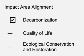
Integrative Process, Planning and Assessments Prerequisite
CARBON ASSESSMENT
IPp3
REQUIRED
INTENT
To understand and reduce long-term direct and indirect carbon emissions, including on-site combustion, grid-supplied electricity, refrigerants, and embodied carbon.
REQUIREMENTS
| Achievement pathways | Points |
|---|---|
Commercial Interiors | N/A |
Carbon Assessment |
USGBC will provide the project team with a 10-year projected carbon assessment for the project. The assessment will use data from the following:
-
EAp1: Estimated Energy Use and Operational Carbon Projection
-
EAp5: Fundamental Refrigerant Management
-
MRp2: Quantify and Assess Embodied Carbon
-
LTc2: Transportation Demand Management (optional)
REQUIREMENTS EXPLAINED
This prerequisite requires a 10-year carbon assessment of all emissions within the project boundary but does not require any additional data to be entered beyond what is already required by the three related prerequisites and the optional credit, if pursued.
Until recently, most projects only considered GHG emissions from operational energy use, if emissions were considered at all. However, as it has become increasingly clear that emissions from construction (“embodied carbon”) and refrigerants can also be quite considerable, LEED v5 has introduced prerequisites to assess carbon emissions from all three sources. This unifying prerequisite enables project teams to compare their sources of emissions and see which are more or less significant. The integrative process prerequisite gathers data from the three related prerequisites ( EAp1: Estimated Energy Use and Operational Carbon Projection, EAp5: Fundamental Refrigerant Management, MRp2: Quantify and Assess Embodied Carbon ), and optionally from LTc2: Transportation Demand Management, if that credit has been pursued, and provides project teams with a report and visualization so that they can see how their different
U.S. Green Building Council LEED v5 Reference Guide for Interior Design and Construction, April 2025 Launch Edition 31
PDF Page 43
sources of emissions will compare over a 10-year time horizon, to enable better decisionmaking about carbon.
Carbon Assessment Supplied by USGBC
From the data in the three prerequisites and the optional credit, USGBC will develop a 10-year carbon assessment of the estimated emissions from energy use, refrigerants, embodied carbon, and, for some projects, transportation. It includes:
-
Annual carbon emissions from each source for 10 years
-
Cumulative emissions from each source each year for 10 years
-
Cumulative emissions over 10 years in total and from each source and the percentage of the total from each source
Additional considerations The information in this carbon assessment provides an overview of the various sources of carbon emissions and helps tenants make informed decisions to reduce the project’s emissions. Although not required for compliance, sharing the 10-year carbon projection with additional parties, including the landlord, can benefit. Landlords may find value in this information and develop a way of measuring and reporting emissions from the whole building or other projects within their portfolio.
This prerequisite does not require comprehensive carbon accounting, wholebuilding life cycle analyses (WBLCA), or “whole-interiors” LCA, nor is it meant to substitute for more in-depth analysis. Instead, LEED v5 requires this basic crosscategorical carbon assessment to enable a broad understanding of how project emissions across sources will add up over time, using data that all LEED v5 projects must submit under other prerequisites and applying reasonable assumptions.
Assumptions Behind the Assessment
While project teams do not need to compile any calculations to complete this credit, the following section outlines the assumptions behind the USGBC-supplied carbon assessment for full transparency. Project teams should conduct their own analysis in addition to this Carbon Assessment if more customized results are desired.
U.S. Green Building Council LEED v5 Reference Guide for Interior Design and Construction, April 2025 Launch Edition 32
PDF Page 44
Analysis Period Tenant spaces are assumed to be renovated every 10 years on average; thus, the LEED ID+C: Commercial Interiors carbon assessment uses a 10-year period for the analysis.
Operational Carbon Emissions EAp1: Estimated Energy Use and Operational Carbon Projection calculates the business-asusual (BAU) carbon projection from operational emissions from energy over 10 years. The BAU assumes that emissions from fuel use will remain constant, and that emissions from electricity will decline linearly at 3.8% per year (the equivalent of declining by 95% over 25 years). See EAp1: Estimated Energy Use and Operational Carbon Projection for more information.
Refrigerant Emissions EAp5: Fundamental Refrigerant Management calculates the annual refrigerant emissions. It uses a default annual leakage rate of 2%, or an annual leakage rate of 1% for projects pursuing Option 2. Limit Refrigerant Leakage of EAc6: Enhanced Refrigerant Management .
Embodied Carbon Emissions MRp2: Quantify and Assess Embodied Carbon calculates the embodied carbon in global warming potential (GWP) (kgCO2e) of the project interiors. Assumptions required to calculate the embodied carbon are found in MRp2: Quantify and Assess Embodied Carbon.
A1-A3 embodied carbon emissions result from multiplying the MRp2: Quantify and Assess Embodied Carbon embodied carbon values by 1.5 for interiors and MEP products, A4, and A5 emissions. Recurring embodied carbon assumes the project undergoes renovations every 10 years. Multiply the MRp2: Quantify and Assess Embodied Carbon embodied carbon values by 0.25 to account for the recurring embodied carbon.
Transportation Emissions Teams may only calculate the emissions projection from transportation when the project pursues LTc2: Transportation Demand Management. The projections assume no change in vehicle miles traveled (VMT) over the 10-year period and a linear 95% grid decarbonization.
U.S. Green Building Council LEED v5 Reference Guide for Interior Design and Construction, April 2025 Launch Edition 33
PDF Page 45
DOCUMENTATION
| Project types | Options | Paths | Documentation |
|---|---|---|---|
All | All | All | Completed documentation of_EAp1: Estimated Energy Use_ and Operational Carbon Projection, EAp5: Fundamental Refrigerant Management,_ MRp2: Quantify and Assess_ Embodied Carbon, and if attempted_ LTc2: Transportation_ Demand Management. |
REFERENCED STANDARDS
- None
U.S. Green Building Council LEED v5 Reference Guide for Interior Design and Construction, April 2025 Launch Edition 34
PDF Page 46
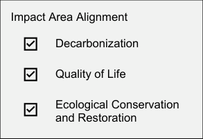
Integrative Process, Planning and Assessments Credit
INTEGRATIVE DESIGN PROCESS
IPc1
1 point
INTENT
To support high-performance, cost-effective, and cross-functional project outcomes through an early analysis and planning of the interrelationships among systems. To provide a holistic framework for project teams to collaboratively address decarbonization, quality of life, and ecosystem conservation and restoration across the entire LEED rating system.
REQUIREMENTS
| Achievement pathways | Points |
|---|---|
Commercial Interiors | 1 |
Integrative Design Process | 1 |
OR | |
LEED-certified Building | 1 |
Integrative Design Process
Beginning in predesign and continuing through early occupancy, identify and apply opportunities to achieve synergies across disciplines and building systems through the following initiatives:
-
Integrated team : Assemble and convene an interdisciplinary project team with diverse perspectives. Ensure the process is an equitable team effort through organized facilitation.
-
Design charrette : During predesign or early in design, conduct a charrette with the owner or owner’s representative and participants representing at least 4 key perspectives (e.g., architect, contractor, energy modeler, or community engagement representatives).
-
LEED goal-setting : Work as a team to define a set of specific and measurable project goals that address the LEED v5 impact areas of decarbonization, quality of life, and ecosystem conservation and restoration. Incorporate these goals into the owner’s project requirements (OPR).
OR
LEED-certified Building (1 point)
Locate the project in a LEED-certified building.
U.S. Green Building Council LEED v5 Reference Guide for Interior Design and Construction, April 2025 Launch Edition 35
PDF Page 47
REQUIREMENTS EXPLAINED
This credit requires a different approach to design than the conventional, linear architectural process. Conventionally, the design and construction disciplines work separately, and their solutions to design and construction challenges are fragmented. These “solutions” often create unintended consequences–some positive, but mostly negative. The corollary is that when areas of practice are integrated, it becomes possible to significantly improve building performance and achieve synergies that yield economic, environmental, and human health benefits.
Integrative Design Process (IDP)
In an IDP, an entire team–clients, designers, builders, and operators–identifies overlapping relationships, services, and redundancies among systems so that interdependencies and benefits that might otherwise go unnoticed can be explored, with the goal of increasing performance and reducing costs. To work this way requires that project teams, whose members represent various disciplines, come together so that the knowledge, analyses, and ideas from each discipline can inform and link with the systems and components of all other disciplines. In this way, LEED credits become aspects of a whole rather than separate components, and the entire design and construction team can identify the interrelationships and linked benefits across multiple LEED credits.
Approaching certification using an integrative process gives the project team the greatest chance of success. The process includes three phases:
-
Discovery . The most important phase of the integrative process, discovery expands what is conventionally called predesign. A project is unlikely to meet its environmental goals cost-effectively without this discrete phase. Discovery work should take place before schematic design begins.
-
Design and construction (implementation) . This phase begins with what is conventionally called schematic design. It resembles conventional practice but integrates all the work and collective understanding of system interactions reached during the discovery phase.
-
Occupancy, operations, and performance feedback . This phase focuses on preparing to measure performance and creating feedback mechanisms. Assessing performance against targets is critical for informing building operations and identifying the need for any corrective action.
Achieving economic and environmental performance requires bringing every issue and all essential voices - community, clients, designers, engineers, builders, and operators - into the project at the earliest point, before the team designs anything.
U.S. Green Building Council LEED v5 Reference Guide for Interior Design and Construction, April 2025 Launch Edition 36
PDF Page 48
This holistic process of research, analysis, and workshops follows an iterative cycle that refines the design solutions. In the best scenario, the research and workshops continue until the project team optimizes the systems, identifies all reasonable synergies, and documents and implements the related strategies associated with all LEED credits.
Integrated Team The first step involves assembling an interdisciplinary design team with relevant and impacted parties, including owners, building users, architects, engineers, contractors, and community representatives. Participants are to consider all project phases — from early design to construction and operations — to collaboratively set goals, refine strategies, and balance performance, feasibility, and costs.
During construction and procurement, contractors and builders provide insights on constructability, materials, and lifecycle impacts. During occupancy, collaboration ensures the team upholds design intent, implements energy strategies effectively, and monitors performance for continuous improvement.
Design Charrette The first charrette with interdisciplinary members is crucial for collective agreement on goals, priorities, and a shared project vision. Teams must proactively address major concerns early to avoid redesign delays and inefficiencies later in the project life cycle. Leveraging tools such as energy and daylight modeling, building information modeling, and lifecycle assessments ( LCA ) during the conceptual design phase ensures a data-driven approach to identifying conflicts and optimizing performance.
To foster engagement and collaboration, project teams must implement equitable processes by facilitating well-structured meetings, workshops, and charrettes. Resources such as the U.S. Department of Energy’s Handbook for Planning and Conducting Charrettes [9] provide practical checklists and agendas to guide these efforts.
LEED Goal-setting: Decarbonization, Quality of Life, and Ecosystem Conservation and Restoration Goals
Project teams must establish measurable goals aligned with LEED v5’s core impact areas: decarbonization, quality of life, and ecological conservation and restoration. It is an opportunity for project teams to further connect assessment findings to project outcomes. Clear metrics guide decisions, such as carbon reduction percentages, well-being outcomes, or ecosystem restoration targets.
9 “Handbook for Planning and Conducting Charettes”, U.S. Department of Energy, accessed March 31, 2025, https://www.nrel.gov/docs/fy09osti/44051.pdf.
U.S. Green Building Council LEED v5 Reference Guide for Interior Design and Construction, April 2025 Launch Edition 37
PDF Page 49
-
Decarbonization . Strategies include reducing operational and embodied carbon emissions. Teams can replace fossil fuel systems with renewable or electric solutions, upgrade to energy-efficient equipment, and specify low-carbon materials such as highperformance glazing and supplementary cementitious materials (SCMs ) in concrete.
-
Quality of life . A human-centered approach incorporates health, well-being, resilience, and equity into the design. Strategies such as inclusive design and biophilic design, connect occupants to nature, reduce stress, improve air quality, and enhance cognitive performance. Selecting nontoxic and hazard-resilient materials promotes healthier indoor environments, benefiting occupants’ physical and mental health as well as longterm sustainability.
-
Ecosystem conservation and restoration . Sustainable practices such as minimizing soil erosion, planting native vegetation, and integrating green infrastructure (e.g., permeable pavement, green roofs) reduce environmental impact and restore ecological functions.
-
Teams must utilize this thorough research and analysis during the pre-design phase to inform LEED documentation requirements, including the OPR, Basis of Design (BOD), and construction documents. These documents are expected to clearly articulate how project goals align with integrative design principles.
Narratives should comprehensively outline strategies and analyses, such as site assessments, energy and water modeling, and LCAs, to demonstrate how the project meets sustainability objectives. Teams should include robust justifications for their design decisions to ensure clarity and accountability throughout the project life cycle.
AND/OR
LEED-certified Building
Interior design teams are to consider how base building certifications in areas such as energy efficiency, water conservation, and indoor air quality can inform and enhance their sustainable design strategies. Early coordination with base building managers is essential to align shared sustainability goals and ensure a smooth process. It is crucial for the base building and interior design teams to collaborate continuously, using regular check-ins or shared documentation systems to ensure both teams work toward common LEED goals.
Certification under any LEED rating system shows that building owners have taken steps to protect ecosystems, conserve resources, and create healthy indoor environments. The real estate industry recognizes that LEED-certified buildings offer economic co-benefits such as reduced operating costs and improved occupant productivity.
U.S. Green Building Council LEED v5 Reference Guide for Interior Design and Construction, April 2025 Launch Edition 38
PDF Page 50
Project teams should locate the LEED ID+C: Commercial Interiors project within a previously certified LEED building. Early collection of certification information can streamline the process by identifying relevant credits and systems. Interior design teams should gather specific details on the base building’s energy management systems, water-saving fixtures, and indoor air quality controls to integrate these features into their design plan and maximize credit synergies.
For public projects, teams can find the scorecard in the USGBC project directory [10] . For private
projects, the LEED administrator should work directly with the building owner to access the scorecard. The LEED ID+C: Commercial Interiorsteam must provide details of the LEEDcertified building, including project name, ID number, rating system, certification level, and certification date.
Interior design teams should regularly communicate with the base building management to ensure that any changes or updates to the original LEED certification are documented and confirm alignment with the building’s ongoing sustainability strategies.
DOCUMENTATION
| Project types | Options | Paths | Documentation |
|---|---|---|---|
All | All | All | Evidence of the Design Charrette date, the participants and their roles, and the name and company of the facilitator (for example, the meeting notes for the Design Charrettes). |
All | All | All | The OPR defining the goals for synergy across building systems that address decarbonization, quality of life, and ecosystem conservation and restoration, including how success of each goal will be measured. |
All | All | All | Evidence of the base building LEED certification (for example, the LEED project number or screenshot of the project listed in the LEED project directory). |
REFERENCED STANDARDS
- Integrative Process (IP) ANSI Consensus National Standard Guide [©] 2.0 for Design and Construction of Sustainable Buildings and Communities (2012) (webstore.ansi.org/preview- pages/MTS/preview).
10 “LEED Project Directory,” USGBC, accessed April 5, 2025, https://www.usgbc.org/projects.
U.S. Green Building Council LEED v5 Reference Guide for Interior Design and Construction, April 2025 Launch Edition 39
PDF Page 51
LOCATION AND TRANSPORTATION (LT)
OVERVIEW
Location and transportation decisions play a crucial role in determining a project’s long-term sustainability potential. The project’s chosen location significantly influences the surrounding environment and community, which affects how people access the site, who can use it, and what impacts it has on local resources. By prioritizing strategies at the intersection of resource access, land use patterns, and transportation, the Location and Transportation (LT) category guides projects toward an efficient, equitable, and low-carbon future.
Given this significance, the LT category offers the third-largest number of potential points in LEED v5. It prioritizes location-efficient sites that utilize existing infrastructure to promote land conservation and support compact, connected communities. Increasing urban density has manifold benefits: preserving natural habitats outside of major corridors, advancing equitable development through transportation access and community connection, and improving infrastructure efficiency. [11] The emphasis on transportation demand management (TDM) further promotes connected alternatives for mobility and equitable development. These benefits could also generate trillions of dollars in economic savings for cities before 2050. [12] One estimate suggests that a more compact approach to urban growth could reduce infrastructure capital requirements by more than $3 trillion USD between 2015 and 2030. [13]
Next, the LT category recognizes electric vehicle (EV) adoption to further reduce GHG emissions and cultivate a transition to more sustainable mobility solutions.
Decarbonization Transportation is responsible for nearly one-quarter of global energy-related carbon emissions. [14] Recognizing the enormous momentum in the transportation sector, LEED v5 introduces measures that anticipate a decarbonized future state. Strategies like a transportation demand assessment, enhanced EV incentives, and support for low-carbon and micromobility alternatives, such as public transit, scooters, and bikeshares, can significantly reduce associated project emissions. Public transport like buses and trains, for example, can reduce emissions by up to two-thirds per passenger, per kilometer, compared to private vehicles. [15]
11 Haddaoui, Catlyne, “Cities Can Save 17 Trillion by Preventing Urban Sprawl.” 13 “New Climate Economy: Commission on the Economy and Climate,” New Climate Economy | Commission on the Economy and Climate, accessed April 5, 2025, https://newclimateeconomy.net/. 14 International Energy Agency (IEA), “Transport - Energy System,” IEA, accessed April 5, 2025, https://www.iea.org/energysystem/transport. 15 Ben Welle et al., “Post-Pandemic, Public Transport Needs to Get Back on Track to Meet Global Climate Goals,” World Resources Institute, December 14, 2023, https://www.wri.org/insights/current-state-of-public-transport-climate-goals.
U.S. Green Building Council LEED v5 Reference Guide for Interior Design and Construction, April 2025 Launch Edition 40
PDF Page 52
Projects must rethink the dominance of traditional transportation approaches, encouraging a fundamental mode shift away from single-occupancy vehicles to low-carbon alternatives ( LTc2: Transportation Demand Management, LTc3: Electric Vehicles ).
Quality of life By promoting more equitable and healthy communities through compact and connected growth, the LT category provides pathways to affordable housing and sustainable transportation in the surrounding community ( LTc1: Compact and Connected Development ). This holistic approach fosters more inclusive, resilient, and economically vibrant neighborhoods. By encouraging projects to embed these principles, the category helps create communities where people can thrive.
Ecological conservation and restoration Implementing low-carbon transportation and compact development options reduces emissions and mitigates urban sprawl, which disrupt ecosystems and natural habitats. [16] Experts estimate that about one-third of all terrestrial species will experience habitat loss, with some losing at least a tenth of their remaining habitat if global urbanization continues at its current rate through 2050. [17]
Through these strategies, the LT category aims to support a transformative increase in understanding land use choices, to accelerate the adoption of EV infrastructure, to foster the transition to low-carbon transportation, and to enable project teams to see the enormous potential to use location choice for supporting not only their own building, but also their surrounding community.
16 Haddaoui, Catlyne, “Cities Can Save $17 Trillion by Preventing Urban Sprawl”, World Resources Institute.https://www.wri.org/insights/cities-can-save-17-trillion-preventing-urban-sprawl. 17 1. William F. Laurance and Jayden Engert, “Sprawling Cities Are Rapidly Encroaching on Earth’s Biodiversity,” Proceedings of the National Academy of Sciences 119, no. 16 (March 31, 2022), https://doi.org/10.1073/pnas.2202244119.
U.S. Green Building Council LEED v5 Reference Guide for Interior Design and Construction, April 2025 Launch Edition 41
PDF Page 53
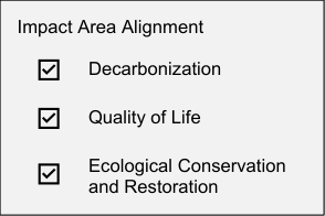
Location and Transportation Credit
COMPACT AND CONNECTED DEVELOPMENT
LTc1
1–8 points
INTENT
To conserve land and ecosystem resources by encouraging development in areas with existing infrastructure. To promote livability, walkability, and transportation efficiency, including reduced vehicle distance traveled and associated emissions.
REQUIREMENTS
| Achievement pathways | Points |
|---|---|
Commercial Interiors | 1–8 |
Option 1. LEED BD+C-certified Base Building | 1–8 |
OR | |
Option 2. Surrounding Density | 1–3 |
AND/OR | |
Option 3. Access to Transit | 1–5 |
AND/OR | |
Option 4. Walkable Location | 1–3 |
Option 1. Base Building Certified with LEED BD+C (1–8 points)
Locate in a building certified with LEED v4/v4.1 BD+C that earned either LTc: Surrounding Density and Diverse Uses or LTc: Access to Quality Transit, or locate in a building certified with LEED v5 BD+C that earned LTc1: Compact and Connected Development.
Table 1. Points for buildings certified with LEED BD+C
| Rating system | Credit | Points earned | Equivalent ID+C points |
|---|---|---|---|
| LEED v4 or LEED v4.1 | _LTc: Surrounding Density and Diverse _ _Uses _ | 1 | 1 |
| LEED v4 or LEED v4.1 | _LTc: Surrounding Density and Diverse _ _Uses _ | 2 | 2 |
| LEED v4 or LEED v4.1 | _LTc: Surrounding Density and Diverse _ _Uses _ | 3 | 3 |
| LEED v4 or LEED v4.1 | _LTc: Surrounding Density and Diverse _ _Uses _ | 4 or more | 4 |
| LEED v4 or LEED v4.1 | LTc: Access to Quality Transit | 1 | 1 |
| LEED v4 or LEED v4.1 | LTc: Access to Quality Transit | 2–3 | 3 |
U.S. Green Building Council LEED v5 Reference Guide for Interior Design and Construction, April 2025 Launch Edition 42
PDF Page 54
| Rating system | Credit | Points earned | Equivalent ID+C points |
|---|---|---|---|
| 4–6 | 4 | ||
| LEED v5 | _LTc1: Compact and Connected _ Development | 1 | 1 |
| LEED v5 | _LTc1: Compact and Connected _ Development | 2–4 | 4 |
| LEED v5 | _LTc1: Compact and Connected _ Development | 5–6 | 8 |
OR
Meet any combination of the options below for a maximum of 8 points.
Option 2. Surrounding Density (1–3 points)
Locate in a building where the surrounding existing density within 0.25 miles (400 meters) offset of the project boundary meets the values in Table 2. Use either the “separate residential and nonresidential densities” or the “combined density” values.
Table 2. Points for average existing density within 0.25 miles (400 meters)
| Combined density | Col2 | Separate density | Col4 | Col5 | Points |
|---|---|---|---|---|---|
| Sq. ft. per acre of buildable land | Sq. m. per hectare of buildable land | Residential density (DU/acre) | Residential density (DU/hectare) | Nonresidential density (FAR) | |
22,000 | 5,050 | 7 | 17.5 | 0.5 | 2 |
| 35,000 | 8,035 | 12 | 30 | 0.8 | 3 |
NOTE: DU = dwelling unit; FAR = floor area ratio
AND/OR
Option 3. Access to Transit (1–5 points)
Locate any functional entry of the building in which the project is located within either:
-
A walking distance of 0.25 miles (400 meters) by existing or planned bus, streetcar, or informal transit stops
-
A walking distance of 0.25 miles (800 meters) by existing or planned bus rapid transit stops, passenger rail stations (i.e., light, heavy, or commuter rail), or commuter ferry terminals
The transit service at these stops and stations in aggregate must meet the minimums listed in Table 3.
U.S. Green Building Council LEED v5 Reference Guide for Interior Design and Construction, April 2025 Launch Edition 43
PDF Page 55
Both weekday and weekend trip minimums must be met. For each qualifying transit route, only trips in one direction are counted toward the threshold.
- If service varies by day:
o For weekday trips, count the weekday with the lowest number of trips.
o For weekend trips, only count the weekend day with the highest number of trips.
-
If a qualifying transit route has multiple stops within the required walking distance, only trips from one stop are counted toward the threshold.
-
Planned stops and stations may count if they are sited, funded, and under construction by the date of the LEED project’s certificate of occupancy and are complete within 24 months of that date.
Table 3. Minimum daily public transit service
| Weekday trips | Weekend trips | Points |
|---|---|---|
| 72 | 30 | 2 |
| 132 | 78 | 3 |
| 160 | 120 | 4 |
| 360 | 216 | 5 |
AND/OR
Option 4. Walkable Location (1–3 points)
Locate in a building that meets the location efficiency requirements in Table 4 via Walk Score ® or proximity to existing and publicly available uses within a walking distance of 0.25 miles (800 meters) from any functional entry.
Table 4. Points for location efficiency
| Walk Score® | Proximity to uses | Points |
|---|---|---|
| 60–69 | 4–7 | 1 |
| 70–79 | 8–10 | 2 |
| 80 or more | ≥ 11 | 3 |
The following restrictions apply:
-
A use may be counted as only one use type (e.g., a retail store may be counted only once even if it sells products in several categories).
-
No more than two uses in each use type may be counted (e.g., if five restaurants are within walking distance, only two may be counted).
-
The counted uses must represent at least three of the five categories.
U.S. Green Building Council LEED v5 Reference Guide for Interior Design and Construction, April 2025 Launch Edition 44
PDF Page 56
REQUIREMENTS EXPLAINED
This credit awards project sites near essential services and in densely built locations with existing infrastructure. There are multiple paths to achieving credit compliance. Project teams should review the site location and the urban context of the project, including building density, community amenities, and public transportation routes, to optimize the options selected for the project.
Option 1. Base Building Certified with LEED BD+C
Projects pursuing LEED ID+C: Commercial Interiorscertification rely on base building elements for many credits. Prioritizing base buildings that have implemented sustainable practices or achieved LEED BD+C certification gives tenants the opportunity to leverage these initiatives for their spaces.
For LEED ID+C: Commercial Interiors projects, locate in a building certified with LEED BD+C, using versions LEED v4 or LEED v4.1, that earned either the LT Credit: Surrounding Density and Diverse Uses or LT Credit: Access to Quality Transit, or locate in a building certified with LEED BD+C under LEED v5 that earned LTc3: Compact and Connected Development .
Determining LEED BD+C Base Building compliance The LEED ID+C: Commercial Interiorsteam must demonstrate that the base building achieved certification under the LEED v4, LEED v4.1, or LEED v5 BD+C rating system and earned points for the respective credits.
USGBC maintains an online directory of certified projects. Information in the directory includes rating system version, level of certification, a copy of the final scorecard, and the project’s unique LEED identification number. Teams can access the project directory at: usgbc.org/projects.
For projects not listed in the USGBC project directory, the LEED ID+C: Commercial Interiors team must contact the base building owner or property manager to validate the project information.
Option 2. Surrounding Density
Projects in high-density areas are likely to be more walkable and offer greater amenities. Additionally, a denser and more compact neighborhood increases efficiency and reduces the time needed to travel from one location to another. It provides easier access to basic services, including supermarkets, pharmacies, banks, medical clinics, and offices. People can choose
U.S. Green Building Council LEED v5 Reference Guide for Interior Design and Construction, April 2025 Launch Edition 45
PDF Page 57
alternative means of travel when amenities are closely located. More important, high surrounding density promotes efficient land use and achieves more sustainable growth patterns that protect natural habitats, farmland, and open spaces. This approach ultimately leads to more resilient and livable communities.
Project teams must identify the building site and buildable land within 0.25 miles (400 meters) offset of the project boundary on a map. Team should collect information on surrounding residential and nonresidential building densities, including the number of dwelling units and building floor area for all properties within the offset of the boundary, and confirm residential densities and floor area ratios (FAR) meet or exceed a residential density of seven or 12 dwelling units (DU)/acre (17.5 or 30 DU/hectare) and a nonresidential density (FAR) of 0.5 or 0.8 using separate density measurements. Projects must meet the 22,000 or 35,000 sf/ acre of buildable land for combined density. A density of seven DU/acre is the minimum required to support public transit. The FAR and buildable land thresholds support this density level.
Option 3. Access to Transit
A project located in a densely built environment with a compact and connected transportation and infrastructure network reduces environmental impact and enhances the quality of life for regular occupants. When people take public transportation, fewer private vehicles occupy the road, which reduces VMT and associated GHG emissions and air pollution. Additionally, buildings close to public transportation significantly promote equity by providing various benefits to communities, particularly underserved/disadvantaged ones. These buildings offer accessibility and mobility to people without private vehicles and foster social interaction by connecting different neighborhoods.
Teams pursuing this option must identify transit stops within the required walking distance from the project’s functional entry to existing or planned transit. Types of transit may include bus, streetcar, bus rapid transit, rail, ferry, or informal transit stops. Teams must provide maps with all available and relevant public transportation options, and/or those that will be available within 24 months of the certificate of occupancy. Teams must measure all stops along walking routes from the main entrance of the project site. Teams must also provide detailed information of the transit services’ location, frequency, and routes, confirming the minimum number of daily trips is met or exceeded. Projects should prioritize locations with multiple types of transit to optimize transportation options for building occupants.
U.S. Green Building Council LEED v5 Reference Guide for Interior Design and Construction, April 2025 Launch Edition 46
PDF Page 58
Option 4. Walkable Location
Walk Score® Knowing the Walk Score® of the project site provides a better understanding of how the building location can encourage physical activity, reduce GHG emissions, and foster social interactions. [18]
Walk Score® data is categorized as either “supported” or “unsupported.” A supported Walk Score® is based on verified, publicly available data and can be used to demonstrate compliance with walkability requirements for credit achievement. An unsupported Walk Score®, however, relies on incomplete or estimated data and cannot be used to achieve this credit.
A high Walk Score® means that the location is highly walkable, and that area is likely to have many amenities and services within a short walking distance. A location with a low Walk Score® indicates that the location is not as walkable or building users would most likely rely heavily on public or private transit for daily activities.
Projects must be located on a site with a Walk Score® of at least 60. Sites without an official Walk Score® can still be used. In areas where Walk Score® is not applicable, use local surveys and observational studies instead.
Location efficiency Locating a project close to existing and publicly available uses can significantly improve the neighborhoods’ quality of life and achieve multiple social benefits. People have easy access to basic amenities such as parks, restaurants, supermarkets, medical clinics, and educational facilities, which promote a vibrant and interconnected community. Increased walkability encourages building users to walk or bike to their destinations, promoting healthier, more active lifestyles. A reduced dependence on cars directly results in reduced VMT, reduced GHG emissions, and improved outdoor air quality.
The project team must map eligible existing uses or planned uses. Planned uses must be available within one year of the date of a project’s certificate of occupancy. Existing and planned uses must be classified with the use types in supplementary LEED guidance published by USGBC. The team should conduct site visits and use satellite imagery or aerial photography to map out the walking routes from the project’s main entrance to all eligible uses. To ensure a diverse and balanced mix of amenities and services that cater to different needs (e.g., dining, shopping, recreation, healthcare), the counted uses must represent at least three of the five categories, exclusive of the building’s primary use category.
18 “Get your Walk Score®”, Walk Score®, accessed March 31, 2025, https://www.walkscore.com/.
U.S. Green Building Council LEED v5 Reference Guide for Interior Design and Construction, April 2025 Launch Edition 47
PDF Page 59
DOCUMENTATION
| Project types | Options | Paths | Documentation |
|---|---|---|---|
| All | Option 1. Base Building Certified with LEED BD+C | All | Confirmation that the project is located in a building certified with LEED v4/v4.1 BD+C that earned the either the LT Credit: Surrounding Density and Diverse Uses or_LT_ _Credit: Access to Quality Transit_OR the project is located in a building certified with LEED v5 BD+C that earned the LTc3: Compact and Connected Development. |
| All | Option 1. Base Building Certified with LEED BD+C | All | Equivalent LEED ID+C: Commercial Interiors Points Earned |
| All | Option 2. Surrounding Density | Combined Density | Vicinity map showing buildable land, any nonbuildable land excluded, project site, and footprint of existing buildings within 0.25 miles (400 meters) offset from the project site. |
| All | Option 2. Surrounding Density | Combined Density | LEED v5 Surrounding Density calculator, completed for Combined Density. |
| All | Option 2. Surrounding Density | Combined Density | Combined density (in sq. ft. per acre or sq. meters per hectare). |
| All | Option 2. Surrounding Density | Separate Density | Vicinity map showing buildable land, any non-buildable land excluded, project site, and footprints of existing residential and nonresidential buildings within 0.25 miles (400 meters) offset from the project site. |
| All | Option 2. Surrounding Density | Separate Density | LEED v5 Surrounding Density calculator, completed for Separate Density. |
| All | Option 2. Surrounding Density | Separate Density | Nonresidential commercial density (in floor area ratio). |
| All | Option 2. Surrounding Density | Separate Density | Residential density (in dwelling units per acre or per hectare). |
| All | Option 3. Access to Transit | All | Vicinity map indicating the project location, location of the transit stop(s), routes serving each stop, and the walking routes (with walking distance noted) between the location of the project functional entry and the stop(s). |
| All | Option 3. Access to Transit | All | Weekday and weekend route schedules showing the frequency of trips and service. |
| All | Option 3. Access to Transit | All | For any planned transit service, documentation of planned transit stops and stations sited, funded, and under construction by the date of the project’s certificate of occupancy and scheduled for completion within 24 months of that date |
| All | Option 4. Walkable Location | Location Efficiency | Walk Score® document (e.g., screenshot) showing the score for the project’s address. |
| All | Option 4. Walkable Location | Location Efficiency | Project’s Walk Score®. |
| All | Option 4. Walkable Location | Public Uses | Vicinity map and table of uses identified by type of uses accessible within a walking distance of 0.5 miles (800 meters). |
REFERENCED STANDARDS
U.S. Green Building Council LEED v5 Reference Guide for Interior Design and Construction, April 2025 Launch Edition 48
PDF Page 60
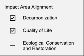
Location and Transportation Credit
TRANSPORTATION DEMAND MANAGEMENT
LTc2
1–4 points
INTENT
To reduce pollution and land development effects from automobile use through encouraging alternative transportation networks. To promote more livable and healthy communities through reduced vehicle miles traveled (VMT ) and reduced associated emissions.
REQUIREMENTS
| Achievement pathways | Points |
|---|---|
Commercial Interiors | 1–4 |
Transportation Demand Assessment | |
AND | |
Option 1. Parking | 1–3 |
Path 1. Reduce Parking | 1–3 |
AND/OR | |
Path 2. Unbundle Parking | 2 |
AND/OR | |
Option 2. Active Travel Facilities | 1–3 |
Path 1. Base Building certified with LEED BD+C | 1–2 |
OR | |
Path 2. Active Travel Facilities in Base Building | 1–2 |
AND/OR | |
Option 3. Compliant Base Building | 1 |
Path 1. Bicycle Network and Storage | 1 |
AND/OR | |
Path 2. Base Building Shower and Changing Facilities | 1 |
AND/OR | |
Path 3. Tenant Space Shower and Changing Facilities | 1 |
AND/OR | |
Path 4. Bicycle Maintenance | 1 |
Transportation Demand Assessment
Assess the number of VMT and carbon emissions associated with regular building occupants’ travel to and from the project building as outlined below:
-
Estimate the annual VMT .
-
Estimate annual baseline case for carbon emissions.
-
Assess low-carbon transportation options.
U.S. Green Building Council LEED v5 Reference Guide for Interior Design and Construction, April 2025 Launch Edition 49
PDF Page 61
-
Estimate annual proposed case for carbon emissions.
- Estimate the total reduction of carbon emissions between annual baseline case and annual proposed case.
Projects that participate in a local or regional government-mandated TDM program satisfy the transportation demand assessment requirement. Residential affordable housing projects in an infill location or an office, mixed-use, residential, or retail project located within a transit priority area, or within 0.5 miles (800 meters) walking distance of an existing or planned major transit stop, are exempt from the above requirements.
AND
Implement one or more of the following strategies for up to a total of 4 points.
Option 1. Parking (1–3 points)
PATH 1. REDUCE PARKING (1–3 POINTS)
Locate in a building that provides a reduction in parking capacity using the base ratios for parking spaces found in the Institute of Transportation Engineers Parking Generation Manual, sixth edition, or a comparable resource applied by a qualified transportation engineer or planner or in supplementary LEED guidance. Points are awarded according to Table 1.
Table 1. Points for percentage of reduced parking capacity
| Reduced parking percentage | Points |
|---|---|
30% reduction from base ratios | 1 |
| 60% reduction from base ratios | 2 |
| 100% reduction from base ratios (no parking) | 3 |
AND/OR
PATH 2. UNBUNDLE PARKING (2 POINTS)
Unbundle parking by purchasing parking separately from the tenant space lease. Do not provide free parking for employees. Implement a daily, monthly, or annual parking fee at a cost equal to or greater than the local market rate for public or private parking.
AND/OR
U.S. Green Building Council LEED v5 Reference Guide for Interior Design and Construction, April 2025 Launch Edition 50
PDF Page 62
Option 2. Active Travel Facilities (1–3 points)
PATH 1. BASE BUILDING CERTIFED WITH LEED BD+C (1–2 POINTS)
Locate in a building certified with LEED BD+C under LEED v4 or LEED v4.1 that earned LTc: Bicycle Facilities, or in a building certified with LEED v5 BD+C that earned LTc2: Transportation Demand Management.
Table 2. Points for LEED BD+ C certified building
| Certification | Credit name | Points earned | Equivalent LEED ID+C points |
|---|---|---|---|
| LEED v4 or LEED v4.1 | LTc: Bicycle Facilities | 1 | 2 |
| LEED v5 | LTc2: Transportation Demand Management | 1 | 1 |
| LEED v5 | LTc2: Transportation Demand Management | 2 | 2 |
OR
PATH 2. ACTIVE TRAVEL FACILITIES IN BASE BUILDING (1–2 POINTS)
Locate in a building that meets the requirements for Option 3, Compliant Base Building, Path 1, for 1 point. Meet Option 3, Compliant Base Building, Path 2, for 1 additional point.
AND/OR
Option 3. Compliant Base Building (1 point)
PATH 1. BICYCLE NETWORK AND STORAGE (1 POINT)
Bicycle Network Locate the project in a building such that a functional entry and/or bicycle storage is within a 600-foot (180-meter) walking distance or cycling distance of a bicycle network that meets the following criteria:
-
It is a contiguous network that spans a distance of at least 3 miles (4,800 meters).
-
It consists of bicycle paths, lanes, multiuse trails, or streets with a maximum speed limit of 25 mph (40 kph). Sidewalks where local code permits bicycles are acceptable.
Planned bicycle trails or lanes may be counted if they are fully funded by the date of the certificate of occupancy and are scheduled for completion within three years of that date.
AND
Bicycle Storage Provide short-term bicycle storage within a 600-foot (180-meter) walking distance of any main entrance, and with no fewer than four storage spaces per building.
U.S. Green Building Council LEED v5 Reference Guide for Interior Design and Construction, April 2025 Launch Edition 51
PDF Page 63
Provide long-term bicycle storage within a 300-foot (90-meter) walking distance of any functional entry, but with no fewer than four storage spaces per building in addition to the shortterm bicycle storage spaces.
Points are awarded according to Table 3 below.
Shared micromobility storage, bicycle-sharing stations, and/or publicly available bicycle parking may be counted for up to 50% of the required short-term and long-term storage space if it meets the maximum allowable walking distance, and is not double-counted (i.e., the short-term and the long-term storage spaces are counted separately), and the storage location is communicated to the building occupants and visitors.
Table 3. Number of spaces required for short- and long-term bicycle storage
| Storage type | Commercial, institutional, healthcare | Retail |
|---|---|---|
Short-term | At least 2.5% of all peak visitors but no fewer than four spaces per building | At least two short-term bicycle storage spaces for every 5,000 sq. ft. (465 sq. m.) but no fewer than two storage spaces per building |
| Long-term | At least 5% of all regular building occupants but no fewer than four storage spaces per building in addition to short- term storage | At least 5% of regular building occupants but no fewer than two storage spaces per building in addition to the short-term bicycle storage spaces |
NOTE: Healthcare projects can exclude patients from the regular building occupant count for long-term storage.
AND/OR
PATH 2. BASE BUILDING SHOWER AND CHANGING FACILITIES (1 POINT)
Locate the facilities in a building that provides access to on-site showers with changing facilities for 1% of all regular building occupants. Off-site showers and changing facilities are acceptable if they meet the needs of all occupants and are within a walking distance of 0.25 miles (400 meters).
AND/OR
PATH 3. TENANT SPACE SHOWER AND CHANGING FACILITIES (1 POINT)
Provide at least one shower within the tenant space with a changing facility for the first 100 regular building occupants and one additional shower for every 150 regular building occupants thereafter.
U.S. Green Building Council LEED v5 Reference Guide for Interior Design and Construction, April 2025 Launch Edition 52
PDF Page 64
Large Occupancy Projects Provide at least one on-site shower within the tenant space with a changing facility for the first 100 regular project occupants and one additional shower for every 150 regular project occupants thereafter, up to 999 regular project occupants. Thereafter, provide:
-
One additional shower for every 500 regular project occupants, for an additional 1,000– 4,999 regular project occupants
-
One additional shower for every 1,000 regular building occupants, for an additional 5,000+ regular project occupants
AND/OR
PATH 4. BICYCLE MAINTENANCE (1 POINT)
Provide a permanently secured bicycle repair station that includes a complete set of tools, and an air pump securely fastened to the repair stand in the area dedicated to long-term bicycle storage.
REQUIREMENTS EXPLAINED
This credit provides a holistic approach to reducing transportation impacts and supporting decarbonization efforts for projects by managing travel behavior and enhancing accessibility options. TDM includes both facility-related and behavioral strategies to encourage sustainable transportation choices. TDM strategies may target facilities specifically related to the project, such as bicycle maintenance stations, secure bicycle storage, and access to connected bicycle networks (paths, trails, designated bicycle lanes). These strategies, however, go hand in hand with behavioral approaches that involve offering incentives or disincentives, conducting educational campaigns, and promoting flexible work locations. TDM helps reduce VMT, lower parking demand, support ridesharing, and encourage public transit use by evaluating the current and projected transportation demands of project occupants. The credit examines commuting patterns and behaviors of the occupants by estimating VMT and assessing alternative mode choices, making TDM a comprehensive framework for sustainable transportation planning.
Project teams pursuing this credit should adopt from a list of TDM strategies that can be implemented in the project to model good transportation habits.
Transportation Demand Assessment
Sustainable transportation measures require assessing the number of VMT and carbon emissions associated with the regular project occupants’ travel to and from the project building. VMT and carbon emissions are important metrics in evaluating the impacts of transportation and efforts toward creating a more sustainable transportation system. They provide critical data for
U.S. Green Building Council LEED v5 Reference Guide for Interior Design and Construction, April 2025 Launch Edition 53
PDF Page 65
guidance in creating effective TDM strategies and insights in designing projects that aim to reduce travel distances, encourage alternative transportation modes, and lead to more sustainable and resilient communities. USGBC will provide a calculator to help to complete the calculations below.
Projects that participate in a local or regional government-mandated TDM program are considered to have met the Transportation Demand Assessment requirement because these programs are typically designed to achieve the same goals of reducing traffic congestion, lowering emissions, and supporting more sustainable transportation systems. Residential affordable housing projects in infill locations, as well as office, mixed-use, residential, or retail projects located within a Transit Priority Area or within a walking distance of 0.5 miles (800 meters) from an existing or planned major transit stop, are exempt from the TDM assessment requirements because their location inherently promotes sustainable transportation options, high trip frequency, and close proximity to sustainable transportation alternatives.
Estimate the annual VMT Project teams must estimate the annual VMT as part of assessing transportation demand. This process involves determining the number of days the project will be occupied, identifying the number of regular project occupants commuting to and from the site - using either actual occupant data or supplementary LEED guidance published by USGBC - and calculating the VMT. Project teams can refer to federal transportation reports, data from metropolitan planning organizations, and information from local or state transportation departments to estimate commute distances accurately. If local data cannot be found, consider a regional source. These resources provide insights into average commute lengths, which help refine the VMT calculation and support the development of effective TDM strategies. Equation 1. Calculating the total annual VMT 𝑇 𝑇 𝑇𝑇 𝑎 𝑎 𝑎 𝑉 𝑉𝑉= 𝑅 𝑅 𝑅 𝑅𝑅 𝑝 𝑝 𝑝 𝑝𝑝 𝑜 𝑜 𝑜 𝑜 𝑜𝑜 ×
𝑁 𝑁 𝑁 𝑜 𝑑 𝑑 𝑤 𝑤𝑤ℎ𝑖 𝑎𝑎 𝑦 𝑦 𝑎 𝑎 𝑎𝑎 𝑏 𝑏 𝑏 𝑏 𝑜 𝑜 𝑜 𝑜 𝑜 × 𝐷 𝐷 𝐷𝐷 𝑉 𝑉𝑉 Estimate annual baseline case for carbon emissions Project teams must estimate the annual baseline case for carbon emissions. Teams should identify a vehicle emissions factor for a typical passenger vehicle, such as the amount of CO2 emitted per unit of distance traveled. This factor serves as the foundation for estimating transportation-related emissions from commuting to and from the project building in a singleoccupancy vehicle. While it is not necessary to account for multiple fuel types or vehicle models, the emissions factor should reflect an average vehicle commonly used in the region. All trips are assumed to be a single mode of travel. Once the emissions factor is determined, teams must calculate annual baseline emissions based on a worst-case scenario, which assumes maximum
U.S. Green Building Council LEED v5 Reference Guide for Interior Design and Construction, April 2025 Launch Edition 54
PDF Page 66
vehicle usage and commuting distances without mitigation efforts. This baseline provides a comprehensive view of the project’s potential carbon impact from commuting transportation. Equation 2. Calculating annual baseline case for transportation emissions 𝐴 𝐴 𝐴 𝑏 𝑏 𝑙 𝑙 𝑐 𝑐 𝑓 𝑓𝑓 𝑡 𝑡 𝑡 𝑡 𝑡 𝑡 𝑡 𝑒 𝑒 𝑒 𝑒 𝑒𝑒= 𝑇 𝑇 𝑇𝑇 𝑎 𝑎 𝑎 𝑉 𝑉𝑉 × 𝐸 𝐸 𝐸 𝐸 𝑓 𝑓 𝑓
Assess low-carbon transportation options After the baseline for annual transportation emissions has been established, teams must assess the potential for reducing transportation-related emissions by utilizing data from national census, metropolitan planning organizations, and transportation departments at local or state governments. Teams should use other relevant data sources to estimate actual travel patterns, if local or state data cannot be found. Based on the findings, teams must also estimate the portion of regular project occupants likely to use these alternative and active transportation options for their daily commutes to and from the project building. Teams are strongly encouraged to prioritize Option 1: Parking and Option 2: Active Travel Facilities, as these options support the promotion of low-carbon transportation strategies. Teams should also account for unique conditions at the larger building site and assess whether the travel estimates are realistic. Consider transportation facilities that are available to all tenants in the building.
Key guiding questions include:
-
Are there bikeable routes leading to the project?
-
Is there sufficient sidewalk connectivity?
-
Is the project within walking distance of a residential neighborhood?
Walking and biking trips, which assume zero emissions, can significantly offset the overall transportation carbon footprint of the project.
Estimate annual proposed case for carbon emissions After assessing the low-carbon transportation option, project teams must determine the anticipated number of regular project occupants who will commute using single-occupancy vehicles, based on a realistic assessment of travel patterns to and from the site. This analysis should account for various commuting methods, such as walking, cycling, public transit or carpooling, and estimate the remaining number of individuals who are likely to rely on singleoccupancy vehicles. For example, if 50 employees are expected to regularly walk to and from work, these individuals would produce no vehicle emissions for the year. Equation 3. Calculate annual transportation emissions 𝐴 𝐴 𝐴 𝑡 𝑡 𝑡 𝑡 𝑡𝑡𝑎 𝑎 𝑎𝑎 𝑒 𝑒 𝑒 𝑒 𝑒𝑒=
U.S. Green Building Council LEED v5 Reference Guide for Interior Design and Construction, April 2025 Launch Edition 55
PDF Page 67
(𝑅 𝑅 𝑅 𝑅𝑅 𝑝 𝑝 𝑝 𝑝𝑝 𝑜 𝑜 𝑜 𝑜 𝑜𝑜 𝑡𝑡ℎ𝑎 𝑑 𝑑 𝑑 × 𝑛 𝑛 𝑛 𝑜 𝑑 𝑑 𝑤 𝑤𝑤ℎ𝑖 𝑎𝑎 𝑦 𝑦 𝑎 𝑎 𝑎𝑎 𝑝 𝑝 𝑝 𝑝𝑝 𝑜 𝑜 𝑜 𝑜 𝑜 ×
𝐷 𝐷 𝐷𝐷 𝑟 𝑟 𝑟𝑟 𝑡 𝑡 𝑉 𝑉𝑉) 𝑥𝑥 𝐸 𝐸 𝑠𝑠𝑖 𝑖𝑖 𝑓 𝑓 𝑓 Estimate the total reduction of carbon emissions Project teams are required to calculate the difference in emissions to get the total estimated reduction of carbon emissions between the annual baseline and proposed case.
Option 1. Parking
TDM strategies, like reducing parking spaces and implementing parking fees, tackle broader land use and cost challenges tied to parking. By decreasing the need for large parking facilities, TDM conserves valuable land and reduces infrastructure and maintenance expenses, promoting more sustainable transportation options that align with project efficiency and environmental goals.
Limiting parking availability also helps curb induced demand, as fewer parking spaces discourage single-occupancy vehicle (SOV) trips and encourage alternative transportation modes. Another effective approach is unbundling parking, which separates the cost of parking from building rentals or leases. For instance, a mixed-use office building leases commercial spaces to businesses. Instead of including parking spaces as part of the standard lease package, the building owner offers parking spaces as a separate, optional service.
PATH 1. REDUCE PARKING
Limiting parking availability also helps curb induced demand, as fewer parking spaces discourage SOV trips and encourage alternative transportation modes. This path uses a parking baseline against which reductions in parking supply can be compared.
First, identify the total baseline capacity of parking. Teams should determine the total baseline parking capacity using the base ratios from The Institute of Transportation Engineers’ Parking Generation Manual [19] or supplementary LEED guidance published by USGBC. If the project type does not fit any base ratio category or if the tenant is not yet known, select the best approximation (i.e., the most applicable land use type for the anticipated tenant) and provide a narrative justifying this selection. For projects with multiple space types, calculate and separately track the base ratio for each use and compute the total project baseline capacity.
Next, teams must identify the total provided capacity they will supply based on their needs assessment. Count both new and existing spaces.
19 “Parking Generation Manual”, The Institute for Transportation Engineers, accessed March 31, 2025, https://www.ite.org/technicalresources/topics/trip-and-parking-generation/.
U.S. Green Building Council LEED v5 Reference Guide for Interior Design and Construction, April 2025 Launch Edition 56
PDF Page 68
Last, teams must determine whether the total provided capacity is less than the baseline capacity calculated from the base ratios above. Calculate the percent parking reduction. Teams should design projects that minimize parking demand. Integrate TDM strategies to reduce the project’s parking demand, especially if achieving a significant parking reduction is the primary goal.
Equation 4. Percentage of parking capacity reduction
[𝑻] [𝑻][ 𝒃] [𝒃] [𝒃] [𝒃] [ 𝒄] [𝒄] [𝒄] [𝒄] −𝑻 𝑻 𝑻 𝒑 𝒑 𝒑 𝒑 𝒄 𝒄 𝒄𝒊 𝒊)
𝑷 𝑷 𝑷 𝑷𝑷 𝒓 𝒓 𝒓 𝒓 𝒓𝒓= [(𝑻] × 𝟏 𝟏𝟏
𝑻 𝑻 𝑻 𝒃 𝒃 𝒃 𝒃 𝒄 𝒄 𝒄 𝒄
PATH 2. UNBUNDLED PARKING
In tenant-occupied projects, parking spaces are frequently bundled with leases, meaning tenants pay for parking regardless of vehicle ownership. Unbundling parking spaces separates parking costs from lease or purchase costs, allowing tenants who do not own a vehicle to save money. This strategy helps reduce the parking demand for the project and can lower housing costs, as tenants who do not require parking are not paying for it. More importantly, unbundling brings visibility to the true cost of parking, which includes not only construction costs but also land use, maintenance, environmental, social, and economic impacts.
For both tenant- and owner-occupied projects, an effective strategy is to charge market-rate fees for parking spaces, aligning the cost with local rates and discouraging unnecessary car use. In owner-occupied projects, this involves requiring all employees to pay for parking, creating a consistent policy across occupants that encourages carpooling, active transportation, and public transit use. By charging for parking at market rates, project teams reinforce the understanding of parking’s true cost and promote more sustainable transportation choices.
To comply with this option, the project must unbundle all parking spaces within the project boundary from the tenant lease or sales. The project must make this commitment for its entire duration. This will allow tenants the option of renting or buying as many spaces as needed, with an additional cost. It also allows projects that do not want parking spaces the option to save money by not having the cost built into the rent.
Option 2. Active Travel Facilities
Active travel facilities promote sustainable, healthy, and efficient alternatives to car-based transportation by providing comprehensive facilities that support cycling, e-bicycles, scooters, and other eco-friendly travel modes. Essential components include secure storage for bikes, well-designed on-road facilities such as dedicated lanes and paths, access to showers and
U.S. Green Building Council LEED v5 Reference Guide for Interior Design and Construction, April 2025 Launch Edition 57
PDF Page 69
changing areas, and bike maintenance stations. Together, these elements create an integrated system that enables convenient, active travel options for daily commuting and short trips. In recent years, these modes have surged in popularity; as of 2017, there were around 1,250 bicycle-sharing systems globally with over 10 million bicycles. [20 ] Active transportation not only reduces carbon emissions and improves public health through increased physical activity but also helps manage transportation demand by reducing traffic congestion and lessening the need for parking infrastructure.
PATH 1: BASE BUILDING CERTIFIED WITH LEED BD+C
Projects must locate the LEED ID+C: Commercial Interiors project within a building certified with LEED BD+C under LEED v4 or LEED v4.1 that earned the LT credit: Bicycle Facilities, or in a building certified with LEED BD+C under LEED v5 that earned the LTc4: Transportation Demand Management. Early collection of certification information can streamline the process by identifying relevant credits and systems.
PATH 2. ACTIVE TRAVEL FACILITIES IN BASE BUILDING
Projects must be in a building that meets the criteria for Option 3: Compliant Base Building, Path 1 to earn one point. To earn an additional point, they must also meet the requirements for Option 3: Compliant Base Building, Path 2.
Option 3. Compliant Base Building
Active travel facilities promote sustainable, healthy, and efficient alternatives to car-based transportation by providing comprehensive facilities that support cycling, e-bicycles, scooters, and other eco-friendly travel modes. Essential components include secure storage for bikes, well-designed on-road facilities such as dedicated lanes and paths, access to showers and changing areas, and bike maintenance stations. Together, these elements create an integrated system that enables convenient, active travel options for daily commuting and short trips. In recent years, these modes have surged in popularity, and, as of 2017, there were around 1,250 bicycle-sharing systems globally with over 10 million bicycles. [21] Active transportation not only reduces carbon emissions and improves public health through increased physical activity but also helps manage transportation demand by reducing traffic congestion and lessening the need for vehicle parking infrastructure.
20 “Sustainable Transport, Sustainable Development: Interagency Report for Second Global Sustainable Transport Conference,” United Nations, accessed April 5, 2025, https://sdgs.un.org/sites/default/files/202110/Transportation%20Report%202021_FullReport_Digital.pdf. 21 “Sustainable Transport, Sustainable Development: Interagency Report for Second Global Sustainable Transport Conference,” United Nations, accessed April 5, 2025, https://sdgs.un.org/sites/default/files/202110/Transportation%20Report%202021_FullReport_Digital.pdf.
U.S. Green Building Council LEED v5 Reference Guide for Interior Design and Construction, April 2025 Launch Edition 58
PDF Page 70
PATH 1. BICYCLE NETWORK AND STORAGE
To promote bicycle-friendly design, this path rewards two factors: the provision of long- and short-term bicycle storage, and access to a bicycle network (paths, trails, designated bicycle lanes, and slow-speed roadways). Project teams consider short-term and long-term bicycle storage capacity separately because visitors and regular project occupants have different bicycle storage needs. Being adjacent to a bicycle network means that project occupants can more easily bicycle to and from the project building.
Bicycle network Project teams should identify bicycle network within a 600-foot (180-meter) walking distance or bicycling distance of a functional entry and/or bicycle storage in project and gather information and specifications on distance from the project site and street speed limit for the bicycle network. A bicycle network must be a contiguous system that spans a distance of three miles (4,800 meters). The three-mile contiguous path refers to the total length and does not need to span three miles in a single direction. For example, it could consist of one mile to the north and two miles to the south, totaling three miles. The bicycle network must also consist of bicycle lanes, bicycle trails, and streets with a maximum speed limit of 25 mph (40 km/h). Both bicycle lanes and bicycle trails must meet the credit’s width requirements. Sidewalks where bicycles are allowed are acceptable.
Teams must locate the project close to an existing or planned bicycle network that meets credit requirements for uses within the specified distance from the project boundary. For planned bicycle trails or lanes, confirm the schedule for funding and completion.
Bicycle storage Teams are required to determine the number of expected occupants in the project, the number of bicycle storage spaces and shared mobility storage, and the stations required. Once the number of bicycle storage spaces are determined, install the short-term and long-term bicycle storage within 600 feet (180 meters) and 300 feet (90 meters) of walking distance from any main entrance and functional entry, respectively, of the project building. Shared micromobility storage facilities, such as those for e-scooters and e-bicycles, as well as bicycle sharing stations and publicly accessible bicycle parking, can account for up to 50% of the required short-term and long-term bicycle storage needs to encourage the use of communal, readily available transportation solutions, and reduce the need for dedicated on-site storage infrastructure. Teams must also clearly communicate the locations of bicycle storage to project occupants and visitors, whether through building signage, regular newsletters, or posting transportation options to a company’s internal website.
U.S. Green Building Council LEED v5 Reference Guide for Interior Design and Construction, April 2025 Launch Edition 59
PDF Page 71
For commercial, institutional, and healthcare projects, use Equation 5 to determine the number of short- and long-term bicycle storage. Healthcare projects can exclude patients from regular project occupant count for long-term storage.
Equation 5. Calculating bicycle storage for commercial, institutional, schools and healthcare projects
projects 𝑆𝑆ℎ𝑜 𝑜𝑜-𝑡 𝑡 𝑠 𝑠 𝑠 𝑠𝑠= (𝑃 𝑃 𝑣 𝑣 𝑣 𝑣𝑣 × 0.025) ≥4
𝐿 𝐿 -𝑡 𝑡 𝑠 𝑠 𝑠 𝑠𝑠= (𝑅 𝑅 𝑅 𝑅𝑅 𝑝 𝑝 𝑝 𝑝𝑝 occupants 𝑥𝑥 0.05) ≥4 For retail projects, use Equation 6 to determine the number of short- and long-term bicycle storage:
Equation 6. Calculating bicycle storage for retail projects
[𝑩] [𝑩] [𝑩] [ 𝒈] [𝒈] [𝒈][ 𝒇] [𝒇] [𝒇][ 𝒂] [𝒂] [ (𝒔] [ 𝒐] [ 𝒎][²)] 𝑺 𝒐 𝒐𝒐-𝒕 𝒕 𝒔 𝒔 𝒔 𝒔𝒔= � [(𝑩]
𝟓 𝟓 𝒐 𝟒 𝟒
[𝒈] [𝒈][ 𝒇] [𝒇] [𝒇][ 𝒂] [𝒂] [ (𝒔] [ 𝒐] [ 𝒎][²)]
� ≥𝟐𝟐
𝟓 𝟓 𝒐 𝟒 𝟒
𝐿 𝐿 -𝑡 𝑡 𝑠 𝑠 𝑠 𝑠𝑠= (𝑅 𝑅 𝑅 𝑅𝑅 𝑝 𝑝 𝑝 𝑝𝑝 𝑜 𝑜 𝑜 𝑜 𝑜𝑜 × 0.05) ≥2
PATH 2. BASE BUILDING SHOWER AND CHANGING FACILITIES
Providing adequate infrastructure for active commuting, such as lockers and changing/shower facilities, plays a key role in promoting physical activity for all project occupants, not just cyclists. These amenities are especially beneficial for those who may engage in exercise or other physical activities before work. Offering these facilities signals to occupants that active lifestyles, including active commuting, encourage and support a culture that values health and wellness.
Projects must locate in a building that provides access to on-site showers with changing facilities for 1% of all regular project occupants. Off-site showers and changing facilities are acceptab le if they meet the needs of all occupants and are within a walking distance of 0.25 miles (400 meters).
Project teams should gather occupant information and determine the number of shower and changing facilities required, using Equation 7. Teams must provide vicinity or area map indicating off-site shower and changing facilities.
Equation 7. Calculating the number of shower and changing facilities
𝑵 𝑵 𝑵 𝒐 𝒔 𝒔 𝒔 𝒂 𝒂𝒂 𝒄 𝒄 𝒄 𝒄 𝒇 𝒇 𝒇 𝒇 𝒇 = 𝑹 𝑹 𝑹 𝑹𝑹 𝒑 𝒑 𝒑 𝒑𝒑 𝒐 𝒐 𝒐 𝒐 𝒐𝒐 × 𝟎𝟎. 𝟎
U.S. Green Building Council LEED v5 Reference Guide for Interior Design and Construction, April 2025 Launch Edition 60
PDF Page 72
PATH 3. TENANT SHOWER AND CHANGING FACILITIES
Project teams should gather occupant information and determine the number of shower and changing facilities required, using Equation 8. Teams must provide vicinity or area map indicating off-site shower and changing facilities.
Equation 8. Calculating the number of shower and changing facilities for tenant shower and changing facilities
𝐼 𝑟 𝑟 𝑟 𝑟𝑟 𝑝 𝑝 𝑝 𝑝𝑝 𝑜 𝑜𝑜𝑢 𝑢 𝑢 ≤100, 𝑆𝑆ℎ𝑜 𝑜 𝑓 𝑓 𝑓 𝑓 𝑓 = 1
𝐼 𝑟 𝑟 𝑟 𝑟𝑟 𝑝 𝑝 𝑝 𝑝𝑝 𝑜 𝑜 𝑜 𝑜 𝑜𝑜 > 100, 𝑆𝑆ℎ𝑜 𝑜 𝑓 𝑓 𝑓 𝑓 𝑓 = 1 +
𝑅 𝑅 𝑅 𝑅 𝑅 𝑝 𝑝 𝑝 𝑝 𝑜 𝑜 𝑜 𝑜 𝑜−100
150
For large-occupancy projects with additional 1,000 - 4,999 regular building occupants, use Equation 9 to determine the number of shower and changing facilities required.
Equation 9. Calculating the number of shower and changing facilities for large occupancy of 1,000 or more
𝐼 𝑟 𝑟 𝑟 𝑟𝑟 𝑝 𝑜𝑜𝑗 𝑗 𝑜 𝑜 𝑜 𝑜 𝑜𝑜 > 1000, 𝑆𝑆ℎ𝑜 𝑜 𝑓 𝑓 𝑓 𝑓 𝑓 = 1 +
1000
𝐼 𝑟 𝑟 𝑟 𝑟𝑟 𝑝 𝑝 𝑝 𝑝𝑝 𝑜 𝑜 𝑜 𝑜 𝑜𝑜 > 5000, 𝑆𝑆ℎ𝑜 𝑜 𝑓 𝑓 𝑓 𝑓 𝑓 = 1 +
𝑅 𝑅 𝑅 𝑅 𝑅 𝑝 𝑝 𝑝 𝑝 𝑜 𝑜 𝑜 𝑜 𝑜−1000
500
𝑅 𝑅 𝑅 𝑅 𝑅 𝑝 𝑝𝑗𝑒 𝑒 𝑜 𝑜 𝑜 𝑜 𝑜−5000
500
PATH 4. BICYCLE MAINTENANCE
Offering on-site bicycle maintenance services is a strategy to promote active commuting. By providing access to basic bicycle repair tools and air-pump stations, projects can make cycling a more convenient and reliable option for commuters. This proactive support ensures that bicycles remain in good working condition and encourages more individuals to adopt active commuting as part of their daily routine.
Project teams should provide a description of the available bicycle services and facilities, along with a map or site plan, indicating the location of the bicycle repair station within the designated long-term bicycle storage area to ensure that occupants are aware of where to access these resources, making it easier for them to maintain their bicycles and promoting a cyclingsupportive environment.
U.S. Green Building Council LEED v5 Reference Guide for Interior Design and Construction, April 2025 Launch Edition 61
PDF Page 73
DOCUMENTATION
| Project types | Options | Paths | Documentation |
|---|---|---|---|
All | All | Not Claiming TDA Exemption | USGBC TDM Assessment calculator |
All | All | Not Claiming TDA Exemption | Baseline VMT |
All | All | Not Claiming TDA Exemption | Proposed VMT |
All | All | Not Claiming TDA Exemption | Baseline Emissions from VMT |
All | All | Not Claiming TDA Exemption | Proposed Emissions from VMT |
All | All | Not Claiming TDA Exemption | Description of availability of alternative low-carbon and active travel options. |
All | All | Claiming TDA Exemption | Documentation showing participation in a local or regional government mandated TDM program. |
All | All | Claiming TDA Exemption | Documentation showing project is an affordable housing project in an infill location. |
All | All | Claiming TDA Exemption | Documentation showing project (office, mixed-use, residential, or retail) is located within a Transit Priority Area or within a ½-mile (800-meter) walking distance of an existing or planned major transit stop. |
All | Option 1. Parking | Path 1. Reduce Parking | Calculations demonstrating percent reduction in the parking capacity from baseline. |
All | Option 1. Parking | Path 1. Reduce Parking | Parking Plan or Site Plan showing the LEED boundary and the parking used by the project building. |
All | Option 1. Parking | Path 2. Parking Fee | Narrative identifying the parking fees and explaining how the rate charged is equal to or greater than the local market rate for parking. |
All | Option 1. Parking | Path 2. Parking Fee | Documentation confirming local market parking rate. |
All | Option 1. Parking | Path 2. Parking Fee | Confirmation that free parking is not provided for employees. |
All | Option 2. Active Travel Facilities | Path 1. LEED Certified Base Building | LEED Certified Base Building project ID. |
All | Option 2. Active Travel Facilities | Path 1. LEED Certified Base Building | Confirmation that the project is located in a LEED v4/v4.1 certified building that earned the LT: Bicycle Facilities Credit, or in a LEED v5 certified building that earned_LTc4: Transportation Demand Management_. |
All | Option 2. Active Travel Facilities | Path 1. LEED Certified Base Building | Equivalent LEED ID+C: Commercial Interiors points earned. |
All | Option 2. Active Travel Facilities | Path 2. Active Travel Facilities in Base Building | Refer to Option 3. Compliant Base Building, Path 1, and Option 3. Compliant Base Building, Path 2. |
All | Option 3. Compliant Base Building | Path 1. Bicycle Network and Storage | Vicinity map showing bicycle network meeting the required criteria and walking/bicycling distance of functional building entrance and/or bicycle storage to existing or planned bicycle network. |
All | Option 3. Compliant Base Building | Path 1. Bicycle Network and Storage | Confirmation bicycle network meets all criteria identified in the credit requirements. |
All | Option 3. Compliant Base Building | Path 1. Bicycle Network and Storage | Site Plan showing main and functional building entrances, short-term bicycle storage and long-term bicycle storage and shared micromobility storage (if applicable), walking distance from short-term storage |
U.S. Green Building Council LEED v5 Reference Guide for Interior Design and Construction, April 2025 Launch Edition 62
PDF Page 74
| Project types | Options | Paths | Documentation |
|---|---|---|---|
| to the main entrance and from long-term storage to a functional entrance. | |||
| Calculations documenting the percentage of occupants for which short-term bike storage is provided. | |||
Calculations documenting the percentage of occupants for which long-term bike storage is provided. | |||
| Path 2. Base Building Shower and Changing Facilities | Site plan showing shower and changing facilities location and walking distance within 0.25 miles (400 meters) for off-site facilities. | ||
| Path 2. Base Building Shower and Changing Facilities | Calculation documenting the percentage of regular building occupants with access provided to showers with changing facilities. | ||
| Path 2. Base Building Shower and Changing Facilities | For large occupancy projects: the number of project occupants needed to determine the number of on-site showers required. | ||
| Path 2. Base Building Shower and Changing Facilities | For large occupancy projects: the number of on-site showers with changing facilities provided. | ||
| Path 3. Tenant Space Shower and Changing Facilities | Plans showing tenant space shower and changing facilities. | ||
| Path 3. Tenant Space Shower and Changing Facilities | The number of regular project occupants to determine the number of showers with changing facilities required within the tenant space. | ||
| Path 4. Bicycle Maintenance | Evidence of a permanently secured bicycle maintenance facility demonstrating a complete set of tools and air pump securely fastened to the repair stand (e.g., product information from the manufacturer, photographs, contract specification). | ||
| Path 4. Bicycle Maintenance | Evidence of location of the bicycle maintenance facility in the area dedicated to long-term bicycle storage (e.g., contract documents). | ||
| Retail | Retail | Path 1. Bicycle Network and Storage | Number of short-term bike storage spaces provided. |
REFERENCED STANDARDS
- Institute of Transportation Engineers (ITE) Parking Generation Manual, 6th Edition (ite.org/technical-resources/topics/trip-and-parking-generation).
U.S. Green Building Council LEED v5 Reference Guide for Interior Design and Construction, April 2025 Launch Edition 63
PDF Page 75
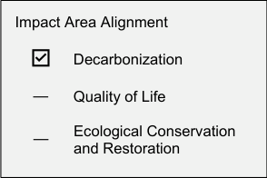
Location and Transportation Credit
ELECTRIC VEHICLES
LTc3
1–2 points
INTENT
To encourage the use of electric vehicles and infrastructure. To help reduce the negative health effects on communities by lowering GHG emissions and other pollutants emitted from conventionally fueled cars and trucks.
REQUIREMENTS
| Achievement pathways | Points |
|---|---|
Commercial Interiors | 1–2 |
Option 1: Base Building Certified with LEED BD+C | 1–2 |
OR | |
Option 2: Electric Vehicle Supply Equipment | 1–2 |
Projects can earn up to 2 points by meeting Option 1 or Option 2.
Option 1. Base Building Certified with LEED BD+C (1–2 points)
Locate in a building certified with LEED v4/v4.1 BD+C or LEED v5 BD+C that earned LTc: Green/Electric Vehicles.
Table 1. Equivalent ID+C points for building certified with LEED BD+C
| Certification | Credit name | Points earned | Equivalent ID+C points |
|---|---|---|---|
| LEED v4 or LEED v4.1 | _LTc: Green/Electric Vehicles _ | 1 | 1 |
| LEED v5 | LTc3: Electric Vehicles | 1 | 1 |
| LEED v5 | LTc3: Electric Vehicles | 2 | 2 |
OR
Option 2. Electric Vehicle Supply Equipment (EVSE) (1–2 points)
Locate in a building that has EVSE meeting the thresholds listed in Table 2. EVSE must meet the following criteria:
U.S. Green Building Council LEED v5 Reference Guide for Interior Design and Construction, April 2025 Launch Edition 64
PDF Page 76
-
Provide Level 2 or Level 3 charging capacity per the manufacturer’s requirements and the requirements of the National Electrical Code (NFPA 70).
- Provide 208–240 volts or greater for each required space.
• Meet the connected functionality criteria for ENERGY STAR®-certified EVSE and be
capable of responding to time-of-use market signals (e.g., price).
• Include at least one EV charging station for an accessible parking space at least 9 feet
(2.5 meters) wide with a 5-foot (1.5-meter) access aisle and have charging station
accessibility features for use by persons with mobility, ambulatory, and visual disabilities.
Table 2. Points for installed EVSE (% of total building parking spaces)
| Commercial minimum EVSE parking | Points |
|---|---|
| 5% or at least two spaces, whichever is greater | 1 |
| 10% or at least four spaces whichever is greater | 2 |
| Residential minimum EVSE parking | Points |
| 10% or at least five spaces, whichever is greater | 1 |
| 15% or at least 10 spaces, whichever is greater | 2 |
REQUIREMENTS EXPLAINED
This credit addresses the advancement of EV charging solutions in buildings. Option 1 rewards tenants for prioritizing a base building certified with LEED BD+C which has implemented EVSE and achieved compliance with the LEED BD+C LT credit Green or EVs under LEED v4, v4.1, or v5. Option 2 provides an achievement path for projects, not previously LEED-certified, that install EVSE within the base building.
Option 1. Base Building Certified with LEED BD+C
Projects pursuing LEED ID+C: Commercial Interiors certification rely on base building elements for many credits. Prioritizing base buildings that have implemented sustainable practices or achieved LEED BD+C certification gives tenants the opportunity to leverage initiatives for their spaces.
For LEED ID+C: Commercial Interiors projects located in a building certified with LEED BD+C, teams comply with Option 1 if the base building earned points for the LEED v4 LT credit Green Vehicles, LEED v4.1 LT credit EV or LEED v5 LTc5 Electric Vehicles.
Determining LEED BD+C base building compliance The LEED ID+C: Commercial Interiors team must demonstrate that the base building achieved certification under the LEED v4, LEED v4.1, or LEED v5 BD+C: Core and Shell rating system and earned points for the respective Green Vehicles or Electric Vehicles credit, per Table 1.
U.S. Green Building Council LEED v5 Reference Guide for Interior Design and Construction, April 2025 Launch Edition 65
PDF Page 77
USGBC maintains an online directory of certified projects. Information in the directory includes rating system version, level of certification, a copy of the final scorecard, and the project’s unique LEED identification number. Teams can access the project directory at: usgbc.org/projects.
For projects not listed in the USGBC project directory, the LEED ID+C: Commercial Interiors team must contact the base building owner or property manager to validate the project information.
Example calculation 1 A tenant develops a new office space in a LEED v5 BD+C: Core and Shell Silver base building. The LEED ID+C: Commercial Interiors team confirms that the project earned two points for LEED v5 BD+C: Core and Shell LTc5 Electric Vehicles,
Option 1. EVSE
The LEED ID+C: Commercial Interiors team also earns two points using Option 1.
Option 2. EVSE
Option 2 offers a compliance path for projects not located in a base building certified with LEED BD+C, or for a base building previously certified with LEED BD+C that did not earn points for LT credit Green Vehicles (LEED v4), EV (LEED v4.1), or LTc5: Electric Vehicles (LEED v5) . Tenant fit-outs developed in a base building with sufficient EVSE for all building occupants earn up to two points for this option.
EVSE minimum requirements All EVSE must have a Level 2 or Level 3 charging capacity, with dedicated services of 208–240 volts for each required space.
ENERGY STAR®-certified EVSE are verified to meet performance claims by manufacturers and fully tested for safety and energy use. [22] EVSE do not require an ENERGY STAR® certification; however, all installed EVSE must meet the ENERGY STAR® connected functionality criteria, including capabilities of responding to time-of-use market signals.
U.S. Green Building Council LEED v5 Reference Guide for Interior Design and Construction, April 2025 Launch Edition 66
PDF Page 78
Verify functionality requirements and ensure that equipment has the capability to integrate with industry networks and connect to other devices. Devices may include Wi-Fi routers and electric utility energy management and price signals.
For projects integrating EVSE with demand response programs or load flexibility and management strategies, use guidance in EAc5: Grid Interactive .
Minimum number of spaces and accessible parking requirements Commercial projects must demonstrate that the base building includes EVSE for at least 5% of the total vehicle parking capacity, and no fewer than two spaces. Use Equation 1 to determine the number of spaces required to meet the 5% threshold. If the equation does not result in a whole number, round up to the next whole number.
Projects must demonstrate that the base building includes EVSE for the minimum number of parking spaces, according to Table 2. Percentage thresholds only apply if the minimum number of installed spaces meets or exceeds those listed in Table 2.
Equation 1. Commercial minimum EVSE parking
Equation 1. Commercial minimum EVSE parking 𝑀 𝑀𝑀. # 𝑜 𝐸 𝐸 p𝑎 𝑎 𝑎 (c𝑜 𝑜 𝑜 𝑜 𝑜𝑜) = 𝑇 𝑇 𝑇𝑇 # 𝑜 𝑝 𝑝 𝑝 𝑝𝑝 𝑠 𝑠 𝑠 × 0.05 ≥2 𝑠 𝑠 𝑠
Residential projects must demonstrate that the base building includes EVSE for at least 10% of the total spaces, and no fewer than five spaces. Determine the minimum number of spaces, using Equation 2.
Equation 2. Residential minimum EVSE parking
Equation 2. Residential minimum EVSE 𝑀 𝑀𝑀. # 𝑜 𝐸 𝐸 p𝑎 𝑎 𝑎 (r𝑒 𝑒 𝑒 𝑒 𝑒 parking ) = 𝑇 𝑇 𝑇𝑇 # 𝑜 𝑝𝑝𝑎 𝑎 𝑎 𝑠 𝑠 𝑠 × 0.10 ≥5 𝑠 𝑠 𝑠
Projects that double the number of spaces, calculated in Equations 1 or 2, can achieve an additional point under this option.
For all projects, provide at least one EV charging station in an accessible parking space. The charging station must have accessibility features that enable a person with mobility, ambulatory, or visual limitations to equal access the EVSE .
Additional considerations Projects should consider installing the accessible space in a preferred parking location. Locating the accessible space close to the building encourages the use of EVs while providing a space with close proximity to the entrance for persons with disabilities.
U.S. Green Building Council LEED v5 Reference Guide for Interior Design and Construction, April 2025 Launch Edition 67
PDF Page 79
Example Calculation 2 A tenant develops new office space in a building with 125 surface lot parking spaces. The base building does not have a previous LEED certification. The surface lot includes charging stations for seven parking spaces, including one accessible parking space. The LEED ID+C: Commercial Interiors project earns one point under Option 2.
125 × 0.05 = 12.5 𝑠 𝑠 𝑠 = 7 𝑟 𝑟 𝑟 𝑟 𝑠 𝑠 𝑠, 𝑖 𝑖 𝑖 𝑖 𝑖 1 𝑠 𝑠 𝑠 𝑓 𝑓 𝑎 𝑎 𝑎 𝑎 𝑎 𝑝 𝑝 𝑝 𝑝
DOCUMENTATION
| Project types | Options | Paths | Documentation |
|---|---|---|---|
All | Option 1. Certified Base Building with LEED BD+C | All | LEED-certified base building project ID. |
All | Option 1. Certified Base Building with LEED BD+C | All | Confirmation that the project is located in a LEED v4/v4.1 certified base building or LEED v5 BD+C v5 certified base building that earned the LT Credit Green/Electric Vehicles. |
All | Option 1. Certified Base Building with LEED BD+C | All | Equivalent LEED ID+C: Commercial Interiors points earned. |
All | Option 2. EVSE | Site plan indicating the total number of parking spaces used by the project and the total number of spaces with EVSE, including clear identification of at least 1 EVSE in an accessible parking space. | |
All | Option 2. EVSE | Confirmation that the accessible parking space is at least 9 feet (2.5 meters) wide with a 5-foot (1.5-meter) access aisle and has charging station accessibility features for use by persons with mobility, ambulatory and visual limitations. | |
All | Option 2. EVSE | Calculation documenting the percentage of parking spaces with_EVSE_ (including break-out for accessible parking spaces). | |
All | Option 2. EVSE | Evidence that_EVSE_ meet all criteria identified in the credit requirements (for example, product information from manufacturer or contract specification). |
REFERENCED STANDARDS
U.S. Green Building Council LEED v5 Reference Guide for Interior Design and Construction, April 2025 Launch Edition 68
PDF Page 80
WATER EFFICIENCY (WE)
OVERVIEW
LEED v5 integrates water efficiency with new stewardship strategies, redefining water as a valuable and limited resource. The WE category encourages projects to conserve potable to safeguard ecosystems, reduce energy use, and boost resilience on-site and in the wider community.
In the LEED ID+C: Commercial Interiors rating system, projects are rewarded for selecting building locations that support their water stewardship plans. While global water efficiency has improved, water stress and scarcity remain pressing challenges, with approximately 2.4 billion people living in water-stressed regions as of 2020. [23] Climate change and population growth intensify these issues, emphasizing the importance of adaptable, forward-thinking resource management plans.
The connections between efficiency and stewardship are most evident within the whole project water use strategy ( WEc2: Enhanced Water Efficiency ). Rather than isolating individual components, this approach encourages comprehensive water consumption assessments. Originally piloted in LEED v4.1, this strategy has become a permanent feature in LEED v5.
This stewardship approach aligns with growing market interest in alternative water use, seen in water-limited regions like California. [24] By incorporating nontraditional water sources, projects can reduce reliance on potable supplies, alleviating strain on overburdened systems ( WEc2: Enhanced Water Efficiency) .
Decarbonization Water efficiency can significantly reduce energy consumption and carbon emissions. For example, letting your faucet run for five minutes consumes about as much energy as letting a 60-watt light bulb run for 14 hours. [25] LEED v5 advances decarbonization efforts by reducing the energy use linked to inefficiencies within water treatment, transportation, distribution, and heating ( WEp1: Minimum Water Efficiency, WEc1: Water Metering and Leak Detection ). Additionally, newly installed appliances must meet high performance requirements to ensure that future water use meets ambitious performance targets ( WEc2: Enhanced Water Efficiency ).
23 1. “SDG Indicators: Clean Water and Sanitation,” United Nations, accessed April 5, 2025, https://unstats.un.org/sdgs/report/2023/goal-06/. 24 “Water Reuse Case Study: Los Angeles County, California | U.S. EPA”, U.S. Environental Protection Agency, January 31, 2025, https://www.epa.gov/waterreuse/water-reuse-case-study-los-angeles-county-california. 25 “Why Water Efficiency | WaterSense | U.S. EPA.” U.S. Environental Protection Agency, January 17, 2017, https://www.19january2017snapshot.epa.gov/www3/watersense/our_water/why_water_efficiency.html.
U.S. Green Building Council LEED v5 Reference Guide for Interior Design and Construction, April 2025 Launch Edition 69
PDF Page 81
Quality of life Reducing reliance on limited water resources enables it to go further for a wider array of purposes and community members. Conserving potable water resources and identifying opportunities for additional savings - by tracking down consumption both indoors and outdoors
- enables projects to prepare for a resilient future where needs are met ( WEc1: Water Metering and Leak Detection ).
Ecological conservation and restoration Through water reduction and optimization strategies, projects ease the strain on ecosystems and preserve vital resources. Submetering and leak detection sensors can help to minimize water waste from leaks or system inefficiencies. Through early leak identification, projects can avoid potential water damage and ensure conservation efforts are on track ( WEc1: Water Metering and Leak Detection ). Real-time data from these systems enables building managers and tenants to take immediate action, ensuring conservation goals are met ( WEc1: Water Metering and Leak Detection ).
By embracing the strategies in the WE category, projects not only protect one of the planet’s most essential resources, but also set the foundation for a more resilient, sustainable, and equitable future for all.
U.S. Green Building Council LEED v5 Reference Guide for Interior Design and Construction, April 2025 Launch Edition 70
PDF Page 82
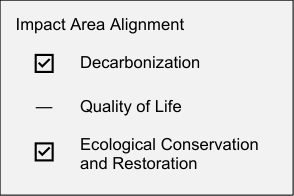
Water Efficiency Prerequisite
MINIMUM WATER EFFICIENCY
WEp1
REQUIRED
INTENT
To reduce potable water consumption and the associated energy consumption and carbon emissions required to treat and distribute water and preserve potable water resources through an efficiency-first approach.
REQUIREMENTS
| Achievement pathways | Points |
|---|---|
Commercial Interiors | N/A |
Minimum Fixture and Fittings Efficiency | |
Option 1. Prescriptive Path — Maximum Flush and Flow Rates | Option 1. Prescriptive Path — Maximum Flush and Flow Rates |
OR | OR |
Option 2. Performance Path — Calculated Reduction | Option 2. Performance Path — Calculated Reduction |
AND | AND |
Minimum Equipment Water Efficiency | Minimum Equipment Water Efficiency |
Meet all minimum water efficiency requirements outlined below, as applicable to the project scope.
Minimum Fixture and Fittings Efficiency
Meet the minimum water efficiency requirements for fixtures and fittings outlined below.
Projects located where standard supply pressure is different than the LEED baseline supply pressure may calculate the water consumption of flow fixtures and fittings at the local standard supply pressure.
OPTION 1. PRESCRIPTIVE PATH — MAXIMUM FLUSH AND FLOW RATES
For all new and existing fixtures and fittings within the tenant space, do not exceed the maximum flush and flow rates listed in Table 1.
U.S. Green Building Council LEED v5 Reference Guide for Interior Design and Construction, April 2025 Launch Edition 71
PDF Page 83
Table 1. Maximum installed flush or flow rates for prescriptive path
| Fixture or fitting | Maximum installed flush or flow rate (IP) | Maximum installed flush or flow rate (SI) |
|---|---|---|
| Toilet (water closet)* | 1.28 gpf** | 4.8 lpf** |
Urinal* | 0.50 gpf | 1.9 lpf |
Public lavatory (restroom) faucet | 0.50 gpm | 1.9 lpm |
Private lavatory faucets* | 1.50 gpm | 5.7 lpm |
Kitchen faucet | 1.8 gpm | 6.8 lpm |
Showerhead* | 2.00 gpm | 7.6 lpm |
*The WaterSense label is available for this fixture type. WaterSense-labeled fixtures are recommended for projects located in the U.S. and Canada.
**For dual-flush toilets, the full flush volume shall be equal to or less than 1.28 gpf / 4.8 lpf; a weighted average cannot be used.
OR
OPTION 2. PERFORMANCE PATH — CALCULATED REDUCTION
For all the new and existing fixtures and fittings within the tenant space, reduce aggregate water consumption by 20% from the baseline listed in Table 2.
Table 2. Baseline water consumption of fixtures and fittings
| Fixture or fitting | Baseline installed flush or flow rate (IP) | Baseline installed flush or flow rate (SI) |
|---|---|---|
| Toilet (water closet)* | 1.6 gpf** | 6.0 lpf |
Urinal* | 1.0 gpf | 3.8 lpf |
Public lavatory (restroom) faucet | 0.50 gpm at 60 psi | 1.9 lpm at 415 kPa |
Private lavatory faucets* | 2.2 gpm at 60 psi | 8.3 lpm at 415 kPa |
Kitchen faucet | 2.2 gpm at 60 psi | 8.3 lpm at 415 kPa |
Showerhead* | 2.5 gpm at 80 psi per shower stall | 9.5 lpm at 550 kPa per shower stall |
*The WaterSense label is available for this fixture type. WaterSense-labeled fixtures are recommended for projects located in the U.S. and Canada.
**For dual-flush toilets, the full flush volume shall be equal to or less than 1.28 gpf / 4.8 lpf; a weighted average cannot be used.
AND
Minimum Equipment Water Efficiency
Newly installed appliances, equipment, and processes within the tenant space must meet the requirements listed in Tables 3 and 4 below. Existing appliances and equipment can be excluded.
U.S. Green Building Council LEED v5 Reference Guide for Interior Design and Construction, April 2025 Launch Edition 72
PDF Page 84
Table 3. Standards for appliances
| Appliance | Col2 | Requirement | Col4 |
|---|---|---|---|
| Residential clothes washer | Residential clothes washer | ENERGY STAR® or performance equivalent | ENERGY STAR® or performance equivalent |
| Commercial clothes washer | Commercial clothes washer | ENERGY STAR® for commercial clothes washers with ≤ 8.0 cubic feet (227 liters) of capacity or performance equivalent | ENERGY STAR® for commercial clothes washers with ≤ 8.0 cubic feet (227 liters) of capacity or performance equivalent |
| Residential dishwashers (standard and compact) | Residential dishwashers (standard and compact) | ENERGY STAR® or performance equivalent | ENERGY STAR® or performance equivalent |
| Prerinse spray valves | Prerinse spray valves | ≤ 1.3 gpm (4.9 lpm) | ≤ 1.3 gpm (4.9 lpm) |
| Ice machine | Ice machine | ENERGY STAR® or performance equivalent and use either air-cooled or closed-loop cooling, such as chilled or condenser water system | ENERGY STAR® or performance equivalent and use either air-cooled or closed-loop cooling, such as chilled or condenser water system |
| Commercial Kitchen Equipment | Commercial Kitchen Equipment | Requirement (IP) | Requirement (SI) |
| Dishwasher | Undercounter | ≤ 1.6 gal/rack | ≤ 6.0 liters/rack |
| Dishwasher | Stationary, single tank, door | ≤ 1.4 gal/rack | ≤ 5.3 liters/rack |
| Dishwasher | Single tank, conveyor | ≤ 1.0 gal/rack | ≤ 3.8 liters/rack |
| Dishwasher | Multiple tank, conveyor | ≤ 0.9 gal/rack | ≤ 3.4 liters/rack |
| Dishwasher | Flight machine | ≤ 180 gal/hr | ≤ 680 liters/hr |
| Food steamer | Boilerless/ connectionless | ≤ 2 gal/hr/pan | ≤ 7.5 liters/hr/pan |
| Food steamer | Steam generator | ≤ 5 gal/hr/pan | ≤ 19 liters/hr/pan |
| Combination oven | Countertop or stand | ≤ 1.5 gal/pan | ≤ 5.7 liters/pan |
| Combination oven | Roll-in | ≤ 1.5 gal/pan | ≤ 5.7 liters/pan |
Table 4. Standards for processes
| Process | Requirement |
|---|---|
| Heat rejection and cooling | No once-through cooling with potable water for any equipment or appliances that reject heat |
| Discharge water temperature tempering | Where local requirements limit the discharge temperature of fluids into a drainage system, use a tempering device that runs water only when the equipment discharges hot water. OR Provide a thermal recovery heat exchanger that cools drained discharge water below code-required maximum discharge temperatures while simultaneously preheating inlet makeup water. OR If fluid is steam condensate, return it to boiler. |
| Venturi-type flow-through vacuum generators or aspirators | Use no device that generates a vacuum by means of water flow through the device into the drain. |
U.S. Green Building Council LEED v5 Reference Guide for Interior Design and Construction, April 2025 Launch Edition 73
PDF Page 85
REQUIREMENTS EXPLAINED
This prerequisite identifies minimum water efficiency requirements for fixtures, fittings, appliances, and process water. Two compliance options exist for fixture and fitting efficiency.
Minimum Fixture and Fitting Efficiency
Reducing potable water use for fixtures and fittings begins with conservation efforts. Selecting high-efficiency fixtures reduces water consumption and demand. The selection of high efficiency fixtures can lead to savings from reductions in pump energy and water heating requirements. For example, selecting these fixtures for lavatories, faucets, and showerheads reduces the electrical load required for water heating.
Choose either a prescriptive or performance pathway to demonstrate compliance for fixture and fitting efficiencies.
OPTION 1. PRESCRIPTIVE PATH — MAXIMUM FLUSH AND FLOW RATES
The prescriptive path offers a streamlined approach for the prerequisite. Table 1 outlines the maximum allowable flush or flow rate for fixtures and fittings within the project boundary. All fixtures and fittings installed must not exceed these maximum values.
For projects that install dual-flush toilets, the volume of the full flush must be used when calculating flush rate. The full-flush rate must not exceed 1.28 gallons per flush (gpf) (4.8 liters per flush (lpf)). Projects cannot use a fixture with a weighted average flow of 1.28 gpf (4.8 lpf).
Teams conducting projects in the U.S. and Canada are encouraged to use WaterSense-labeled toilets (water closets), urinals, private lavatory faucets, and showerheads. WaterSense-labeled products require testing and verification for efficiency by third-party vendors. These products comply with U.S. Environmental Protection Agency (U.S. EPA) specifications.
OPTION 2. PERFORMANCE PATH — CALCULATED REDUCTION
Using the performance-based approach, teams can maximize water conservation across all applicable fixtures and fittings within the project boundary. Teams pursuing points under WEc2: Enhanced Water Efficiency should consider Option 2. Performance Path — Calculated Reduction to show prerequisite compliance. Compliance with WEp1: Minimum Water Efficiency, Option 2. Performance Path — Calculated Reduction and WEc2: Enhanced Water Efficiency, Option 2. Fixture and Fittings — Calculated Reduction requires documented compliance through the USGBC-approved calculator.
U.S. Green Building Council LEED v5 Reference Guide for Interior Design and Construction, April 2025 Launch Edition 74
PDF Page 86
Teams must prove a 20% reduction from the baseline water use to meet the minimum prerequisite requirements.
Determining the baseline and design case water use Teams must determine the project’s baseline water consumption. Total annual consumption depends on project-specific data, including fitting and fixture types, flush and flow rates, the number of full-time equivalents and visitors, annual days of operation, and gender ratios. This data must remain consistent across all LEED ID+C: Commercial Interiors credits, to maintain the integrity of the submission.
The total number of uses for each fixture and fitting remains the same in the baseline and design case calculations. The baseline flush and flow rates must use values from Table 2, which represent the maximum allowed flush and flow rates. The design case must use designed values that represent the fixtures and fittings installed in the project. For projects that have dualflush toilets, use the full-flush volume in the design case calculations. Do not use the weighted average.
Develop calculations using the USGBC-approved calculator for this option to determine the percent reduction.
AND
Minimum Equipment Water Efficiency
During design, teams must identify appliances, kitchen equipment, and processes within the project boundary and specify products that meet the requirements of Tables 3 and 4. Projects in the U.S. and Canada must use ENERGY STAR®-labeled equipment. For international projects, a performance-based equivalent meets the requirement.
ENERGY STAR® - qualified appliances perform better than conventional appliances. For example, ENERGY STAR® washing machines and dishwashers use 30% and 18% less water, respectively, than their conventional counterparts. These appliances also consume 10% to 50% less energy than conventional appliances. [26] Commercial kitchens employ processes that use a high level of energy and water, such as dishwashing and food preparation.
26 “Guide to home water efficiency”, U.S. Department of Energy, accessed March 31, 2025, https://www.energy.gov/sites/prod/files/guide_to_home_water_efficiency.pdf.
U.S. Green Building Council LEED v5 Reference Guide for Interior Design and Construction, April 2025 Launch Edition 75
PDF Page 87
DOCUMENTATION
| Project types | Options | Paths | Documentation |
|---|---|---|---|
| All | All | All | Contract document(s) specifying the project’s commercial kitchen equipment water use, including performance specifications. |
| All | All | All | Contract document(s) specifying the project’s process water equipment, including performance specifications. |
| All | All | All | Contract document(s) specifying the project’s appliances, equipment, and process water equipment, including performance specifications. |
| All | All | All | Contract document(s) specifying the project’s plumbing fixtures and fittings, including performance specifications. |
| All | All | All | LEED v5 Fixture and Fittings Efficiency calculator, documenting the fixtures/fittings within the tenant space and the occupants who use them. |
REFERENCED STANDARDS
U.S. Green Building Council LEED v5 Reference Guide for Interior Design and Construction, April 2025 Launch Edition 76
PDF Page 88
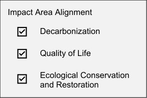
Water Efficiency Credit
WATER METERING AND LEAK DETECTION
WEc1
1–2 points
INTENT
To conserve potable water resources, support water management, limit potential material waste due to water leak damage, and identify opportunities for additional water savings by tracking water consumption.
REQUIREMENTS
| Achievement pathways | Points |
|---|---|
Commercial Interiors | 1–2 |
Option 1. Meters | 1 |
AND/OR | |
Option 2. Submeters | 1 |
AND/OR | |
Option 3. Leak Detection Sensors | 1 |
Option 1. Meters (1 point)
Install (or use existing) permanent water meters or submeters that measure the total water consumption for each water source for the tenant space that meet the following requirements:
-
The tenant must be able to access the meter data.
-
Meter alternative water sources separately from municipally supplied potable water.
-
Commit to sharing with USGBC the resulting tenant space water usage data at least annually. This commitment must carry forward for five years or until the building changes ownership or lessee.
AND/OR
Option 2. Submeters (1 point)
Install permanent water submeters for each applicable subsystem defined below:
- Indoor plumbing fixtures and fittings with meter systems serving at least 80% of indoor fixtures and fittings as described in WEp1: Minimum Water Efficiency and fixtures and fittings not addressed in the prerequisite, including janitor sinks, water coolers, and bottle fillers, which may be included or excluded from the measured total water consumption of the tenant space at the project team’s discretion.
U.S. Green Building Council LEED v5 Reference Guide for Interior Design and Construction, April 2025 Launch Edition 77
PDF Page 89
-
Commercial kitchen (if the kitchen serves at least 100 meals per day of operation)
- Laundry, if the project includes commercial laundry equipment that processes at least 120,000 lbs. (57,606 kg.) of laundry per year or if the project includes a public laundry room)
The tenant must be able to access the submeter data in real time via local network, building management system (BMS), cloud service, app, or online database. All submeters must be capable of recording data at least hourly.
AND/OR
Option 3. Leak Detection Sensors (1 point)
Install permanent water flow meter/sensors for at least 50% of the project flush fixtures in the tenant space; water sensors can be installed on each flush fixture or for a group of flush fixtures (e.g., one per restroom facility).
The leak detection system should be able to identify a leak triggered by abnormal flow rate above normal range, or physically detect a water leak, and initiate an alarm upon a leak detection.
The tenant must be able to access the sensor data in real time via local network, BMS, cloud service, app, or online database.
Develop an action plan that addresses how the tenant will have access to data in real time and how the tenant will address and remedy any detected leak.
REQUIREMENTS EXPLAINED
The credit encourages projects to develop water metering and submetering strategies. Projects pursuing this credit must install permanent water meters or have access to data from existing meters, submeters, and sensors necessary to report and track water use for applicable subsystems.
Option 1 requires permanent meters or submeters on all water-using systems within the tenant spaces. Option 2 requires the use of permanent meters or submeters for applicable subsystems. Option 3 requires installation of permanent leak detection sensors and data integration with the BMS or similar.
Submetering and leak detection strategies, when developed early in the design, provide significant benefits to the owner and design team. Teams can identify all water-using systems and prioritize submeters on major systems. Reviewing the systems during the schematic or
U.S. Green Building Council LEED v5 Reference Guide for Interior Design and Construction, April 2025 Launch Edition 78
PDF Page 90
design phase allows for design optimizations including, but not limited to, meter placement, water heater or boiler room locations, and distribution piping design.
Projects can achieve up to two points by combining a minimum of two of the three options. o
Option 1. Meters
Option 1 requires that projects install meters or utilize existing meters to collect water consumption data (gallons or liters) from all water sources within the tenant space. This includes potable and alternative water. Teams must report total project water consumption to USGBC at minimum annually. The data must also be accessible to the tenant and/or other appropriate person(s).
Tracking and reviewing data monthly allow tenants an ongoing opportunity to identify inefficiencies or anomalies in consumption. The data review also immediately addresses problems, such as leaks and failed valves, before larger issues or excess consumption occur.
Identifying all water sources and water end uses Project teams must identify all water end uses in the tenant spaces and analyze water consumption from each source. Common water sources include plumbing fixtures, cooling towers, laundry facilities, dishwashers, indoor water features, and other building processes.
Identify the water source for each end use. Potable water sources include public water supply, on-site wells, and on-site potable water treatment systems. Alternative water sources include greywater, rainwater, recycled water, and reclaimed water. Alternative water sources must be metered separately from municipally supplied potable water.
Meters and types of meters Install meters only for systems within the scope of work. Specify permanent meter(s) that provide water consumption data in gallons or liters. A utility-owned meter that provides the required data meets the prerequisite requirements. Utility providers often read and bill total water consumption monthly.
Tracking and reporting Demonstrate that the key person(s) responsible for tracking and reporting water consumption data can access the meter. If the location is inaccessible, providing access to monthly utility bill(s) achieves the same goal. If projects cannot demonstrate access through direct, visual readings or monthly utility bills, teams must install additional meter(s) to meet the prerequisite.
U.S. Green Building Council LEED v5 Reference Guide for Interior Design and Construction, April 2025 Launch Edition 79
PDF Page 91
Multiple sources of potable or alternative water in a project boundary Teams must identify if multiple sources of potable water or alternative water are used within the project boundary. A single meter per water source can meet the requirement if the design allows for the proper placement of the meter.
Commitment to sharing data with USGBC USGBC aims to collect data on water usage from all LEED ID+C projects. Having this data allows USGBC to identify similarities between high-performing projects and recommend solutions with proven results.
Projects must commit to reporting the total water consumption to USGBC at least annually. Data must be shared for five years or until the building changes ownership or lessee. Share data using a USGBC-approved data template or an approved third-party data source, like ENERGY STAR® Portfolio Manager.
Option 2. Submeters
Teams must install submeters for indoor plumbing fixtures and fittings, commercial kitchen water use, and laundry water use.
Facility managers and/or tenants must have access to the real-time data via the project’s local network, BMS, cloud service, web-based application, or an online database.
Indoor plumbing fixtures and fittings Most projects have indoor plumbing fixtures and fittings. Water use from water closets and lavatories represents a significant amount of a building’s total water consumption for many project types. Additionally, leaks from indoor fixtures and fittings often go unnoticed until water damage occurs on walls, ceilings, or floors.
Projects must submeter at least 80% of the total indoor fixtures and fittings, as identified in WEp1: Minimum Water Efficiency .
Depending on the distribution piping and the metering strategy, projects can directly meter water consumption from indoor plumbing fixtures and fittings or calculate the consumption by subtracting all other subsystems from the total water consumption on the building and the grounds.
Commercial kitchens Typical commercial kitchen systems such as dishwashers, food steamers, and combination ovens require large quantities of potable water. Even when using water-efficient equipment, it is
U.S. Green Building Council LEED v5 Reference Guide for Interior Design and Construction, April 2025 Launch Edition 80
PDF Page 92
critical that projects track consumption from these appliances to ensure efficient operations and identify water-supply failures.
The requirement for metering water use in a commercial kitchen depends on the number of daily meals served. Kitchens designed to serve 100 or more daily meals must meter and report all water use from kitchen operations.
Public laundry facilities Typical commercial laundry systems include large top- or front-load washing machines used to process thousands of pounds (or kilograms) of laundry annually. Front-load washers use less water and energy than top-load washers. However, even when using ENERGY STAR®® (or performance-equivalent) equipment, it is critical that projects track water consumption from these machines to ensure efficient operations and identify water-supply failures.
The requirement for metering water use in a commercial laundry depends on the pounds (or kilograms) of laundry processed annually. Laundry facilities designed to process 120,000 lbs. (57,606 kg.) of laundry annually must meter and report all water use from the laundry operations.
Option 3. Leak Detection Sensors
Water lost through leaks strains capital and natural resources while creating health and safety risks. [27] Lower system pressures can allow pollutants to be drawn in from the surroundings, leading to foul drinking water. [28] Capital losses can result from labor costs to identify a leak’s location as well as from labor hours and material costs necessary to repair major damage. Leaks that are not addressed commonly cause higher bills.
Projects pursuing this option must install permanent water flow meters or sensors for all flush fixtures within the project boundary. The devices must report abnormalities and generate an alarm at a local network, BMS, cloud service, app, or online database accessible by the facility manager and tenants.
Data access and action plan Providing access to data and regularly performing reviews optimizes an operator’s ability to address water leaks. Develop an action plan that addresses, at minimum, data access for
27 “Overview of Available Leak Detection Technologies”, Pacific Northwest National Laboratory, (2019), retrieved from https://www.pnnl.gov/main/publications/external/technical_reports/PNNL-28885.pdf. 28 R. Collins, J. Boxall, M. Besner, S. Beck and B. Karney, “Intrusion Modelling and the Effect of Ground Water Conditions”, Water Distribution Systems Analysis 2010, (2011).
U.S. Green Building Council LEED v5 Reference Guide for Interior Design and Construction, April 2025 Launch Edition 81
PDF Page 93
operators and tenants, the approach for resolving detected leaks, and a communication plan to alert building occupants when repairs impact the building.
Flush fixture leak detection requirements For the flush fixtures, install sensors or meters for at least 50% of the flush fixtures identified in WEp1: Minimum Water Efficiency . Install the device at the flush fixture for an individual toilet room, such as a unisex or family restroom. A single device that monitors all flush fixtures for group restrooms is acceptable.
DOCUMENTATION
| Project types | Options | Paths | Documentation |
|---|---|---|---|
All | Option 1. Meters | All | Contract documents highlighting the locations and types of the project’s permanent water meters or submeters that measure the total water consumption for each water source for the tenant space (for example, water supply system drawings). |
All | Option 1. Meters | All | Commitment from the project owner to share with USGBC the resulting tenant space water usage data at least annually. |
All | Option 1. Meters | All | Confirmation that the data is accessible by the tenant. |
| All | Option 2. Submeters | All | Confirmation that all submeters are capable of recording data at least hourly (for example, product information from the manufacturer and/or contract documents). |
| All | Option 2. Submeters | All | Contract documents highlighting the locations and types of the project’s permanent water meters for each applicable subsystem (for example, water supply system drawings). |
| All | Option 2. Submeters | All | Contract documents demonstrating that facility manager and/or tenant(s) will be able to access the submeter data in real-time via local network, BMS, cloud service, app, or online database, and that all submeters are capable of recording data at least hourly. |
| All | Option 2. Submeters | All | Calculation demonstrating the percentage of metered indoor fixtures/fittings. |
| All | Option 3. Leak Detection Sensors | All | Contract documents highlighting the locations and types of the project’s permanent water flow meters/sensors for the project’s flush fixtures in the tenant space (for example, water supply system drawings). |
| All | Option 3. Leak Detection Sensors | All | Narrative or documents detailing the leak detection system specifications, for when and how an alarm is triggered (for example, the Owner’s Project Requirements, BOD, Contract Documents, or product information from the manufacturer) |
| All | Option 3. Leak Detection Sensors | All | The project’s action plan that addresses how the tenant will have access to data in real-time and will address and remedy any detected leak. |
| All | Option 3. Leak Detection Sensors | All | Calculation demonstrating the percentage of flush fixtures with leak detection. |
U.S. Green Building Council LEED v5 Reference Guide for Interior Design and Construction, April 2025 Launch Edition 82
PDF Page 94
REFERENCED STANDARDS
- None
U.S. Green Building Council LEED v5 Reference Guide for Interior Design and Construction, April 2025 Launch Edition 83
PDF Page 95
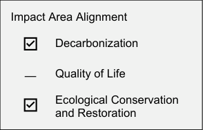
Water Efficiency Credit
ENHANCED WATER EFFICIENCY
WEc2
1–8 points
INTENT
To reduce potable water consumption and the associated energy consumption and carbon emissions required to treat and distribute water and to reward the use of alternative water sources that preserve potable water resources.
REQUIREMENTS
| Achievement pathways | Points |
|---|---|
Commercial Interiors | 1–8 |
Option 1. Whole-Project Water Use | 1–8 |
OR | |
Option 2. Fixture and Fittings — Calculated Reduction | 1–6 |
AND/OR | |
Option 3. Appliance and Process Water | 1–2 |
AND/OR | |
Option 4. Optimize Process Water Use | 1–2 |
Path 1. Limit Cooling Tower Cycles | 1–2 |
OR | |
Path 2. Optimize Water Use for Cooling | 1–2 |
OR | |
Path 3. Process Water Use | 1–2 |
Implement a combination of the strategies below for a maximum of 8 points. Projects may either attempt Option 1 or any combination of Options 2 or 3 below.
Option 1. Whole-Project Water Use (1–8 points)
To pursue this pathway, project teams must develop a water use baseline and create a proposed use model. Points are achieved based on reductions from the baseline in Table 1.
Table 1. Points for reducing overall project water use
| Percent reduction | Points | Total points for alternative water |
|---|---|---|
30% | 1 | 2 |
35% | 2 | 3 |
40% | 3 | 4 |
45% | 4 | 5 |
50% | 5 | 6 |
55% | 6 | 7 |
U.S. Green Building Council LEED v5 Reference Guide for Interior Design and Construction, April 2025 Launch Edition 84
PDF Page 96
| Percent reduction | Points | Total points for alternative water |
|---|---|---|
60% | 7 | 8 |
65% | 8 | 0 |
OR
Option 2. Fixture and Fittings — Calculated Reduction (1–6 points)
Further reduce fixture and fitting water use from the calculated baseline in WEp1: Minimum Water Efficiency, Minimum Fixture and Fittings Efficiency, Option 2, Performance Path– Calculated Reduction. Some of these fittings and fixtures may be outside the tenant space. Additional potable water savings can be earned above the prerequisite level using alternative water sources. Points are awarded according to Table 2.
Table 2. Points for reducing indoor water use
| Percentage reduction | Points |
|---|---|
25% | 1 |
30% | 2 |
35% | 3 |
40% | 4 |
45% | 5 |
50% | 6 |
AND/OR
Option 3. Appliance and Process Water (1–2 points)
Newly installed equipment within the tenant space must meet the minimum requirements in Tables 3, 4, and/or 5. 1 point is awarded for meeting all applicable requirements in any one table for a maximum of 2 points. All applicable, newly installed equipment listed in each table must meet the standard. Existing appliances and equipment can be excluded.
To use Table 3, the project must process at least 120,000 lbs. (57,606 kg.) of laundry per year.
Table 3. Compliant commercial washing machines
| Washing machine | Requirement (IP units) | Requirement (SI units) |
|---|---|---|
| On-premise, minimum capacity 2,400 lbs. (10,886 kg.) per 8-hour shift | Maximum 1.8 gallons per pound* | Maximum 7 liters per 0.45 kilogram* |
To use Table 4, the project must serve at least 100 meals per day of operation.
Table 4. Standards for compliant commercial kitchen equipment
| Commercial Kitchen Equipment | Col2 | Requirement (IP) | Requirement (SI) |
|---|---|---|---|
| Dishwasher | Undercounter | ENERGY STAR® | ENERGY STAR® or performance equivalent |
U.S. Green Building Council LEED v5 Reference Guide for Interior Design and Construction, April 2025 Launch Edition 85
PDF Page 97
| Commercial Kitchen Equipment | Col2 | Requirement (IP) | Requirement (SI) |
|---|---|---|---|
| Stationary, single tank, door | ENERGY STAR® | ENERGY STAR® or performance equivalent | |
| Single tank, conveyor | ENERGY STAR® | ENERGY STAR® or performance equivalent | |
| Multiple tank, conveyor | ENERGY STAR® | ENERGY STAR® or performance equivalent | |
| Flight machine | ENERGY STAR® | ENERGY STAR® or performance equivalent | |
| Food steamer | Boilerless/ connectionless | ≤ 1.7 gal/hr/pan including condensate cooling water | ≤ 6.4 liters/hr/pan including condensate cooling water |
| Food steamer | Steam generator | ≤ 2.2 gal/hr/pan including condensate cooling water | ≤ 8.3 liters/hr/pan including condensate cooling water |
| Combination oven | Countertop or stand | ENERGY STAR® | ENERGY STAR® or performance equivalent |
| Combination oven | Roll-in | ENERGY STAR® | ENERGY STAR® or performance equivalent |
| Food waste disposer | Disposer | 3–8 gpm, full-load condition; 10-minute automatic shutoff or 1 gpm, no-load condition | 11–30 lpm, full-load condition; 10-minute automatic shutoff or 3.8 lpm, no-load condition |
| Food waste disposer | Scrap collector | Maximum 2 gpm makeup water | Maximum 7.6 lpm makeup water |
| Food waste disposer | Pulper | Maximum 2 gpm makeup water | Maximum 7.6 lpm makeup water |
| Food waste disposer | Strainer basket | No additional water usage | No additional water usage |
Table 5. Compliant laboratory and medical equipment
| Lab equipment | Requirement (IP) | Requirement (SI) |
|---|---|---|
| Reverse-osmosis water purifier | 75% recovery | 75% recovery |
| Steam sterilizer | For 60-in sterilizer: 6.3 gal/U.S. tray For 48-in sterilizer: 7.5 gal/U.S. tray | For 1,520-mm sterilizer: 28.5 liters/DIN tray For 1,220-mm sterilizer: 28.35 liters/DIN tray |
| Sterile process washer | 0.35 gal/U.S. tray | 1.3 liters/DIN tray |
| X-ray processor, 150 mm or more in any dimension | Film processor water recycling unit | Film processor water recycling unit |
Digital imager, all sizes | No water use | No water use |
AND/OR
Option 4. Optimize Process Water Use (1–2 points)
Include any associated base building water use that is necessary for equipment that serves the tenant space.
U.S. Green Building Council LEED v5 Reference Guide for Interior Design and Construction, April 2025 Launch Edition 86
PDF Page 98
PATH 1. LIMIT COOLING TOWER CYCLES (1–2 POINTS)
For cooling towers and evaporative condensers, conduct a one-time potable water analysis, measuring at least the five control parameters listed in Table 6.
Table 6. Maximum concentrations for parameters in condenser
| Parameter | Maximum level |
|---|---|
| Ca (as CaCO3) | 600 ppm |
| Total alkalinity | 500 ppm |
| SiO2 | 150 ppm |
| Cl– | 300 ppm |
| Conductivity | 3,300 μS/cm |
NOTE: ppm = parts per million
NOTE: µS/cm = micro siemens per centimeter
Calculate the maximum number of cooling tower cycles by dividing the maximum allowed concentration level of each parameter by the actual concentration level of each parameter found in the potable makeup water analysis. Limit cooling tower cycles to avoid exceeding maximum values for any of these parameters.
The materials of construction for the water system that come in contact with the cooling tower water shall be of the type that can operate and be maintained within the cycles established in Table 7.
Table 7. Points for cooling tower cycles
| Cooling tower cycles | Points |
|---|---|
| Maximum number of cycles achieved without exceeding any maximum concentration levels or affecting operation of condenser water system. | 1 |
| Meet the maximum calculated number of cycles to earn 1 point and increase the number of cycles by a minimum of 25% by increasing the level of treatment and/or maintenance in condenser or makeup water systems. OR Meet the maximum calculated number of cycles to earn 1 point and use a minimum of 20% alternative water. | 2 |
Projects whose cooling is provided by district cooling systems are eligible to achieve Path 1 if the district cooling system complies with the above requirements.
OR
U.S. Green Building Council LEED v5 Reference Guide for Interior Design and Construction, April 2025 Launch Edition 87
PDF Page 99
PATH 2. OPTIMIZE WATER USE FOR COOLING (1–2 POINTS)
To be eligible for Option 2, the baseline system designated for a building using ASHRAE 90.1- 2019 or 90.1-2022, Appendix G, Table G3.1, 1–3 must include a cooling tower (systems 7, 8, 11, 12, and 13).
Achieve increasing levels of cooling tower water efficiency beyond a water-cooled chiller system with axial variable-speed fan cooling towers having a maximum drift of 0.002% of recirculated water volume and three cooling tower cycles. Points are awarded according to Table 8.
Table 8. Points for reducing annual water use compared to water-cooled chiller system
| Percentage reduction | Points |
|---|---|
| 25% | 1 |
| 50% | 2 |
Projects whose cooling is provided by district cooling systems are eligible to achieve Path 2 if the district cooling system complies with the above requirements.
OR
PATH 3. PROCESS WATER USE (1–2 POINTS)
Demonstrate that the project is using a minimum of 20% alternative water to meet the process water demand for 1 point or using a minimum of 30% alternative water to meet the process water demand for two points. Ensure that alternative water is of sufficient quality for its intended end use.
The minimum percentage of alternative water used should be based on water use during the month with the highest water demand.
Process water uses eligible for achievement of Path 3 must represent at least 10% of total building regulated water use and may not include water used for cooling.
REQUIREMENTS EXPLAINED
The credit builds on WEp1: Minimum Water Efficiency and rewards teams for additional water conservation strategies. Projects that pursue Option 1 can achieve up to eight points for the whole project water use reductions. Projects that pursue Options 2–4 can achieve up to eight points by combining any of the strategies outlined in the rating system.
Projects cannot combine Option 1 with Options 2–4.
U.S. Green Building Council LEED v5 Reference Guide for Interior Design and Construction, April 2025 Launch Edition 88
PDF Page 100
Option 1. Whole Project Water Use
Quantifying whole project water use and developing strategies to reduce consumption across the entire project can lead to significant water savings. Analyzing all water sources enables teams to identify large consumers and target both conservation and alternative water strategies.
Projects must demonstrate a minimum of 30% reduction from the project’s baseline to earn points. Using alternative water sources earns additional points for the calculated reductions.
Develop a water balance model Teams must calculate the building’s water demand and develop baseline and design case water balance models. Models must account for all water sources within the project’s scope of work, including fixtures and fittings, domestic hot water, appliances, commercial kitchen and laundry equipment, laboratory and medical equipment, process water, and HVAC systems.
BASELINE REQUIREMENTS The baseline model reflects the minimum requirements and typical water use for the project type without any additional water-savings measures.
For fixtures and fittings, determine the baseline using a USGBC-approved calculator, as described in WEp1: Minimum Water Efficiency, Option 2. Performance Path — Calculated Reduction.
Baseline values for appliances, kitchen equipment, and laboratory and medical equipment must align with Tables 3–5 of this credit.
For cooling towers, the baseline water model represents the water use associated with the minimum number of cooling tower cycles, such that parameters do not exceed the values of Table 6.
DESIGN CASE REQUIREMENTS The design-case water model must use fixtures and fittings, appliances, kitchen equipment, and laboratory and medical equipment as specified within the contract documents.
Projects with alternative water sources Use of alternative water sources can be highly effective in reducing potable water demand and utility costs associated with the building. Projects that use alternative water sources achieve 1 additional point for each threshold met under Table 1. For example, a project that reduces potable water consumption by 30% earns 1 point. A project that reduces potable water
U.S. Green Building Council LEED v5 Reference Guide for Interior Design and Construction, April 2025 Launch Edition 89
PDF Page 101
consumption by 30% and uses an alternative water source to achieve those reductions earn two points.
Projects should always prioritize water efficiency first to reduce consumption and demand before applying alternative water solutions. For any seasonally dependent sources, such as rainwater, calculations must reflect annual, seasonal totals to confirm the available quantity of the alternative water source.
Projects pursuing Options 2–4 Projects may earn up to eight points by combining strategies from Options 2–4. Projects with limited scope or projects that use targeted reductions by equipment or system type, should review Option 1 and all relevant Options 2–4 to determine the approach that maximizes points for this credit.
Option 2. Fixtures and Fittings — Calculated Reduction
Option 2 focuses on reducing potable water use from fixtures and fittings. Using the baseline and designed water usage calculations determined from WEp1: Minimum Water Efficiency, Minimum Fixture and Fittings Efficiency, Path 2: Performance Path – Calculated Reduction, projects earn points for additional savings beyond the 20% requirement, based on specific fixture flow and flush rates. Savings must be calculated using a USGBC-approved calculator. Projects achieving a 25% reduction earn one point.
Along with the use of high-efficiency fixtures and fittings, projects that use alternative water sources for these systems can report further savings and achieve additional points under this option.
AND/OR
Option 3. Appliance and Process Water
Option 3 rewards projects that prioritize water-efficient appliances and process equipment. Projects earn one point for meeting prescriptive water use requirements in a single equipment category, for up to two total points.
Tables 3–5 outline the prescriptive measures for appliances and process equipment. All newly installed equipment must meet the referenced standards, performance equivalents (outside of the U.S.), and/or water use limits. Existing appliances and equipment should be excluded.
Projects that do not include any applicable systems in their scope of work or projects that can document compliance with more than two tables, should review the whole project’s water
U.S. Green Building Council LEED v5 Reference Guide for Interior Design and Construction, April 2025 Launch Edition 90
PDF Page 102
balance model from WEc2: Enhanced Water Efficiency, Option 1. Whole Project Water Use, as it may optimize points for this credit.
AND/OR
Option 4. Optimize Process Water Use
Cooling towers and industrial processes use a significant amount of potable water. Projects that include these systems must consider opportunities to reduce cycles of concentration, optimize water use for cooling, or select alternative water sources.
Process water uses include, but are not limited to, cooling, humidification, sterilization, dishwashers, clothes washers, and pools. This option offers three pathways, which depend on the type of process water use. Path 3 also requires that process water use meets a minimum percentage of the total building water use.
PATH 1. LIMIT COOLING TOWER CYCLES
This path prioritizes water conservation for cooling towers by limiting the cycles of concentration from the equipment. A cycle of concentration is the number of times water can circulate through the system without creating performance or operational problems. A low cycle of concentration means more single-use water passes through the system, resulting in excess water consumption. However, as water is reused, dissolved solids remain, which increases the concentration levels of calcium, silicon dioxide (SiO2), and chloride. Higher cycles of concentration may result in scaling and corrosion issues.
The intent of the credit is not to impact system operations, but to inform designers on alternative solutions for reducing water consumption for cooling processes. Finding the correct balance of cooling tower blowdown and chemical treatment maintains system efficiency, reduces maintenance, and conserves potable water.
For each cooling process, conduct a potable water analysis to determine setpoints for the chemical treatment system and the associated cycles of concentration. Teams must confirm that the systems will operate at the specified cycles of concentration and not exceed parameters outlined in Table 6.
Projects with alternative water sources Projects using alternative water sources do not require one-time water analysis. Using a minimum of 20% alternative water can help projects earn two points, if the maximum calculated number of cycles is also met.
U.S. Green Building Council LEED v5 Reference Guide for Interior Design and Construction, April 2025 Launch Edition 91
PDF Page 103
Projects in a campus environment Projects in a campus environment or those supplied by a district cooling system, may comply with Path 1 if the district system conducts a potable water analysis and limits the cycles of concentration for their system. Projects can determine compliance at the district level by working with the utility provider.
PATH 2. OPTIMIZE WATER USE FOR COOLING
Path 2 has minimum eligibility requirements. Using ASHRAE Standard 90.1-2019 (or later), Appendix G Performance Rating Method, Table G3.1.1-2, confirm that the project’s baseline case includes CHW for cooling and cooling towers in the baseline design. Table 9 outlines the eligible baseline systems from Appendix G.
Projects pursuing this path do not require an Appendix G energy model. Other tools can be used to perform water use calculations.
Table 9. ASHRAE Standard 90.1-2019, Appendix G compliant baseline systems
| System number | System description |
|---|---|
| 7 | VAV with reheat |
| 8 | VAV with parallel fan-powered boxes and reheat |
| 11 | Single-zone VAV system with water-cooled chillers |
| 12 | Single-zone constant volume system with water-cooled chillers and a hot-water fossil fuel boiler |
| 13 | Single-zone constant volume system with water-cooled chillers and electric resistance heat |
Projects can demonstrate a 100% reduction from baseline if the Appendix G baseline includes a cooling tower and the final design eliminates the need for a cooling tower.
Projects may benefit from a combination of strategies to reduce water consumption for the cooling system. Strategies include maximizing cycles of concentration, increased levels of chemical treatment, smart controls for monitoring and optimization, drift eliminators, flow meters, and water level controls.
Projects in a campus environment For campus environments or projects that receive cooling from a district cooling system, projects meet the requirements of Path 2 if the district system meets the reduction thresholds. Projects should consider working with their utility provider to determine compliance at the district system level.
U.S. Green Building Council LEED v5 Reference Guide for Interior Design and Construction, April 2025 Launch Edition 92
PDF Page 104
PATH 3. PROCESS WATER USE
Projects pursuing this path must demonstrate that process water exceeds 10% of the total building-regulated water use, excluding cooling water.
Using alternative water sources, such as captured condensate from air handling units, reduces reliance on fresh water for process systems. Diversifying the water sources on a project site also builds resilience in buildings. This allows projects to divert freshwater for human consumption instead of processes during a water crisis.
When selecting the alternative water source, ensure that the quality of the water is sufficient for its intended use and that the local authority having jurisdiction (AHJ) allows that alternative water source, per local codes and standards.
DOCUMENTATION
| Project types | Options | Paths | Documentation |
|---|---|---|---|
| All | Option 1. Whole Project Water Use | All | LEED v5 Whole Project Water Use calculator. |
| All | Option 1. Whole Project Water Use | All | Contract documents and manufacturer information to support the baseline and proposed water use values in the calculator. |
| All | Option 2. Fixtures and Fittings | All | LEED v5 Fixture and Fittings Efficiency calculator, documenting the fixtures/fittings within and outside of the tenant space. If there are fixtures both within and outside the tenant space, this will be a separate, additional calculator from that submitted for the prerequisite. |
| All | Option 2. Fixtures and Fittings | All | Evidence of any plumbing fixtures and fittings used by the project occupants outside of the tenant space, including flush/flow rates (recommended: product information from the manufacturer, photographs with date/time/location stamp, and/or as-built documents). |
| All | Option 3. Appliance and Process Water | All | Contract document(s) specifying the project’s newly installed commercial washing machines, commercial food waste disposers, commercial laboratory and medical equipment, and/or municipal steam systems and process water equipment, as applicable, including performance specifications. |
| All | Option 4. Optimize Process Water Use | Path 1. Limit Cooling Tower Cycles | Results from the potable water analysis for cooling towers and evaporative condensers. Include the concentration levels for all five parameters listed in Table 8 of the rating system. |
| All | Option 4. Optimize Process Water Use | Path 2. Optimize Water Use for Cooling | Equipment schedule indicating cooling tower type. |
| All | Option 4. Optimize Process Water Use | Path 2. Optimize Water Use for Cooling | Calculation showing the baseline process water use. |
| All | Option 4. Optimize Process Water Use | Path 2. Optimize Water Use for Cooling | Calculation showing the design process water use, including any alternative water savings. |
U.S. Green Building Council LEED v5 Reference Guide for Interior Design and Construction, April 2025 Launch Edition 93
PDF Page 105
| Project types | Options | Paths | Documentation |
|---|---|---|---|
| Path 3. Process Water Use | Total % of process water use in building. | ||
| Path 3. Process Water Use | Description of systems included in the project that account for more than 10% of the total building regulated water use (excluding cooling water). | ||
| Path 3. Process Water Use | Calculation showing the baseline process water use. | ||
| Path 3. Process Water Use | Calculation showing the design process water use, including any alternative water savings. |
REFERENCED STANDARDS
U.S. Green Building Council LEED v5 Reference Guide for Interior Design and Construction, April 2025 Launch Edition 94
PDF Page 106
ENERGY AND ATMOSPHERE (EA)
OVERVIEW
As of 2025, buildings are responsible for one-third of global energy emissions, accounting for approximately 37 percent of energy and process-related carbon emissions and over 34% of energy demand. [29] To stabilize the climate, the world must decarbonize its buildings — both new and existing — by mid-century. Many regions and organizations have identified zero energy and zero carbon goals, targeting 2030 for new construction and by 2050 for existing buildings. [30] Thankfully, there are now time-tested and cost-effective strategies to achieve this imperative and we now know how to design and construct the low-carbon buildings of the future. To stabilize the climate, the world must decarbonize its buildings — both new and existing — by mid-century. Many regions and organizations have identified zero energy and zero carbon goals, targeting 2030 for new construction and 2050 for existing buildings. Thankfully, there are now time-tested and cost-effective strategies to achieve this imperative, and we now know how to design and construct the low-carbon buildings of the future.
Well-designed, well-constructed, and well-operated buildings use less energy, produce fewer emissions, and increase the resilience of a building to withstand disruptions like power outages or extreme weather events. LEED v5’s EA credit category aims to make low-carbon buildings easy to achieve by increasing carbon literacy and providing a clear framework for all buildings to significantly reduce or eliminate emissions, achieve greater energy independence and security, and lower operational energy costs.
As businesses and regulatory agencies now regularly prioritize resilience and sustainability as cornerstones of their financial and social continuity planning, decarbonization is a means to meet these goals and is an increasingly central priority for leaders worldwide.
Decarbonization LEED v5 drives decarbonization, and over half of the LEED v5 credits that support decarbonization are found in the EA category. By capitalizing on advances in technology and industry expertise, project teams can use EA prerequisites and credits to create more value for owners, occupants, and communities.
First, LEED v5 helps increase the carbon literacy of design teams. In EAp1: Estimated Energy Use and Operational Carbon Projection, project teams develop a visual prediction of future
29 “2022 Global Status Report for Buildings and Construction”, UNEP - UN Environment Programme, accessed March 31, 2025, https://www.unep.org/resources/publication/2022-global-status-report-buildings-and-construction. 30 “Support the Net Zero Carbon Buildings Commitment | U.S. Green Building Council”, USGBC, accessed March 31, 2025, https://www.usgbc.org/articles/support-net-zero-carbon-buildings-commitment.
U.S. Green Building Council LEED v5 Reference Guide for Interior Design and Construction, April 2025 Launch Edition 95
PDF Page 107
carbon emissions. Teams learn to identify how carbon emissions will change over time due to changes in the grid.
Then, through the credits of the EA category, LEED v5 provides a simple framework for designing zero carbon - ready buildings. This framework, through the EA category, lays out critical steps and additional strategies for decarbonization. These critical steps are the design strategies inherent to the building itself, which must be incorporated from the beginning of the project. The additional strategies, which also provide significant carbon impacts, complement and build upon the primary strategies.
EAc1: Electrification is a new credit within LEED v5. As electrical grids decarbonize, the carbon emissions from electrical usage will decrease drastically. However, the emissions from fuelpowered systems in buildings, usually for space heating and service hot water, will remain. Replacing those fuel-powered systems with electrically powered equipment, which can provide heat efficiently, will help emissions shrink to near zero by 2050. The Electrification credit rewards projects that electrify as many of their systems as possible, while providing compliance options for operations during extreme low temperatures and with emergency backup systems.
Energy efficiency, a cornerstone of LEED and high-performing buildings, is the third critical step in the decarbonization framework. All LEED v5 projects will begin with a baseline of energy efficiency, pairing climate zone - appropriate building envelopes with building systems and management practices ( EAp2: Minimum Energy Efficiency, EAp4: Energy Metering and Reporting, EAp3: Fundamental Commissioning ). Energy efficiency provides critical benefits, including lower operational costs, less damage due to the extraction and transport of fuels, and less air pollution and accompanying health issues. Moreover, efficiency reduces carbon emissions, even from electricity, because most grids are not yet and will not soon be carbonneutral. For teams that prefer an alternative to energy modeling, LEED v5 offers an updated prescriptive option for full achievement of points ( EAc2: Enhanced Energy Efficiency ).
The additional decarbonization strategies represent industry-leading best practices, found in EAc4: Enhanced Commissioning, EAc3: Renewable Energy and EAc5: Grid-Interactive, as well as EAp5: Fundamental Refrigerant Management and EAc6: Enhanced Refrigerant Management . Carried over from earlier versions of LEED and refined in LEED v5, these approaches continue to be highly effective in reducing carbon emissions and minimizing energy waste.
LEED v5 Platinum projects will achieve industry best practices for energy efficiency, eliminate on-site combustion (except for emergency and back-up needs), use 100% renewable energy, and reduce embodied carbon.
U.S. Green Building Council LEED v5 Reference Guide for Interior Design and Construction, April 2025 Launch Edition 96
PDF Page 108
Quality of life By reducing energy demand and emissions and using technology to communicate with the grid, buildings can maintain operations and provide enhanced value to the communities they serve. Teams are encouraged to reduce air leakage from the envelope and mechanical systems, while incentivizing energy storage opportunities ( EAc5: Grid-Interactive ). These strategies, combined with energy-efficient design and electrified operations, can lead to a more resilient and reliable building.
LEED v5 EA prerequisites and credits provide clear paths to greater efficiency and reduced costs and emissions. These tactics will enhance energy and carbon literacy in the building industries and empower communities to achieve energy and carbon neutrality by 2050.
U.S. Green Building Council LEED v5 Reference Guide for Interior Design and Construction, April 2025 Launch Edition 97
PDF Page 109
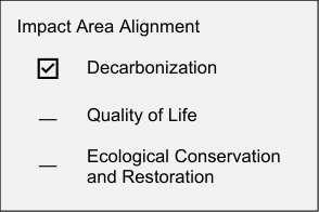
Energy and Atmosphere Prerequisite
ESTIMATED ENERGY USE AND OPERATIONAL CARBON PROJECTION
EAp1
REQUIRED
INTENT
To enable tenants and interior design teams to visualize the scale and relative impact of design decisions that will impact their project’s long-term operational carbon emissions.
REQUIREMENTS
| Achievement pathways | Points |
|---|---|
Commercial Interiors | N/A |
Provide Data on Project and Annual Energy Use | |
AND | AND |
Sign-Off on 10-Year Operational Carbon Projection | Sign-Off on 10-Year Operational Carbon Projection |
Comply with the following:
Provide Data on Project and Annual Energy Use
If the project has an energy model that includes all energy used within the project, including energy provided by base building systems, provide USGBC with the estimated annual energy use of each energy type.
If the project does not have such an energy model, provide USGBC with the following data to facilitate an annual energy calculation:
-
Project information : Occupancy type, age of building, gross area, location by zip code, and the approximate hours of occupancy on a weekly basis.
-
High-load amenity information : Include commercial kitchens, commercial laundries, data centers, etc., and the percent of gross area attributable to each.
-
Energy-related information : Lighting power density; number of LEED points pursued in reducing plug and process loads; and fuel types used for space heating, service hot water, cooking, and clothes drying as applicable.
From the data provided, USGBC will provide the project team with a rough estimate of the annual energy used of each energy type by the project.
U.S. Green Building Council LEED v5 Reference Guide for Interior Design and Construction, April 2025 Launch Edition 98
PDF Page 110
Sign-off on 10-year Operational Carbon Projection
From the modeled energy data or the energy estimate, USGBC will provide the project team with a 10-year operational carbon projection. The assumptions behind the estimate include the following:
-
No changes are made over the decade that impact energy use.
-
The initial electrical carbon coefficient is the latest subregional eGRID coefficient for projects in the U.S., or national coefficient elsewhere, or other more local coefficient that can be credibly documented.
-
The electrical carbon coefficient will decline linearly at 3.8% per year (the equivalent of declining by 95% over 25 years).
For tenant spaces, the tenant, or for owner-occupied spaces, the owner, must attest that they have reviewed the 10-year carbon projection.
REQUIREMENTS EXPLAINED
This prerequisite has two requirements which work together to help project teams understand their energy use and the impact on carbon emissions.
Provide Data on Project and Annual Energy Use
Teams must either estimate the project’s annual energy use per energy source or submit project information to inform a rough estimation of project energy usage in Arc.
When estimating energy use, include the proportionate energy use from shared base-building systems serving the project space, such as chilled water (CHW) , hot water, or shared air handling units.
Estimated annual use — energy simulation For projects completing energy modeling for EAp2: Minimum Energy Efficiency, use the summary results from the proposed energy model.
Otherwise, simplified energy modeling may be used to estimate the energy use. The simplified modeling may be from an individual model developed specifically for the project or a prototypical model representative of the project.
Other estimates of project energy consumption may include corporate estimates across the portfolio, or projections generated from the base building Energy Information System (EIS ) .
U.S. Green Building Council LEED v5 Reference Guide for Interior Design and Construction, April 2025 Launch Edition 99
PDF Page 111
Project information to inform annual energy use estimation For projects that did not create a model, provide USGBC with information to estimate project energy use in Arc [31] . Examples of information that may need uploading include:
-
General project information . Expected occupancy, age of the building, gross floor area, and location
-
High load amenity information . Any large process energy contributions to energy use, such as equipment for commercial kitchens, commercial refrigeration, laundry, data centers, laboratories, or manufacturing
-
Regulated energy information . Lighting power densities, fuel types, HVAC system types, and other factors
Sign-off on 10-year operational carbon projection USGBC will provide all LEED ID+C: Commercial Interiors projects with a business as usual (BAU) projection of the project’s operational carbon emissions over the next 25 years, based on the estimated annual energy use and the project’s current grid emissions factor. This BAU projection assumes that grid emissions factor starts with the latest national or regional coefficient, such as the subregional eGRID [32] coefficients in the US, and declines in a straight line by 95% over the next 25 years. This is meant to reflect the overall direction of grid decarbonization globally, and is not intended to be an exact prediction of individual project performance
The projection should educate owners, tenants, and designers on the carbon impacts of their design decisions over the next 10 years. Tenants, or owners in an owner-occupied space, must review the data and attest to the review.
DOCUMENTATION
| All | All | All | Design analysis during the early project design phase analyzed energy efficiency, peak load reduction, and decarbonization strategies for their impact on long- term operational carbon emissions. |
|---|---|---|---|
| All | All | All | Estimated total annual energy use of each energy source (electricity, natural gasCHW, steam, etc.) and the annual energy use for each of the following end uses: space heating, service hot water, cooking, |
31 “Home page”, Arc, Green Business Certification Inc.(GBCI), accessed March 31, 2025, https://arc.gbci.org/. 32 “Emissions and Generation Resource Integrated Database”, U.S. EPA, accessed March 31, 2025, https://www.epa.gov/egrid.
U.S. Green Building Council LEED v5 Reference Guide for Interior Design and Construction, April 2025 Launch Edition 100
PDF Page 112
| Col1 | Col2 | Col3 | cooling, refrigeration, ventilation, plug and process loads, other. |
|---|---|---|---|
Confirmation that the required entity has reviewed the carbon projection. |
REFERENCED STANDARDS
U.S. Green Building Council LEED v5 Reference Guide for Interior Design and Construction, April 2025 Launch Edition 101
PDF Page 113
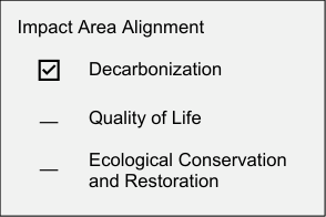
Energy and Atmosphere Prerequisite
MINIMUM ENERGY EFFICIENCY
EAp2
REQUIRED
INTENT
To promote resilience and reduce the environmental and economic harms of excessive energy use and GHG emissions by achieving a minimum level of energy efficiency.
REQUIREMENTS
| Achievement pathways | Points |
|---|---|
Commercial Interiors | N/A |
Option 1.ASHRAE 90.1-2019 | |
OR | OR |
Option 2.ASHRAE 90.1-2022 | Option 2.ASHRAE 90.1-2022 |
Projects registering before January 1, 2028, may comply with either Option 1 or Option 2.
Projects registering on or after January 1, 2028, must comply with Option 2.
Option 1. ASHRAE 90.1-2019
Comply with ANSI/ASHRAE/IES Standard 90.1-2019 .
For projects applying the Normative Appendix G, “Performance Rating Method,” compliance path, use the following:
- Future source energy metric : The future source energy metric may be used in place of the “cost”.
o Replace all references to “cost” with “future source energy.” Use an electric site
to-source energy conversion factor of 2.0 based on future projections for the U.S. A lower national average value may be used as applicable for projects outside of the U.S.
o Replace ASHRAE 90.1, Table 4.2.1.1, building performance factors (BPFs), with
the BPFs derived for the future source energy metric in Table 1.
- Alterations : For interiors project scope except initial build-out construction, apply the following ASHRAE 90.1-2022 addenda.
o Substantial alteration: Multiply the BPF by 1.05 if the alterations are defined as a
substantial alteration in ASHRAE 90.1-2022, Section G3.1.4(a).
U.S. Green Building Council LEED v5 Reference Guide for Interior Design and Construction, April 2025 Launch Edition 102
PDF Page 114
o Other alterations: Apply ASHRAE 90.1-2022, Section G3.3 (“Performance
Calculations for Other Alterations”), replacing all references to ASHRAE 90.1- 2022, Sections 5–10, prescriptive criteria with the corresponding ASHRAE 90.1- 2019, Sections 5–10 criteria.
Table 1. ASHRAE 90.1-2019 — Equivalent BPFs for a future source energy metric
| Building type | Climate zone | Col3 | Col4 | Col5 | Col6 | Col7 | Col8 | Col9 | Col10 | Col11 | Col12 | Col13 | Col14 | Col15 | Col16 | Col17 | Col18 | Col19 | Col20 |
|---|---|---|---|---|---|---|---|---|---|---|---|---|---|---|---|---|---|---|---|
| Building type | 0A | 0B | 1A | 1B | 2A | 2B | 3A | 3B | 3C | 4A | 4B | 4C | 5A | 5B | 5C | 6A | 6B | 7 | 8 |
| Multifamily | 0.74 | 0.69 | 0.73 | 0.70 | 0.73 | 0.70 | 0.71 | 0.70 | 0.63 | 0.70 | 0.71 | 0.69 | 0.68 | 0.70 | 0.70 | 0.68 | 0.68 | 0.68 | 0.74 |
| Healthcare/hospital | 0.72 | 0.72 | 0.73 | 0.73 | 0.74 | 0.71 | 0.72 | 0.74 | 0.71 | 0.72 | 0.73 | 0.71 | 0.74 | 0.73 | 0.80 | 0.73 | 0.77 | 0.78 | 0.79 |
| Hotel/motel | 0.72 | 0.71 | 0.72 | 0.71 | 0.71 | 0.70 | 0.71 | 0.73 | 0.72 | 0.71 | 0.73 | 0.73 | 0.71 | 0.73 | 0.74 | 0.70 | 0.72 | 0.70 | 0.70 |
| Office | 0.62 | 0.63 | 0.61 | 0.62 | 0.58 | 0.60 | 0.57 | 0.62 | 0.55 | 0.55 | 0.61 | 0.57 | 0.58 | 0.61 | 0.59 | 0.58 | 0.60 | 0.54 | 0.58 |
| Restaurant | 0.65 | 0.62 | 0.63 | 0.61 | 0.62 | 0.58 | 0.63 | 0.63 | 0.63 | 0.67 | 0.66 | 0.66 | 0.70 | 0.70 | 0.68 | 0.73 | 0.72 | 0.74 | 0.77 |
| Retail | 0.57 | 0.54 | 0.53 | 0.53 | 0.48 | 0.47 | 0.47 | 0.47 | 0.47 | 0.52 | 0.50 | 0.56 | 0.57 | 0.53 | 0.59 | 0.58 | 0.56 | 0.53 | 0.60 |
| School | 0.57 | 0.57 | 0.58 | 0.57 | 0.55 | 0.54 | 0.57 | 0.51 | 0.49 | 0.48 | 0.51 | 0.52 | 0.51 | 0.53 | 0.51 | 0.53 | 0.50 | 0.51 | 0.58 |
| Warehouse | 0.28 | 0.30 | 0.24 | 0.27 | 0.23 | 0.24 | 0.27 | 0.23 | 0.20 | 0.33 | 0.26 | 0.28 | 0.40 | 0.32 | 0.29 | 0.44 | 0.38 | 0.40 | 0.44 |
| All others | 0.65 | 0.62 | 0.64 | 0.62 | 0.57 | 0.54 | 0.57 | 0.56 | 0.58 | 0.59 | 0.57 | 0.60 | 0.60 | 0.59 | 0.65 | 0.62 | 0.62 | 0.61 | 0.64 |
OR
Option 2. ASHRAE 90.l-2022
Comply with ANSI/ASHRAE/IES Standard 90.1-2022 . Use any applicable compliance path in ASHRAE 90.1, Section 4.2, or an approved equivalent standard for elements within the project scope.
For projects applying the Normative Appendix G, “Performance Rating Method” compliance path, one of the following metrics may be used in place of “cost”:
- Future source energy
o Replace all references to “cost” with “future source energy.” Use an electric site
to-source energy conversion factor of 2.0 based on future projections for the U.S. A lower national average value may be used as applicable for projects outside of the U.S.
o Replace ASHRAE 90.1, Table 4.2.1.1, BPFs with the BPFs derived for the future
source energy metric in Table 2.
- Site energy or source energy documented using ASHRAE 90.1-2022, Informative Appendix I.
U.S. Green Building Council LEED v5 Reference Guide for Interior Design and Construction, April 2025 Launch Edition 103
PDF Page 115
Table 2. ASHRAE 90.1-2022 — Equivalent BPFs for a future source energy metric
| Building type | Climate zone | Col3 | Col4 | Col5 | Col6 | Col7 | Col8 | Col9 | Col10 | Col11 | Col12 | Col13 | Col14 | Col15 | Col16 | Col17 | Col18 | Col19 | Col20 |
|---|---|---|---|---|---|---|---|---|---|---|---|---|---|---|---|---|---|---|---|
| Building type | 0A | 0B | 1A | 1B | 2A | 2B | 3A | 3B | 3C | 4A | 4B | 4C | 5A | 5B | 5C | 6A | 6B | 7 | 8 |
| Multifamily | 0.64 | 0.59 | 0.62 | 0.60 | 0.61 | 0.59 | 0.61 | 0.60 | 0.49 | 0.57 | 0.59 | 0.56 | 0.55 | 0.57 | 0.57 | 0.55 | 0.55 | 0.55 | 0.60 |
| Healthcare/hospital | 0.64 | 0.64 | 0.66 | 0.65 | 0.66 | 0.63 | 0.64 | 0.65 | 0.63 | 0.64 | 0.65 | 0.62 | 0.64 | 0.62 | 0.69 | 0.63 | 0.68 | 0.69 | 0.70 |
| Hotel/motel | 0.65 | 0.63 | 0.64 | 0.63 | 0.62 | 0.61 | 0.62 | 0.63 | 0.62 | 0.59 | 0.60 | 0.60 | 0.57 | 0.58 | 0.59 | 0.56 | 0.58 | 0.56 | 0.56 |
| Office | 0.54 | 0.54 | 0.53 | 0.54 | 0.49 | 0.52 | 0.49 | 0.52 | 0.45 | 0.46 | 0.52 | 0.47 | 0.48 | 0.51 | 0.48 | 0.48 | 0.50 | 0.45 | 0.49 |
| Restaurant | 0.61 | 0.58 | 0.58 | 0.57 | 0.57 | 0.54 | 0.58 | 0.59 | 0.57 | 0.62 | 0.61 | 0.61 | 0.65 | 0.64 | 0.63 | 0.67 | 0.66 | 0.69 | 0.72 |
| Retail | 0.47 | 0.45 | 0.44 | 0.44 | 0.40 | 0.39 | 0.37 | 0.39 | 0.36 | 0.40 | 0.41 | 0.42 | 0.45 | 0.43 | 0.46 | 0.44 | 0.43 | 0.42 | 0.46 |
| School | 0.52 | 0.53 | 0.53 | 0.53 | 0.51 | 0.51 | 0.53 | 0.48 | 0.46 | 0.43 | 0.48 | 0.47 | 0.45 | 0.49 | 0.46 | 0.46 | 0.44 | 0.44 | 0.48 |
| Warehouse | 0.25 | 0.25 | 0.21 | 0.24 | 0.20 | 0.21 | 0.24 | 0.20 | 0.17 | 0.30 | 0.22 | 0.25 | 0.36 | 0.28 | 0.25 | 0.40 | 0.34 | 0.36 | 0.40 |
| All others | 0.58 | 0.56 | 0.56 | 0.56 | 0.50 | 0.47 | 0.49 | 0.48 | 0.48 | 0.49 | 0.49 | 0.50 | 0.51 | 0.50 | 0.55 | 0.52 | 0.52 | 0.52 | 0.55 |
REQUIREMENTS EXPLAINED
Widely referenced in building codes and regulations, the ASHRAE 90.1 standard determines the minimum energy efficiency required for prerequisite compliance.
Required ASHRAE Standard 90.1 Version
The required efficiency increases for project registrations beginning in 2028, stepping up from ASHRAE 90.1-2019 standard to the more stringent ASHRAE 90.1-2022 standard. Compliance with the requirements of ASHRAE 90.1-2022 achieves a net average site energy savings of 14% compared to ASHRAE 90.1-2019, when including savings for prescriptively required renewable energy.
OPTION 1. ASHRAE 90.1-2019
Only projects registered before January 1, 2028, can use ASHRAE 90.1-2019 .
OPTION 2. ASHRAE 90.1-2022
Projects registered after January 1, 2028, must use ASHRAE 90.1-2022 .
Projects registered before January 1, 2028, can elect to use the 2022 version of the standard to earn points under EAc2: Enhanced Energy Efficiency .
For a summary of key changes to the ASHRAE 90.1 standard between the 2019 and 2022 publications, refer to ASHRAE 90.1-2022 Foreword and ASHRAE 90.1-2022, Informative Appendix M, Addenda Description.
U.S. Green Building Council LEED v5 Reference Guide for Interior Design and Construction, April 2025 Launch Edition 104
PDF Page 116
Summary of ASHRAE 90.1, Section 4.2.1 compliance paths Projects must choose from one of the following compliance paths from ASHRAE 90.1, Section 4.2.1.3. Alterations of Existing Buildings:
- Prescriptive method
o ASHRAE 90.1-2019, Sections 5–10 (for projects applying Option 1)
o ASHRAE 90.1-2022, Sections 5–11 (for projects applying Option 2)
-
Energy cost budget method (ECB)
-
Appendix G performance rating method (PRM)
The path commonly referred to as the prescriptive method requires individual compliance with each referenced 90.1 section for the elements within the project scope (building envelope, HVAC, SWH, electrical power, lighting, other equipment, and in 90.1-2022, additional efficiency requirements). It is the most appropriate path for projects with limited scope.
The ECB method and Appendix G PRM offer greater flexibility to trade-off performance between different systems. These methods rely on energy modeling to demonstrate that the proposed project performs at least as well as a project meeting the prescriptive requirements.
Project teams must apply either the prescriptive method or the Appendix G PRM to pursue additional credit for regulated energy efficiency in EAc2: Enhanced Energy Efficiency .
Initial build-out, substantial alterations, and other alterations ASHRAE 90.1-2022 requires initial build-out projects and substantial alterations to meet a higher bar for energy efficiency than other interiors projects. Similar increased efficiency criteria apply to initial buildouts and substantial alterations documented using ASHRAE 90.1-2019, Appendix G.
-
Initial buildout . This refers to work to finish a space within a building for initial occupancy.
-
Substantial alterations . This refers to major replacement of systems or components in existing buildings for two out of three major building systems (HVAC, lighting, or building envelope). Refer to ASHRAE 90.1-2022, Section 11.1.4.1 Substantial Alterations to Existing Buildings for a full definition.
-
Other alterations . This refers to interior fit-outs of existing buildings that are not substantial alterations.
ASHRAE 90.1-2022, Section 11 Additional Efficiency Requirements apply to initial buildouts and substantial alterations, but not to other alterations. These additional savings are also accounted for in determination of ASHRAE 90.1-2022, ECB method requirements.
U.S. Green Building Council LEED v5 Reference Guide for Interior Design and Construction, April 2025 Launch Edition 105
PDF Page 117
ASHRAE 90.1-2022, Appendix G PRM differentiates the methodology used for new buildings, substantial alterations, and other alterations. This provides a fairer evaluation of project performance than earlier versions of ASHRAE 90.1, Appendix G PRM, where compliance was unachievable for projects with limited scope.
For projects documented using ASHRAE 90.1-2019, Appendix G PRM, the LEED rating system pairs this improved methodology from the 90.1-2022, Appendix G PRM with less stringent BPFs than from the 90.1-2019, Appendix G PRM.
ASHRAE 90.1 mandatory provisions All projects must meet mandatory provisions applicable to the project scope from the referenced version of ASHRAE 90.1, found in Sections: 5.4 (Building Envelope), 6.4 (HVAC), 7.4 (SWH), 8.4 (Power), 9.4 (Lighting), and 10.4 (Other Equipment).
Early in the design process, the project architect, engineer, and lighting designer should review these provisions and ensure they are integrated into the project design.
EXCEPTIONS TO MANDATORY PROVISIONS Project-specific exceptions or Project Priority Library alternatives to the mandatory provisions may apply to:
o Projects outside the U.S. where variations in equipment rating methodologies or
limited availability of the required equipment or controls precludes compliance.
o Provisions exempted by the local AHJ in areas regulated by codes of similar
stringency to the referenced version of ASHRAE 90.1 .
o Provisions that can be directly accounted for in ASHRAE 90.1, Appendix G PRM
energy simulation.
Further description of ASHRAE 90.1 Section 4.2.1 compliance paths
ASHRAE 90.1 4.2.1 compliance path: prescriptive method For the prescriptive method, projects must meet all requirements applicable to the project scope from each referenced ASHRAE 90.1 section. No trade-offs are permitted between the provisions of each section.
-
Section 5 . Building Envelope
-
Section 6 . HVAC
-
Section 7 . SWH
-
Section 8 . Power
-
Section 9 . Lighting
U.S. Green Building Council LEED v5 Reference Guide for Interior Design and Construction, April 2025 Launch Edition 106
PDF Page 118
- Section 10 . Other Equipment
For ASHRAE 90.1-2022, Section 11 Additional Efficiency Requirements (applicable to initial buildouts and substantial alterations), the intent behind this method is to provide a straightforward, easy-to-follow path to compliance. This method is particularly useful for smaller projects or those with less complex designs, where flexibility is less of a concern.
The prescriptive method is primarily a checklist approach. It specifies minimum requirements for various building components, such as insulation levels, window performance, lighting power densities, HVAC system efficiencies, and system controls. [33]
Some sections provide an option for limited trade-offs within the section. For example, spaces matching the ASHRAE 90.1 definition of computer room, such as data centers or server rooms, may comply with ASHRAE 90.4 (i.e., 90.1, Section 6.6.1 Computer Room System Path and 90.1 Section 8.6.1 Computer Room Systems). The other trade-off methods do not typically apply to Interiors scope of work (i.e., 90.1, Section 5.6 Building Envelope Trade-off Compliance Path and 90.1-2022, Section 6.6.2 Mechanical System Performance Path).
Additional considerations EAc2: Enhanced Energy Efficiency, Option 1. Prescriptive Path
ASHRAE 90.1-2019 . Projects that comply with Option 1 of the prerequisite using the ASHRAE 90.1-2019 prescriptive method may earn points for additional improvements to regulated systems. (Refer to Path 2. Regulated Loads).
ASHRAE 90.1-2022 . Projects that comply with Option 2 of the prerequisite using the ASHRAE 90.1-2022 prescriptive method are awarded three points under Path 1. ASHRAE 90.1-2022 compliance for project scope.
Further points are available for additional improvements to regulated systems (Refer to Path 2. Regulated Loads).
Prescriptive method: Option 2. ASHRAE 90.1-2022, Section 11 Additional Efficiency Requirements ASHRAE 90.1-2022, Section 11 Additional Efficiency Requirements is applicable to initial buildout construction and substantial alterations.
33 “Performance-Based Compliance, Building Energy Codes Program”, U.S. Department of Energy, accessed March 31, 2025, https://www.energycodes.gov/performance_based_compliance.
U.S. Green Building Council LEED v5 Reference Guide for Interior Design and Construction, April 2025 Launch Edition 107
PDF Page 119
For these project types, designers must select from a list of additional efficiency measures in Section 11 to earn the minimum number of “Energy Credits” required for the project’s building type and climate zone per Table 11.5.1-1. This affords a greater degree of flexibility for the project team to select the additional measures most feasible and appropriate for their project application.
Each of the efficiency measures referenced in Section 11 are awarded a specific number of base “Energy Credits” per building type and climate, equating to approximately 0.1% savings per credit (see ASHRAE 90.1-22, Tables 11.5.3-1–11.5.3-9). Section 11.5.2 outlines opportunities for further adjustments to augment these base credits for certain efficiency measures.
For example, an office project in climate zone 4A earns 8 base credits for achieving a 5% reduction in lighting power (L06), but this increases to 16 credits for a 10% reduction per the adjustment described in the detailed summary of this measure.
Combined credits for renewable and load management measures are limited to 60% of the total required energy credits per ASHRAE 90.1-2022, Section 11.5.2.
ASHRAE 90.1-2022, Addendum J provides an option for projects to use the Total System Performance Ratio (TSPR) to demonstrate overall improvement in HVAC performance rather than applying individual system efficiency measures.
ENERGY CREDIT ADJUSTMENTS (ASHRAE 90.1-2022 11.5.1)
o Mixed use projects . For projects with multiple building types, minimum required
credits and credits achieved are weighted by the gross floor area of each building type.
o Minimum required “Energy Credits” are adjusted lower than the default thresholds in
Table 11.5.1.1-1 for initial build-out construction and substantial alterations.
-
Initial buildout projects must achieve between 25% and 50% of the referenced thresholds dependent on the project scope.
-
Substantial alterations must achieve 50% of the referenced thresholds.
o Projects without roof availability for photovoltaic (PV) or meeting Section 10.5.1
exceptions may use the referenced equation to adjust required credits below the default threshold per Section 11.5.1(e).
- Unconditioned spaces, semi-heated spaces, and parking garages must
achieve 50% of the credits referenced for “Other” building types in Table 11.5.1.1-1.
ASHRAE 90.1 4.2.1 compliance path: ECB method This approach compares the annual energy cost of the proposed design to that of a budget building. The budget building is essentially a clone of the proposed design but adjusted to just
U.S. Green Building Council LEED v5 Reference Guide for Interior Design and Construction, April 2025 Launch Edition 108
PDF Page 120
meet the prescriptive requirements. ASHRAE 90.1-2019 compliance is achieved if the proposed design’s energy cost is no greater than the budget. For ASHRAE 90.1-2022, an additional improvement below the ECB must be met based on an adjustment referencing the prescriptively required “energy credits” from Section 11. Refer to the Building Envelope Backstop section for further guidance addressing limitations on envelope trade-offs when applying the ECB Method.
The ECB Method may not be used to demonstrate improvement in regulated energy savings for EAc2: Enhanced Energy Efficiency.
ASHRAE 90.1 4.2.1 compliance path: Appendix G PRM stable baseline For initial buildouts and substantial alterations, this path holistically evaluates building performance including base building systems and systems modified in the project scope. Projects locating in underperforming buildings will have difficulty showing compliance using this path.
For initial buildouts and substantial alterations, ASHRAE 90.1, Appendix G PRM utilizes a “stable baseline” methodology that supports comparison of building performance across versions of ASHRAE 90.1 using a variety of performance metrics. Using the PRM, an energy modeler can develop a single set of ASHRAE 90.1, Appendix G Baseline Building Design and Proposed Building Design models to document compliance with this prerequisite, with EAc2: Enhanced Energy Efficiency, and with any code requirements linked to ASHRAE 90.1-2016 or later, or IECC-2018 or later.
The stable baseline methodology in the PRM requires a Performance Index (PI) less than or equal to the Performance Index Target (PIT ), with further adjustments and limitations addressing on-site renewable energy. The scale for the PI ranges from one to zero (1–0), where one (1) represents a baseline building that minimally complies with 90.1-2004 ASHRAE requirements and zero (0) represents a net zero building.
The PIT is calculated using the results of the baseline building model completed in accordance with the PRM protocol and the BPF for the project type and climate zone. The BPFs are provided in ASHRAE 90.1, Table 4.2.1.1 for the metric of energy cost.
Substantial alterations have slightly less stringent PITs than new buildings, determined by multiplying published BPFs by a factor of 1.05 (See ASHRAE 90.1-2019, Addendum cr or ASHRAE 90.1-2022 4.2.1.3 ).
Appendix G PRM, performance calculations for other alterations (90.1-2022 G3.3) For other alterations (alterations that are not initial buildouts or substantial alterations), the stable baseline methodology does not apply. The methodology is similar to ASHRAE 90.1-2010,
U.S. Green Building Council LEED v5 Reference Guide for Interior Design and Construction, April 2025 Launch Edition 109
PDF Page 121
Appendix G, which directly compares the performance of the proposed design to that of a baseline building matching the prescriptive requirements. A BPF of 1.0 is used for all projects. Systems and equipment excluded from the scope of retrofit are modeled identically in the baseline and proposed models.
Appendix G PRM, alternative metrics in lieu of energy cost Although the ASHRAE 90.1, Appendix G PRM references a cost metric, the energy modeler may instead demonstrate EAp2: Minimum Energy compliance for the PRM using the future source energy metric referenced in EAc2: Enhanced Energy Efficiency, or a site energy metric, or a current source energy metric. Substitute all PRM references to “cost” with the new metric. BPFs used to assess compliance must be specific to the metric and the referenced version of ASHRAE Standard 90.1 .
EAc2: Enhanced Energy Efficiency only uses the future source energy metric and does not allow the use of the energy cost, site energy, or source energy metrics (See EAc2: Enhanced Energy Efficiency, Option 2 ).
Energy modelers can limit documentation level of effort by calculating both prerequisite and credit compliance using the future source energy metric.
For initial buildout and substantial alterations, adjust the BPFs to align with the selected metric. For other alterations, the BPF is always 1.
OPTION 1. ASHRAE 90.1-2019, APPENDIX G PRM. ALTERNATIVE METRICS
-
Future source energy . Calculate the PIT for both the prerequisite and EAc2: Enhanced Energy Efficiency with BPFs from the prerequisite Table 1. 90.1-2019 equivalent BPFs for a future source energy metric.
-
Site energy or source energy metric . (prerequisite only) Apply ASHRAE 90.1-2019, Addendum ch . For a source energy metric, match those listed in Addendum ch Table X4-1 and follow Addendum ch Section X5 Methodology for BPF Adjustment to Account for Localized Conversion Factors.
OPTION 2. ASHRAE 90.1-2022, APPENDIX G PRM. ALTERNATIVE METRICS
Future source energy metric - Calculate the PIT for the prerequisite with BPFs from the prerequisite. See Table 2, ASHRAE 90.1-2022 — Equivalent BPFs for a future source energy metric.
Calculate the less stringent PIT for EAc2: Enhanced Energy Efficiency using Table 6. 90.1-2019 equivalent BPFs for a future source energy metric.
U.S. Green Building Council LEED v5 Reference Guide for Interior Design and Construction, April 2025 Launch Edition 110
PDF Page 122
-
Site energy or source energy metric . (prerequisite only). Apply ASHRAE 90.1-2022, Informative Appendix I. For the source energy metric, use the 90.1-2022 Appendix I5. Methodology for BPF Adjustment to Account for Localized Conversion Factors if the project source energy conversions do not match those listed in Addendum Table I4-1.
- Appendix G PRM, treatment of on-site renewable energy . Per ASHRAE 90.1, the renewable energy contribution toward meeting PRM requirements is limited to 5% of baseline building performance (BBP).
This varies from EAc2: Enhanced Energy Efficiency, Option 2, which either includes or excludes the entire renewable contribution from determination of credit compliance.
Appendix G PRM, exceptions to mandatory measures For mandatory measures where the savings associated with the measure can be documented in the energy simulation, the modeler may account for the absence of the mandatory measure in the energy simulation in lieu of compliance with the mandatory provisions. Model the BBP per Appendix G requirements and the proposed building performance (PBP) as designed for measures that are not required to be included in the BBP, such as daylighting controls. For measures where Appendix G requires the PBP to match the BBP, model the measure as present in the baseline BBP and absent in the proposed PBP.
Appendix G PRM, modeling shared HVAC and SWH systems For projects with shared base building HVAC or service water heating (SWH) systems, teams may model only the project space instead of following Appendix G PRM, Table G3.2, Additions and Alterations requirements to model the full area served by the shared HVAC systems.
If modeling only the project space, either treat shared CHW and shared hot water as District Energy Systems (DES) or allocate the base building HVAC and SWH to the project space.
Baseline design for projects with shared systems The Baseline HVAC system type must be determined based on the base building parameters unless Section G3.1.1 or additional or adjusted baseline HVAC system types applies to the interiors project space.
Base building parameters include building type, number of floors, conditioned floor area, and building peak cooling load.
U.S. Green Building Council LEED v5 Reference Guide for Interior Design and Construction, April 2025 Launch Edition 111
PDF Page 123
Proposed design: Allocation of shared systems For shared systems serving similar occupancies, allocate based on area served by the system. Multiply each shared system design parameter by the ratio of “total project floor area served” to “total gross floor area served.”
For shared systems serving dissimilar occupancies, allocate based on the proportion of total design capacity serving the project.
Equivalence to ASHRAE 90.1 Refer to the Project Priorities Library for regional paths addressing equivalence to ASHRAE 90.1.
For projects in the U.S., state or local codes are considered “equivalent” to ASHRAE 90.1-2019 or ASHRAE 90.1-2022 when the U.S. Department of Energy Building Energy Codes Program status of state energy code adoption indicates a commercial code efficiency category matching the referenced version of ASHRAE 90.1 or later for the project location in effect at the time of project permit application.
The 2021 International Energy Conservation Code ( IECC 2021 ) is recognized as equivalent to ASHRAE 90.1-2019 .
The 2024 International Energy Conservation Code ( IECC 2024 ) is recognized as equivalent to ASHRAE 90.1-2022 .
For both versions of IECC:
-
IECC Section C407 Total Building Performance may be used to document prerequisite compliance only.
-
IECC Prescriptive compliance (C402–C406) may be used in lieu of the ASHRAE 90.1- 2019 prescriptive method.
District energy systems (DES) ASHRAE 90.1 refers to DES as “purchased CHW” or “purchased heat” even when this energy is part of a campus distribution plant and not directly purchased from a utility or municipality.
Because DES systems are outside of the project scope of work, DES efficiency cannot contribute toward achievement of prerequisite compliance. Central hot water and CHW systems serving the Interiors project space may be treated the same as purchased heat and/or purchased CHW using this guidance.
U.S. Green Building Council LEED v5 Reference Guide for Interior Design and Construction, April 2025 Launch Edition 112
PDF Page 124
For projects that use the ECB method, model purchased heat and/or purchased CHW as independent energy sources using the same utility rates per unit of energy for the ECB and design energy cost models.
For projects that use the PRM, use one of the following modeling methods to document the DES:
METHOD A. ASHRAE 90.1-2022 ADDENDUM A. (Removes inherent DES Penalty)
The project may apply ASHRAE 90.1-2022, Addendum A to either the ASHRAE 90.1- 2019 or ASHRAE 90.1-2022, Appendix G criteria as applicable to avoid the inherent penalty in the Appendix G PRM Performance Index Targets when modeling “purchased heat” and “purchased CHW.”
Model HVAC systems for the baseline building design per ASHRAE 90.1-2022, Addendum A criteria as if all heating and cooling generation equipment is on-site.
Model the proposed design with natural gas forced draft boilers in place of district heating and water-cooled chillers in place of district cooling, matching the type and number specified in Addendum A. For projects using ASHRAE 90.1-2019, replace all ASHRAE 90.1-2022, Addendum A references to Section 6 prescriptive criteria for the proposed building design with ASHRAE 90.1-2019, Section 6. Additional Considerations
Additional considerations: Linked credits
EAc2: Enhanced Energy Efficiency . Use Method A for prerequisite compliance if crediting DES efficiency toward the project performance in EAc2: Enhanced Energy Efficiency .
EAc3: Renewable Energy . In the energy simulation, use submetering to distinguish fuel used on-site from the modeled fuel use for the district hot water plant. This information is necessary to inform the EAc3: Renewable Energy, Renewable Energy Attributes, Project Energy Source criteria .
METHOD B. DIRECTLY MODEL PURCHASED HEAT AND/OR PURCHASED CHW. Apply the PRM requirements to model purchased heat and/or purchased CHW as independent energy sources in the baseline and proposed design, with the same utility rates or source energy conversion factors for the baseline and proposed design. Use published utility rates or source energy conversion factors when available. Otherwise, if purchased energy rates or source energy conversion factors are not published for the
U.S. Green Building Council LEED v5 Reference Guide for Interior Design and Construction, April 2025 Launch Edition 113
PDF Page 125
district energy sources serving the project, derive these purchased energy rates and/or conversion factors as follows:
o Purchased chilled water (CHW) . Multiply the utility rate or source energy
conversion factor for electricity by a factor of 0.325 to estimate the CHW utility rate or source energy conversion factor.
o Purchased heat from district hot water (HHW) . Multiply the utility rate or
source energy conversion factor by a factor of 1.5 for the predominant fossil fuel source used to generate the district hot water or natural gas if unknown.
o Purchased heat from district steam . Multiply the utility rate or source energy
conversion factor by a factor of 1.7 for the predominant fossil fuel source used to generate the district hot water or natural gas if unknown.
Summary of EA credit linkages to EAp2: Minimum Energy Efficiency
| Col1 | Option 1 ASHRAE 90.1-2019 | Option 2. ASHRAE 90.1-2022 |
|---|---|---|
| Applicability | Limited to projects registered prior to January 1, 2028. | Available to all projects. Required for projects registered on or after January 1, 2028. |
| Linked Credits: | ||
EAc2: Enhanced Energy Efficiency | EAc2: Enhanced Energy Efficiency | EAc2: Enhanced Energy Efficiency |
Prescriptive Method (Option 1, Paths 1 and 2 of the credit) | Required as precondition to document points for additional efficiency. (See Path 2, Case 1) | 3 points automatically awarded for prerequisite compliance using Prescriptive Method. (Path 1) Further points for additional efficiency using either Case 1. Systems Optimization or Case 2. Additional efficiency requirements beyond_ASHRAE_ 90.1-2022. |
| Appendix G PRM (Option 2 of the credit) NOTE**:** Treatment of on-site renewable energy varies from prerequisite. | Incremental performance improvement documented using the future source energy metric earns points. | Points awarded for improvement beyond a 90.1-2019 equivalent-baseline using the future source energy metric. Performance target for prerequisite and credit determined separately using simple calculation adjusting referenced BPF. |
U.S. Green Building Council LEED v5 Reference Guide for Interior Design and Construction, April 2025 Launch Edition 114
PDF Page 126
DOCUMENTATION
| Project types | Options | Paths | Documentation |
|---|---|---|---|
| All | All | All | Document compliance with mandatory measures from ASHRAE Standard 90.1 |
| All | All | Prescriptive method | ASHRAE 90.1 compliance forms or Comcheck compliance report confirming a system-by-system approach. |
| All | All | Energy simulation (ASHRAE 90.1, Appendix G PRM or ECB Method) | ASHRAE 90.1 compliance forms. |
| All | All | Energy simulation (ASHRAE 90.1, Appendix G PRM or ECB Method) | Input-output reports from modeling software. |
| All | All | Energy simulation (ASHRAE 90.1, Appendix G PRM or ECB Method) | Energy consumption and demand for each building end-use and energy source. |
| All | All | Energy simulation (ASHRAE 90.1, Appendix G PRM or ECB Method) | Exceptional calculation and supporting documentation for referenced metrics (if applicable) |
| All | All | Energy simulation (ASHRAE 90.1, Appendix G PRM or ECB Method) | USGBC Minimum Energy Efficiency calculator or ASHRAE Standard 90.1 Performance Based Compliance Form |
| All | DES | All | Documentation on DES including energy source serving the project. |
REFERENCED STANDARDS
-
ASHRAE 90.1-2019 (store.accuristech.com/ashrae/standards/ashrae-90-1-2019-i- p?product_id=2088527)
-
ASHRAE 90.1-2022 (store.accuristech.com/ashrae/standards/ashrae-90-1-2022-i- p?product_id=2522082)
U.S. Green Building Council LEED v5 Reference Guide for Interior Design and Construction, April 2025 Launch Edition 115
PDF Page 127
Energy and Atmosphere Prerequisite
FUNDAMENTAL COMMISSIONING
EAp3
REQUIRED
INTENT
To improve energy performance and limit GHG emissions by verifying that systems are operating per the OPR.
REQUIREMENTS
| Achievement pathways | Points |
|---|---|
Commercial Interiors | N/A |
Comply With Commissioning Requirements |
Comply with ANSI/ASHRAE/IES Standard 90.1 ’s commissioning requirements for building systems, controls, and the building envelope, as applicable to the project scope, with the following additional provisions:
-
All projects shall provide commissioning that addresses the project scope of work, including any tenant interfaces or interconnections with base building systems. Section 4.2.5.2 exceptions shall not apply.
-
The referenced version of Standard 90.1 with errata shall be:
o 2019 or later for projects registered before January 1, 2028.
o 2022 or later for projects registered on or after January 1, 2028.
-
By the end of the design development phase, the owner shall designate a commissioning provider (CxP) with experience completing commissioning on at least two projects of equal or larger scope and complexity. For alterations meeting the criteria in Exception 4.2.5.2, the CxP may be directly associated with design or installation of the building systems or controls being commissioned.
-
In addition to the requirements of the applicable version of ASHRAE 90.1, the CxP shall:
o In predesign, or as early as possible, assist in the development of the OPR,
reviewing and updating the OPR through design and construction. OPR must address project scope of work for HVAC, SWH, power, lighting, other equipment including on-site renewable energy, and envelope.
o During design, review the BOD for compliance with the OPR, and attend at least
one meeting to discuss review comments and commissioning.
o During construction, review submittals and substitutions for design deviations
that impact the OPR, attend at least one milestone meeting, and perform a
U.S. Green Building Council LEED v5 Reference Guide for Interior Design and Construction, April 2025 Launch Edition 116
PDF Page 128
sample review (minimum 10%) of completed contractor documentation for QA/QC.
REQUIREMENTS EXPLAINED
For the elements within the project scope of work, the prerequisite stipulates that projects perform commissioning for building systems, controls, and the building envelope in compliance with the minimum requirements of ASHRAE Standard 90.1, and additional provisions of the LEED ID+C rating system .
Automatic achievement of prerequisite through EAc4: Enhanced Commissioning, Option 1 Projects that achieve EAc4: Enhanced Commissioning, Option 1 automatically comply with the prerequisite requirements, since the credit requirements encompass all commissioning requirements from the ASHRAE 90.1 standard referenced in EAp3: Fundamental Commissioning .
Therefore, when planning commissioning scope, review the EAc4: Enhanced Commissioning, Option 1 requirements, paying special attention to the required timing for CxP engagement during predesign or very early in the commissioning process to accomplish the broader commissioning scope of work required for credit compliance.
Tables 1 below provide a comparison of required tasks for EAp3: Fundamental Commissioning compared to EAc4: Enhanced Commissioning, Option 1 .
Required ASHRAE Standard 90.1 version Projects registered before January 1, 2028, can reference ASHRAE Standard 90.1-2019, or any later version. Projects registered on or after January 1, 2028, must use ASHRAE Standard 90.1- 2022 or later.
The commissioning requirements are similar for the 2019 and 2022 versions of ASHRAE 90.1 .
Additional considerations Using a single version of ASHRAE Standard 90.1 for EAp2: Minimum Energy Efficiency, EAp3: Fundamental Commissioning, and EAp4: Energy Metering and reporting streamlines documentation efforts.
U.S. Green Building Council LEED v5 Reference Guide for Interior Design and Construction, April 2025 Launch Edition 117
PDF Page 129
Approved equivalent standards Projects may use IECC 2021 [34] in lieu of ASHRAE Standard 90.1-2019 and IECC 2024 [35] in lieu of ASHRAE Standard 90.1-2022 . Projects that use IECC instead of ASHRAE must still comply with all additional LEED ID+C rating system requirements.
Selecting the CxP As buildings and systems become more complex and as the systems required for Cx expand beyond traditional mechanical equipment, many CxPs will consist of a team instead of an individual person. Therefore, either an entity or an individual can act as the CxP. For projects that use a CxP entity, designating a single person as the Cx project lead or manager ensures consistency in documentation and quality control of the process.
Minimum qualifications The CxP must have direct commissioning experience from the design phase through the construction phase for at least two projects with equal or larger scope and complexity. The previous experience should address projects of similar types and size range, similar types and capacities of HVAC and SWH equipment, and controls with similar complexity.
Experience documented for a CxP entity must reflect the team performing the commissioning work for the project.
Eligible entities Per ASHRAE Standard 90.1-2019, Section 4.2.5.2 , the CxP must be completely independent from the design or construction team. Consider the following when selecting a CxP:
-
The CxP can be a third-party entity not currently contracted for any design or construction aspects of the project.
-
The CxP can be employed by the owner, provided that the entity meets the CxP minimum qualifications.
-
If the CxP is employed by any company that has direct influence on the design and construction, the commissioning plan must clearly address any potential conflicts of interest and demonstrate that the CxP acts and operates solely on the behalf of the owner, reports directly to the owner, and works entirely independently from the design and construction team.
-
The CxP can be employed by the company performing the design or construction of the project; however, they must be a completely independent member of the design team,
34 “International Energy Conservation Code”, International Code Council (ICC), accessed March 31, 2025, https://codes.iccsafe.org/codes/i-codes. 35 International Energy Conservation Code”, ICC.
U.S. Green Building Council LEED v5 Reference Guide for Interior Design and Construction, April 2025 Launch Edition 118
PDF Page 130
and not directly associated with any aspect of the design and/or installation of the project systems.
CxP eligible entities for projects with limited scope For prerequisite compliance, the CxP may be directly associated with design or installation of the commissioned systems if one of the ASHRAE 90.1, Section 4.2.5.2 exceptions apply:
-
There are fewer than 10,000 square feet (930 square meters) of conditioned space with combined heating, cooling, and SWH equipment capacity totaling fewer than 960,000 Btu/h (280 kW).
-
The project complies with ASHRAE 90.1, Section 6.3 Simplified Building Compliance Path for Systems.
-
There are nonrefrigerated warehouses.
Verification and testing (V&T) providers ASHRAE Standard 90.1 also requires that the CxP include V&T providers. A V&T provider is an entity that completes the activities needed to implement the project functional performance testing (FPT) activities or verify that elements of the project meet stated requirements. In many cases, the entity acting as the CxP fulfills this requirement. Confirm that an individual, qualified in verification and FPT execution is part of the commissioning team.
CxP requirements for building envelope commissioning If the project scope includes the building envelope, the CxP must include qualified individuals who can perform the envelope design review and air barrier inspection or a V&T provider who can perform air leakage testing.
Timing for CxP engagement Identify a CxP no later than the end of the design development phase. The CxP has the primary responsibility of leading the design and construction team through all aspects of the commissioning.
Additional considerations A single entity can perform all system commissioning efforts, provided that the entity meets the minimum requirements outlined.
For projects that use different qualified individuals to perform various Cx tasks, ensure sufficient collaboration within the team to provide continuity from design through operations. For example, an entity may have different
U.S. Green Building Council LEED v5 Reference Guide for Interior Design and Construction, April 2025 Launch Edition 119
PDF Page 131
CxP team members review the design documents than the team witnessing testing.
Scope of fundamental commissioning The prerequisite stipulates that projects conform with ASHRAE Standard 90.1 requirements for all referenced systems and additional provisions as outlined in the LEED ID+C: Commercial Interiors rating system.
Systems requiring commissioning. At a minimum, commissioned systems must include all energy-using systems within the project scope of work that are referenced in ASHRAE 90.1, Sections 5–10, including the building envelope, HVAC, SWH, power, lighting, on-site renewable energy, energy monitoring systems, refrigeration equipment, energy storage systems, load management systems, and other energyusing systems.
Owner’s Project Requirements (OPR) The OPR documents the functional requirements of the building. It also details the expectations of the project’s use and operation. The OPR includes objectives for the project which verify that all stated goals become integral with the project design, construction, and operation.
The owner or a design professional can develop the OPR. However, the owner must provide input during the development. This ensures that the OPR captures critical elements, like sustainability goals and targets for the project. If a CxP’s engagement begins prior to the OPR development, the CxP may provide input on the initial development efforts. The OPR is a living document, which requires ongoing updates throughout the design phases.
Additional considerations The owner plays a critical role in developing and updating the OPR. The OPR establishes a clear vision for the project, identifying expected outcomes and goals for sustainable project development. As the project progresses, decisions made for the project should align with the OPR. It is important that the owner remain a key stakeholder, and ultimate approver of the final version of the document.
Basis of design (BOD) The project’s design professionals typically create the BOD. The BOD explains how the design and construction team will execute the OPR. Processes and assumptions made early in the design phases to achieve the OPR’s intent should be included in the BOD, along with relevant project information. A BOD addresses performance criteria, general project characteristics (envelope, HVAC, water), and governing codes and standards, at minimum.
U.S. Green Building Council LEED v5 Reference Guide for Interior Design and Construction, April 2025 Launch Edition 120
PDF Page 132
The BOD is a living document, which requires updates throughout the design and construction phases.
Design reviews and design phase meetings Design reviews by the CxP are critical elements of the commissioning process. Reviews support the energy efficiency goals of ASHRAE Standard 90.1 by verifying that the design meets the requirements of the standard. Early reviews allow teams to correct areas of the design that do not meet the requirements before construction begins. This avoids costly change orders during construction.
Along with design reviews, the CxP must review the OPR and BOD. The CxP must also confirm that the construction documents include required commissioning information.
The design reviews should confirm that the design meets relevant energy efficiency, energy metering and reporting, peak thermal load reduction, renewable energy, and grid-interactive requirements documented for the LEED v5 EA credit category.
During the design phase, the CxP must participate in at least one coordination meeting to discuss design review comments.
Submittal reviews and FPT development During construction, the CxP must review submittals for equipment included in the Cx scope of work. This review allows the CxP to identify deviations from the design and OPR, and provide comments to the owner, engineer, and contractor on any significant issues. Addressing these issues prior to procurement saves time and money by avoiding incorrect equipment purchases.
The CxP has primary responsibility for developing the FPTs. FPTs written specifically for the equipment and systems designed for the project provide the most value. Therefore, CxPs must use the design team’s approved submittals to develop any testing procedures for the project. The FPTs should cover all modes of operations, including seasonal testing.
Pre-commissioning site visits and contractor documentation review Determining commissioning readiness before execution is an important step to minimizing potential delays from failed testing efforts. Through visual inspections and a sample review of the contractor’s completed documents, the CxP can confirm timing for FPT execution efforts.
The CxP must review at least 10% of the contractor-completed Cx documents. This quality assurance review allows the CxP to understand the quality of documentation efforts and identify
U.S. Green Building Council LEED v5 Reference Guide for Interior Design and Construction, April 2025 Launch Edition 121
PDF Page 133
any gaps in the process. Performing this review prior to the Cx readiness site visit also allows the CxP to determine timing for the required site visit.
Prior to Cx execution, the CxP must complete at least one site visit to verify Cx readiness.
Additional considerations Projects that have phased construction, and phased Cx testing, should consider multiple Cx readiness site visits that align with each phase of the construction efforts.
Execution of FPTs The CxP must witness FPT executed by the contractors and the subcontractors. Perform testing when all system components are installed, energized, programmed, balanced, and checked for functionality.
FPT sampling For projects that have a large quantity of similar system types, such as an office with multiple VAV boxes, a sampling strategy is acceptable for functional testing of those similar systems.
An acceptable sampling rate is typically 10%. When using a sampling rate, the CxP should consider the testing procedure’s failure rate. If multiple failures occur for the same equipment or system type, determine if there is a systemic issue.
Additional example: Sampling rate and failure eate A hotel has 200 fan coil units. The owner and CxP agree to a 10% sampling strategy. During testing, the CxP tests 20 fan coil units. If 10 of the 20 tested fail, additional testing is highly recommended. Failures of that magnitude would be cause for greater concern.
Seasonal or deferred testing The CxP can use seasonal or deferred testing, when necessary. For example, if the initial FPT effort occurs in the summer, tests for heating mode can occur during colder months. The CxP is responsible for amending the final report and other documents, once testing is complete.
Meetings During the construction phase, the CxP participates in at least one milestone meeting to discuss the commissioning findings and work toward resolution of identified issue.
U.S. Green Building Council LEED v5 Reference Guide for Interior Design and Construction, April 2025 Launch Edition 122
PDF Page 134
Final Cx report The CxP has primary responsibility for authoring the Final Cx report. The final report should include, at minimum, an executive summary of the Cx process and the results of the project’s testing efforts, an updated issues and resolution (I/R) log that identifies items which are closed and proposed resolutions for outstanding items, copies of the final versions of the OPR and BOD, design review logs, copies of the approved submittals used for the FPTs, and copies of the completed FPTs.
Provide a preliminary Cx report for projects that finalize the LEED application prior to the completion of Cx. The report must address all major envelope, MEP, renewable, and gridinteractive systems; confirm system installation; and indicate that Cx has commenced for all systems.
The CxP must provide the final Cx report to the Owner once Cx is complete.
Key Tasks and Milestones for Commissioning
The CxP is responsible for completing the following tasks to comply with the Fundamental Commissioning prerequisite requirements:
Predesign (or immediately upon engagement of the CxP, no later than the end of design development)
-
Assist in the development of the OPR.
-
Develop the Cx plan.
Design phase
-
Review BOD .
-
Develop or approve Cx specifications.
-
Design document reviews (design drawings and specifications).
-
Attend coordination/design meetings to discuss review comments and commissioning.
-
Assist in update to OPR.
Construction phase
-
Perform focused submittal reviews for design deviations that impact the OPR .
-
Perform field reviews.
-
Review/witness performance testing.
-
Attend at least one Cx meeting.
-
Review sampling of QA/QC documentation (checklist and tests).
-
Track identified issues to resolution (I/R log).
U.S. Green Building Council LEED v5 Reference Guide for Interior Design and Construction, April 2025 Launch Edition 123
PDF Page 135
- Develop preliminary commissioning report.
Occupancy / operations phase
-
Review training program.
-
Develop final commissioning report.
-
Develop or review on-going Cx plan.
A detailed comparison of key tasks and milestones for EAp3: Fundamental Commissioning and EAc4: Enhanced Commissioning is provided in Table 1.
Table 1. Tasks for EAp3: Fundamental Commissioning and EAc4: Enhanced Commissioning
| Phase | Task descriptions | Fundamental ASHRAE 90.1-2019 | Enhanced ASHRAE 202-2018 | Minimum requirements as listed |
|---|---|---|---|---|
| Identification of CxP | Section 4.2.5.2, with timing required by LEED | Section 5.1.1, with timing required by LEED | Fundamental. By the end of design development phase. Enhanced. During predesign or very early in the design phase. | |
| Predesign For CxP engaged later than predesign, tasks must be completed immediately upon CxP engagement. | Assist in development/ review and update OPR to include HVAC, SWH, Power, Lighting and other equipment | Required by LEED | Section 6.2, 6.3 | Enhanced. OPR shall list and define the systems and assemblies to be commissioned, including sampling strategies accepted by the owner. It should clearly define objectives, the Cx scope and requirements, and identify the number, format, and scheduling of design and submittal reviews. |
| Predesign For CxP engaged later than predesign, tasks must be completed immediately upon CxP engagement. | Develop Cx Plan | Section 4.2.5.2.1 Section 4.2.5.2.2 | Section 7.2, 7.3 | Fundamental and Enhanced. Development of Cx plan. Enhanced. Update Cx plan at least once per phase (Design Development, Construction Documents, Construction). |
| Design Phase | Review BOD | Required by LEED | Section 8.2, 8.3 | Enhanced. Review BOD for compliance with OPR. |
| Design Phase | Update Cx Plan | Not Required | Section 7.2, 7.3 | Enhanced. Update Cx plan at least once per phase (DD, CD, Construction). |
| Design Phase | Develop Cx Specification | Section 4.2.5.1.1, 4.2.5.2.1, 6.9.2 | Section 9.2, 9.3 |
U.S. Green Building Council LEED v5 Reference Guide for Interior Design and Construction, April 2025 Launch Edition 124
PDF Page 136
| Col1 | Design Document Reviews (Design Drawings and Specifications). | Section 4.2.5.2, 4.2.5.2.2 | Section 10.2, 10.3 | Full drawing and specification review for systems to be commissioned. Fundamental and Enhanced: detail compliance with the OPR and provisions in respective standards. Each design review to include issues log for tracking/resolution of issues. Enhanced: Back-check review to confirm if recommendations/comments have been addressed. |
|---|---|---|---|---|
| Attend coordination / design meetings to discuss review comments and commissioning. | Required by LEED | Required by LEED | Fundamental and Enhanced: Minimum of one coordination/design review meeting to discuss design review comments. | |
Update to OPR | Required for LEED | Section 6.2, 6.3 | Fundamental and Enhanced: Update OPR as needed prior to end of Design Phase. | |
| Construction phase | Pre- construction kick-off meeting | Not required | Section 12.2.4 | Enhanced: CxP shall conduct a Cx kick-off and scoping meeting with the project team to explain Cx procedures and coordinate Cx Activities throughout the construction phase. |
| Construction phase | Update Cx plan | Not required | Section 7.2, 7.3 | Enhanced: Update Cx plan at least once per phase (DD, CD, Construction). |
| Construction phase | Submittal review | Required by LEED | Section 11.2, 11.3 | Fundamental: Review submittals/substitutions for design deviations that impact the OPR Enhanced: Thorough review of relevant building system submissions for compliance with the design documents and OPR |
| Schedule | Required relative to other tasks | Section 7.2.3.d | Fundamental: Ensure Cx requirements/ milestones are included in the project construction schedule. Enhanced: Detailed description of Cx activities and a schedule of |
U.S. Green Building Council LEED v5 Reference Guide for Interior Design and Construction, April 2025 Launch Edition 125
PDF Page 137
| Col1 | Col2 | Col3 | Col4 | activities. Schedule is included in the Cx plan. |
|---|---|---|---|---|
| Field reviews | Section 4.2.5.1 | Section 12.2.6 | Fundamental: Minimum of one site visit to verify Cx readiness. Enhanced: Minimum of one site visit to review contractor completed construction checklists. A checklist for each major system type should be reviewed during the site visit. | |
| Testing (review/witness performance testing) | Section 4.2.5.2 | Section 12.2.6 | Fundamental and Enhanced: Minimum of one site visit to witness execution of functional- performance testing, per the scope of the project. | |
| Meetings | Required by LEED | Required by LEED | Fundamental: At least one meeting to discuss review comments and commissioning Enhanced: At least two milestone meetings (i.e., 25%, 50%, 75%, and 100% of schedule). | |
| QA/QC Documentation (checklist and tests) | Required by LEED | Section 12.2.2a, 12.2.6.c | Fundamental: Sample review of completed contractor documentation (i.e., 10%) Enhanced: Additional reviews of completed contractor documentation (i.e., 25%) | |
| Track Identified Issues to Resolution (Issues / Resolution Log) | 4.2.5.1, 4.2.5.2 | Section 13.2, 13.3 | Fundamental: Include (I/R) log in the Preliminary Cx Report Enhanced: A formal I/R log shall be maintained throughout the project until all issues are resolved or accepted by the owner. Include the final I/R log, with all items closed, in the final Cx report. | |
Systems Manual | Not Required | Section 14.2, 14.3 | Enhanced: Compile the systems manual, which includes all information needed to understand, operate, and maintain the building’s systems and assemblies. |
U.S. Green Building Council LEED v5 Reference Guide for Interior Design and Construction, April 2025 Launch Edition 126
PDF Page 138
| Col1 | Operations and Maintenance Manual | Not Required | Required for LEED | Enhanced: Compile an operations and maintenance manual from contractor submissions. |
|---|---|---|---|---|
| Preliminary Commissioning Report | 4.2.5.1.2, 4.2.5.2.2 | Section 17.2.1 | Fundamental and Enhanced: Completion of LEED online documentation as well as report summarizing Cx activities to end of construction phase, including OPR, Cx plan and reports. | |
Occupancy / Operations Phase | Review Training Program | 4.5.2.2.2.c.5 | Section 15.2, 15.3 | Fundamental: Review the training plan. Enhanced: Review the training plan and confirm that it has been implemented. Include training plan in the systems manual. |
Occupancy / Operations Phase | Post- Occupancy Review | Not Required | Section 16.2, 16.3 | Enhanced: Conduct minimum of one in-person, post-occupancy site visit with facility maintenance staff (or similar) prior to end of the warranty period. |
Occupancy / Operations Phase | Final Commissioning Report | 4.2.5.2.2 | Section 17.2.3 | Full report summarizing Cx activities, including occupancy phase activities |
Occupancy / Operations Phase | Ongoing_Cx_ Plan | Not Required | Required for LEED | Enhanced: Provide an ongoing Cx plan that allows project operators to maintain high performance. At minimum, include a set of blank forms for future use by the LEED AP O+M team. |
U.S. Green Building Council LEED v5 Reference Guide for Interior Design and Construction, April 2025 Launch Edition 127
PDF Page 139
DOCUMENTATION
| Project types | Options | Paths | Documentation |
|---|---|---|---|
| All | All | All | Final (or draft) commissioning report. If the report is a draft, include a plan for the completion of commissioning and training, including climatic and other conditions required for performance of any deferred tests. |
| All | All | All | Identification of CxP including key personnel and V&T providers (as applicable). |
| All | All | All | Qualifications of CxP and V&T providers. |
| All | All | All | Confirmation that BOD/OPR were reviewed by CxP. |
| All | All | All | Confirmation of design phase/milestone meetings. |
| All | All | All | Confirmation that submittals were reviewed and at least 10% were QA/QC’d. |
| All | All | All | Confirmation of compliance with_ANSI/ASHRAE/IES_ _Standard 90.1_commissioning requirements for building systems, controls, and the building envelope (Section 4.2.5.2 exceptions shall not apply) as applicable to the scope of work. |
REFERENCED STANDARDS
-
ANSI/ASHRAE/IES Standard 90.1 commissioning requirements for building systems, controls, and the building envelope, with the following additional provisions
- The referenced version with errata shall be:
o 2019 for projects registered prior to January 1, 2028,
(store.accuristech.com/ashrae/standards/ashrae-90-1-2019-i- p?product_id=2088527)
o 2022 for projects registered on or after January 1, 2028,
(store.accuristech.com/ashrae/standards/ashrae-90-1-2022-i- p?product_id=2522082)
U.S. Green Building Council LEED v5 Reference Guide for Interior Design and Construction, April 2025 Launch Edition 128
PDF Page 140
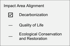
Energy and Atmosphere Prerequisite
ENERGY METERING AND REPORTING
EAp4
REQUIRED
INTENT
To support energy management practices and facilitate identification of ongoing opportunities for energy and GHG emissions savings by tracking and reporting building energy use and demand.
REQUIREMENTS
| Achievement pathways | Points |
|---|---|
Commercial Interiors | N/A |
Energy Monitoring and Recording | |
AND | AND |
Report Energy Data | Report Energy Data |
This prerequisite applies only to project scope including at least 1 of the following:
-
An initial fit-out of project with gross area of at least 10,000 square feet (929 square meters).
-
An alteration replacing electric power distribution for project with gross area of at least 10,000 square feet (929 square meters).
-
New service for electricity, fuel, or thermal energy supplied directly to the tenant by a utility, energy provider, or plant that is not in the building.
-
New on-site renewable energy.
Energy monitoring and recording For initial fit-out of interior spaces with gross area of at least 10,000 square feet (929 square meter), install (or use existing) measurement devices to monitor and record tenant energy use per ANSI/ASHRAE/IES Standard 90.1 .
The referenced version of Standard 90.1 with errata shall be:
o 2019 or later for projects registered before January 1, 2028.
o 2022 or later for projects registered on or after January 1, 2028.
For initial fit-out of interior spaces fewer than 10,000 square feet (929 square meters), or for all alterations replacing electrical power distribution or providing new energy service directly to the
U.S. Green Building Council LEED v5 Reference Guide for Interior Design and Construction, April 2025 Launch Edition 129
PDF Page 141
tenant from a utility, energy provider, or plant that is not in the building, provide measurement devices capable of measuring total energy consumption for each new service, at least monthly.
For new on-site renewable energy generation systems installed in the project scope, provide measurement devices capable of measuring renewable energy generation:
o At 15-minute intervals for tenant spaces larger than 10,000 square feet (929
square meters)
o At least monthly for interior spaces fewer than 10,000 square feet (929 square
meters)
Report energy data Commit to reporting the following data to USGBC at least annually: monthly energy data for 12 consecutive months of total energy consumption for each tenant-metered energy source; tenant-metered on-site renewable energy generation; and, if available, tenant-metered peak electrical demand. This commitment must carry forward for five years or until the building changes ownership or lessee.
REQUIREMENTS EXPLAINED
Applicability The prerequisite requirements only apply to projects of a certain size or extent of construction within the project’s scope of work:
-
Initial buildout with at least 10,000 square feet (929 square meters) of area. Comply with ASHRAE Standard 90.1 .
-
New energy service connections to the tenant. Provide metering capturing monthly energy use.
-
Initial buildout fewer than 10,000 square feet (929 square meters ). Provide monthly electricity metering.
-
Alteration replacing electric power distribution. Provide monthly electricity metering.
-
On-site renewable energy. Provide metering for renewable electricity generation.
All projects referenced above must also report energy data to USGBC. Refer to Table 1 for a summary of the prerequisite energy metering and reporting requirements.
U.S. Green Building Council LEED v5 Reference Guide for Interior Design and Construction, April 2025 Launch Edition 130
PDF Page 142
Table 1. Summary of LEED v5 EAp4: Energy Metering and Reporting Requirements
| Col1 | Alterations of spaces in existing buildings | Initial buildout or addition >= 10,000 sq. ft. | Col4 |
|---|---|---|---|
| Alterations of spaces in existing buildings | Applicability or recording frequency | Referenced 90.1 Sections or LEED-specific | |
| MONITORING (excludes shared base building energy) | |||
New energy service supplied directly to the project space. Total energy by energy source for: • Natural gas • Fuel oil • Propane • District CHW • District steam • District hot water | Monthly | Monthly | 90.1-2019 10.4.6.1 90.1-2022 10.4.7.1 |
Total electricity for project space | Monthly (For new service, or alteration replacing electric power distribution) | 15-minute | 90.1-2019 8.4.3.1 90.1-2022 8.4.3.1 |
| Submetered electricity for project space (except residential dwelling units): • HVAC • Interior lighting • Exterior lighting • Receptacle circuits • Refrigeration systems (90.1- 2022) | N/A | 15-minute | 90.1-2019 8.4.3.1 90.1-2022 8.4.3.1 |
On-site renewable electricity in project scope. | Monthly | 15-minute | LEED-Specific |
REPORTING | |||
| For metered data, commit to annually sharing monthly data with USGBC for: • Energy consumption by energy source • On-site renewable energy generation • Peak electrical demand. | X | X | LEED-Specific |
Capable of creating user reports for consumption and demand at least hourly, daily, monthly, and annually, with system capable of maintaining all data collected for 36 months. | X | 90.1-2019 10.4.6.2 90.1- 2022 10.7.4.2 |
U.S. Green Building Council LEED v5 Reference Guide for Interior Design and Construction, April 2025 Launch Edition 131
PDF Page 143
Energy Monitoring and Recording
ASHRAE STANDARD 90.1, MONITORING AND RECORDING REQUIREMENTS
Initial buildouts with at least 10,000 square feet (929 square meters) of gross building area shall meet ASHRAE Standard 90.1 energy monitoring and recording requirements:
Tenant energy monitoring requirements Electricity meters must be capable of metering and recording total project electricity use at 15minute intervals, excluding shared systems ( ASHRAE 90.1, Sections 8.4.3.1). Exclude electricity from shared HVAC equipment (e.g., a central air handling unit providing supply air to the tenant space) when determining the tenant submetering requirements. Include electricity for system components in the tenant space, such as fan coil units and VAV terminals.
For all other energy sources delivered directly to the project space from outside the building’s site boundary, provide measurement devices capable of monitoring energy use at least monthly. Examples include fuel, district heating, or district cooling delivered from a utility or from a campus energy plant directly to the project space.
Electricity submetering requirements (ASHRAE 90.1 Section 8.4.3.1) Projects must submeter end use electricity data at 15-minute intervals for HVAC, interior lighting, exterior lighting, and receptacle; and if using ASHRAE 90.1-2022 -compliant refrigeration systems.
Electricity end uses that contribute less than 10% of total project electrical load may be excluded. For example, if tenant exterior lighting loads are less than 10% of total tenant electricity use, teams can report exterior lighting with interior lighting. Electricity end uses may also be excluded if the whole-building contribution of the end use comprises less than 10% of whole-building electricity use.
ASHRAE Standard 90.1 reporting ( ASHRAE 90.1, Section s 8.4.3.2 and 90.1-2019 10.4.6.1 or 90.1-2022 10.4.7.1)
The monitoring system must include the capability to report both total and submetered electricity data at least hourly, daily, monthly, and annually, and this data must be accessible to the operators of the space.
Third-party energy monitoring services or applications may be used to comply with the data reporting and data storage requirements.
U.S. Green Building Council LEED v5 Reference Guide for Interior Design and Construction, April 2025 Launch Edition 132
PDF Page 144
Electricity data must be graphically displayed in buildings that are required to have digital control systems - for example, buildings with air handling units with fans > 10 hp (7.5 kW), CHW plants, or hot water plants.
ASHRAE Standard 90.1 version Projects registered before January 1, 2028, must reference the energy monitoring and recording requirements in ASHRAE Standard 90.1-2019 or later version. Projects registered on or after January 1, 2028, must use the slightly augmented energy monitoring and recording requirements from ASHRAE Standard 90.1-2022 . For example, ASHRAE 90.1-2022 adds a submetering requirement for refrigeration systems.
Additional considerations Teams that use a single version of ASHRAE Standard 90.1 for EAp2: Minimum Energy Efficiency, EAp3: Fundamental Commissioning, and EAp4: Energy Metering and Reporting can streamline documentation efforts.
International Energy Conservation Codes (IECC) equivalent standard IECC is an approved equivalent standard for this prerequisite. IECC 2021 requirements can replace ASHRAE Standard 90.1-2019 . IECC 2024 requirements can replace ASHRAE Standard 90.1-2022 .
New energy service connections to the tenant For each new service connection of electricity, fuel, or thermal energy delivered directly to the project space from outside the building’s site boundary, provide measurement devices capable of monitoring energy use at least monthly. Examples include fuel, district heating, or district cooling delivered from a utility or from a campus energy plant to directly to the project space.
Initial buildout less than 10,000 square feet (929 square meters) or alteration replacing electric power distribution Provide measurement devices capable of monitoring monthly electricity use for the project, excluding shared system uses, such as central air handling units.
On-site renewable energy For any new on-site renewable energy system, projects must provide new meters that can measure, record and report on energy generation. For projects that are 10,000 square feet (929 square meters) or greater, record data in 15-minute intervals. Projects that do not meet this threshold can provide data monthly.
U.S. Green Building Council LEED v5 Reference Guide for Interior Design and Construction, April 2025 Launch Edition 133
PDF Page 145
Report Energy Data
Report data annually to USGBC for at least five years, post-occupancy for each energy source that is required to be metered above. Include monthly energy consumption from each metered energy source, including on-site renewable energy generation. For interior buildouts larger than 10,000 square feet (929 square meters), provide monthly peak electric demand. Provide data using the USGBC-provided platform, which includes third-party interfaces with tools such as ENERGY STAR® Portfolio Manager.
For project owners and managers, this valuable data enhances the understanding of building performance. The data also educates occupants and building users on behaviors that impact energy consumption and how positive behavioral changes can create better buildings.
USGBC aims to collect data from all LEED projects. Comparing data across similar project types allows for ongoing benchmarking of high-performing buildings within the LEED portfolio. The data influences refinements and enhancements to future LEED rating system requirements. Data shared with USGBC gives critical insight to the industry on the design, construction, and operation of high-performing buildings.
DOCUMENTATION
| Project types | Options | Paths | Documentation |
|---|---|---|---|
All | All | All | Confirmation of project scope of work. |
All | All | All | Confirmation that the project complies with the necessary 90.1 sections for the project type(s). |
All | All | All | Confirmation that the project includes compliant devices to monitor and record on-site renewable electricity generation (as applicable). |
All | All | All | Evidence of a commitment from the owner or responsible party that the required energy data will be shared with USGBC. |
All | All | All | Confirmation of data-sharing source. |
All | All | All | Note energy sources delivered to the tenant space. |
REFERENCED STANDARDS
-
ASHRAE 90.1-2019 (store.accuristech.com/ashrae/standards/ashrae-90-1-2019-i- p?product_id=2088527)
-
ASHRAE 90.1-2022 (store.accuristech.com/ashrae/standards/ashrae-90-1-2022-i- p?product_id=2522082)
U.S. Green Building Council LEED v5 Reference Guide for Interior Design and Construction, April 2025 Launch Edition 134
PDF Page 146
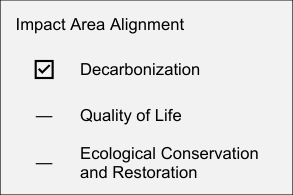
Energy and Atmosphere Prerequisite
FUNDAMENTAL REFRIGERANT MANAGEMENT
EAp5
REQUIRED
INTENT
To reduce GHG emissions from refrigerants by accelerating the phaseout of refrigerants with high global warming potential (GWP) and by reducing refrigerant leakage.
REQUIREMENTS
| Achievement pathways | Points |
|---|---|
Commercial Interiors | N/A |
Option 1. No Refrigerants | |
OR | OR |
Option 2. Refrigerants | Option 2. Refrigerants |
Option 1. No Refrigerants
Do not use refrigerants in the project.
OR
Option 2. Refrigerants
Meet the following requirements for refrigerant-containing equipment installed, replaced, or altered in the project scope of work:
-
Complete refrigerant inventory : Complete an inventory of the refrigerant-containing equipment installed within the project scope of work and any existing equipment under control of the tenant. The inventory shall include the refrigerant type, GWP, amounts of refrigerants contained in each, and the total GWP of all refrigerants.
-
Do not use hydrochlorofluorocarbon (HCFC) refrigerants in new equipment.
-
Evaluate available alternatives during the design process for any refrigerants with GWP
-
-
Leak check and repair. Prior to substantial completion, check both new and existing refrigerant-containing equipment for refrigerant leaks and repair all leaks identified. For systems with field-assembled joints, perform a leak check, vacuum check, and pressure check prior to charging with refrigerant.
U.S. Green Building Council LEED v5 Reference Guide for Interior Design and Construction, April 2025 Launch Edition 135
PDF Page 147
NOTE: The refrigerant inventory may be documented for the tenant or for the entire building, provided that these include tenant systems.
REQUIREMENTS EXPLAINED
Option 1 applies to projects without refrigerants. Projects with refrigerants must follow Option 2.
Option 1. No Refrigerants
Projects with no new or reused refrigerant-containing equipment under the control of the tenant automatically meet the prerequisite.
Option 1 criteria does not preclude the use of equipment containing less than 0.5 lbs. (225 g), such as standard residential refrigerators, small wine coolers, or portable space dehumidifiers.
OR
Option 2. Refrigerants
Teams pursuing this path must avoid HCFC refrigerants, analyze alternatives for refrigerants with a GWP greater than 700, inventory refrigerant-using equipment, and ensure no leaks from refrigerant-containing equipment.
No HCFC refrigerants New equipment installed within the project scope of work cannot use HCFC refrigerants, which cause damage to the ozone layer and often have very high GWP.
Developed and developing countries In developed countries, government regulations have already phased out HCFC refrigerants for new equipment per the Kigali Amendment to the Montreal Protocol [36] .
In developing countries, teams must take precautions to limit selections to equipment that does not use HCFCs . Equipment specifications must clearly disallow HCFCs such as R-22, used in air conditioners, or R-123, commonly used in chillers.
Evaluation of alternative refrigerants GWP measures the relative contribution of a substance toward heating the atmosphere compared to the same mass of carbon dioxide (CO2). For example, R-410A with a GWP of 2,088 traps 2,088 times more heat in the atmosphere than CO2.
36 “About Montreal Protocol”, UN Environment Programme, accessed March 31, 2025, https://www.unep.org/ozonaction/who-weare/about-montreal-protocol.
U.S. Green Building Council LEED v5 Reference Guide for Interior Design and Construction, April 2025 Launch Edition 136
PDF Page 148
This prerequisite references 100-year GWPs assessed in accordance with the IPCC Fourth Assessment report or later.
Reviewing refrigerant properties during the design process allows teams to address high GWP refrigerants and find suitable alternatives before construction begins. As the industry continues to develop new alternative refrigerants, projects can find cost-effective solutions that also meet efficiency and environmental goals.
Equipment with GWP > 700 During the design process, if the specifications reference equipment with refrigerant GWP exceeding 700 or do not specify the refrigerant(s) that can be used, develop a list of alternative equipment options with refrigerant GWP less than or equal to 700. Review all proposed options with the owner.
Refrigerant properties vary in efficiency, toxicity, flammability, volumetric capacity, and pressure ratings. Not all refrigerants are interchangeable within a piece of equipment or in a system. Therefore, completing this evaluation early in design provides the most benefit.
For applications where GWP less than 700 is impractical, consider the use of reclaimed refrigerant instead of newly manufactured virgin refrigerant, to limit overall impact.
Table 1 provides a common list of refrigerants and their GWP, adapted from the Net Zero Carbon Guide [37] and The Heating, Refrigeration and Air Conditioning Institute of Canada (HRAI). [38]
Table 1. Common refrigerants and their applications
| Refrigerant | Classification | GWP | Common System Applications |
|---|---|---|---|
R404A | HFC blend | 3,920 | Low-Medium Temperature Commercial Refrigeration Low-Medium Temperature Industrial Refrigeration Ice Machines |
| R410A | HFC | 2,088 | Conventional VRF systems Heat Pumps Chillers |
| R22 | HCFC | 1,810 | Commercial Refrigeration Industrial Refrigeration Commercial Air Conditioning Residential Air Conditioning |
| R134a | HFC | 1,430 | Heat Pumps |
37 “Refrigerants and their Contribution to Global Warming”, Net Zero Carbon Guide, accessed March 31, 2025, https://www.netzerocarbonguide.co.uk/guide/designing-and-building/heating-your-building/refrigerants-and-their-contribution-to- global-warming. 38 “Refrigerant Table: Explanation and Glossary of Terms”, The Heating, Refrigeration, and Air Conditioning Institute of Canada (HRAI), accessed March 31, 2025, https://www.hrai.ca/uploads/userfiles/files/refrigerant_table_June2019.pdf.
U.S. Green Building Council LEED v5 Reference Guide for Interior Design and Construction, April 2025 Launch Edition 137
PDF Page 149
| Refrigerant | Classification | GWP | Common System Applications |
|---|---|---|---|
Chillers | |||
| R32 | HFC | 633 | Hybrid VRF systems Heat Pumps Chillers |
| R513A | HFO | 573 | Medium Temperature Commercial Refrigeration Medium Temperature Industrial Refrigeration Chillers Air Conditioning Units Heat Pumps |
| R600 (Butane) | HC | 4 | Heat Pumps Chillers |
R290 (Propane) | Natural | 3 | Commercial Refrigeration Heat Pumps Chillers |
| R1234ze | HFO | <1 | Heat Pumps Chillers |
| R744 (CO2) | Natural | 1 | Heat Pumps |
R717 (NH4, ammonia) | Natural | 0 | Heat Pumps |
Equipment inventory Project teams must identify all refrigerant-containing equipment in the LEED ID+C: Commercial Interiors project, including new equipment installed in the project scope and any existing equipment within the project boundary, owned or controlled by the tenant. Equipment that contains less than 0.5 pounds (225 grams) of refrigerant, such as standard residential refrigerators in dwelling units, can be excluded from the calculations.
Manage the inventory during the construction phase. If equipment substitutions occurred during the submittal and procurement phases, update the inventory to reflect the actual installed equipment.
Table 2 is a sample and noncomprehensive list of the types of refrigerant-using equipment that may be included in a project’s scope of work.
A refrigerant inventory for the complete building is acceptable in lieu of a project-specific inventory. Ensure that the inventory is updated with any new equipment installed within the project scope.
Additional considerations — equipment inventory Completing the inventory in the Construction Documents phase provides owners and design professionals with a complete understanding of the future climate impacts.
U.S. Green Building Council LEED v5 Reference Guide for Interior Design and Construction, April 2025 Launch Edition 138
PDF Page 150
Table 2. Refrigerant-containing equipment
| Application | Equipment/System Type |
|---|---|
HVAC, Space Cooling Equipment | Stationary Air Conditioners and Heat Pump Chillers Computer Room Air Conditioning Units |
| Service Water Heaters | Heat pump Service Water Heaters |
Retail | Food Refrigeration Cold Storage |
| Commercial | Vending Machines Ice Machines |
| Industrial Process Refrigeration | Process Chillers Ice Rink Chillers Other Process Refrigeration |
Data collection For each piece of equipment, document the refrigerant properties, including type of refrigerant, refrigerant GWP (GWPREFRIGERANT), and refrigerant charge (Rc).
When the project design includes field-assembled refrigerant piping with long pipe lengths or large pressure drops (e.g., variable refrigerant flow (VRF) systems, industrial process equipment), teams must account for additional required Rc in the calculations per manufacturer’s specifications or confirm that the manufacturer’s default charge or referenced submittals already account for this additional charge.
Calculate the total equipment GWP for each equipment using Equation 1.
Equation 1. GWPEQUIPMENT calculation
calculation
𝐸 𝐸 𝐸 𝐸 𝐸𝐸 [= 𝑅𝑅] 𝐶𝐶 [× 𝐺] 𝑅 𝑅 𝑅 𝑅 𝑅 𝑅𝑅 𝐺 𝐺𝐺 𝐺𝐺
The project’s total GWP is the sum of the GWP s for all refrigerant-using equipment in the project:
Equation 2. GWPTOTAL calculation
𝑇 𝑇 𝑇𝑇 𝐸 𝑈𝑈𝐼 𝐼 𝐼 𝐺 𝐺𝐺 = � 𝐺 𝐺𝐺
Determine the weighted average GWP for the project by dividing the project’s total GWP by the sum of refrigerant charge for all equipment:
Equation 3. Weighted average GWP calculation
𝑇 𝑇 𝐿
𝐺
𝑊 𝑊 ℎ𝑡 𝑡𝑡 𝐴 𝐴 𝐴 𝐴𝐴 𝐺 𝐺𝐺 = [𝐺] 𝐶
𝛴𝑅
U.S. Green Building Council LEED v5 Reference Guide for Interior Design and Construction, April 2025 Launch Edition 139
PDF Page 151
Leak check and repair Perform leak checks for all refrigerant-containing equipment in the project, including new and existing equipment. Field-installed piping requires vacuum and pressure testing during the installation process per the International Mechanical Code Chapter 11 [39] , EPA Clean Air Act Section 608 [40] , European Union F-Gas Regulations [41], or similar referenced standards.
For existing systems or self-contained systems, leak check inspections may leverage electronic leak detectors, data from the building automation system, visual inspections for oil residue on joints or for bubbling from leaks after applying soapy water, audible detection of hissing or bubbling sounds, and/or pressure testing.
DOCUMENTATION
| Project types | Options | Paths | Documentation |
|---|---|---|---|
All | Option 1. No Refrigerants | All | Description of the cooling and heating systems used for the project. Confirmation that no refrigerants are used within the project boundary and how the project meets cooling, heating, and other project loads without refrigerants. |
All | Option 2. Refrigerants | All | Narrative summarizing the evaluation of available alternatives for any refrigerant with a GWP >700. Include a list of the original selected refrigerants as compared to the recommended alternative. |
All | Option 2. Refrigerants | All | Refrigerant inventory with complete list of all refrigerant- containing equipment. Each piece of equipment shall include the equipment type, refrigerant type, GWP, and Rc. |
All | Option 2. Refrigerants | All | Total GWP of all refrigerants. |
All | Option 2. Refrigerants | All | Narrative describing the refrigerant leak check evaluation. Include confirmation that the leak check has occurred for all equipment. |
All | Option 2. Refrigerants | All | Attestation that all leaks are repaired prior to charging with refrigerant. |
REFERENCED STANDARDS
-
EPA 2023 AIM ACT Technology Transitions Rule (epa.gov/climate-hfcs- reduction/regulatory-actions-technology-transitions)
-
EPA regulations - 40 CFR Part 82, Subpart F (ecfr.gov/current/title-40/chapter-I/subchapter- C/part-82/subpart-F)
-
International Mechanical Code Chapter 11 (codes.iccsafe.org/content/IMC2021P3)
39 “International Mechanical Code Chapter 11”, ICC, accessed March 31, 2025, https://codes.iccsafe.org/content/IMC2021P3. 40 “EPA Clean Air Act Section 608, U.S EPA”, accessed March 31, 2025, https://www.epa.gov/section608/section-608-clean-air-act. 41 “European Union F-Gas Regulations”, EUR-Lex, European Union, accessed March 31, 2025, https://eurlex.europa.eu/eli/reg/2024/573/oj.
U.S. Green Building Council LEED v5 Reference Guide for Interior Design and Construction, April 2025 Launch Edition 140
PDF Page 152
-
EPA Clean Air Act Section 608 (epa.gov/section608/section-608-clean-air-act)
-
European Union F-Gas Regulations (eur-lex.europa.eu/eli/reg/2024/573/oj)
U.S. Green Building Council LEED v5 Reference Guide for Interior Design and Construction, April 2025 Launch Edition 141
PDF Page 153
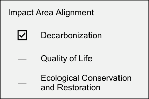
Energy and Atmosphere Credit
ELECTRIFICATION
EAc1
1–5 points
INTENT
To encourage buildings to be designed so that they do not depend on burning fuel on-site, leading to better indoor and outdoor air quality and to low-carbon operations as the grid decarbonizes.
REQUIREMENTS
| Achievement pathways | Points |
|---|---|
Commercial Interiors | 1–5 |
Option 1. No On-Site Combustion—Base Building and Tenant Systems | 5 |
OR | |
Option 2. No On-Site Combustion Except at Low Temperatures—Base Building and Tenant Systems | 1–5 |
Path 1. Space Heating | 2 |
AND/OR | |
Path 2. Service Water Heating | 1 |
AND/OR | |
Path 3. Cooking and Other Process Loads | 1–2 |
Option 3. No On-Site Combustion, Limited Scope | 1–3 |
OR | |
Option 4. Base Building Documentation and Tenant Compliance | 5 |
Option 1. No On-Site Combustion — Base Building and Tenant Systems (5 points)
Design and operate the project from start-up with no on-site combustion except for emergency support systems.
The combined weighted average equipment efficiency for space heating and service water heating (SWH) must be at least 1.8 Coefficient of Performance (COP) for initial build-out construction or at least 1.2 COP for alterations.
The following equipment may be excluded from the COP determination:
-
Space heating equipment in climate zones 0–2
-
Supplemental heating equipment designed only for operation at low temperatures
U.S. Green Building Council LEED v5 Reference Guide for Interior Design and Construction, April 2025 Launch Edition 142
PDF Page 154
- SWH equipment in nonresidential spaces complying with the point-of-use water heater criteria in ASHRAE 90.1-2022, Section 11.5.2.3.3, W05, without exceptions
OR
Option 2. No On-Site Combustion Except at Low Temperatures—Base Building and Tenant Systems (1–5 points)
Pursue any combination of the following paths for a maximum of 4 points:
PATH 1. SPACE HEATING (2 POINTS)
Design space heating to be capable of operating without on-site combustion except at low temperatures. Projects in climate zones 3 and above must have a weighted average space heating equipment efficiency of at least 1.8 COP for initial build-out construction or at least 1.2 COP for alterations.
The following equipment may be excluded from the COP determination:
- Supplemental heating equipment designed only for operation at low temperatures
AND/OR
PATH 2. SWH (1 POINT)
Design SWH systems to be capable of operating without on-site combustion except at low temperatures. Projects with total SWH capacity exceeding 34,000 Btu/hr (10 kW) must have a weighted average service hot water equipment efficiency of at least 1.8 COP for initial build-out construction or at least 1.2 COP for alterations.
The following equipment may be excluded from the COP determination:
-
SWH equipment in nonresidential spaces complying with the point-of-use water heater criteria in ASHRAE 90.1-2022, Section 11.5.2.3.3, W05, without exceptions
-
Supplemental heating equipment designed only for operation at low temperatures
AND/OR
PATH 3. COOKING AND OTHER PROCESS LOADS (1–2 POINTS)
Design cooking, laundry, process equipment, and on-site power generation except emergency support systems to be capable of operating without on-site combustion.
Not in scope (1 point)
- Cooking, laundry, or process heating systems are not in project scope of work.
U.S. Green Building Council LEED v5 Reference Guide for Interior Design and Construction, April 2025 Launch Edition 143
PDF Page 155
In scope (2 points)
- Cooking, laundry, process heating, process drying, and/or on-site power generation are installed within the project scope.
The following equipment may be excluded:
- Process heating equipment designed for operation at low temperatures
Option 3. No On-Site Combustion, Limited Scope (1–3 points)
For the project scope of work:
-
Do not install on-site combustion equipment in the project scope of work.
-
Combined weighted average equipment efficiency for new space heating and SWH must be at least 1.8 COP for initial build-out construction or at least 1.2 COP for alterations.
The following equipment may be excluded from the COP determination:
-
Space heating equipment in climate zones 0–2
-
Supplemental heating equipment designed only for operation at low temperatures
-
SWH equipment in nonresidential spaces complying with the point-of-use water heater criteria in ASHRAE 90.1-2022, Section 11.5.2.3.3, W05, without exceptions
Points are awarded according to Table 1 based on the minimum project scope of work.
Table 1. Points for no on-site combustion, limited scope
| Minimum project scope of work | Points |
|---|---|
One or more cooking, heating, SWH, or process heating systems | 1 |
At least 20% of the project’s peak combined heating and SWH load, or all commercial cooking equipment | 2 |
At least 50% of the project’s peak combined heating and SWH load, or all commercial cooking equipment | 3 |
OR
Option 4. Base Building Documentation and Tenant Compliance (5 points)
Points are awarded according to Table 2. Locate in a building that has documented a LEED credit per Table 2.
AND/OR
Meet the following criteria per system type in the project scope of work. The system types are defined as:
U.S. Green Building Council LEED v5 Reference Guide for Interior Design and Construction, April 2025 Launch Edition 144
PDF Page 156
-
Space heating
-
SWH
-
Cooking and other process loads
-
Criteria per system type:
- Do not install on-site combustion equipment.
AND
- Combined weighted average equipment efficiency for space heating system type and SWH system type must be at least 1.8 COP for initial build-out construction or at least 1.2 COP for alterations.
The following equipment may be excluded from the COP determination:
-
Space heating equipment in climate zones 0–2
-
Supplemental heating equipment designed only for operation at low temperatures
-
SWH equipment in nonresidential spaces complying with the point-of-use water heater criteria in ASHRAE 90.1-2022, Section 11.5.2.3.3, W05, without exceptions
Table 2. Points for achievement of base building performance and tenant performance
| Base building documentation | Col2 | Col3 | Minimum system types in project scope complying with criteria | Points awarded |
|---|---|---|---|---|
LEED rating system(s) | LEED EA credit name and credit option | Base building minimum threshold | Base building minimum threshold | Base building minimum threshold |
LEED v5 BD+C | EAc1: Electrification | 1 point | None | 1 |
LEED v5 BD+C | EAc1: Electrification | 2 points | None | 2 |
LEED v5 BD+C | EAc1: Electrification | 3 points | At least one, or all systems in scope | 3 |
LEED v5 BD+C | EAc1: Electrification | 4 points | At least two, or all systems in scope | 4 |
LEED v5 BD+C | EAc1: Electrification | 5 points (NC) 4 points (CS) | All systems in scope | 5 |
| LEED v5 O+M: Existing Buildings | EAc1: GHG Emissions Reduction Performance, Option 1,GHG From On-Site Combustion | 2 points | None | 1 |
| LEED v5 O+M: Existing Buildings | EAc1: GHG Emissions Reduction Performance, Option 1,GHG From On-Site Combustion | 3 points | None | 2 |
| LEED v5 O+M: Existing Buildings | EAc1: GHG Emissions Reduction Performance, Option 1,GHG From On-Site Combustion | 4 points | At least one, or all systems in scope | 3 |
| LEED v5 O+M: Existing Buildings | EAc1: GHG Emissions Reduction Performance, Option 1,GHG From On-Site Combustion | 5 points | At least two, or all systems in scope | 4 |
| LEED v5 O+M: Existing Buildings | EAc1: GHG Emissions Reduction Performance, Option 1,GHG From On-Site Combustion | 6 points | All systems in scope | 5 |
For all options
Equipment efficiency (for Options 1 and 2) Determine weighted average COP using either of the following:
U.S. Green Building Council LEED v5 Reference Guide for Interior Design and Construction, April 2025 Launch Edition 145
PDF Page 157
-
Equipment efficiencies at rated conditions. For equipment with multiple rated conditions, use the rating closest to 17°F (-9°C) OA db, 32°F (0°C) entering liquid temperature, or 44°F (6°C) heating source leaving liquid temperature.
- Annual average COP calculated with an energy simulation.
District energy Projects with district energy must comply with the requirements of this credit at the district facility or see additional guidance for interpretation of credit requirements.
Fuel cells Fuel cells using fossil fuel are ineligible for credit.
Low temperatures “Low temperatures” refers to outside air dry-bulb temperatures (OA db) below 20°F (-6.5°C).
REQUIREMENTS EXPLAINED
This credit rewards decarbonization achieved through electrification of building systems traditionally fueled with on-site combustion, including space heating, SWH, cooking, and other process equipment.
Projects may choose between Options 1–4. For all options, electrified space heating and SWH equipment must meet efficiency criteria to limit undue burden on the electric power grid. Refer to the Weighted Average COP section for further guidance.
The requirements for Options 1, 2, and 4 encompass base building systems serving the project and systems within the project scope. These options are most appropriate for projects with the majority of HVAC and SWH capacity in the project scope of work or projects that intentionally locate in electrified or partially electrified buildings.
-
Maximum points are available under Option 1 to projects that fully electrify all base building and project systems.
-
Option 2 selectively rewards electrification per system category for heating, SWH, and cooking and other process loads; and affords flexibility for a hybrid design capable of limiting on-site combustion to low-temperature operation.
-
For projects located in buildings certified under LEED v5 (either LEED BD+C or LEED AP O+M), Option 4 provides a streamlined documentation method for demonstrating project performance. Requirements for Option 4 are similar to those in Options 1 and 2; however, for existing buildings using Option 4, the efficiency requirements only apply to elements within the project scope.
U.S. Green Building Council LEED v5 Reference Guide for Interior Design and Construction, April 2025 Launch Edition 146
PDF Page 158
Option 3 solely addresses equipment installed or replaced in the project scope of work and therefore is appropriate for projects where base building systems serving the project are not electrified.
Option 1. No On-site Combustion — Base Building and Tenant Systems
Electrification Projects designed to operate entirely without on-site combustion for all building systems serving the project offer the greatest emission reduction through electrification. Projects pursuing this option must eliminate on-site combustion from the project system design and operations. If a tenant space is designed without on-site combustion, but fossil fuels are used for any base building system serving the project (such as a central hot water boiler, water heater, or shared air handling unit with fossil fuel furnace), the LEED ID+C: Commercial Interiors project cannot pursue this option. Refer to the Exemptions section for limited exceptions.
Efficiency Combined weighted average equipment efficiency for applicable space heating and SWH equipment serving the project must be at least 1.8 COP for initial buildout or at least 1.2 COP for projects in existing buildings. Refer to the guidance in the Weighted Average COP section.
Option 2. No On-site Combustion Except at Low Temperatures — Base Building and Tenant Systems
For Option 2, teams may apply any combination of Path 1, Path 2, and Path 3, which separately address electrification of space heating, service hot water heating, and cooking and other process systems serving the project, respectively.
PATH 1. SPACE HEATING
Electrification All space heating systems serving the project must be capable of operating without on-site combustion, except in low-temperature operating mode at or below 20°F (-6.5 °C). Electrified space heating equipment serving the project must be designed with sufficient capacity to meet the entire project space heating load at the system, zone and space levels for outdoor temperatures above 20°F (-6.5 °C) or the project’s design heating temperature. Hybrid designs with fuel/electric equipment must have a sequence of operations with at least one allelectric operating mode available above 20°F (-6.5 °C).
Efficiency Space heating equipment serving the project in climate zones 3 and above must have a weighted average equipment efficiency of at least 1.8 COP for initial buildout, or at least 1.2
U.S. Green Building Council LEED v5 Reference Guide for Interior Design and Construction, April 2025 Launch Edition 147
PDF Page 159
COP for projects in existing buildings. Refer to the Weighted Average COP section for calculations and exclusions from COP determination.
Projects without heating Credit achievement is automatic for projects that have no space heating from base building systems or from equipment installed in the project scope.
PATH 2. SWH
Path 2 requirements apply to all SWH use for the project, including for shared restrooms or shower facilities that are not in the project boundary but are accessed regularly by occupants of the space.
SWH is the supply of hot water for purposes other than space heating and process applications. It is primarily used for handwashing, showering, and cleaning.
Electrification All SWH serving the project must be capable of operating without on-site combustion, except in low-temperature operating mode at or below 20°F (-6.5 °C).
Electrified SWH equipment must be designed with sufficient capacity and distribution capability to provide all necessary SWH at outdoor temperatures above 20°F (-6.5 °C) or the project’s design heating temperature.
Efficiency If the project’s total SWH load exceeds 34,000 Btu/h (10 kW), the SWH systems serving the project space must use efficient heat pump technology to achieve a weighted average SWH equipment efficiency of at least 1.8 COP for initial buildout, or at least 1.2 COP for existing buildings; or must generate at least 40% of the project’s total SWH load with solar thermal energy.
Point of use SWH equipment in nonresidential spaces may be excluded from the weighted average COP determination if it meets ASHRAE 90.1-2022, Section 11.5.2.3.3, W05, without exceptions. Refer to the Weighted Average COP section for calculations and exclusions from COP determination.
PATH 3. COOKING AND OTHER PROCESS LOADS
This path encourages design teams to eliminate on-site combustion from cooking, laundry, pool or spa heating, power generation, and all other process applications that traditionally use fuel.
Examples of other process applications commonly addressed through electrification include process heating, process drying, pre-conditioned air or 400 Hz systems in airports, and
U.S. Green Building Council LEED v5 Reference Guide for Interior Design and Construction, April 2025 Launch Edition 148
PDF Page 160
powering of vehicles or equipment operated exclusively on the project site (e.g., forklifts or golf carts).
All process systems serving the project must be capable of operating without on-site combustion, except in low-temperature operating mode for outdoor dry-bulb temperatures at or below 20°F (-6.5 °C). This requirement extends to any process heating or on-site electricity generation supplied from the base building systems to the project.
Exception Clothes washers supplied with SWH from the base building systems are not required to show compliance for the hot water connection.
Not in scope One point is rewarded to projects that do not have cooking, laundry, and/or process heating systems in the project scope of work, provided that any existing cooking or other process equipment reused in the project, and any process heating or on-site electricity systems serving the project, meet the criteria above.
In scope A second point is available under this path for projects that electrify process systems within the scope of work, since this contributes more heavily to overall decarbonization achieved for the project. One of the following must be in scope:
-
Cooking . Cooktops, ovens, fryers, griddles, or any other commercial or residential cooking equipment traditionally fueled by natural gas or other fossil fuels
-
Laundry . Clothes dryers or clothes washers with hot water supply free of on-site combustion
-
Process heating equipment . Industrial boilers or furnaces
-
Drying equipment used for industrial processes
-
On-site power generation such as solar PV
Other cooking or process equipment that can only be powered by electricity such as microwaves cannot be used to achieve the 2nd point.
Option 3. No On-site Combustion, Limited Scope
This option is intended for projects with limited scope that do not install systems using on-site combustion. Combined weighted average equipment efficiency for space heating and SWH systems installed in the project scope of work must be at least 1.8 COP for initial buildout or at least 1.2 COP for projects in existing buildings. Refer to the guidance in the Weighted Average COP section.
U.S. Green Building Council LEED v5 Reference Guide for Interior Design and Construction, April 2025 Launch Edition 149
PDF Page 161
Project scope of work Projects must fully electrify any systems in scope. Refer to the Exemptions section for limited exceptions.
Minimum project scope for projects without commercial cooking equipment must include installation of at least one space heating, SWH, laundry, or process heating system for one point; at least 20% of the project’s combined heating and SWH load for two points; or at least 50% of the project’s combined heating and SWH load for three points.
For projects that install electrified commercial cooking equipment, such as cooktops, ovens, fryers, griddles, or other equipment traditionally fueled by natural gas or other fossil fuels, the maximum three points are awarded. This does not apply to cooking appliances that can only be powered by electricity such as microwaves.
Option 4. Base Building Documentation and Tenant Compliance
Prioritizing a LEED-certified base building provides tenants the opportunity to leverage integrated sustainable elements and improve their tenant space.
LEED-certified base building requirements The project must be in a LEED v5 base building, certified under any LEED v5 rating system (LEED BD+C: New Construction, LEED BD+C: Core and Shell, or LEED AP O+M). The project must have achieved points for EAc1: Electrification (LEED BD+C: New Construction, LEED BD+C: Core and Shell) or EAc1: GHG Emissions Reduction, Option 1 . GHG from on-site combustion (LEED AP O+M).
Point thresholds Interiors projects achieve points based on both the base building achievements, and additional considerations within the project scope of work. Maximum credit achievement is awarded to project’s that achieve full electrification of the base building and tenant systems and utilize efficient heat pump equipment for most of the space heating and SWH capacity installed in the project scope.
Example 1 . Base building with no tenant scope The project is an initial buildout of an office space in a base building certified with LEED v5 BD+C: Core and Shell that achieved two points under EAc1: Electrification. No new space heating, SWH, cooking, or process equipment
U.S. Green Building Council LEED v5 Reference Guide for Interior Design and Construction, April 2025 Launch Edition 150
PDF Page 162
is in the project scope. Therefore, all systems in scope comply with the criteria.
The LEED ID+C: Commercial Interiors project would earn two points for Option 4, because the base building only earned two points.
Example 2 . Base building with tenant scope Referring to Example 1 above, the project scope is amended to include new point-of-use SWH equipment that meets ASHRAE 90.1-2022, Section 11.5.2.3.3. The LEED ID+C: Commercial Interiors project earns two points for Option 4, because the base building only earned two points.
Example 3 . Base building with electrification of some tenant systems The project is an initial buildout of an office space in a base building certified with LEED v5 BD+C: Core and Shell that achieved four points under EAc1: Electrification.
The project scope includes installation of: Fully electrified space heating equipment with a weighted average equipment efficiency of 1.8 COP, meeting the credit criteria for space heating.
Electric resistance storage water heating equipment with capacity totaling 20 kW which does not meet the criteria for efficiency and cannot achieve a combined weighted average 1.8 COP when paired with space heating.
New gas cooktop that does not meet the cooking and other process loads criteria.
The LEED ID+C: Commercial Interiors project earns three points for Option 4 because the base building earned at least three points and the tenant met the project scope requirements for one system type in scope.
Example 4 . Base building with full points achieved and fully compliant tenant scope Five points are achieved for an initial buildout of an office space in a base building certified with LEED v5 BD+C: Core and Shell that achieved four points under EAc1: Electrification, where all systems installed in the Interiors scope meet the minimum system type criteria.
U.S. Green Building Council LEED v5 Reference Guide for Interior Design and Construction, April 2025 Launch Edition 151
PDF Page 163
Weighted Average COP
Minimum weighted average COP criteria is predicated on a design that uses heat pump technology instead of inefficient electric resistance heating to meet most of the project’s space heating and SWH loads for new systems; or approximately 20% of the project’s space heating and SWH loads for existing buildings. This limit increased grid peak demand associated with electrification.
Exclusions from weighted average COP determination The following equipment may optionally be excluded from the weighted average COP determination:
-
Space heating equipment in climate zones 0–2 . This equipment is not required to be included because electric resistance heating contributes much less to peak grid load in hot climates than in cooler climates. To determine the project’s climate zone, refer to ASHRAE Standard 169, Climatic Data for Building Design Standards [42] .
-
Supplemental heating equipment designed only for operation at or below 20°F (- 6.5 °C) . This equipment is not required to be included because it can skew the average efficiencies calculated using capacity weightings of rated efficiencies. This exclusion applies to supplemental or auxiliary electric heating used for space heating or SWH, as well as fuel used for low temperature operation for space heating or SWH in Option 2.
-
Point of use SWH equipment in nonresidential spaces meeting ASHRAE 90.1-2022, Section 11.5.2.3.3, W05, without exceptions . For nonresidential projects with low SWH demand distributed throughout the building, electric point-of-use water heaters are often more appropriate than centralized heat pump equipment and negligibly increase peak electric demand. Therefore, teams may exclude point-of-use water heaters in nonresidential spaces from the COP determination if they comply with ASHRAE 90.1-2022 11.5.2.3.3, W05 without exception.
Nonresidential SWH equipment that does not comply with the ASHRAE 90.1-2022 11.5.2.3.3 criteria must be included in the determination of weighted average COP. For example, storage water heaters supplying showers or commercial kitchen operations must be included in the determination of weighted average COP.
This exception does not apply to equipment in residential spaces, due to higher SWH demand for these space types.
42 “ASHRAE Standard 169 Climatic Data for Building Design Standards”, ASHRAE, accessed March 31, 2025, https://www.ashrae.org/file%20library/technical%20resources/standards%20and%20guidelines/standards%20addenda/169_2020_a _20211029.pdf.
U.S. Green Building Council LEED v5 Reference Guide for Interior Design and Construction, April 2025 Launch Edition 152
PDF Page 164
- SWH equipment for projects with total SWH capacity less than 34,000 Btu/h (10 kW). This refers to total capacity necessary to meet project loads, regardless of whether the equipment is installed in the project scope of work.
Projects are not required to calculate the weighted average COP if all equipment meets one of the criteria above. For example, no minimum COP is required for a non-residential project in climate zone 1 with point-of-use water heating for 100% of its SWH load per ASHRAE 90.1- 2022 11.5.2.3.3.
When heat pump space heating is installed for a project in climate zones 0–2 or heat pump SWH is installed for projects with total SWH load less than 34,000 Btu/h (10 kW), the analyst may include all heating and SWH equipment in the calculations to demonstrate the required COP.
Included equipment for weighted average COP determination All equipment not specifically excluded above must be included in the weighted average COP determination.
For Options 1 and 2, include all applicable equipment serving the project, including base building equipment and equipment installed within the project scope.
- Option 1. No On-Site Combustion. Base Building and Tenant Systems . Include all space heating and SWH serving the project, except equipment specifically excluded above. Option 2. No On-Site Combustion Except at Low Temperatures . Base Building and Tenant Systems. Projects pursuing both Path 1 and Path 2 may optionally show a combined weighted average equipment efficiency for space heating and SWH, rather than demonstrating weighted average COP per system type.
o Path 1. Space Heating . Include all space heating equipment serving the project,
both in the base building and in the project boundary, except equipment specifically excluded above.
o Path 2. SWH . Include all SWH equipment serving the project, except equipment
specifically excluded above.
-
Option 3. No On-Site Combustion, Limited Scope . Include all space heating and SWH equipment included in the project scope of work, except equipment specifically excluded above.
-
Option 4. Base building documentation and tenant compliance . Include space heating and SWH installed in the project scope if demonstrating compliance with the “Criteria per system type.”
U.S. Green Building Council LEED v5 Reference Guide for Interior Design and Construction, April 2025 Launch Edition 153
PDF Page 165
Methodologies For weighted average COP determination Projects may determine weighted average COP using a streamlined method, rated capacities, or energy simulation.
METHOD 1. STREAMLINED WEIGHTED AVERAGE COP DETERMINATION The streamlined method conservatively estimates compliance based on ASHRAE 90.1, Section 6.8 mandatory rated heating efficiencies of at least 2.0 COP for heat pumps and heat recovery chillers.
o To confirm a weighted average COP of at least 1.8, document that at least 80% of
equipment capacity consists of heat pumps, heat recovery chillers, or solar heating.
o To confirm a weighted average COP of at least 1.2, document that at least 20% of
equipment capacity consists of heat pumps, heat recovery chillers, or solar heating.
For Options 3 and 4, assess compliance based on total installed equipment capacity. For projects served by centralized base building equipment that is shared with other spaces, either calculate the weighted average COP separately for base building systems and for project-installed systems or prorate the base building equipment capacity to the project based on the percentage of design load serving the project or based on proportion of gross floor area.
For Options 1 and 2, assess compliance based on the total capacity serving the project.
METHOD 2. ENERGY SIMULATION Calculate the COP by dividing total annual heating generation by total annual heating energy consumption (using consistent units in numerator and denominator) per Equation 1.
Equation 1. COP calculation using energy simulation data
[𝑡] [𝑡][ 𝑎] [𝑎] [𝑎] [ ℎ𝑒] [𝑒] [𝑒] [ 𝑔] [𝑔] [𝑔] [𝑔] [𝑔] 𝐶 𝐶𝐶= [𝑡]
𝑡 𝑡 𝑡 𝑎 𝑎 𝑎 ℎ𝑒 𝑒 𝑒 𝑐 𝑐 𝑐 𝑐 𝑐
𝑡 𝑡 𝑡 𝑎 𝑎 𝑎 ℎ𝑒 𝑒 𝑒 𝑐 𝑐 𝑐 𝑐 𝑐 𝑐
Ensure that all applicable space heating and SWH energy used at the plant, system, and zone levels are included.
Projects may use any of the following to document the weighted average COP:
- Modeling used for EAp2: Minimum Energy Efficiency
o ASHRAE 90.1, Appendix G Performance Rating Method, proposed model
o ASHRAE 90.1, ECB method design energy cost model
U.S. Green Building Council LEED v5 Reference Guide for Interior Design and Construction, April 2025 Launch Edition 154
PDF Page 166
o TSPR. Simplified model from ASHRAE 90.1-2022, Section 6.6.2.2 Mechanical
System Performance Rating Method. This only shows space heating efficiency. SWH compliance must be demonstrated using one of the other methods.
-
Energy simulation used to document local code compliance
-
Simplified energy simulation used to estimate energy consumption for EAp1: Operational Carbon Projection and Operational Carbon Projection, provided that the model inputs include sufficient detail relevant to equipment efficiencies, capacities, and loads estimations
METHOD 3. RATED CAPACITIES Calculate weighted average COP based on the capacity-weighted average rated equipment efficiency per Equation 2.
Equation 2. Weighted average COP
=
∑𝑟 𝑟 𝑟 𝑐 𝑐 𝑐 𝑐 𝑜 𝑒 𝑒ℎ 𝑒 𝑒 𝑒 𝑒 𝑒 × 𝑟 𝑟 𝑟 𝐶 𝐶 𝑜 𝑒 𝑒ℎ 𝑒 𝑒 𝑒 𝑒 𝑒
𝑡 𝑡 𝑡 𝑟 𝑟 𝑟 𝑒 𝑒 𝑒 𝑒 𝑒 𝑐 𝑐 𝑐 𝑐 𝑜 𝑎 𝑎 𝑒 𝑒 𝑒 𝑒 𝑒
𝑊 𝑊 ℎ𝑡 𝑡 𝐴 𝐴 𝐴 𝐴 𝐶 𝐶
If equipment has more than one rated condition, calculate the weighted average COP using the rated conditions closest to the following:
-
Air source heat pumps . 17°F (-9°C) OA db
-
Ground source heat pumps . 32°F (0°C) entering liquid temperature
-
Liquid source heat pump and heat recovery water-chilling packages . 44 °F (6°C) heating source leaving liquid temperature
Reference ASHRAE 90.1, Section 6.8 tables to identify applicable rated conditions. For equipment with efficiency ratings using HSPF, AFUE, or any rating other than COP or COPH, convert these ratings to COP using Table 3 below before calculating weighted average COP.
Additional considerations For heat pump water-chilling packages or heat recovery water-chilling packages rated per ASHRAE 90.1, Table 6.8.1-16, COP may be adjusted using the equations from Table 3 below to align equipment ratings for entering/leaving heating liquid temperature at medium, high, or boost conditions with the default low ratings.
U.S. Green Building Council LEED v5 Reference Guide for Interior Design and Construction, April 2025 Launch Edition 155
PDF Page 167
Table 3. Determination of equipment COP for calculation of weighted average COP
| Heating Equipment Type | Heating Equipment Efficiency Rating | Equation to Convert to COP | Test Procedure |
|---|---|---|---|
| Electrically operated air- cooled unitary heat pumps | HSPF2 | = -0.0296 x HSPF22 + 0.7134 x HSPF2 | AHRI 210/240- 2023 |
| Electrically operated air- cooled unitary heat pumps | SCOP2H | = -0.3446 × SCOPH22 + 2.434 × SCOPH2 | AHRI 210/240- 2023 |
| Electrically operated air- cooled unitary heat pumps | COPH at 17°F db/15°F wb (–8.3°C db/–9.4°C wb) | = COPH | AHRI 340/360 |
| PTHP | COPH | = COPH | AHRI 310/380 |
| SPVHP | COPH | = COPH | AHRI 390 |
| VRF air cooled | HSPF | = -0.0296 x HSPF2 + 0.7134 x HSPF | AHRI 1230 |
| VRF air cooled | COPH at 17°F db/15°F wb (–8.3°C db/–9.4°C wb) | = COPH | AHRI 1230 |
| VRF air cooled | SCOPH | = -0.3446 × SCOPH2 + 2.434 × SCOPH | AHRI 210/240- 2023 |
| VRF water source | COPH 68°F (20°C) entering water | = COPH | AHRI 1230 |
| VRF groundwater source | COPH 50°F (10°C) entering water | = COPH | AHRI 1230 |
| VRF ground source | COPH 32°F (0°C) entering water | = COPH | AHRI 1230 |
| Electrically Operated DX- DOAS Air-source heat pump or water-source heat pump | ISCOP | = ISCOP | AHRI 920 |
Electrically operated water- source heat pump, water-to- water, water loop | COPH 68°F (20°C) entering water | = COPH | ISO 13256-1 |
Electrically operated water- source heat pump, water-to- air, groundwater | COPH 50°F (10°C) entering water | = COPH | ISO 13256-1 |
Electrically operated water- source heat pump, brine-to- air, ground loop. | COPH 32°F (0°C) entering water | = COPH | ISO 13256- 1 |
Air-source heat pump and heat recovery chiller packages. | COPH at 17°F db/15°F wb (– 8.3°C db/–9.4°C wb), Low leaving heating water temperature = 105°F (40 °C) | = COPH | AHRI 550/590 |
Air-source heat pump and heat recovery chiller packages. | COPH at 17°F db/15°F wb (–8.3°C db/–9.4°C wb), Medium leaving heating water temperature = 120°F (50 °C) | = 1.14 x COPH | = 1.14 x COPH |
U.S. Green Building Council LEED v5 Reference Guide for Interior Design and Construction, April 2025 Launch Edition 156
PDF Page 168
| Heating Equipment Type | Heating Equipment Efficiency Rating | Equation to Convert to COP | Test Procedure |
|---|---|---|---|
COPH at 17°F db/15°F wb (–8.3°C db/–9.4°C wb), High leaving heating water temperature = 140°F (60 °C) | = 1.37 x COPH | ||
| Water source electrically operated positive displacement. (COPH evaluated at 54°F (19°C) source water entering temperature / 44 °F (7°C) source water leaving temperature). | COPH Low leaving hot water temperature = 105°F (40 °C) | = COPH | AHRI 550/590 |
| Water source electrically operated positive displacement. (COPH evaluated at 54°F (19°C) source water entering temperature / 44 °F (7°C) source water leaving temperature). | COPH Medium leaving hot water temperature = 120°F (50 °C) | = 1.26 x COPH | = 1.26 x COPH |
| Water source electrically operated positive displacement. (COPH evaluated at 54°F (19°C) source water entering temperature / 44 °F (7°C) source water leaving temperature). | COPH High leaving hot water temperature = 140°F | = 1.73 x COPH | = 1.73 x COPH |
| Water source electrically operated positive displacement or centrifugal. (at 75°F / 65 °F source entering / leaving water temperature). | COPH Boost leaving hot water temperature = 140°F (60 °C) | = 1.31 x COPH | AHRI 550/590 |
Electric furnace | AFUE | = 1.0 x AFUE | 10 CFR 430 Appendix N |
| Electric boiler | None listed | COP = 0.96 if not rated | 10 CFR 430 |
| Electric service hot water heaters | COP 50°F (10°C) entering air and 60°F (21°C) entering water | = COP | AHRI Standard 1301 |
| Electric service hot water heaters | UEF | = UEF x 1.3 | 10 CFR 430 Appendix E |
NOTE: Equations to convert HSPF, HSPF2, and SCOP2 to COP are from ASHRAE 90.1-2019 11.5.2(c) and 90.1-2022 12.5.2(c). The remaining conversions are rough approximations not accounting for variability in standby losses or other factors referenced in the test procedures.
District Energy Systems (DES)
If the project is supplied with thermal energy from a DES, for Options 1 and 2, either refer to DES compliance paths in the Project Priorities Library, or demonstrate that the DES complies with the following credit requirements at the district facility:
OPTION 1. NO ON-SITE COMBUSTION — BASE BUILDING AND TENANT SYSTEMS
No on-site combustion may be used in the district energy facility to generate heating, cooling, or electricity supplied to the project. Average district heating efficiency must be at least 1.8 for initial buildout projects, or at least 1.2 for projects in existing buildings.
U.S. Green Building Council LEED v5 Reference Guide for Interior Design and Construction, April 2025 Launch Edition 157
PDF Page 169
OPTION 2. NO ON-SITE COMBUSTION EXCEPT AT LOW TEMPERATURES — BASE BUILDING AND TENANTS SYSTEMS
If district heating is used to supply any of the project’s space heat (Path 1), SWH (Path 2), or process energy (Path 3), the district heating facility must be capable of generating the entire required district heating capacity without using on-site combustion above 20°F (-6.5 °C). Average district heating efficiency must be at least 1.8 for initial buildout projects or at least 1.2 for projects in existing buildings.
Fuel Cells and Combined Heat and Power Ineligible
For Options 1 and 2, projects supplied with base building electricity from fuel cells that use fossil fuel to generate electricity or with base building fuel from combined heat and power systems (CHP) that use fuel to generate heat and electricity are ineligible for credit.
Exemptions On-site combustion may be used for the following limited circumstances:
EMERGENCY SUPPORT SYSTEMS Emergency support systems generate electricity, heating, or cooling upon failure of the primary system in a power outage or extreme temperature event.
To apply the exemption, sequence of operations must specifically limit emergency support system operation to emergency events associated with power disruptions or with extreme temperatures falling outside of ASHRAE 99% design conditions for a prolonged period of time.
Emergency power systems are not exempt for locations where power outages commonly occur for more than 200 hours per year.
PORTABLE EQUIPMENT Portable equipment for outdoor cooking amenities or outdoor patio heating not in the project scope may be excluded when limited to less than 200 hours per year. Fuel lines cannot be permanently piped to the equipment.
SPECIAL CIRCUMSTANCES Limited on-site combustion is permitted for specialty use cases, where on-site combustion is integral to system function. Examples include:
o Portable laboratory equipment
o Wood-fired ovens in commercial kitchens fitted with emissions control devices
o Vocational schools using fossil fuels solely for the purpose of training
U.S. Green Building Council LEED v5 Reference Guide for Interior Design and Construction, April 2025 Launch Edition 158
PDF Page 170
o Electric incinerators for medical waste
o Fireplaces, hearths, and fire pits exclusively designated to support ceremonial
practices (such as those unique to indigenous cultures or religious practices that require the use of fire)
These special circumstances do not extend more broadly to process equipment except where approved on a project-specific basis for systems with very low GHG emissions.
Platinum Requirements
Projects that aim to achieve LEED Platinum cannot install new on-site combustion equipment in the project scope of work. This includes alterations replacing existing systems with new systems, such as replacement of gas furnaces or gas cooktops.
Platinum projects may replace components that use base building systems fueled by on-site combustion, such as fan coils supplied by a central natural gas boiler.
The LEED Platinum requirements intentionally encompass industrial and manufacturing processes. On-site boilers used for manufacturing production must comply with the credit criteria to obtain LEED Platinum certification.
Exceptions to LEED Platinum requirements, such as for renewable fuels, may be included in the Project Priorities Library.
DOCUMENTATION
| Project types | Options | Paths | Documentation |
|---|---|---|---|
All | All | All | Documentation that the project is subject to local code that requires full electrification down to 20 °F (-6.5 °C) or lower. Provide relevant code language and applicability. (if applicable). |
All | All | All | Provide equipment cutsheets or schedules for all heating, SWH, solar water heating, and process heating equipment within the project. Include information on the energy source, equipment quantity, and the capacity and efficiency for each piece of equipment. |
All | All | All | Document emergency support and on-site generation equipment including system type, fuel source and capacity. |
All | All | All | Description of emergency support and on-site generation equipment and how it is used on-site. Include estimated annual run-time for any combustion equipment. |
All | All | All | Weighted average COP calculation, as applicable for SWH and space heating. Project may determine weighted |
U.S. Green Building Council LEED v5 Reference Guide for Interior Design and Construction, April 2025 Launch Edition 159
PDF Page 171
| Project types | Options | Paths | Documentation |
|---|---|---|---|
| average COP using a streamlined, rated capacities, or energy simulation. | |||
| Option 1 | Narrative or mechanical drawings showing that systems used for heating, SHW, and cooking and other process loads are not fueled by on-site combustion. | ||
| Option 2 | All | Sequence of operations for hybrid electric/nonelectric systems and evidence that electric equipment (electric mode) can meet space heating, SHW, and process heating loads >20F (as applicable). Evidence may include equipment capacities and accompanying design load calculations, energy simulation reports, or other. | |
| Option 2 | All | For projects attempting no on-site combustion except at low temperatures, document how the applicable systems can operate without on-site combustion at outside air temperatures above 20°F (-6.5 °C). | |
| Option 2 | Path 3 | Systems in scope of work (cooking, laundry, other process). | |
| Option 3 | All | Systems in scope of work (cooking, laundry, other process). | |
| Option 3 | All | Schedules or cutsheets showing electrified equipment. | |
| Option 3 | All | Calculation of the installed space heating and SWH equipment capacity as a percentage of the project’s peak combined heating and SWH load. | |
| Option 4 | All | LEED project number for base building | |
| Option 4 | All | Systems in scope of work (space heating, SWH, cooking, laundry, other process) | |
| Option 4 | All | Equipment schedules or cutsheets showing electrified equipment. |
REFERENCED STANDARDS
-
ASHRAE 90.1-2019 (store.accuristech.com/ashrae/standards/ashrae-90-1-2019-i- p?product_id=2088527)
-
ASHRAE 90.1-2022 (store.accuristech.com/ashrae/standards/ashrae-90-1-2022-i- p?product_id=2522082)
U.S. Green Building Council LEED v5 Reference Guide for Interior Design and Construction, April 2025 Launch Edition 160
PDF Page 172
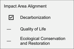
Energy and Atmosphere Credit
ENHANCED ENERGY EFFICIENCY
EAc2
1–12 points: 7 points are required for LEED Platinum projects.
INTENT
To design buildings that minimize energy use to reduce the environmental damage caused by resource extraction, air pollution, and GHG emissions, and to facilitate the transition to a clean energy future.
REQUIREMENTS
| Achievement pathways | Points |
|---|---|
Commercial Interiors | 1–12 |
Option 1. Prescriptive Path | 1–12 |
Path 1. ASHRAE 90.1-2022 Compliance for Project Scope | 3 |
AND/OR | |
Path 2. Regulated Loads | 1–4 |
Case 1. Additional Efficiency — Systems Optimization | 1–4 |
OR | |
Case 2. Additional Efficiency Requirements Beyond ASHRAE 90.1- 2022 | 1–4 |
OR | |
Path 3. Plug and Process Loads (PPL) | 1–5 |
Case 1. Plug Load Management | 1 |
AND/OR | |
Case 2. Efficient Plug and Process Load Equipment | 1–5 |
OR | |
Case 3. Plug and Process Load Exceptional Calculation | 1–5 |
Path 4. Base Building Energy Efficiency | 2 |
OR | |
Option 2. Energy Simulation | 1–12 |
Path 1. Percentage Reduction Excluding On-Site Renewable Contribution | 1–12 |
OR | |
Path 2. Percentage Reduction Including On-Site Renewable Contribution | 1–12 |
Option 1. Prescriptive Path (1–12 points)
PATH 1. ASHRAE 90.1-2022 COMPLIANCE FOR PROJECT SCOPE (3 POINTS)
Comply with the provisions of ASHRAE 90.1-2022, Sections 5–11 for the project scope of work.
AND/OR
U.S. Green Building Council LEED v5 Reference Guide for Interior Design and Construction, April 2025 Launch Edition 161
PDF Page 173
PATH 2. REGULATED LOADS (1–4 POINTS)
Apply Case 1 or Case 2, up to a maximum of 4 points:
Case 1. Additional Efficiency — Systems Optimization (1–4 points)
Points are awarded according to Table 1. For projects complying with Path 1, reference ASHRAE 90.1-2022 or approved equivalent standard. For other projects registered prior to January 1, 2028, reference ASHRAE 90.1-2019 or approved equivalent standard.
Table 1. Systems optimization
| Col1 | Threshold | Points |
|---|---|---|
| Lighting power. Reduce connected lighting power, including existing fixtures below the lighting power allowance by the specified percentage. | 15% | 1 |
| Lighting power. Reduce connected lighting power, including existing fixtures below the lighting power allowance by the specified percentage. | 30% | 2 |
Cooling, heating, and SWH efficiency. Demonstrate the specified percent improvement in prescriptive efficiencies for at least 75% of the combined cooling, heating, and SWH capacity installed or replaced in the project scope of work. | 15% | 1 |
Fan power. Demonstrate the specified percent improvement in fan power below the prescriptive fan power limitation for systems altered or replaced in the project scope of work. | 20% | 1 |
OR
Case 2. Additional Efficiency Requirements Beyond ASHRAE 90.1-2022 (1–4 points)
Applicable only to projects complying with ASHRAE 90.1-2022, Sections 5–11 that are also defined as “substantial alterations to existing buildings” per ASHRAE 90.1, Section 11.1.4. Points are awarded according to Table 2.
Document achievement of incremental ASHRAE 90.1-2022, Section 11 energy credits, above the minimum required by ASHRAE 90.1-2022, Section 11 from the following list of eligible measures:
Eligible measures from ASHRAE 90.1, Section 11.5.2, for LEED points
-
HVAC measures (H01 to H07)
-
SWH measures (W01 to W09)
-
Lighting measures (L01 to L06)
-
G07 Building Mass/Night Flush
Table 2. Points for ASHRAE 90.1-2022, Section 11 credits
| ASHRAE 90.1-2022, Section 11 credits | Points |
|---|---|
Minimum required by 90.1-2022 plus 13 credits | 1 |
| Minimum required by 90.1-2022 plus 25 credits | 2 |
U.S. Green Building Council LEED v5 Reference Guide for Interior Design and Construction, April 2025 Launch Edition 162
PDF Page 174
| ASHRAE 90.1-2022, Section 11 credits | Points |
|---|---|
Minimum required by 90.1-2022 plus 38 credits | 3 |
| Minimum required by 90.1-2022 plus 50 credits | 4 |
AND/OR
PATH 3. PLUG AND PROCESS LOADS (1–5 POINTS)
Case 1. Plug Load Management (1 point)
Implement the following:
-
Provide a plug load dashboard that is accessible through an application to all regular occupants of the space.
-
For tenant types with IT departments, implement policies for PCs, monitors, and visual displays to be controlled off when not in use, except scheduled maintenance periods.
AND/OR
Case 2. Efficient Plug and Process Load Equipment (1–5 points)
Implement one or more of the following:
-
Install or reuse eligible plug and process equipment meeting the criteria in Table 3 for 90% of applicable equipment by quantity or rated load. Either include or exclude all eligible equipment reused in the project from the calculations. For one Table 3 equipment category (1 point)
-
For two Table 3 equipment categories (2 points)
-
For three or more Table 3 equipment categories (3 points)
OR
For process-intensive spaces, install or reuse eligible plug and process equipment meeting the criteria in Table 3 for at least 90% of total applicable equipment rated load. Rated load of compliant equipment must total at least:
-
0.3 W/sq. ft. (3.2 W/sq. m.) (3 points)
-
0.5 W/sq. ft. (5.4 W/sq. m.) (4 points)
-
1.0 W/sq. ft. (10.8 W/sq. m.) (5 points)
Table 3. Plug, process, refrigeration, and conveyance equipment criteria
| Equipment category | Applicable equipment | Criteria |
|---|---|---|
ENERGY STAR® products: plug | Office equipment Appliances Electronics | ENERGY STAR® rated or approved equivalent with at |
U.S. Green Building Council LEED v5 Reference Guide for Interior Design and Construction, April 2025 Launch Edition 163
PDF Page 175
| Equipment category | Applicable equipment | Criteria |
|---|---|---|
loads and small appliances | Other (e.g., vending machines, pool pumps, water coolers) | least 0.1 W/sq. ft. (1.1 W/sq. m.) of total rated load |
| ENERGY STAR® products: process loads | Commercial food service equipment Data center/server equipment Commercial laundry equipment Electric vehicle chargers (EVSE) Other (e.g., laboratory-grade refrigerators and freezers) | ENERGY STAR® rated or approved equivalent with at least 0.1 W/sq. ft. (1.1 W/sq. m.) of total rated load |
| People conveyance | Elevators Escalators Moving walkways | ISO 25745 At least Class A-rated |
| Data center electrical system | Electrical system design | ASHRAE 90.4-2022 Design electrical loss component (ELC) is at least 20% lower than the maximum design electrical loss |
| Refrigeration systems | Referenced in_ASHRAE_ 90.1, Section 6.8, tables AND not ENERGY STAR®® eligible | 10% improvement beyond ASHRAE 90.1, Section 6.8, tables |
| Refrigeration systems | Refrigerated warehouse | California Title 24-2022, Section 120.6, refrigerated warehouse requirements |
| Airport equipment | Baggage handling equipment | Individual carrier systems (ICS) with variable frequency drive |
| Airport equipment | Aircraft and jetway air-conditioning | Preconditioned air (PCA) systems with efficiencies meeting_ASHRAE 90.1_ prescriptive efficiencies for HVAC equipment |
OR
Case 3. Plug and Process Load Exceptional Calculation (1–5 points)
Using the ASHRAE 90.1, Section G2.5, exceptional calculation method, demonstrate a minimum percentage improvement in total project plug and process, refrigeration, and conveyance loads. Points are awarded according to Table 4 below.
Table 4. Points for percent improvement in plug and process loads
| Percent improvement | Points |
|---|---|
| 8% | 1 |
16% | 2 |
24% | 3 |
32% | 4 |
40% | 5 |
U.S. Green Building Council LEED v5 Reference Guide for Interior Design and Construction, April 2025 Launch Edition 164
PDF Page 176
PATH 4. BASE BUILDING ENERGY EFFICIENCY (2 POINTS)
Locate in a base building that complies with one of the following:
-
ASHRAE 90.1-2022
-
Current ENERGY STAR® score of at least 75
-
LEED base building documentation of energy efficiency per Table 5
Table 5. LEED base building documentation of energy efficiency
| Interior fit-out classification | LEED Base Building Documentation of Energy Efficiency | Col3 | Col4 |
|---|---|---|---|
| Interior fit-out classification | Rating system(s) | EA credit name and credit option | Base building minimum threshold |
| Initial build-out | LEED v5 BD+C | EAc3: Enhanced Energy Efficiency | 5 points |
| Alterations of previously occupied space | LEED v5 O+M | EAc2: Optimized Energy Performance | 5 points |
Initial build-out | LEED v4 or LEED v4.1 BD+C | EAc2: Optimized Energy Performance | 8 points |
OR
Option 2. Energy Simulation (1–12 points)
Demonstrate an improvement in future source energy calculated per ASHRAE Standard 90.1, Normative Appendix G, “Performance Rating Method,” with the following additional provisions:
-
Use the ASHRAE 90.1 version applied for EAp2: Minimum Energy Efficiency .
-
Replace ASHRAE 90.1-2019 or 90.1-2022, Table 4.2.1.1, BPFs , with Table 7 below. For alterations except initial build-out construction, the following ASHRAE 90.1-2022 adjustments may be applied:
o Substantial alteration . Multiply the BPF by 1.05 if the alteration is defined as a
substantial alteration in ASHRAE 90.1-2022, Section G3.1.4(a).
o Other alterations . Apply ASHRAE 90.1-2022, Section G3.3 (“Performance
Calculations for Other Alterations”). For projects documented using ASHRAE 90.1-2019, Appendix G, replace all references to 90.1-2022, Section 5–10, prescriptive criteria with the corresponding 90.1-2019, Section 5–10 criteria.
-
Replace all references to “cost” with “future source energy.” Use an electric site-tosource energy conversion factor of 2.0 based on future projections for the U.S. A lower national average value may be used as applicable for projects outside of the U.S.
-
Model energy efficiency measures for plug and process loads using Section G2.5, “Exceptional Calculation Method,” or approved calculations in the LEED reference
U.S. Green Building Council LEED v5 Reference Guide for Interior Design and Construction, April 2025 Launch Edition 165
PDF Page 177
guidance. Calculate the PI and percentage improvement with and without the plug and process savings.
-
Calculate the PI and performance index target (PIt) as follows:
-
PInre = PBPnre / BBP
-
PI = PBP / BBP
-
PIt = [BBUE + (BPF x BBRE)] / BBP where :
-
o PInre = PI for future source energy excluding on-site renewable contribution
o PI = PI for future source energy including on-site renewable contribution
o PIt = performance index target for future source energy use
o BBP = baseline building performance for baseline building future source
energy use
o BBUE = baseline building unregulated future source energy use
o BBRE = baseline building regulated future source energy use
o PBPnre = proposed building performance without any credit for reduced
annual future source energy from on-site renewable energy generation systems
o PBP = proposed building performance, including the reduced annual future
source energy associated with all on-site renewable energy generation systems
Points are awarded according to Table 6, using either Path 1 or Path 2.
Table 6. Points for percentage improvement in PI below PIt
| Path 1. Percentage reduction excluding on-site renewable contribution (100%–PI / PI) nre t | OR | Path 2. Percentage reduction excluding on-site renewable contribution (100%–PI / PI) t | Points |
|---|---|---|---|
0% | 5% | 2 | |
2% | 2% | 10% | 3 |
4% | 4% | 20% | 4 |
6% | 6% | 30% | 5 |
8% | 8% | 40% | 6 |
10% | 10% | 50% | 7 |
12% | 12% | 60% | 8 |
14% | 14% | 70% | 9 |
16% | 16% | 80% | 10 |
18% | 18% | 90% | 11 |
20% | 20% | 100% | 12 |
U.S. Green Building Council LEED v5 Reference Guide for Interior Design and Construction, April 2025 Launch Edition 166
PDF Page 178
Table 7. ASHRAE 90.1-2019 — Equivalent BPFs for a future source energy metric
| Building type | Climate zone | Col3 | Col4 | Col5 | Col6 | Col7 | Col8 | Col9 | Col10 | Col11 | Col12 | Col13 | Col14 | Col15 | Col16 | Col17 | Col18 | Col19 | Col20 |
|---|---|---|---|---|---|---|---|---|---|---|---|---|---|---|---|---|---|---|---|
| **Building type ** | 0A | 0B | 1A | 1B | 2A | 2B | 3A | 3B | 3C | 4A | 4B | 4C | 5A | 5B | 5C | 6A | 6B | 7 | 8 |
| Multifamily | 0.74 | 0.69 | 0.73 | 0.70 | 0.73 | 0.70 | 0.71 | 0.70 | 0.63 | 0.70 | 0.71 | 0.69 | 0.68 | 0.70 | 0.70 | 0.68 | 0.68 | 0.68 | 0.74 |
Healthcare/hospital | 0.72 | 0.72 | 0.73 | 0.73 | 0.74 | 0.71 | 0.72 | 0.74 | 0.71 | 0.72 | 0.73 | 0.71 | 0.74 | 0.73 | 0.80 | 0.73 | 0.77 | 0.78 | 0.79 |
Hotel/motel | 0.72 | 0.71 | 0.72 | 0.71 | 0.71 | 0.70 | 0.71 | 0.73 | 0.72 | 0.71 | 0.73 | 0.73 | 0.71 | 0.73 | 0.74 | 0.70 | 0.72 | 0.70 | 0.70 |
Office | 0.62 | 0.63 | 0.61 | 0.62 | 0.58 | 0.60 | 0.57 | 0.62 | 0.55 | 0.55 | 0.61 | 0.57 | 0.58 | 0.61 | 0.59 | 0.58 | 0.60 | 0.54 | 0.58 |
Restaurant | 0.65 | 0.62 | 0.63 | 0.61 | 0.62 | 0.58 | 0.63 | 0.63 | 0.63 | 0.67 | 0.66 | 0.66 | 0.70 | 0.70 | 0.68 | 0.73 | 0.72 | 0.74 | 0.77 |
Retail | 0.57 | 0.54 | 0.53 | 0.53 | 0.48 | 0.47 | 0.47 | 0.47 | 0.47 | 0.52 | 0.50 | 0.56 | 0.57 | 0.53 | 0.59 | 0.58 | 0.56 | 0.53 | 0.60 |
School | 0.57 | 0.57 | 0.58 | 0.57 | 0.55 | 0.54 | 0.57 | 0.51 | 0.49 | 0.48 | 0.51 | 0.52 | 0.51 | 0.53 | 0.51 | 0.53 | 0.50 | 0.51 | 0.58 |
Warehouse | 0.28 | 0.30 | 0.24 | 0.27 | 0.23 | 0.24 | 0.27 | 0.23 | 0.20 | 0.33 | 0.26 | 0.28 | 0.40 | 0.32 | 0.29 | 0.44 | 0.38 | 0.40 | 0.44 |
All others | 0.65 | 0.62 | 0.64 | 0.62 | 0.57 | 0.54 | 0.57 | 0.56 | 0.58 | 0.59 | 0.57 | 0.60 | 0.60 | 0.59 | 0.65 | 0.62 | 0.62 | 0.61 | 0.64 |
REQUIREMENTS EXPLAINED
This credit rewards increased energy efficiency addressing regulated and unregulated systems in the project scope, and improved base building performance . To limit documentation level of effort, use the same ASHRAE 90.1 compliance method for prerequisite and credit compliance: either the prescriptive method or Appendix G PRM.
Table 8. Linked prerequisite and credit compliance options for energy efficiency
| EAp2: Minimum Energy Efficiency | Linked EAc2: Enhanced Energy Efficiency (choose Option 1 OR Option 2) | Available points |
|---|---|---|
| Option 1. ASHRAE 90.1-2019 Prescriptive method | Option 1. Prescriptive Path | 1–11 |
| Option 1. ASHRAE 90.1-2019 Prescriptive method | Path 2. Regulated Loads, Case 1. Additional efficiency systems optimization Reduce lighting power, increase HVAC and SWH equipment efficiency, and/or reduce fan power. | 1–4 |
| Option 1. ASHRAE 90.1-2019 Prescriptive method | AND/OR | + |
| Option 1. ASHRAE 90.1-2019 Prescriptive method | Path 3. Plug and process loads | 1–5 |
| Option 1. ASHRAE 90.1-2019 Prescriptive method | AND/OR | + |
| Option 1. ASHRAE 90.1-2019 Prescriptive method | Path 4. Base building energy efficiency | 2 |
| Option 2. ASHRAE 90.1-2022 Prescriptive method | Option 1. Prescriptive Path | 3–12 |
| Option 2. ASHRAE 90.1-2022 Prescriptive method | Path 1.ASHRAE 90.1-2022 compliance for project scope. Automatically achieved | 3 |
| Option 2. ASHRAE 90.1-2022 Prescriptive method | AND | + |
| Option 2. ASHRAE 90.1-2022 Prescriptive method | Path 2. Regulated loads | 4 |
| Option 2. ASHRAE 90.1-2022 Prescriptive method | Case 1. Additional efficiency systems optimization. Reduce lighting power, increase HVAC and SWH equipment efficiency, and/or reduce fan power. OR Case 2. Additional efficiency requirements beyond ASHRAE 90.1 2022 (Applicable to substantial alterations) | |
| Option 2. ASHRAE 90.1-2022 Prescriptive method | Case 1. Additional efficiency systems optimization. Reduce lighting power, increase HVAC and SWH equipment efficiency, and/or reduce fan power. OR Case 2. Additional efficiency requirements beyond ASHRAE 90.1 2022 (Applicable to substantial alterations) | + |
U.S. Green Building Council LEED v5 Reference Guide for Interior Design and Construction, April 2025 Launch Edition 167
PDF Page 179
| EAp2: Minimum Energy Efficiency | Linked EAc2: Enhanced Energy Efficiency (choose Option 1 OR Option 2) | Available points |
|---|---|---|
| Implement incremental efficiency measures for HVAC, SWH, lighting, and/or building mass with night flush per_ASHRAE_ 90.1-2022, Section 11. AND/OR | ||
Path 3. Plug and process loads | 1–5 | |
AND/OR | + | |
Path 4. Base building energy efficiency | 2 | |
| Option 1 or Option 2. 90.1-2019 or 90.1- 2022 ECB Method | Option 1. Prescriptive Path | 1–7 |
| Option 1 or Option 2. 90.1-2019 or 90.1- 2022 ECB Method | Path 3. Plug and process loads | 1–5 |
| Option 1 or Option 2. 90.1-2019 or 90.1- 2022 ECB Method | AND/OR | + |
| Option 1 or Option 2. 90.1-2019 or 90.1- 2022 ECB Method | Path 4. Base building energy efficiency | 2 |
Option 1 or Option 2. 90.1-2019 or 90.1- 2022 Appendix G — PRM | Option 2. Energy Simulation Implement efficiency measures to achieve a percentage reduction in “future source energy” below a performance Index Target (PIt). Initial build-out or substantial alteration. PIt referenced to_90.1- 2019 equivalent performance. Other alterations. PIt referenced to_ASHRAE 90.1 prescriptive requirements from referenced version of ASHRAE. | 1–12 |
Option 1. Prescriptive Path
Option 1 offers a streamlined approach to achieving energy efficiency without requiring complex energy modeling. Teams can combine paths under Option 1 to achieve up to 12 points for the credit. This option is particularly beneficial for projects with limited scope, or simple systems, or that or located in inefficient base buildings that detract from overall project performance documented using energy simulation.
The first three paths focus solely on efficiency implemented in the project scope. Path 1 rewards prescriptive method compliance with ASHRAE 90.1-2022 . Paths 2 and 3 reward improved efficiency for regulated loads and for plug and process loads respectively, with points weighted based on the typical distribution of regulated versus plug and process loads addressed in Interiors projects.
Path 4 recognizes energy efficiency in the base building.
PATH 1. ASHRAE 90.1-2022 COMPLIANCE FOR PROJECT SCOPE
Projects earn three points for complying with EAp2: Minimum Energy Efficiency, Option 2 . ASHRAE 90.1-2022 using the prescriptive method, regardless of whether project registration occurs after ASHRAE 90.1-2022 becomes obligatory January 1, 2028.
U.S. Green Building Council LEED v5 Reference Guide for Interior Design and Construction, April 2025 Launch Edition 168
PDF Page 180
For initial buildouts and substantial alterations, any ASHRAE 90.1-2022, Section 11.5.2 efficiency measures may be used to achieve the minimum energy credits required by ASHRAE 90.1-2022, Section 11 for the project’s type and climate zone. However, per ASHRAE 90.1- 2022 11.5.2, the combined contribution of renewable and load management measures is limited to 60% of the total required energy credits.
PATH 2. REGULATED LOADS
For projects that comply with EAp2: Minimum Energy Efficiency using the prescriptive method, Path 2 rewards further energy efficiency for the lighting, HVAC, and SWH systems installed in the project scope of work.
Case 1. Additional Efficiency — System Optimization
APPLICABILITY Case 1 primarily applies to projects documenting prerequisite compliance using ASHRAE 90.1-2019, Section 5–10 and to limited scope alterations of existing buildings complying with Path 1 above using ASHRAE 90.1-2022 .
Case 1 has limited applicability to substantial alterations and interior buildouts required to achieve energy credits by ASHRAE 90.1-2022, Section 11, because only strategies incremental to those used to achieve minimum required energy credits in ASHRAE 90.1, Section 11 may be used to show compliance:
o The lighting strategy cannot be used when measure L06: Reduce Interior Lighting
Power contributes toward minimum required energy credits ( ASHRAE 90.1-2022 11.5.2.5.6 ).
o The cooling, heating, and SWH efficiency strategy cannot be used when ASHRAE
90.1-2022, Section 11 measures H01, H02, H03, or W03 addressing HVAC and SWH equipment efficiency contribute toward minimum required energy credits.
o The fan power strategy cannot be used when measure H06: Dedicated Outdoor Air
System contributes toward minimum required energy credits ( ASHRAE 90.1-2022 11.5.2.2.6).
SYSTEM OPTIMIZATION STRATEGIES For projects pursuing Path 1. ASHRAE 90.1-2022 above, refer to the prescriptive requirements of ASHRAE 90.1-2022 for each strategy.
For other projects registered prior to January 1, 2028, refer to the prescriptive requirements from ASHRAE 90.1-2019 for each strategy.
Projects can combine multiple strategies to earn up to four points for all implemented strategies.
U.S. Green Building Council LEED v5 Reference Guide for Interior Design and Construction, April 2025 Launch Edition 169
PDF Page 181
Lighting Design efficient lighting that reduces connected lighting power by the specified percentage below the referenced version of ASHRAE Standard 90.1 .
Use either the building area method compliance path ( ASHRAE 90.1, Section 9.5) or the Spaceby-Space Method Compliance Path (Section 9.6) to calculate the lighting power allowance.
Include all new and existing interior lighting in the project boundary in the connected lighting power determination. For any existing or additional lighting power fixtures that are excluded from the ASHRAE 90.1 lighting power allowance calculated in Section 9.5 or 9.6, report this lighting power identically for the connected lighting power and for the adjusted ASHRAE 90.1 lighting power allowance used for this credit.
Cooling, heating, and SWH efficiency Install HVAC and SWH equipment that improves upon ASHRAE 90.1 minimum required efficiencies.
To confirm compliance, identify all equipment installed in the project scope that generates cooling, heating (including preheat and reheat), or SWH. Up to 25% of this capacity may be excluded for determination of credit compliance. Also exclude existing unmodified equipment or base building equipment supplying thermal energy to the space.
Calculate the percent improvement in equipment efficiency compared to the referenced version of ASHRAE 90.1 for each installed equipment. For heat pumps that have both heating and cooling efficiencies, use the capacities and efficiencies from both heating and cooling mode.
-
ASHRAE 90.1, Section 6.8 Tables for heating and cooling efficiencies
-
ASHRAE 90.1, Section 7.4 Tables for SWH
Efficiency improvement is 0% for electric resistance heating in baseboards, fan coils, VAV reheat, or air handling units.
Either achieve a 15% improvement for each individual equipment, totaling at least 75% of total installed capacity, or achieve a 15% weighted average efficiency improvement encompassing at least 75% of total installed capacity.
Equation 1. Weighted average % improvement
Equation 1. Weighted average % improvement 𝑊 𝑊 ℎ𝑡 𝑡 a𝑣 𝑣 𝑣 % 𝑖 𝑖 𝑖 𝑖 𝑖 𝑖 =
∑(𝑟 𝑟 𝑟 𝑐 𝑐 𝑐 𝑐 𝑜 𝑒 𝑒ℎ 𝑒 𝑒 𝑒 𝑒 𝑒 × % 𝑖 𝑖 𝑖 𝑖 𝑖 𝑖 𝑓 𝑓 𝑒 𝑒ℎ 𝑒 𝑒 𝑒 𝑒 𝑒)
(𝑡 𝑡 𝑡 𝑟 𝑟 𝑟 𝑒 𝑒 𝑒 𝑒 𝑒 𝑐 𝑐 𝑐 𝑐 𝑜 𝑎 𝑎 𝑒 𝑒 𝑒 𝑒 𝑒)
U.S. Green Building Council LEED v5 Reference Guide for Interior Design and Construction, April 2025 Launch Edition 170
PDF Page 182
Additional considerations Guidance for calculating weighted average efficiency improvement for heating or cooling equipment with multiple rated conditions is available in ASHRAE 90.1 2022, Sections 11.5.2.2.2 and 11.5.2.2.3, respectively.
Fan power The sum of all fan power installed within the project scope of work must be 20% less than the sum of total fan power allowed by ASHRAE 90.1 6.5.3.1.1 .
Eligibility for this credit requires the installation of at least one HVAC system with associated fans. Include all supply fans, return/relief fans, and fan-powered terminal units associated with the HVAC systems installed in scope. The project is ineligible to apply this strategy if for each HVAC system in scope, less than 50% of total system fan power is installed in scope.
For partial HVAC system installations (such as fan coils installed in the project scope with base building dedicated outside air), use the prorated fan power from the base building system to calculate the total percent improvement in system fan power for the associated HVAC system. Use only the fan power installed in scope to determine the overall percent improvement in fan power below the prescriptive limitation:
Equation 2. Fan power % improvement
Equation 2. Fan power % improvement 𝐹 𝐹 𝑝 𝑝 𝑝 % 𝑖 𝑖 𝑖 𝑖 𝑖 𝑖 =
∑(𝐹 𝐹 𝑝 𝑝 𝑝 𝑖 𝑠 𝑠 𝑠 𝑓 𝑓 𝑒 𝑒ℎ 𝐻 𝐻 𝑠 𝑠 𝑠 × % 𝑖 𝑖 𝑖 𝑖 𝑖 𝑖 𝑓 𝑓 𝑝 𝑝 𝑝 𝑓 𝑓 𝑒 𝑒ℎ 𝐻 𝐻 𝑠 𝑠 𝑠 )
(𝑡 𝑡 𝑡 𝑓 𝑓 𝑝 𝑝 𝑝 𝑖 𝑖 𝑖 𝑖 𝑖 𝑖 𝑝 𝑝 𝑝 𝑡 𝑠 𝑠 𝑠)
Additional considerations This strategy cannot be used when ASHRAE 90.1-2022 measures H01: HVAC System Performance Improvement (11.5.2.2.1) or H06: Reduce Interior Lighting Power (11.5.2.5.6) are used to document minimum required energy credits, since these are necessary for compliance with Path 1.
Case 2. Additional Efficiency Requirements Beyond ASHRAE 90.1-2022
APPLICABILITY Case 2 applies only to interior build-outs or substantial alterations that document compliance with ASHRAE 90.1-2022, Sections 5–10 and document a minimum number of required energy credits per ASHRAE 90.1-2022, Section 11.
For these project applications, Case 2 is more effective than Case 1 at distinguishing incremental energy improvements beyond the minimum level of performance required by ASHRAE 90.1-2022 .
U.S. Green Building Council LEED v5 Reference Guide for Interior Design and Construction, April 2025 Launch Edition 171
PDF Page 183
INCREMENTAL ENERGY CREDITS Projects must achieve incremental energy credits above the minimum required for prescriptive method compliance. These incremental energy credits must be from the list of eligible HVAC, lighting, SWH, or building mass/night flush measures rather than the full list of measures from ASHRAE 90.1-2022, Section 11.5.2. To assess achievement of incremental energy credits (ECinc):
o Identify the minimum energy credits required by ASHRAE 90.1-2022, Section 11
(ECreq).
- Determine the total combined energy credits achieved using ASHRAE 90.1- 2022, Section 11 from eligible measures and from noneligible measures (ECtotal).
o Determine the total combined energy credits achieved from the list of eligible
measures. (ECeligible).
o The quantity of incremental energy credits achieved is equal to the lesser of the
energy credits from eligible measures, or the total combined energy credits minus the energy credits required by ASHRAE 90.1-2022, Section 11.
inc eligible total req EC = Minimum (EC, EC - EC ) Example 1: Substantial alteration retail project in climate zone 4A All energy credits from eligible measures.
ASHRAE 90.1-2022, Section 11 requires 25 energy credits, determined by multiplying the 50% factor for substantial alterations referenced in ASHRAE 90.1, Section 11.5.1(c) by the 50 energy credits required for retail in climate zone 4A from ASHRAE 90.1-2022, Table 11.5.3-6 (ECreq = 25).
The project documents achievement of 52 total energy credits per ASHRAE 90.1-2022, Section 11, all of which are from measures eligible for LEED points.
-
H02: HVAC Heating Performance Improvement. 20% or greater weighted average improvement in ASHRAE 90.1-2022 heating efficiency achieves 28 energy credits.
-
L04: Increased Daylighting Control Area. 65% of total daylighting area with continuous daylight dimming achieves 4 energy credits.
-
L06: Reduce Interior Lighting Power. 10% or greater improvement in ASHRAE 90.1- 2022 regulated lighting power achieves 20 energy credits.
ECtotal = ECeligible = EC_H02 + EC_L04 + EC_L06
ECtotal = ECeligible = 28 + 4 + 20 = 52
U.S. Green Building Council LEED v5 Reference Guide for Interior Design and Construction, April 2025 Launch Edition 172
PDF Page 184
The project achieves 27 incremental energy credits above the minimum required for prescriptive method compliance, which exceeds the 25 required for two LEED points.
ECinc = Minimum (ECeligible, ECtotal − ECreq)
ECinc = Minimum (52, 52 − 25) = 27 Example 2. Substantial alteration retail project in climate zone 4A Renewable energy used to earn energy credits for prerequisite compliance.
The project referenced in Example 1 adds a roof-mounted PV array with a rated capacity of at least 0.75 W/sq. feet (8.1 W/sq. m.) of the project’s gross floor area, achieving 15 energy credits for measure R01: On-site Renewable Energy, and maximizing the combined allowable ASHRAE 90.1-2022, Section 11 contribution for renewable and load management credits. The project achieves 67 total energy credits per ASHRAE 90.1-2022, Section 11.
ECtotal = EC_H02 + EC_L04 + EC_L06 + EC_R01
ECtotal = 28 + 4 + 20 + 15 = 67 Of these energy credits, 52 are from measures eligible for LEED points (H02, L04, and L06). Therefore, the project achieves 42 incremental energy credits above the minimum required for prescriptive method compliance, which exceeds the 38 required for three LEED points.
ECinc = Minimum ( ECeligible, ECtotal - ECreq )
ECeligible = Minimum ( 52, 67 - 25 ) = 42
ELIGIBLE MEASURES FOR PATH 1. REGULATED LOADS Table 1. Eligible measures from ASHRAE 90.1-2022 Section 11.5.2 for LEED points
| HVAC Measures | Lighting Measures |
|---|---|
H01: HVAC System Performance Improvement (ASHRAE 90.1-2022, Addendum J)* | L01. Lighting System Performance** |
H02: HVAC Heating Performance Improvement. | L02: Lighting Dimming and Tuning. |
H03: HVAC Cooling Performance Improvement. | L03: Increase Occupancy Sensor. |
H04: Residential HVAC Controls. | L04: Increase Daylight Area. |
H05: Ground-Source Heat Pump. | L05: Residential Light Controls. |
H06: DOAS/Fan Controls. H07: Guideline 36 Sequences. | L06: Light Power Reduction. |
SWH Measures | Load Management Measures |
| W01: SHW Preheat Recovery. | G07: Building Mass/Night Flush. |
W02: Heat-Pump Water Heater. | W02: Heat-Pump Water Heater. |
W03: Efficient Gas Water Heater. | W03: Efficient Gas Water Heater. |
W04: SWH Pipe Insulation. | W04: SWH Pipe Insulation. |
W05: Point-of-Use Water Heaters. | W05: Point-of-Use Water Heaters. |
U.S. Green Building Council LEED v5 Reference Guide for Interior Design and Construction, April 2025 Launch Edition 173
PDF Page 185
| HVAC Measures | Lighting Measures |
|---|---|
W06: Thermostatic Balancing Valves. | |
W07: SHW Submeters. | W07: SHW Submeters. |
W08: SHW Distribution Sizing. | W08: SHW Distribution Sizing. |
W09: Shower Drain Heat Recovery. | W09: Shower Drain Heat Recovery. |
*Cannot be used in conjunction with H02, H03, or H06
*Not included in ASHRAE 90.1-2022 but may be in future ASHRAE addenda
The remaining measures referenced in ASHRAE 90.1-2022, Section 11.5.2 are ineligible for incremental LEED points, since these measures are separately rewarded in other LEED credits:
-
P01: Energy Monitoring is rewarded under EAc4: Enhanced Commissioning, Option 2. Monitoring-Based Commissioning (MBCx)
-
R01: Renewable Energy rewarded in EAc3: Renewable Energy
-
Q01: Efficient Elevator Equipment and Q02: Efficient Kitchen Equipment rewarded in EAc2: Enhanced Energy Efficiency, Option 1, Path 3. Plug and Process Loads.
-
G01 to G06 Load Management and E01: Improved Envelope Performance measures rewarded in EAc5: Grid Interactive
EQUIVALENCE TO ASHRAE 90.1 FOR OPTION 1. PRESCRIPTIVE PATH, PATHS 1 AND 2.
Refer to the Project Priorities Library for regional paths addressing equivalence to ASHRAE 90.1 .
To be eligible to apply Paths 1 or 2 of EAc2: Enhanced Energy Efficiency, Option 1. Prescriptive Path, projects using an ASHRAE 90.1 equivalent standard must use a prescriptive method from that standard: compliance must be demonstrated per category of building systems (building envelope, HVAC, lighting, SWH, etc.), without trade-offs between system categories.
Path 1. ASHRAE 90.1-2022 Compliance for Project Scope
This path is awarded to projects documented using a prescriptive method of an ASHRAE 90.1- 2022 equivalent standard.
Path 2. Regulated Loads
CASE 1. ADDITIONAL EFFICIENCY — SYSTEMS OPTIMIZATION APPLIES TO MOST PROJECTS USING AN EQUIVALENT STANDARD Prescriptive values from the ASHRAE 90.1-2019 -equivalent standard for efficiencies such as lighting power density allowance or equipment efficiency may replace ASHRAE 90.1-2022, Section 11 referenced values. Any strategies applied must be incremental to
U.S. Green Building Council LEED v5 Reference Guide for Interior Design and Construction, April 2025 Launch Edition 174
PDF Page 186
the minimum prescriptive requirements documented for the standard, including any additional efficiency measures required by the standard.
CASE 2. ADDITIONAL EFFICIENCY — REQUIREMENTS BEYOND ASHRAE 90.1- 2022 This may only be applied to interior buildouts documented using International Energy Conservation Code 2024 (IECC-2024) when Section C406 requires these projects to achieve a minimum number of energy credits. To use Case 2, directly replace energy credits from ASHRAE 90.1-2022, Section 11, Additional Efficiency Requirements with C406 energy credits . Implement incremental C406 energy credits, above the minimum required in Section C406 from the list of eligible measures:
o HVAC (H01 to H05)
o Lighting (L01 to L06)
o SWH (W01 to W10)
PATH 3. PLUG AND PROCESS LOADS
Path 3 places a spotlight on plug, process, cooking, refrigeration, and elevator/escalator system energy use that represent 30% - 50% of building energy usage yet are only partially or peripherally addressed through ASHRAE 90.1 standard requirements.
Projects may apply Case 1 in conjunction with Case 2 or document compliance with Case 1, Case 2, or Case 3 independently.
Case 1. Plug Load Management
A plug load dashboard empowers occupants to actively engage in reducing project energy consumption from plug loads. To comply with the credit requirements, the dashboard must be accessible to all regular occupants of the space and summarize project receptacle use, at least monthly. For projects with required monitoring and recording of receptacle use at 15-minute intervals per EAp4: Energy Metering and Reporting, use the dashboard to visualize this data, and compare receptacle energy consumption to the prior interval annually, monthly, daily, and hourly. The dashboard is only required to show usage for receptacle circuits but may optionally address other process usage (such as elevators), or other project end uses (such as lighting or HVAC energy).
If the operator of the space has an IT department that oversees computing operations in the space, policies must be employed to control equipment off or in a very low power mode when not in use, except during scheduled maintenance periods. The policy must address monitors, visual displays, personal computers, and laptops.
U.S. Green Building Council LEED v5 Reference Guide for Interior Design and Construction, April 2025 Launch Edition 175
PDF Page 187
Case 2 Efficient Plug and Process Load Equipment
Case 2 provides a streamlined path for rewarding plug and process equipment efficiency. The path is best suited for projects where a significant proportion of the project’s plug and process load consists of equipment referenced in Table 3 of the rating system.
One point is rewarded for each equipment category where at least 90% of applicable project equipment in the project scope meets the efficiency criteria, up to a maximum of three points. Ninety percent of applicable equipment may be assessed using either equipment quantity or rated load:
-
Equipment quantity . Divide the total quantity of equipment that meets the efficiency criteria for the equipment category by the total quantity of applicable equipment within the project scope for the equipment category.
-
Rated load . For applicable equipment in the equipment category, divide the sum of rated load for equipment that meets the efficiency criteria by the sum of rated load for all equipment within the project scope.
Either include or exclude all applicable equipment reused in the project from the calculations. Reused ENERGY STAR® products are deemed compliant even when not meeting current ENERGY STAR® specifications.
To ensure a measurable impact on project performance, Table 3 criteria for both ENERGY STAR® products categories stipulate a minimum 0.1 W/sq. ft. (1.1 W/sq. m.) of eligible equipment per unit of gross floor area. When the project has less than 0.1 W/sq. ft. (1.1 W/sq. m.) of rated load for each individual ENERGY STAR® Products Equipment Category but exceeds this value for the sum of the two categories, credit will be rewarded as one consolidated Table 3 equipment category.
Process-intensive spaces Process-intensive spaces such as data centers, restaurants, or refrigerated warehouses have greater potential to achieve substantial project energy savings from a single equipment category. Therefore, projects with combined equipment load from the equipment categories in Table 3 totaling at least 0.3 W/sq. ft. (3.2 W/sq. m.) of gross floor area may assess compliance based on 90% of total applicable equipment rated load rather than per equipment category. All applicable equipment from all Table 3 equipment categories must be included in the assessment of credit compliance.
Equivalence to ENERGY STAR® products Refer to the Project Priorities Library for regional paths addressing equivalence to ENERGY STAR® products.
U.S. Green Building Council LEED v5 Reference Guide for Interior Design and Construction, April 2025 Launch Edition 176
PDF Page 188
Case 3 Plug and Process Load Exceptional Calculation
Case 3 primarily applies to project applications with unique plug and process loads largely unaddressed by Table 3 equipment categories (such as manufacturing or laboratory) or projects where the streamlined methodology from Case 1 and 2 insufficiently reveals magnitude of impact for plug and process efficiency measures implemented for the project. Case 3 cannot be combined with Case 1 or Case 2.
Project analysts must use the ASHRAE 90.1, Section G2.5 exceptional calculation method to demonstrate a minimum percentage improvement in total plug and process energy usage compared to a baseline representative of standard practice for a similar project. Perform a detailed assessment to determine the total estimated annual energy consumption from all new and existing plug and process equipment in the project space, even when regulated under ASHRAE 90.1 :
-
Receptacle equipment
-
Cooking equipment
-
Refrigeration equipment
-
Conveyance equipment including elevators, escalators, or moving walkways
-
Process heating or process cooling (e.g., for manufacturing processes)
-
Data center IT equipment and Electrical Loss Component
-
All other process energy used to support a manufacturing, industrial, or commercial activity other than conditioning spaces and maintaining comfort and amenities for the occupants of a building
For each process efficiency measure implemented in the project, document that the efficiency measure is not conventional practice. Examples include:
-
A recent study with researched tabulations or monitored data establishing standard practice for the given application in similar newly constructed facilities
-
A new-construction utility or government program that provides incentives for the measure
-
A document showing the systems used to perform an analogous function in similar facilities built or reconstructed within the past 10 years
-
Applicable prescriptive requirements from the version of ASHRAE 90.1 or equivalent standard used for EAp2: Minimum Energy Efficiency
Use the conventional practice references to define the baseline systems. Provide detailed calculations and supporting narrative justification for any variations in baseline and proposed energy use.
U.S. Green Building Council LEED v5 Reference Guide for Interior Design and Construction, April 2025 Launch Edition 177
PDF Page 189
PATH 4. BASE BUILDING ENERGY EFFICIENCY
When developers and owners are identifying leasing opportunities for their fit-out, targeting high-performing buildings will allow the tenant fit-outs to optimize their energy performance.
ASHRAE 90.1 or ENERGY STAR® For projects that are in a building that meets ASHRAE 90.1-2022, or for buildings that achieve an ENERGY STAR® score of at least 75, two points can be earned under this path.
Previously LEED-certified base building For projects located in a previously LEED-certified base building, coordinate with the building owner or facility manager to gather information about the rating system, the version of the rating system, the level of certification, and the number of points achieved for the respective Energy Efficiency credits. Points are awarded according to Table 5.
Option 2. Energy Simulation
Option 2 rewards future source energy improvement below a Performance Index Target (PIt) documented per ASHRAE 90.1, Appendix G PRM. The credit structure prioritizes efficiency over on-site renewable energy, setting the performance improvement thresholds five times higher for Path 2 (including on-site renewable contribution) than for Path 1 (excluding on-site renewable contribution).
Assessment of credit compliance often requires simple additional calculations applied to the outputs from the ASHRAE 90.1, Appendix G PRM energy models used to document EAp2: Minimum Energy Efficiency, adjusting the metric, treatment of renewable energy, and/or BPF .
-
Future source energy . The future source energy metric must be used to assess credit compliance even when a different metric is used to document prerequisite compliance.
-
BPF . For substantial alterations or initial build-outs, Performance Index Target (PIt) must be calculated using LEED-published BPFs derived for the future source energy metric.
-
Treatment of on-site renewable energy .
o The on-site renewable energy contribution must either be fully excluded for Path 1 or
fully included for Path 2.
o The Performance Index Target (PIt) includes no adjustments for renewable energy,
unlike ASHRAE 90.1-2022 which adjusts for prescriptively required on-site renewable energy.
Further energy savings may also be documented for plug and process and/or district energy efficiency measures that do not contribute toward prerequisite compliance.
U.S. Green Building Council LEED v5 Reference Guide for Interior Design and Construction, April 2025 Launch Edition 178
PDF Page 190
FUTURE SOURCE ENERGY METRIC
All projects must use the future source energy metric for credit compliance. This metric reflects the average environmental impact of project energy consumption through 2050, considering the primary energy sources and their associated emissions.
Future Source Energy Conversion Factor (Primary Energy Factor — PEF)
The terms “source energy” and “source energy conversion factor” referenced below may be used interchangeably with the corresponding terms “primary energy” and PEF commonly used in the European Union.
Source energy is defined as the site energy plus the estimated energy consumed or lost in the extraction, processing, and transportation of primary energy forms such as coal, oil, natural gas, biomass, and nuclear fuel; energy consumed in conversion to electricity or thermal energy; and energy consumed or lost in transmission and distribution to the building site.
Source energy conversion factors must be at least one for all electricity and combustible fuel sources.
Electricity Future source energy is determined using a national average electric site-to-source conversion factor rather than a more granular determination by grid region or province to enable broader comparison of project energy efficiency across the entire spectrum of projects, and to account for the interconnectedness of electric grids.
-
For projects located in the U.S., use a national average electricity source energy conversion factor of 2.0 based on projections through 2050.
-
Projects located in other countries must use this same source energy conversion factor of 2.0 or provide data supporting a lower average source energy conversion factor for the project’s country. EU-average values may be used instead of the national average for projects in the European Union. The source energy conversion factor must be one of the following:
o Current published national- or EU-average source energy conversion factor.
o National- or EU-average source energy conversion factor from the present through
2050 or earlier, determined based on published, policy-based grid renewable projections. This can be calculated by averaging the current published national or EU-average source energy conversion factor and the predicted source energy conversion factor for the year 2050 or earlier; or by an average that accounts for year-to-year source energy projections.
U.S. Green Building Council LEED v5 Reference Guide for Interior Design and Construction, April 2025 Launch Edition 179
PDF Page 191
For example, projects in Europe may use the current default factor from the EU directive (1.9 as of this publication [43] ), a lower published factor from the project’s EU member state, or a factor determined based on policy-based published grid renewable projections through 2050 for the EU or the project’s member state.
More granular future source energy conversion factors per state, province, or eGRID region are not allowed because these necessitate greater complexity of EAc2: Enhanced Energy Efficiency requirements and increase ambiguity in comparative results.
Fuel Use one of the following references for conversion factors:
ENERGY STAR® Portfolio Manager Technical Reference: Source Energy [44] Natural gas source energy conversion factor = 1.09 per ASHRAE 90.1-2022, Table I5-1.
-
ASHRAE 100-2024 [45] Table 5-2 or ASHRAE 228 [46] Table 4.
-
Published national or EU-average source energy conversion factor conforming to the definition of source energy provided above.
District energy systems (DES) For projects that directly model purchased heat and/or purchased CHW as independent sources, refer to EAp2: Minimum Energy Efficiency, DES, Method B.
Source energy factors published by the DES provider or calculated for a campus DES system must conform to the definition of source energy provided above.
Future Source Energy Only Acceptable Metric for EAc2: Enhanced Energy Efficiency
The future source energy metric prioritizes energy efficiency, limiting “trade-offs” with decarbonization measures recognized in other LEED credits. Other metrics used for code compliance or EAp2: Minimum Energy Efficiency are not applicable for EAc2: Enhanced Energy Efficiency:
43 “Directive (EU) 2023/1791 of the European Parliament and of the Council of 13 September 2023 on energy efficiency and amending Regulation (EU) 2023/955”, European Parliament, Council of the European Union, June 13, 2024, https://eur[lex.europa.eu/eli/dir/2023/1791/.](https://eur-lex.europa.eu/eli/dir/2023/1791/) 44 “ENERGY STAR® Portfolio Manager Technical Reference: Source Energy”, ENERGY STAR®, accessed March 31, 2025, https://www.energystar.gov/buildings/tools-and-resources/portfolio-manager-technical-reference-source-energy. 45 “ASHRAE 100-2024”, ASHRAE, accessed March 31, 2025, https://webstore.ansi.org/standards/ashrae/ansiashraeiesstandard1002024?srsltid=AfmBOoooV3zeh4CHWn8HWU7alLQbx6KJcwyN28B1uQaa-fa4tdweiwc. 46 “ASHRAE 228”, ASHRAE, accessed March 31, 2025, https://store.accuristech.com/ashrae/standards/ashrae-2282023?product_id=2562375.
U.S. Green Building Council LEED v5 Reference Guide for Interior Design and Construction, April 2025 Launch Edition 180
PDF Page 192
-
Energy costs can fluctuate due to market conditions, subsidies, and other economic factors, skewing the representation of the environmental footprint of energy use for the cost metric.
-
A site energy metric overemphasizes the decarbonization already credited under EAc1: Electrification .
- A GHG emissions metric overemphasizes the decarbonization already credited under EAc1: Electrification and EAc3: Renewable Energy .
Building Performance Factor (BPF) For substantial alterations and initial buildouts, Performance Index Target (PIt) must be calculated using LEED-published BPFs from the rating system Table 7, which are derived for a future source energy metric based on ASHRAE 90.1-2019 equivalent performance. For projects that document prerequisite compliance using ASHRAE 90.1-2022, this directly rewards the differential future source energy savings from ASHRAE 90.1-2019 to ASHRAE 90.1-2022 .
For substantial alterations, multiply the LEED-published BPFs by 1.05 for the proportion of existing project area associated with each building area type.
BPFs are not used for other alterations of existing buildings. Refer to the EAp2: Minimum Energy Efficiency guidance for further context.
Treatment of on-site renewable energy (Option 2. Energy Simulation) The Performance Index Target (PIt) for EAc2: Enhanced Energy Efficiency omits the ASHRAE 90.1-2022 4.2.1.1 “PRE” adjustment for prescriptively required on-site renewable energy, matching the ASHRAE 90.1-2019 equation for PIt:
× t PI = [BBUE + (BPF BBRE)] / BBP
To determine the PI, either fully exclude the renewable contribution for Path 1, or fully include the renewable contribution for Path 2.
PATH 1. PERCENTAGE REDUCTION EXCLUDING ON-SITE RENEWABLE CONTRIBUTION
Path 1, the default energy simulation path, focuses solely on energy efficiency, requiring energy savings at or near achievable technical potential for maximum achievement of points.
This path does not recognize any on-site renewable contribution for the project (striking out ASHRAE 90.1 G2.4, on-site renewable energy guidance). Calculate the PBP with total proposed design energy for all electricity, fuel, and district energy use, regardless of whether this energy is purchased or generated from on-site renewable systems.
U.S. Green Building Council LEED v5 Reference Guide for Interior Design and Construction, April 2025 Launch Edition 181
PDF Page 193
PATH 2. PERCENTAGE REDUCTION INCLUDING ON-SITE RENEWABLE CONTRIBUTION
Path 2 applies primarily to project types that have limited opportunities for incremental energy savings beyond the referenced standard, such as unconditioned warehouses, and to projects that generate a large proportion of total project energy from on-site renewables.
Consistent with ASHRAE 90.1 G2.4, this path credits the on-site renewable contribution for the project. Prior to calculating the PBP, subtract eligible on-site renewable energy generation from the proposed design energy consumption. Total savings documented for on-site renewable electricity generation can be up to 100% of project electricity use on an annual basis. To qualify for credit compliance, the on-site renewable energy must be installed and commissioned within the project scope of work, or an earlier scope of work on the base building or the site of a contiguous campus, with all renewable attributes allocated to the project.
Plug and process efficiency For EAc2: Enhanced Energy Efficiency, projects may document credit for plug and process efficiency using ASHRAE 90.1 G2.5, Exceptional Calculation Method .
Document that each process efficiency measure is not conventional practice and provide detailed calculations and narrative justification supporting the future source energy savings claimed. (See additional guidance from Option 1, Path 3, Case 3 Plug and Process Load Exceptional Calculation). To convey the magnitude of impact associated with process efficiency measures, the energy analyst must separately report the PI, Performance Index Target, and all associated terms with and without the process efficiency savings.
District energy For EAc2: Enhanced Energy Efficiency, energy analysts may optionally replace prescriptive purchased heat and purchased CHW efficiencies modeled per ASHRAE 90.1-2022, Addendum A with improved virtual DES efficiencies representative of the DES purchase heat and purchased CHW systems serving the project.
Provide an engineering analysis based on monitored data and/or energy simulation to justify the improved virtual DES efficiencies modeled for the project. For each DES source, virtual DES efficiency must account for total annual energy required to generate and distribute the district energy. Include all pump energy use from the DES and within the project, thermal distribution losses, heat rejection, and all operational effects influencing efficiency such as standby losses, equipment cycling, equipment staging, and partial-load operation. When thermal distribution losses are not measured or modeled, estimate default losses of 5% for CHW, 10% for hot water, 15% for closed-loop steam, and 25% for open-loop steam.
U.S. Green Building Council LEED v5 Reference Guide for Interior Design and Construction, April 2025 Launch Edition 182
PDF Page 194
No further adjustments are required to a BBP model with purchased heat and purchased CHW documented per ASHRAE 90.1-2022, Addendum A in EAp2: Minimum Energy Efficiency .
Combined heat and power (CHP) To limit undue credit for site-recovered energy from CHP with on-site combustion emissions, projects must model CHP systems using one of the following methods instead of ASHRAE 90.1 G2.4.2.1:
-
CHP in baseline and proposed . Model CHP systems including all fuel inputs and associated site-recovered energy identically in the baseline design and the proposed design.
-
Purchased electricity in baseline and proposed . Model purchased electricity instead of the on-site electricity generation. Either credit site-recovered energy from the CHP toward the thermal loads for the baseline and proposed design identically; or ignore the site-recovered energy contribution in the baseline and proposed design).
-
CHP in proposed and purchased electricity in baseline . Model CHP systems including all fuel inputs and associated site-recovered energy in the proposed design. Model the baseline design per ASHRAE 90.1 with purchased electricity and with no credit for site-recovered energy.
DOCUMENTATION
| Project types All | Options All | Paths All | Documentation Demonstrate compliance with EAp2: Minimum |
|---|---|---|---|
All | All | All | Demonstrate compliance with_EAp2: Minimum_ Energy Efficiency. |
All | Option 1 | Path 1 | Demonstrate compliance with_EAp2: Minimum_ Energy Efficiency ASHRAE 90.1-2022, Sections 5– 11. |
All | Option 1 | Path 2: Case 1 | Upload calculator to demonstrate compliance. |
All | Option 1 | Path 2: Case 2 | Upload calculator to demonstrate compliance. |
All | Option 1 | Path 3: Case 1 | Demonstrate compliance that plug load dashboard has been supplied and meets requirements. Examples include screenshots of dashboard, photos, specifications etc. |
All | Option 1 | Path 3: Case 1 | Provide documentation and/or IT policy. |
All | Option 1 | Path 3: Case 2 | Provide documentation installed equipment meets criteria in Table 3 |
All | Option 1 | Path 3: Case 3 | Upload plug and process load exceptional calculation and associated documentation. |
All | Option 1 | Path 4 | ENERGY STAR® certificate; Comcheck or other approved method showing compliance with_ASHRAE_ 90.1 2022 or LEED credits. |
U.S. Green Building Council LEED v5 Reference Guide for Interior Design and Construction, April 2025 Launch Edition 183
PDF Page 195
| Project types | Options | Paths Performance | Documentation Demonstrate compliance with EAp2: Minimum |
|---|---|---|---|
| Performance Path | Demonstrate compliance with_EAp2: Minimum_ Energy Efficiency. | ||
| Option 2 | Path 1 | Demonstrate improvement in future source energy calculated per_ASHRAE_ Standard 90.1, Normative Appendix G “Performance Rating Method” with noted provisions [On-site RE excluded]. | |
| Option 2 | Path 2 | Demonstrate improvement in future source energy calculated per_ASHRAE_ Standard 90.1, Normative Appendix G “Performance Rating Method” with noted provisions [On-site RE included]. |
REFERENCED STANDARDS
-
ASHRAE 90.1-2019 (store.accuristech.com/ashrae/standards/ashrae-90-1-2019-i- p?product_id=2088527)
-
ASHRAE 90.1-2022 (store.accuristech.com/ashrae/standards/ashrae-90-1-2022-i- p?product_id=2522082)
-
ASHRAE 100-2024 (ashrae.org/technical-resources/bookstore/standard-100)
U.S. Green Building Council LEED v5 Reference Guide for Interior Design and Construction, April 2025 Launch Edition 184
PDF Page 196
Energy and Atmosphere Credit
RENEWABLE ENERGY
EAc3
1–5 points: 100% of tenant annual site energy consumption from any combination of Tier 1, Tier 2, and Tier 3 renewable energy is required for LEED Platinum projects.
INTENT
To encourage and recognize the use of renewable energy to reduce environmental and economic impacts associated with fossil fuel energy use and increase the supply of new renewable energy within the electrical grid, fostering a just transition to a green economy.
REQUIREMENTS
| Achievement pathways | Points |
|---|---|
Commercial Interiors | 1–5 |
Renewable Energy Supply or Procurement | 1–5 |
Supply or procure renewable energy meeting the renewable energy criteria referenced below. Points are rewarded according to Table 1.
Points documented for Tier 1, Tier 2, and/or Tier 3 renewable energy may be added together up to a maximum of 5 points.
Tenant annual site energy consumption must include the total estimated annual electricity and fuel use for systems and equipment within the project boundary or exclusively serving the project space (excludes shared air handling units or thermal energy).
AND
The total estimated annual energy consumption for thermal energy (CHW or hot water) supplied directly to the tenant by a utility, energy provider, or plant that is not in the building.
Renewable energy may be allocated to the tenant from the base building, provided it is allocated equally for the entire building area (including tenant area and base building core area)
OR
Incremental to the renewable energy required for the base building for LEED Core and Shell EAc4: Renewable Energy .
U.S. Green Building Council LEED v5 Reference Guide for Interior Design and Construction, April 2025 Launch Edition 185
PDF Page 197
Table 1. Points for renewable energy procurement
| Points | Tier 1 | Col3 | Col4 | Tier 2 | Tier 3 |
|---|---|---|---|---|---|
| Points | Minimum rated capacity1 | OR | Percent of tenant annual site energy | Percent of tenant annual site energy | Percent of tenant annual site energy |
| 1 | A* 1 W / sq. ft. (A * 10.8 W/sq. m.) | OR | 5% | 20% | 50% |
| 2 | A* 2 W / sq. ft. (A* 21.6 W/sq. m.) | OR | 10% | 40% | 100% |
| 3 | 20% | 60% | |||
4 | 35% | 80% | |||
5 | 100% Tier 1 and/or Tier 2 renewable energy | 100% Tier 1 and/or Tier 2 renewable energy |
*A = the sum of gross floor area of all floors of the building up to the three largest floors of the building, prorated to the project based on project area.
Renewable Energy Criteria
RENEWABLE ENERGY CLASSIFICATIONS
Tier 1. On-site Renewable Energy Generation or Social Impact Project
The renewable generation equipment may be located:
-
On the project site.
-
On the campus on which a project is located.
-
On the site of an equity project, as long as the renewable power system is provided, installed, and commissioned at no cost to the equity entity; that the ownership of the renewable power system is transferred to the equity entity; and that the rights to the power provided be given to the equity entity.
Tier 2. New Off-site Renewable Electricity
Off-site renewable electricity produced by new generation asset(s) must be:
-
Contracted to be operational within two years of building occupancy, OR
-
Contracted no more than five years after the renewable asset’s commercial operations date
Tier 3. Off-site Renewable Energy
-
Off-site renewable electricity that is Green-e® Energy certified or equivalent
-
Renewable fuels that are Green-e® Energy certified or equivalent
U.S. Green Building Council LEED v5 Reference Guide for Interior Design and Construction, April 2025 Launch Edition 186
PDF Page 198
CONTRACT LENGTH
- Contract length shall be 10 years or prorated across 10 years for shorter contract lengths.
ENVIRONMENTAL ATTRIBUTES
-
Ownership : All environmental attributes (energy attribute certificates, EACs) or renewable energy certificates, RECs) associated with renewable energy generation must be retired on behalf of the LEED project for the renewable energy procurement to contribute to credit achievement.
-
Project energy source : Renewable electricity generation and EAC procurement can only be applied to tenant electricity use or district energy use up to 100% of annual electricity plus district energy use. Renewable fuels can only be applied to tenant fuel use or district heat up to 100% of annual fuel plus district heat use.
-
Vintage : EACs credited to the project must be generated no earlier than 18 months before the LEED project’s initial application submission date.
-
Location : Tier 2 and Tier 3 renewable assets must be in the same country or region where the LEED project is located.
-
Tier 2 bulk purchase : Green-e® Energy certification or equivalent is required for onetime purchase or annual purchase of EACs or renewable power totaling more than 100% of the tenant’s annual electricity use.
REQUIREMENTS EXPLAINED
The credit establishes a three-tier hierarchy for renewable energy, preferentially rewarding renewable energy supply and procurement that has the most direct and long-term impacts on building decarbonization:
-
Tier 1 . On-site renewable energy generation or social impact project
-
Tier 2 . New off-site renewable electricity
-
Tier 3 . Off-site renewable energy
Projects may choose to supply or procure renewable energy from Tier 1, Tier 2, and/or Tier 3 for a maximum of five points.
For all three tiers of renewable energy, the project team should first confirm that the project will comply with the credit requirements for renewable energy environmental attributes and renewable contract length before proceeding with procurement and/or installation of the renewable energy.
U.S. Green Building Council LEED v5 Reference Guide for Interior Design and Construction, April 2025 Launch Edition 187
PDF Page 199
Tenant Annual Site Energy Determination
For Tier 1, Tier 2, and Tier 3 percent of tenant annual site energy
Tenant annual site energy includes all electricity and fuel used within the project boundary, all electricity and fuel for systems exclusively serving the project space, and all district energy supplied from outside of the project boundary directly to the project space.
Include all project lighting and plug and process energy use.
-
Include all electricity and fuel use for HVAC and SWH systems that are wholly contained in the project boundary or exclusively serve the project space. Examples include packaged single zone rooftop systems, water source heat pumps, VRF systems, water heaters, and floor-by-floor VAV air handling units dedicated for project use.
-
Include all electricity use for components of shared HVAC systems within the project boundary, such as VAV terminal units or fan coil units.
Tenant annual site energy does not include common area use or base building energy consumption from shared systems serving tenants, such as chiller plants, boiler plants, central water heating, shared VAV air handling units, or dedicated outside air handling units.
For projects that meter their electricity and fuel use, tenant annual site energy use aligns with this usage, supporting procurement of Tier 2 or Tier 3 renewable energy through a utility green tariff.
Exclusion of energy for electric vehicle charging Exclude energy for electric vehicle charging of vehicles used for off-site transportation purposes.
Renewable energy procurement may be contractually linked to a percentage of monthly metered data for each project energy source, summing together to the renewable percent of tenant annual site energy claimed for the project, or tenant annual site energy may be estimated for the project.
ENERGY SIMULATION
Projects using energy modeling to demonstrate compliance with EAp2: Minimum Energy Efficiency must use the PBP without renewable contribution as the basis for tenant annual site energy.
- For projects referencing the ASHRAE 90.1, Appendix G PRM, begin with the site energy consumption for the PBP without any credit for the on-site renewable energy contribution.
U.S. Green Building Council LEED v5 Reference Guide for Interior Design and Construction, April 2025 Launch Edition 188
PDF Page 200
- For projects referencing the ASHRAE 90.1 ECB method, begin with the site energy consumption for the proposed design without any credit for the on-site renewable energy contribution.
For projects that have shared HVAC or SWH systems (including district energy distributed from the base building plant), use submeters in the energy model or post-processing to exclude the energy from these shared systems in the determination of tenant annual site energy.
PRESCRIPTIVE PATH
Projects using the prescriptive method to show compliance with EAp2: Minimum Energy Efficiency must rely on estimations from EAp1: Estimated Energy Use and Operational Carbon Projection to determine tenant annual site energy for renewable energy credit calculations. Break down the site energy into electric, fuel, and district energy consumption.
For projects that have shared HVAC or SWH systems, provide additional estimations to support exclusion of the shared system energy use from the estimated tenant annual site energy.
Renewable energy classifications TIER 1. ON-SITE RENEWABLE ENERGY GENERATION OR SOCIAL IMPACT PROJECT
On-site renewable energy generation when strategically integrated with grid-interactive strategies can increase project resilience and support effective grid management. To qualify as a Tier 1 renewable system, the renewable energy must be produced and generated on the project site, on the site of the contiguous campus where the project is located, or on the site of a social impact project.
Eligible Tier 1 Renewable Resource Types
Eligible Tier 1 renewable energy resources include:
-
Solar electric (PV)
-
Solar thermal (i.e., for SWH or hot water heating)
-
Wind
-
Recovered heat from municipal wastewater
Only usable energy generated from the renewable system shall be considered toward the Tier 1 renewable energy contribution. Usable energy is defined as the output energy from the system less any transmission and conversion losses, such as standby heat loss, losses when converting electricity from DC to AC, or waste heat that is exhausted to the atmosphere. Excess energy, beyond the project’s energy demand at a given point, can be sold to the utility company
U.S. Green Building Council LEED v5 Reference Guide for Interior Design and Construction, April 2025 Launch Edition 189
PDF Page 201
(net metering) when all associated renewable attributes are retained by the project owner. Net metered electricity may count toward the renewable contribution up to 100% of annual electricity and district energy use.
Additional considerations: Non-qualifying systems Renewable fuels harvested, produced, or refined offsite and used to generate thermal energy or electricity on-site are classified as Tier 3 renewable energy, and shall not be counted as Tier 1 renewable energy.
Tier 1 social impact project Project owners may opt to install renewable energy on the site of a social impact project with a capital investment similar to that incurred for installing a new renewable system on their own project site. A social impact project is defined as a building or project site providing housing and/or community services to historically marginalized communities. Examples include, but are not limited to, affordable housing projects, community centers, schools, or recreational facilities serving historically marginalized communities.
For social impact projects, the social impact project owner who owns, operates, and/or occupies the project shall have no financial burden for the renewable equipment, the installation, or the commissioning of the renewable system. The social impact project owner must gain ownership of the system. They will have the right to power generated from the new system. This provides affordable clean power that will result in permanent cost savings to members of historically marginalized communities.
For residential social impact projects, residents responsible for payment of their own electricity bills must receive proportionate cost savings for the renewable power generation. Renewable generation may be allocated first to central water heating and HVAC equipment serving the residential units before proportioning the remainder to the residents.
Additional considerations: Non-qualifying Tier 1 social impact project Most community renewable energy installations do not comply with the social impact project requirements for location of the renewable system and permanent transfer of ownership and rights to the power to the social impact project owner.
Tier 1 commissioning Tier 1 renewable systems must be installed and commissioned per EAp3: Fundamental Commissioning . For projects pursuing EAc4: Enhanced Commissioning, Option 1 . Enhanced Commissioning, Tier 1 renewable systems must also comply with the commissioning criteria for that credit. Functional testing of renewable systems must commence before the final LEED certification application to qualify for credit.
U.S. Green Building Council LEED v5 Reference Guide for Interior Design and Construction, April 2025 Launch Edition 190
PDF Page 202
The CxP for an equity, base building, or campus renewable project may be different than the project’s CxP. Documentation of previous commissioning of equity, base building, or campus renewable projects is acceptable, provided it complies with the requirements for EAp3: Fundamental Commissioning and EAc4: Enhanced Commissioning . For existing campus or equity systems that were not commissioned during the original system design and construction, re-commissioning of the system is required.
Tier 1 methods for demonstrating compliance To achieve points in Tier 1 on-site renewable energy systems, a project must either install the minimum rated capacity of on-site renewable energy as a function of project area or install qualifying renewable energy that will generate the specified percent of the tenant annual site energy. Projects may quickly calculate compliance using either method and apply the method that leads to greatest achievement of points.
Tier 1 minimum rated capacity method for demonstrating compliance The minimum rated capacity method is most appropriate for projects in multi-story buildings or projects with high process loads that are not capable of supplying a significant proportion of building site energy use through on-site renewable energy.
The area (A) used to calculate the minimum rated capacity is “the sum of the gross floor area of all the floors in the base building up to the three largest floors” proportionally allocated to the project.
This value refers to the base building and project dimensions, regardless of whether the renewable system is installed on the project site, on the campus, or on the site of a social impact project.
-
For projects in buildings with 3 or fewer floors, A is equal to the total gross floor area of the project.
-
For projects in multi-story buildings with equal floor plates across all floors, A is determined by Equation 1.
Equation 1.
[𝑓] [𝑓][ 𝑝] [𝑝] [𝑝][ 𝑎] [𝑎] [ × 𝑝] [𝑝] [𝑝] [𝑝][ 𝑎] [𝑎] 𝐴𝐴 = [3 × 𝑓]
𝑡 𝑡 𝑡 𝑔 𝑔 𝑔 𝑎 𝑎 𝑜 𝑏 𝑏 𝑏 𝑏 𝑏 𝑏
𝑡 𝑡 𝑡 𝑔 𝑔 𝑔 𝑎 𝑎 𝑜 𝑏 𝑏 𝑏 𝑏 𝑏 𝑏
For all other projects, A is determined by identifying the three largest floors in the building and summing the area for these three floors, then multiplying by the ratio of project area and total gross area of the building.
U.S. Green Building Council LEED v5 Reference Guide for Interior Design and Construction, April 2025 Launch Edition 191
PDF Page 203
Equation 2.
[𝑓] [𝑓][ 𝑝] [𝑝] [𝑝][ 𝑎] [𝑎] [) 𝑓] [𝑓][ 3 𝑙] [𝑙] [𝑙] [𝑙][ 𝑓] [𝑓] [𝑓] [] × 𝑝] [𝑝] [𝑝] [𝑝][ 𝑎] [𝑎] 𝐴𝐴 = [[∑(𝑓]
𝑡 𝑡 𝑡 𝑔 𝑔 𝑔 𝑎 𝑎 𝑜 𝑏 𝑏 𝑏 𝑏 𝑏 𝑏
𝑡 𝑡 𝑡 𝑔 𝑔 𝑔 𝑎 𝑎 𝑜 𝑏 𝑏 𝑏 𝑏 𝑏 𝑏
Use the area (A) to calculate the required minimum rated capacity of renewable energy for up to two points. For solar PV panels, use the direct current (DC) rated capacity, without degrading for system losses.
Table 2. Minimum rated capacity
| Points | Minimum rated capacity | Col3 |
|---|---|---|
| Points | IP units | SI units |
| 1 | A x 1.0 Watt / sq. ft. | A x 10.8 Watt / sq. m. |
2 | A x 2.0 Watt / sq. ft. | A x 21.6 Watt / sq. m. |
For a building three stories or taller, the minimum required rated capacity corresponds to approximately 20% of gross roof area covered by solar PVs for one point, or approximately 40% of gross roof area covered by solar PVs for two points. The one-point threshold for minimum rated capacity is double the value of on-site renewable energy prescriptively required by ASHRAE 90.1-2022 for new buildings.
Tier 1 percent of tenant annual site energy method for demonstrating compliance This method is most appropriate for projects located in buildings with three or fewer floors that have relatively low process loads. Projects must use the percent of tenant annual site energy method when documenting more than two points for Tier 1 renewable energy.
TIER 2. NEW OFF-SITE RENEWABLE ELECTRICITY
Age of the renewable generator marks the key difference between Tier 2 and Tier 3 qualified electricity generation resources. Tier 2 requires new off-site renewable power either from generators contracted to be built and operational within two years of building occupancy, or from generators with a commercial operations date (COD) no more than five years before the execution of the purchase contract.
Older contracts It is acceptable to utilize older long-term purchase contracts to comply with the COD requirement, provided that the contract shows the COD for the generators occurred less than five years before the contract was executed and the allocated energy generation from the contract meets all Renewable criteria. For example, a 20-year purchase contract for newly installed wind power executed 10 years ago allocated to the project in accordance with Renewable criteria below qualifies as Tier 2 renewable energy.
U.S. Green Building Council LEED v5 Reference Guide for Interior Design and Construction, April 2025 Launch Edition 192
PDF Page 204
TIER 3. OFF-SITE RENEWABLE ENERGY
Tier 3 encompasses both renewable electricity that is Green-e® Energy [47] certified or equivalent, and renewable fuels certified to the Green-e® Renewable Fuels standard or equivalent.
For renewable electricity, the COD of the renewable power generator may be up to 15 years old to meet the Green-e® Energy “Generator Age and New Date” criteria.
Eligible renewable electricity resource types — Tier 2 and Tier 3 Eligible renewable power generation resources for Tier 2 and Tier 3 electricity include:
-
Solar electric (PVs)
-
Wind
-
Geothermal energy (electricity or heat generated from subterranean steam or hot water)
-
Ocean-based energy (such as wave or tidal energy conversion)
-
Low-impact hydropower
-
Biomass production
These renewable electricity generation sources should meet the criteria in Green-e® Framework for Renewable Energy Certification Section III.A Renewable Resource Types, including any applicable location-specific criteria (e.g., Section II. Eligible Sources of Supply from the Green - e® Renewable Energy Standard for Canada and the United States) .
Nearly all solar electric, wind, and geothermal power generation systems that meet the Green-e® “New Date” criteria qualify as Green-e ® renewable resource types.
By contrast, many hydropower, biomass power generation, and ocean-based energy systems do not meet the Green-e® Framework criteria governing those system types. If considering a renewable resource that is not wind or solar and is not Green-e® certified, review applicable criteria to confirm resource eligibility.
For instance, in the U.S., hydropower must meet one of the following criteria per the Green-e® Renewable Energy Standard for Canada and the United States, Section II. Eligible Sources of Supply:
-
New generation capacity on a non-impoundment OR
-
New generation capacity on an existing impoundment from a hydropower facility certified by the Low Impact Hydropower Institute or from a hydropower facility consisting of a turbine in a pipeline or in an irrigation canal
47 “Green-e® Energy”, Green-e®, accessed March 31, 2025, https://www.green-e.org/programs/energy.
U.S. Green Building Council LEED v5 Reference Guide for Interior Design and Construction, April 2025 Launch Edition 193
PDF Page 205
Additional considerations: Geoexchange systems ineligible Geoexchange systems such as geothermal heat pumps that use vapor compression cycles are not considered a renewable energy resource. These systems are credited in EAc2: Enhanced Energy Efficiency .
Eligible Tier 3 renewable fuel resource types For any fuel used on the project site or for district heating, the project may procure renewable fuel that is Green-e® certified or equivalent. The Green-e® renewable fuels standard certifies biomethane (also called Renewable Natural Gas, or RNG) that meets specific production facility and feedstock criteria and is purified to meet gas pipeline specifications.
Renewable Energy Criteria
CONTRACT LENGTH
Projects must retain EACs for the annual renewable energy generation for a minimum of 10 years. Contractual documentation must show ownership of the EACs for the required duration. Examples include a 10-year contract for renewable power from:
-
Tier 1 . Third-party-owned, on-site renewable energy system
-
Tier 2 . Virtual Power Purchase Agreement
-
Tier 3 . Green Tariff
For contract durations shorter than 10 years, prorate the renewable energy across 10 years. For a one-time bulk purchase of renewable energy, the annual renewable energy quantity allocated to the project is the total purchase quantity divided by 10.
For older contracts, only count the remaining time left in the contract no earlier than 18 months before the initial submission date for LEED certification (consistent with the Vintage criteria).
For Tier 3 renewable energy, where a 10-year contract is not available, project teams may show compliance with the 10-year minimum contract term by demonstrating the following:
-
The project has an executed contract for a minimum of one year, or where contracts are not available per regulatory requirements, document that the project has been enrolled in the Green-e® or equivalent utility tariff for a minimum of one month. AND
-
The project owner must provide a signed letter of commitment indicating that the project will remain continuously enrolled in the 100% renewable Green-e® or equivalent utility tariff, or alternate 100% Green-e® or equivalent procurement source for a minimum of 10 years (or the number of years documented for credit if less than 10 years).
U.S. Green Building Council LEED v5 Reference Guide for Interior Design and Construction, April 2025 Launch Edition 194
PDF Page 206
Environmental Attributes
When procuring off-site electricity, environmental attributes must meet specific requirements for ownership, source, vintage, and location.
An EAC is a transferrable certificate, record or guarantee used to track the environmental attributes for a unit of energy and the rights to those attributes. Examples of EACs include Renewable Energy Certificates (RECs) and Guarantees of Origin (GOs), where one REC or one GO corresponds to one megawatt-hour (MWH) of renewable electricity.
Ownership
Ownership of the renewable energy environmental attributes must reside with the LEED AP BD+C project, demonstrated through retirement of the EACs on behalf of the LEED project.
If the renewable attributes are not retained by the project owner, the renewable project is disqualified from credit compliance. For example, if the project cedes ownership of the RECs from on-site PVs in exchange for a utility incentive, the system is ineligible for credit.
The renewable energy contract does not permit the replacement of EACs from one project with that of a different renewable energy project (referred to as REC Arbitrage) unless the contract specifies that the replacement EACs meet all relevant LEED criteria. For example, the contract shall not allow replacement of Tier 2 EACs with those of an asset older than five years at the time of contract execution.
RENEWABLE ENERGY ALLOCATION FROM BASE BUILDING EACs from base building renewable energy may be allocated to the project. Use one of the following approaches:
Equal allocation Allocate the renewable energy equally for the entire building area (including tenant area and base building core area).
For the Tier 1 rated capacity method for demonstrating compliance, the capacity per unit of project area allocated in a LEED BD+C: Core and Shell base building application must equal the capacity per unit of project area allocated to the tenant project.
When allocating as a percent of annual site energy, a lease agreement or similar contract must confirm equal allocation of EACs across all building spaces. Determine the total annual site energy use for the building (including base building contribution and tenant spaces); and the total annual renewable energy for each Tier supplied or
U.S. Green Building Council LEED v5 Reference Guide for Interior Design and Construction, April 2025 Launch Edition 195
PDF Page 207
procured to the building. Use this to calculate the percent of annual site energy use that is allocated to the Interiors project (incremental credit cannot be claimed in the Core and Shell application above the percentage documented).
Incremental to the renewable energy required for the base building for LEED BD+C: Core and Shell EAc3: Renewable Energy If the building owner supplies or procures renewable energy in excess of that used to achieve Core and Shell certification, the owner may assign this excess usage to tenants in the building. For example, the owner may offer an opt-in lease agreement to provide 100% Tier 2 renewable electricity to tenants in excess of the 100% base building site energy use secured for Core and Shell certification.
Project Energy Source
Renewable electric generation from Tier 1, Tier 2, and/or Tier 3 can only be applied to electricity or district thermal energy up to 100% of total combined electricity and district thermal energy. Tier 3 renewable fuels can only be applied to project fuel use or district heat up to 100% of the total combined fuel and district heat.
Therefore, if the project’s systems use any fuel:
-
The qualifying combined Tier 1 and Tier 2 energy use as a percentage of tenant annual site energy will be less than 100%.
-
The project must procure both Tier 3 electricity and Tier 3 renewable fuel to achieve 100% Tier 3 renewable energy required for two points.
Vintage
Renewable energy cannot be generated more than 18 months before the initial submission date for LEED certification.
-
A one-time purchase of EACs or RECs cannot occur more than 18 months before the initial submission date for LEED certification unless the terms of the purchase agreement ensure renewable energy generation occurs no earlier than the referenced date.
-
Allocation of renewable power to the project from a multi-year contract must be limited to power generation beginning 18 months prior to LEED initial submission.
Location For projects in large countries such as the United States, India, and China, the renewable energy must be generated in the same country as the project. For projects in smaller countries
U.S. Green Building Council LEED v5 Reference Guide for Interior Design and Construction, April 2025 Launch Edition 196
PDF Page 208
such as those in the European Union, the renewable energy must be generated in the same multi-country geographical region as the project, provided that these countries share an interconnected electric utility grid or that EACs are unavailable in the project’s country.
Tier 2 Bulk Purchases
Tier 2 bulk purchases totaling more than 100% of the project’s total combined annual electricity and district energy usage require Green-e® energy certification (or equivalent). This ensures the proper level of transparency and verification necessary to confirm additionality and environmental impact associated with the EACs .
GREEN-E® EQUIVALENCE
Projects not using Green-e® certified products for Tier 2 bulk purchases or for Tier 3 electricity or fuel must demonstrate equivalency to the Green-e® requirements.
For electricity, the EACs retired on behalf of the LEED project must:
-
Be certified under an eco-label or similar program developed by an independent organization or government entity with transparent accounting process and standards in place.
-
Be from an eligible renewable energy resource (see Green-e® Framework for Renewable Energy Certification, Section IIIA, “Renewable Resource Types,” and additional regional requirements as applicable, i.e. Appendix D: Green -e Renewable Energy Standard for Canada and the United States, Section II, Eligible Sources of Supply).
-
Be from renewable assets that have come online within the last 15 years or for projects outside the U.S. The eco-label program may instead include provisions ensuring incremental environmental benefits for assets older than 15 years.
-
Have a verifiable chain of custody.
-
Have a mechanism to prevent double-counting.
For Tier 3 fuel, the EACs retired on behalf of the LEED project must have a mechanism to prevent double counting and meet one of the following criteria:
-
Certified under an eco-label or similar program developed by an independent organization with transparent accounting process and standards in place, OR
-
Officially recognized as a renewable fuel source in the country, province, state, or locality in which the project is located.
U.S. Green Building Council LEED v5 Reference Guide for Interior Design and Construction, April 2025 Launch Edition 197
PDF Page 209
DISTRICT ENERGY SYSTEMS (DES)
DES Fueled by Renewable Energy
For DES fueled by renewable energy, projects may either allocate this renewable energy toward credit compliance, or exclude the renewable energy proportion from the project’s annual site energy determination:
Allocation of DES Renewable Energy to the Project
For each DES directly supplied to project, assign the project the proportion of DES input energy that meet the LEED requirements for each tier of renewable energy:
-
Tier 1 . On-site renewable electricity generation or solar thermal energy generation at the District Energy Plant
-
Tier 2 . New off-site renewable electricity
-
Tier 3 . Green-e® or equivalent off-site renewable electricity for DES electricity inputs, or Green-e® or equivalent fuel for DES fuel inputs
Example Allocate the project Tier 3 renewable fuel totaling 60% of the project’s annual district heating energy consumption for a district heating system with 60% of annual energy inputs from Green-e® or equivalent fuel. EACs must be retained by either the DES supplier or the project owner to be eligible for this approach.
In lieu of documentation showing a 10-year contract for renewable fuels, the project may submit evidence of annual DES renewable percentage achieved for the most recent three years of operation and provide narrative confirmation justifying that ongoing achievement is anticipated at or above the specified level.
OR
Exclusion of DES Renewable Energy Proportion from Annual Site Energy Determination
For each DES supplied directly to the project and fueled by renewable energy, exclude this proportion of renewable energy from the tenant annual site energy determination. To be eligible for exclusion, the renewable energy shall either be an Eligible Renewable Electricity Resource Type or an Eligible Tier 3 Renewable Fuel Resource Type per the descriptions above or shall be classified as renewable energy by national, state, or local policy governing the project location.
Example For a district heating system fueled by 70% biofuel classified as renewable in the project’s country, include only the 30% of project district heating associated with
U.S. Green Building Council LEED v5 Reference Guide for Interior Design and Construction, April 2025 Launch Edition 198
PDF Page 210
nonrenewable fuel inputs in the annual site energy determination used for credit compliance.
Annual site energy adjustments for DES (optional) For projects where the high efficiency associated with district CHW generation artificially inflates total estimated site energy consumption, projects may optionally apply either the DES Multiplier or the Virtual DES Efficiency to all DES sources serving the project:
DES MULTIPLIER
o Multiply total reported site energy consumption for “purchased CHW” by 0.325.
o Multiply total reported site energy consumption for “purchased heat” by 1.2.
VIRTUAL DES EFFICIENCY IN EAC2: ENHANCED ENERGY EFFICIENCY. Projects crediting DES efficiency toward the project performance in EAc2: Enhanced Energy Efficiency by modeling the proposed district energy use as virtual on-site CHW and hot water plants may optionally use the total modeled site energy consumption from this proposed rather than separating out the site energy consumption for “purchased CHW” and “purchased hot water.”
In the energy simulation, use submetering to distinguish fuel used onsite from the modeled fuel use for the district hot water plant. Per the Renewable Attributes, Project Energy Source criteria, either renewable electricity generation or renewable fuel may be applied to the submetered fuel and/or electricity use associated with the district heating system; whereas only renewable fuel may be applied to fuel used on the project site.
DES site energy adjustments are not applicable to projects modeled using ASHRAE Standard 90.1-2022, Addendum A . Projects applying Addendum A should use submetering to distinguish fuel used on-site from the modeled fuel used for the district hot water plant.
LEED Platinum Requirements
To achieve LEED Platinum, projects must supply 100% of tenant annual site energy from any combination of Tier 1, Tier 2, and/or Tier 3 renewable energy. Refer to the Project Priorities Library for regional compliance alternatives.
U.S. Green Building Council LEED v5 Reference Guide for Interior Design and Construction, April 2025 Launch Edition 199
PDF Page 211
DOCUMENTATION
Project
Options Paths Documentation
| All | All | All | Plans or documentation confirming Tier 1 renewable systems and their rated capacity (DC and AC). |
|---|---|---|---|
All | All | All | Total tenant area. |
All | All | All | For third-party-owned systems, provide a purchase letter or contract of commitment showing renewable energy for targeted point threshold, including confirmation of renewable attribute ownership, quantity of renewable energy, type of renewable energy, country / region, duration of contract, and COD. |
All | All | All | Evidence that EACs meet ownership, vintage, location, Green-e®, or equivalent requirements as applicable. |
All | All | All | Calculation for Tier 1 renewable energy system rated capacity per floor area W/sq. ft. using Equation 1 and Equation 2. |
All | All | All | Tenant annual site energy consumption. |
All | All | All | Documentation describing method and/or calculations for determining tenant annual site energy consumption. |
All | All | All | Calculator showing the percentage of tenant annual site energy per Tier (1,2,3). |
All | All | All | Documentation showing the system meets the requirements for a social impact project. (As applicable). |
REFERENCED STANDARDS
U.S. Green Building Council LEED v5 Reference Guide for Interior Design and Construction, April 2025 Launch Edition 200
PDF Page 212
Energy and Atmosphere Credit
ENHANCED COMMISSIONING
EAc4
1–4 points
INTENT
To further ensure that the building systems function as designed, and that they continue to maintain energy performance over time.
REQUIREMENTS
| Achievement pathways | Points |
|---|---|
Commercial Interiors | 1–4 |
Option 1. Enhanced Commissioning | 1–2 |
AND/OR | |
Option 2. Monitoring-Based Commissioning (MBCx) | 1–2 |
Path 1. Basic MBCx | 1 |
OR | |
Path 2. Enhanced MBCx | 2 |
Option 1. Enhanced Commissioning (1–2 points)
Owner must designate an independent commissioning provider (CxP) during predesign or very early in the design phase.
Comply with ANSI/ASHRAE/IES S tandard 202-2024, “Commissioning Process” for mechanical, electrical, plumbing, data center, process, building monitoring, building enclosure, and renewable energy systems within the project scope of work (including any interconnection with base building systems).
The CxP must comply with the following additional requirements:
-
Attend at least one coordination meeting during the design phase, and at least two milestone meetings during the construction phase to discuss review comments and commissioning.
-
Provide an ongoing commissioning plan.
-
During occupancy, review the training materials to confirm that they meet the training plan, and confirm that the training occurred.
U.S. Green Building Council LEED v5 Reference Guide for Interior Design and Construction, April 2025 Launch Edition 201
PDF Page 213
If the project scope includes alterations to 25% or more of the building envelope area or 5,000 square feet (465 square meters) of the building enclosure, then field testing for the building enclosure shall include the following if applicable:
-
Water penetration testing, as per ASTM E1105 or AAMA 501.2, as appropriate.
-
Infrared imaging, as per ASTM C1153 or ASTM C1060, as appropriate.
AND/OR
Option 2. Monitoring-based Commissioning (MBCx) (1–2 points)
PATH 1. BASIC MBCX (1 POINT)
Process and communications Commit to implementing MBCx for a minimum of three years. Include all of the following:
- MBCx plan : Develop an MBCx plan and include it in the current facilities requirements and operations and maintenance plan. The MBCx plan must describe:
o Roles and responsibilities
o Training of operations staff
o A software technology description, including frequency and duration of trend
monitoring.
o An action plan for identifying, prioritizing, correcting, and verifying correction of
operational errors.
o Review and reporting criteria. At least annually, provide a summary report of trends,
benchmarks, faults, energy savings opportunities, corrective actions taken, and planned actions.
- Energy information system (EIS) : Have in place a remotely accessible platform with software functionality to perform smart analytics and visually present project electricity consumption and fuel consumption, excluding shared systems serving the project space. Tenant access to the building EIS is acceptable.
Include the following functionality:
-
Annual energy benchmarking of energy use intensities.
-
Comparison of total project energy consumption and energy consumption of fuel and electricity to the prior interval annually and monthly.
-
If electricity interval metering is required in EAp4: Energy Metering and Reporting, provide visualization and reporting of hourly total electricity and submetered data. For total tenant electricity, include an hourly loadshape and comparison of hourly electricity to the prior interval, and to the same interval of the prior year annually, monthly, weekly, and daily.
U.S. Green Building Council LEED v5 Reference Guide for Interior Design and Construction, April 2025 Launch Edition 202
PDF Page 214
- Provide hourly monitoring and visualization of electric energy use for:
o Commercial kitchen equipment in project spaces with more than 20 kW of rated
capacity.
o Process equipment in project spaces with more than 20 kW of rated capacity.
- Training : Train operations staff to use the EIS to proactively inform energy-efficient operations or confirm training occurred within the past six years .
OR
PATH 2. ENHANCED MBCX (2 POINTS)
Comply with Path 1 and implement the following enhanced MBCx practices and software capabilities:
-
Provide MBCx through a corporate MBCx program or contracted service. Fully coordinate the MBCx process between the space operations staff and the monitoringbased commissioning provider (MBCxP).
-
Process and communications : The MBCxP process must include:
o Expeditious communication of major anomalies or faults identified by MBCxP to
facilities staff.
o At least quarterly, an MBCxP summary of anomalies and faults detected and
communication with facilities staff to discuss and prioritize issues.
o For projects with fault detection and diagnostics (FDD), training of operations staff in
the use of FDD to proactively identify and correct building system issues for optimized system operation or a confirmation that training occurred within the past six years.
Enhanced energy information system (EIS). Include the following additional functionality:
-
Normalization of energy consumption
-
Automated reporting of energy use anomalies
-
Greenhouse gas emissions (GHG) emissions reporting
-
Hourly metering and visualization of electricity for the following, if applicable:
o On-site electricity generation
o At least 90% of lighting power altered or installed in the project scope of work.
o HVAC or refrigeration equipment with thermal energy capacity exceeding 900,000
Btu/hr (264 kW, 75 tons), or with rated fan power exceeding 75 hp (56 kW).
o Electricity use for process equipment with thermal energy capacity exceeding
900,000 Btu/hr (264 kW, 75 tons)
FDD for projects with large HVAC and refrigeration capacity. For total project installed capacity of either cooling systems, heating systems, or refrigeration systems exceeding 7,200 kBtu/hr
U.S. Green Building Council LEED v5 Reference Guide for Interior Design and Construction, April 2025 Launch Edition 203
PDF Page 215
(600 tons, or 2,110 kW), provide a remotely accessible FDD system that addresses at least 60% weighted by capacity of:
-
Air-handling equipment AND
-
Large hydronic or commercial refrigeration equipment (chillers, boilers, etc.).
The FDD system must be able to:
-
Perform smart analytics and visually present FDD data.
-
Direct link from reported fault to view relevant trend data.
-
Sort and filter faults.
-
Export fault reports (summary reports and detailed individual faults).
-
Act as a data historian capable of storing critical trend data for at least three years.
REQUIREMENTS EXPLAINED
The credit rewards projects that provide commissioning beyond the EAp3: Fundamental Commissioning requirements. Option 1 requires early engagement of a CxP to lead a comprehensive commissioning process spanning from pre-design through the warranty period.
Option 2 requires the implementation of a MBCx process that verifies ongoing performance post-occupancy leveraging automated data analytics and reporting.
Projects can combine Options 1 and Option 2 to achieve up to four points.
Option 1. Enhanced Commissioning
Enhanced commissioning activities lead to optimized system performance and further integration of the CxP into the design and post-occupancy efforts.
Enhanced commissioning provides substantial value for the limited additional efforts beyond EAp3: Fundamental Commissioning . In Table 1 of the credit, a comparison of the ASHRAE Standard 90.1, Commissioning Requirements for the prerequisite versus the credit requirements from ASHRAE Standard 202 [48], along with typical milestones for key tasks to occur is presented. Projects that comply with Option 1 will automatically achieve EAp3: Fundamental Commissioning .
48 “ASHRAE standard 202”, ASHRAE, accessed March 31, 2025, https://store.accuristech.com/ashrae/standards/ashrae-2022024?product_id=2908468.
U.S. Green Building Council LEED v5 Reference Guide for Interior Design and Construction, April 2025 Launch Edition 204
PDF Page 216
ASHRAE STANDARD 202-2024
ASHRAE Standard 202- 2024 outlines the Commissioning Process for mechanical, electrical, plumbing, control, data center, process, building monitoring, and renewable energy systems in the project scope. It is a systematic process that begins in the early design phase and continues through the warranty or post-occupancy phase. Along with the ASHRAE Standard 202-2024 requirements, teams must also comply with incremental LEED AP ID+C requirements.
EAp3: Fundamental Commissioning, Table 1 provides a detailed comparison of the ASHRAE Standard 90.1 commissioning requirements for the prerequisite and the ASHRAE Standard 202 requirements for Enhanced Commissioning of MEP systems. The table also provides timing for each task.
TIMING OF CXP ENGAGEMENT
ASHRAE 202 requires CxP review of the OPR, and initial development of the Commissioning Plan during pre-design, necessitating very early engagement of the CxP in the design process. If the CxP is engaged after pre-design, alternative measures must be taken to ensure alignment with the intent of the Standard 202 timeline.
Examples of acceptable CxP engagement after pre-design
-
Portfolio applications where the OPR and Cx Plan at the predesign phase are similar to other projects.
-
A qualified employee of the owner provides the initial review of the OPR and initial draft of the Cx Plan and CxP is designated early in design development to continue the analysis.
COMMISSIONING SCOPE
The enhanced MEP commissioning scope must comprehensively address alignment with the OPR, expanding the focus beyond energy and GHG emissions to address water efficiency, air quality, and thermal comfort. Commissioned systems must address all the following systems or components in the project scope of work and any interconnection with base building systems.
-
Mechanical . HVAC and refrigeration, including any process heating or cooling systems in the project
-
Electrical . Lighting, receptacle power
-
Plumbing . Indoor fixtures, SWH, pool equipment, etc.
-
Data center . Electrical, cooling, humidity. Identify a mechanism for evaluating whether server equipment efficiency targets are met.
-
Building monitoring . Include all monitoring systems required by ASHRAE 90.1, as well as any EIS and Fault Detection and Diagnostic (FDD) systems referenced in Option 2.
U.S. Green Building Council LEED v5 Reference Guide for Interior Design and Construction, April 2025 Launch Edition 205
PDF Page 217
-
On-site renewable systems . Include all Tier 1 systems credited in EAc3: Renewable Energy.
- Controls . Include systems credited in EAc5: Grid-Interactive.
Additional LEED tasks LEED appends additional required tasks to those referenced in ASHRAE 202-2024 :
MEETINGS During the design phase, the CxP participates in at least one coordination meeting to discuss design review comments.
During the construction phase, the CxP participates in at least two milestone meetings to discuss the commissioning findings and work toward resolution of identified issue.
ONGOING CX PLAN An ongoing Cx plan ensures that systems remain operationally efficient throughout the life of the building. The plan should provide facility managers with procedures, blank FPTs, and a recommended schedule for ongoing Cx activities.
The ongoing Cx plan should address requirements for continuous documentation and updates. Building operations change over time, including retrofits or equipment replacement projects. Ensure the ongoing Cx plan reflects the most current information for the building.
REVIEW OF TRAINING MATERIALS Facility staff training represents a critical step between the construction phase and postoccupancy. Before or during occupancy, the CxP must review training material to confirm that the training documents meet the training plan and sufficiently address the OPR and BOD. The CxP must also confirm that training occurred.
Enhanced commissioning for building enclosure (when in scope) If the project scope includes major alterations to the envelope addressing more than 25% or total building envelope area or more than 5,000 square feet (465 square meters) of the building enclosure, then the commissioning scope must include field testing for water penetration and infrared imaging, using one of the referenced standards.
U.S. Green Building Council LEED v5 Reference Guide for Interior Design and Construction, April 2025 Launch Edition 206
PDF Page 218
-
Water penetration testing . For projects with scope of work including fenestration or exterior doors, apply ASTM 1105 [49] or AAMA 501.2 [50] to provide water penetration of installed exterior windows, skylights, doors, and curtain walls. Otherwise, water penetration testing is not required.
- Infrared imaging . ASTM C1060 [51] is appropriate for envelope scope of work that includes framed members. For scope that includes a roof with insulation above deck, ASTM C1153 [52] can be used to locate wet insulation. Otherwise, infrared imaging is not required.
Option 2. Monitoring-Based Commissioning (MBCx)
MBCx enables building operators to identify operational issues as they occur, facilitating achievement of the project’s performance goals on an ongoing basis.
Both paths require an EIS that enables visualization, analytics, and automated reporting of monthly energy data and any additional metered data referenced in EAp4: Energy Metering and Reporting ; and a minimum three-year commitment to implement MBCx informed by the EIS.
Path 2 requires enhanced monitoring and software functionality and strengthened engagement with the MBCxP.
Additional considerations: MBCx at the building level Centralized MBCx at the building level complies with the requirements when tenants have access to EIS reporting and visualization of tenant-monitored data and MBCxP reporting of issues identified within the tenant space.
PATH 1. BASIC MBCX
MBCx Plan
Teams must develop a comprehensive MBCx plan that summarizes the complete process building operators will follow for a minimum three-year period. Refer to the rating system language for the specific details that must be included in the plan.
EIS and Monitoring
An EIS empowers operators to review trends, identify anomalies, perform preventative and predictive maintenance, and reduce energy consumption and GHG emissions over the building’s life span.
49 “ASTM 1105”, ASTM International, accessed March 31, 2025, https://www.astm.org/e1105-15.html. 50 “AAMA 501.2”, Fenestration & Glazing Industry Alliance (FGIA), accessed March 31, 2025, https://store.fgiaonline.org/AAMA501.2-15/ 51 “ASTM C1060”, ASTM International, accessed March 31, 2025, https://www.astm.org/c1060-11ar15.html. 52 “ASTM C1153”, ASTM International, accessed March 31, 2025, https://www.astm.org/c1153-10r15.html.
U.S. Green Building Council LEED v5 Reference Guide for Interior Design and Construction, April 2025 Launch Edition 207
PDF Page 219
A certain minimum level of energy monitoring is required for all projects, even if not required in EAp4: Metering and Reporting . Monitored data shall be automatically transmitted for use in the EIS platform analytics. The EIS system must provide visualization and analytics of this monitored data.
-
Monitor monthly electricity consumption and peak monthly electric demand for project electricity use, not including shared energy systems serving the project.
-
Monitor monthly energy consumption for fuel delivered directly to the project space.
-
Per EAp4: Metering and Reporting, for initial build-out of tenant spaces ≥ 10,000 square feet (929 square meters), monitor total hourly electricity use, and the hourly electricity use for end uses including HVAC, interior lighting, exterior lighting, receptacles, and refrigeration. For these spaces, the credit only requires marginal additional EIS visualization and analytics capabilities beyond the ASHRAE 90.1 energy monitoring and recording requirements.
-
Monitor hourly electricity use for large power uses including elevators and commercial kitchen equipment.
The EIS system must include all visualization and analytic capabilities referenced in the Rating System.
PATH 2. ENHANCED MBCX
In addition to meeting the requirements for Path 1, projects must provide enhanced MBCx practices and software capabilities:
MBCx Provider
Contract with a third-party MBCxP for a minimum three-year time frame or provide MBCx through a corporate program that has qualified staff designated to lead the MBCx process. The MBCxP must have direct experience on similar projects. Many MBCxPs have a programming or controls integration background and extensive experience with EIS and FDD technologies.
The MBCxP can be the same as the CxP or can be a different entity. If the CxP and the MBCxP are different entities, a communication plan must be established so both entities can coordinate during the construction phase and the warranty period.
Process and Communications
The MBCx plan and contract or corporate program must include the required level of communication and reporting between the MBCxP and the facilities staff referenced in the rating system.
U.S. Green Building Council LEED v5 Reference Guide for Interior Design and Construction, April 2025 Launch Edition 208
PDF Page 220
Monitoring and Software
EIS Include the additional functionality required for the EIS:
-
Normalization of energy consumption
-
Automated reporting of energy use anomalies
-
GHG emissions reporting
-
Additional hourly monitoring. For alterations to existing buildings or small initial buildouts less than 10,000 square feet (929 square meters), provide additional hourly metering for each of the following if applicable to the project scope:
o On-site electricity generation
o At least 90% of lighting power altered or installed in the project scope of work
o HVAC or refrigeration equipment with thermal energy capacity exceeding 900,000
Btu/h (264 kW, 75 tons), or with rated fan power exceeding 75 hp (56 kW)
o Electricity use for process equipment with thermal energy capacity exceeding
900,000 Btu/h (264 kW, 75 tons)
The EIS shall provide visualization and analytics of this metered data.
FDD for Projects with Large HVAC or Refrigeration Capacity
FDD Software is only required for project scope that installs or alters a total capacity of equipment exceeding any of the following values:
-
Cooling . 7,200 kBtu/h (600 tons or 2110 kW)
-
Heating . 7,200 kBtu/h (2110 kW)
-
Refrigeration . 7,200 kBtu/h (600 tons or 2110 kW)
FDD is a program procedure for identifying and isolating system operational flaws. FDD uses data-driven or knowledge-driven techniques. Data-driven techniques include artificial intelligence (AI) and machine learning. Knowledge-driven techniques include having an FDD specialist use qualitative methods to analyze fault scenarios. Refer to the credit language for minimum required FDD software functionality.
Include fault detection algorithms that address at least 60% of total air handling unit capacity. Additionally, include fault detection algorithms that address at least 60% of total combined capacity for large commercial refrigeration systems, large hydronic heating systems, and large hydronic cooling systems, where large systems are defined as a system with total installed capacity exceeding 7,200 kBtu/h (600 tons or 2110 kW).
U.S. Green Building Council LEED v5 Reference Guide for Interior Design and Construction, April 2025 Launch Edition 209
PDF Page 221
Faults assessed may include improper economizer or energy recovery operation, faulty sensor readings, improper valve and damper operation, improper equipment schedules, Improper operation of control system reset algorithms (e.g., setpoint always at maximum value), nonoptimal zone temperature setpoints (e.g., lower than recommended deadband; same values for occupied and unoccupied setpoints), equipment short cycling, improper chiller and boiler plant lockouts, and unstable/hunting control loop.
DOCUMENTATION
Project
Options Paths Documentation
| All | Option 1 | Col3 | Documentation verifying CxP involvement during predesign or very early in the design phase (contract, meeting notes, etc.). |
|---|---|---|---|
All | Option 1 | Dates of design and milestone meetings. | |
All | Option 1 | Confirmation that training materials were reviewed and details on training, including dates of training, agenda items, and sign-in sheets. | |
All | Option 1 | Field report or completed tests that demonstrating water penetration and/or infrared imaging testing was completed. | |
All | Option 2 | Path 1 | Documentation of owner commitment to at least three years of MBCx for the building and identification of key individual(s) responsible for MBCx (contract, letter signed by owner, job descriptions or other evidence). |
All | Option 2 | Path 1 | Upload MBCx Plan. |
All | Option 2 | Path 1 | Narrative describing the EIS, including functionality, accessibility, and sample graphics. Identify systems included in the MBCx plan. |
All | Option 2 | Path 1 | Confirmation of operation staff training on EIS within the past six years. |
All | Option 2 | Path 2 | Confirm MBCx is through a corporate MBCx program or provide the MBCx service contract. |
All | Option 2 | Path 2 | Schedules, drawings, or other documentation confirming FDD devices installed in the system |
All | Option 2 | Path 2 | Narrative describing the FDD system functionality, accessibility, and sample graphics, reports or trends from the system. |
All | Option 2 | Path 2 | Confirmation of operation staff training in FDD within the past six years. |
REFERENCED STANDARDS
-
ASHRAE 90.1-2019 (store.accuristech.com/ashrae/standards/ashrae-90-1-2019-i- p?product_id=2088527)
-
ASHRAE 90.1-2022 (store.accuristech.com/ashrae/standards/ashrae-90-1-2022-i- p?product_id=2522082)
-
ANSI/ASHRAE/IES Standard 202-2024 (ashrae.org/technicalresources/bookstore/commissioning)
U.S. Green Building Council LEED v5 Reference Guide for Interior Design and Construction, April 2025 Launch Edition 210
PDF Page 222
Energy and Atmosphere Credit
GRID INTERACTIVE
EAc5
1–3 points
INTENT
To enhance power resilience and position buildings as active partners contributing to grid decarbonization, reliability, and power affordability through peak thermal load reduction and integrated management of building loads in response to variable grid conditions.
REQUIREMENTS
| Achievement pathways | Points |
|---|---|
Commercial Interiors | 1–3 |
Option 1. Peak Thermal Load Reduction | 1–3 |
Path 1. Ventilation Energy or Heat Recovery | 1 |
AND/OR | |
Path 2. Low Thermal Conductance | 1 |
AND/OR | |
Path 3. Infiltration | 1 |
AND/OR | |
Option 2. Energy Storage | 1–2 |
AND/OR | |
Option 3. Demand Response Program | 1 |
AND/OR | |
Option 4. Automated Demand-Side Management | 1 |
Path 1. System-Level Controls | 1 |
OR | |
Path 2. Building Automation System | 1 |
Option 5. Power Resilience | 1 |
Comply with any of the following up to a maximum of 3 points. Each requirement may be documented at the building level or for the project only.
Option 1. Peak Thermal Load Reduction (1–3 points)
Comply with any of the following peak thermal load reduction criteria for 1 point each.
PATH 1. VENTILATION ENERGY OR HEAT RECOVERY (1 POINT)
Each fan system supplying outdoor air to the project shall have an energy or heat recovery system with a minimum 70% enthalpy recovery ratio or a minimum 75% sensible heat recovery ratio. Provisions must be made to bypass or control the energy recovery system during moderate outside air conditions.
U.S. Green Building Council LEED v5 Reference Guide for Interior Design and Construction, April 2025 Launch Edition 211
PDF Page 223
In aggregate, fan systems supplying less than 15% of the project’s total outdoor air can be excluded.
AND/OR
PATH 2. LOW THERMAL CONDUCTANCE (1 POINT)
For initial build-out, comply prescriptively with the thermal bridging requirements of ASHRAE 90.1-2022, Section 5.5.5. Projects in climate zones 0–3 shall not be excepted.
For projects locating in an existing building, demonstrate one of the following:
-
Total envelope UA (the sum of U-factor times assembly area) no more than 125% of the total building envelope UA meeting the ASHRAE 90.1-2022 prescriptive building envelope criteria for new construction.
-
Minimum 30% improvement in total envelope UA for the alteration versus historical total envelope UA (no more than three years prior to project registration), AND total envelope UA is no more than 200% of the conductance of a total building envelope UA meeting the ASHRAE 90.1-2022 prescriptive envelope criteria for new construction.
AND/OR
PATH 3. INFILTRATION (1 POINT)
Either at the building level, or for the compartmentalized tenant space, demonstrate one of the following through air leakage testing conducted within five years of project occupancy:
-
Measured air leakage of the building envelope less than or equal to Table 1, below. OR
-
For projects locating in existing buildings, a reduction in air leakage of at least 30%, to a measured air leakage less than 1.0 cfm/sq. ft. (5 L/s*sq. m.) at 75 Pascals (0.3 in H2O)
documented through air leakage testing before and after alterations are implemented.
Table 1. Caps on air leakage rates
| Pressure test conditions across the building envelope | Maximum air leakage* | Col3 |
|---|---|---|
| Pressure test conditions across the building envelope | Initial build-out | Renovation of previously occupied space |
| At pressure difference of 50 Pascals (0.2 in H2O) | 0.17 cfm/sq. ft. (0.85 L/s*sq. m.)***** | 0.26 cfm/sq. ft. (1.3 L/s*sq. m.)***** |
At pressure difference of 75 Pascals (0.3 in H2O) | 0.24 cfm/sq. ft. (1.20 L/s*sq. m.)***** | 0.35 cfm/sq. ft. (1.75 L/s*sq. m.)***** |
*Air leakage per square foot or square meter of building envelope area (including exterior walls, roofs, and base floor/slab).
PATH 3 NOTE: Complete air leakage testing using ASTM E779, ANSI/RESNET/ICC 380, ASTM E3158, ASTM E1827, or equivalent.
AND/OR
U.S. Green Building Council LEED v5 Reference Guide for Interior Design and Construction, April 2025 Launch Edition 212
PDF Page 224
Option 2. Energy Storage (1–2 points)
Provide on-site electric storage and/or thermal storage meeting the criteria in Table 2.
Include automatic load management controls capable of storing the electric or thermal energy during off-peak periods or periods with low grid carbon intensity, as well as using stored energy during on-peak periods or periods of high grid carbon intensity.
Table 2. Peak storage capacity relative to peak demand
| Storage | 1 point | 2 points |
|---|---|---|
| Electric storage capacity Relative to peak electric demand | 0.2 kWh / kW | 0.4 kWh / kW |
Thermal storage capacity Relative to peak coincident thermal demand (heating + cooling + SWH + process heat) | 1.0 kWh / kW or Btu / Btu/hr or ton-hr / ton | 2.0 kWh / kW or Btu / Btu/hr or ton-hr / ton |
AND/OR
Option 3. Demand Response Program (1 point)
Enroll in a minimum one-year demand response (DR) contract with a qualified DR program provider, with the intention of multiyear renewal.
On-site combustion-based electricity cannot be used to meet the demand-side management criteria.
AND/OR
Option 4. Automated Demand-Side Management (1 point)
On-site combustion-based electricity cannot be used to meet the demand-side management criteria.
PATH 1. SYSTEM-LEVEL CONTROLS (1 POINT)
Provide automated demand response controls for at least two of the following systems installed within the project scope of work:
-
HVAC systems (50% of rated capacity)
-
Lighting systems (50% of power)
-
Automatic receptacle controls (50% of number of receptacles)
-
Service water heating (90% of capacity)
-
Electric vehicle supply equipment
OR
U.S. Green Building Council LEED v5 Reference Guide for Interior Design and Construction, April 2025 Launch Edition 213
PDF Page 225
PATH 2. BUILDING AUTOMATION SYSTEM (1 POINT)
Develop a plan for shedding at least 10% of the project’s peak electricity demand for a minimum of one hour. The plan shall address both winter and summer peaks considering electrified grid projections.
Use a control system that automatically sheds electricity demand in response to triggers denoting strain on the grid or high grid emissions. For example:
-
Signal from a DR program provider
-
Data obtained through an API indicating high grid emissions.
-
Peak demand tariff period when the grid is operating in the highest demand window.
-
Time-of-use rate when pricing is highest.
AND/OR
Option 5. Power Resilience (1 point)
Identify critical equipment that requires continuous operation. Design the project to be capable of islanding and operating independently from the grid to power the critical loads with the project’s on-site renewable and energy storage systems for a minimum of three days.
REQUIREMENTS EXPLAINED
This credit rewards projects that implement solutions to reduce stress on the grid and increase building resilience. Projects are encouraged to implement a combination of strategies from Options 1–5 that are most appropriate to their scope of work to optimize resilient solutions for the project.
Compliance with each option and each path can be documented at the building level or for the project only. This recognizes the variable scope of Interiors projects, encouraging projects with minimal scope to locate in base buildings that support grid-interactive operations and incentivizing projects with a more comprehensive scope to directly integrate grid-interactive strategies into the project design.
Option 1. Peak Thermal Load Reduction
This option rewards measures that reduce peak heating and peak cooling loads, curbing strain on the grid during peak summer and winter operation when grid capacity and associated grid emissions are highest. The three paths can either be pursued individually or combined.
U.S. Green Building Council LEED v5 Reference Guide for Interior Design and Construction, April 2025 Launch Edition 214
PDF Page 226
PATH 1. VENTILATION ENERGY OR HEAT RECOVERY
Energy Recovery Ventilators (ERV) or Heat Recovery Ventilators (HRV) reduce peak heating and cooling loads associated with ventilation by pre-treating the incoming outside air with heated or cooled air recovered from the exhaust stream.
Ventilation systems supplying a combined total of at least 85% of the project’s outdoor air must have an ERV or HRV with a 70% enthalpy recovery ratio or 75% sensible heat recovery ratio. This includes both base building and project air handling units that supply outdoor air to the project.
Controls for ERVs and HRVs ERVs must have controls to disable energy exchange or bypass air during economizer operation. The requirement does not apply to systems that have design outdoor airflow rates less than 80% and design outdoor air volume less than 10,000 cfm. Refer to ASHRAE 90.1- 2022, Section 6.5.6.1.2.2 Provision for Air Economizer or Bypass Operation for details.
PATH 2. LOW THERMAL CONDUCTANCE
This path rewards reduced heat gains and losses through the building envelope that contribute to lower peak thermal loads. Requirements differ for initial build-outs and alterations of existing buildings.
To apply this path for the project only, the project boundary must have exterior exposure including at least one roof, exterior above-grade wall, or exterior floor that is not slab-on-grade. To assess credit compliance, account for all exterior envelope components within the project boundary.
Projects wholly comprised of interior space may only show compliance at the building level.
Initial build-out Initial build-out projects must document prescriptive compliance with each thermal bridging requirement in ASHRAE 90.1-2022, Section 5.5.5a, ensuring a continuous thermal barrier that minimizes heat conductance associated with thermal bridges. A thermal bridge is an element that penetrates the building insulation, such as a wall and roof intersection, a wall and window intersection, an exterior cladding support, or a beam penetrating the exterior wall assembly.
Account for all thermal bridges in the project’s building envelope, regardless of whether these were constructed for the base building or included in the project scope.
U.S. Green Building Council LEED v5 Reference Guide for Interior Design and Construction, April 2025 Launch Edition 215
PDF Page 227
Climate zones 0–3 Projects in warmer climate zones (0–3) cannot apply any exceptions and must comply entirely with Section 5.5.5. Providing thermal breaks, continuous insulation, and using reflective exterior coatings on exterior surfaces can reduce solar heat gain and prevent moisture intrusion.
Alterations of existing buildings Projects in existing buildings can either show low conductance for the building envelope or improve the conductance of a poorly performing envelope by adding insulation, addressing thermal bridging, or upgrading windows and doors.
Both methods necessitate an analysis comparing the project’s overall envelope conductance to prescriptive requirements for the project’s climate zone in A SHRAE 90.1-2022, Tables 5.5-0 to 5.5-8. Account for all project exterior assemblies including roofs, floors, walls, windows, skylights, and doors. Assess the ASHRAE 90.1-2022 total UA by multiplying the area of each exterior envelope assembly by the U-factor from Tables 5.5-0 to 5.5-8 and summing together all UA values.
Determine the U-value for each project envelope assembly, including adjustments for thermal bridges per ASHRAE 90.1-2022 A10.2 for any thermal bridges that do not meet the requirements in ASHRAE 90.1, Sections 5.5.5. Assess the project’s total UA by multiplying the area of each exterior envelope assembly by the U-factor of the assembly and summing together all UA values.
The project complies if the project total UA is no more than 125% of the ASHRAE 90.1-2022 UA.
If the project total UA is between 125% and 200% of the ASHRAE 90.1-2022 UA, perform additional UA calculations for the envelope before renovations were implemented not more than three years before project registration. Show that the current total project UA is at least 30% lower than the pre-retrofit UA.
PATH 3. INFILTRATION
Either for the whole building or for the compartmentalized space, design or renovate the project’s air barrier to minimize air leakage through the building enclosure. To apply this path for the project only, the project boundary must have exterior exposure including at least one roof, exterior above-grade wall, or exterior floor that is not slab-on-grade. Provide air leakage testing conducted within five years of project occupancy to confirm the project achieves one of the following targeted performance levels.
Initial buildouts or projects in existing buildings:
U.S. Green Building Council LEED v5 Reference Guide for Interior Design and Construction, April 2025 Launch Edition 216
PDF Page 228
- Comply with the maximum air leakage thresholds referenced in Table 1 of the credit requirements. These are more stringent than required by ASHRAE 90.1 for initial buildouts and aligned with the new buildings criteria from ASHRAE 90.1 for projects in existing buildings.
Projects in existing buildings:
- Conduct a pre- and post-alternation air leakage test. For this option, projects must improve the existing envelope such that leakage is reduced by at least 30% from the pre-alteration test values. The post-alteration value must be less than 1.0 cfm/SF (5 l/s*sq. m.) at 75 Pascals (0.3 in H20), even if this represents a reduction of more than 30%.
Air Leakage Testing Standards
Testing should conform to one of the referenced air leakage testing standards: ASTM defines air leakage testing criteria. ASTM E779 [53] uses the fan-pressurization method for testing. ASTM E3158 [54] provides a standard method for testing large or multizone buildings. ASTM E1827 [55] determines air tightness using an orifice blower door. Residential spaces in mixed use buildings may also apply ANSI/RESNET/ICC 380 [56] .
Option 2. Energy Storage
Projects are awarded points for installing on-site electric and/or thermal storage that meets capacity requirements, relative to peak demand, per Table 2 of the rating system.
For an all-electric project, the Table 2 thermal storage capacity thresholds that compare to peak coincident thermal demand are expected to achieve similar electricity demand reductions to the Table 2 electric storage capacity thresholds that compare to peak electric demand. This is because the peak electric demand includes the contribution of thermal demand and other loads such as lighting, plug and process loads, pumps, and fans.
Electricity storage refers to large batteries that store electricity until it is needed.
Thermal energy storage (TES) stores heating or cooling energy for later reuse. Examples include ice storage, CHW storage, and hot water storage.
53 “ASTM E779”, ASTM International, accessed March 31, 2025, https://www.astm.org/e0779-19.html. 54 “ASTM E3185”, ASTM International, accessed March 31, 2025, https://www.astm.org/e3158-18.html. 55 “ASTM E1827”, ASTM International, accessed March 31, 2025, https://www.astm.org/e1827-11r17.html. 56 “ANSI/RESNET/ICC 380”, ICC Digital Codes, accessed March 31, 2025, https://codes.iccsafe.org/content/RESNET3802019P1.
U.S. Green Building Council LEED v5 Reference Guide for Interior Design and Construction, April 2025 Launch Edition 217
PDF Page 229
Determine the total capacity required to meet thresholds for the type of storage, following the guidance below for Peak Demand Determination.
Provide automatic load management controls for the thermal or electric storage systems.
For projects that include both an electric and thermal storage system on-site, points can be prorated to achieve the minimum required thresholds of Table 1.
PEAK DEMAND DETERMINATION
Peak demand refers to the highest average use during any one-hour period over a twelvemonth timeframe.
Peak coincident thermal demand includes the simultaneous load from heating, cooling, SWH, and process heating. It is acceptable to ignore categories with peak contribution or annual energy use less than 10% of the primary load.
To assess peak coincident thermal demand when more than one category contributes substantively to peak load:
-
Determine the category with the highest peak load (the primary load).
-
Determine the time (month, day, and hour) when this highest peak load occurs.
-
Calculate peak coincident load by adding the primary load to the simultaneous load for all other categories with substantive use.
Project space only When documenting compliance for the project space only, the peak electric demand and peak coincident thermal demand are not required to include the demand from shared systems serving the project.
Peak Electric Demand
Include all electricity used within the project boundary or used by systems exclusively serving the project space:
-
Include all project lighting and plug and process energy use.
-
Include all electricity use for HVAC and SWH systems that are wholly contained in the project boundary or exclusively serve the project space.
-
Include all electricity use for components of shared HVAC systems within the project boundary, such as VAV terminal units or fan coil units.
U.S. Green Building Council LEED v5 Reference Guide for Interior Design and Construction, April 2025 Launch Edition 218
PDF Page 230
Peak Coincident Thermal Demand
Take into consideration all thermal energy generated within the project boundary or by systems exclusively serving the project space. If the project does not generate thermal energy, documentation must be shown at the building-level.
Energy Modeling for EAp2: Minimum Energy Efficiency For projects documented using the ECB Method or Appendix G PRM in EAp2: Minimum Energy Efficiency, use the modeled coincident peak demand for the proposed design. For projects that have shared HVAC or SWH systems, use submeters in the energy model or post-processing to exclude the energy from these shared systems in the determination of peak electric demand or peak coincident thermal demand.
Prescriptive method for EAp2: Minimum Energy Efficiency For projects documented using the prescriptive method, generate estimates of peak thermal or peak electric demand (e.g., estimates from monitored data for similar projects, simplified energy models, or energy model results from similar projects).
Exception for EVSE The peak electric demand contribution from EVSE for recharging vehicles used for off-site transportation may be excluded.
Example 1 . Limited Scope Project — TES The project installs electric heat pump storage water heaters with 20 kWh of excess storage capacity beyond the minimum storage needed to meet the project’s 20 kW peak SWH demand (1 kWh/kW of thermal storage capacity). The project receives all heating and cooling from the building’s shared systems, so these are not included in the peak coincident thermal demand determination. This achieves 1 point.
Example 2 . Substantial Scope Project — TES A large project generates its own heating, cooling, and SWH. Peak space heating loads are 1,000,000 Btu/h (290 kW), and coincident cooling loads occurring at the same time are negligible. The energy modeling results indicate peak space heating occurs January 10th at 6 a.m., based on the modeled weather data. Peak space cooling loads occurring in the summer are lower than the space heating peak. The analyst uses the simulation outputs to identify simultaneous SWH loads of 200,000 Btu/h (60 kW), resulting in peak coincident loads of 1,2000,000 Btu/h (350 kW). This requires the project to install 1,2000,000 Btu (350 kWh) of thermal storage capacity to earn 1 point.
U.S. Green Building Council LEED v5 Reference Guide for Interior Design and Construction, April 2025 Launch Edition 219
PDF Page 231
Option 3 . Demand Response Program
Established demand response (DR) programs and contracting with a qualified provider offers a streamlined path to credit compliance. Projects can contract directly with the utility or with a DR program provider.
Project teams must clearly identify what systems will be included in the program during a DR event. Teams should work with the DR provider to determine the best strategy for the specific project and contract. For example, teams can commit to a reduction of a specified percentage, when a signal is received. Teams may also commit to automated reductions in select equipment or systems, in response to a direct, automated signal from the DR program provider.
CONTRACT LENGTH
Execute contracts for at least one year and commit to ongoing renewal of the contract.
Cannot rely on electricity generation and fuel combustion On-site electricity generation and fuel combustion cannot be used to meet the demand-side management criteria. This includes renewable electricity generation, which is separately credited in EAc3: Renewable Energy.
Option 3. Automated Demand-side Management
Projects must select between Paths 1 and Path 2.
On-site electricity generation and fuel combustion cannot be used to meet the demand-side management criteria. This includes renewable electricity generation, which is separately credited in EAc3: Renewable Energy.
PATH 1. SYSTEM-LEVEL CONTROLS
Path 1 is most suitable for small projects or projects without a Building Automation System (BAS).
Projects must provide Automated Demand Response (ADR) controls for at least two systems, selecting from HVAC, lighting, automatic receptacle controls, SWH, or EVSE.
-
HVAC systems . Provide ADR for at least 50% of the total rated capacity of HVAC serving the project. Examples include smart thermostats that adjust the cooling and heating setpoints or controllers for variable-speed equipment that limits maximum speed during a DR event.
-
Lighting systems . Provide ADR for at least 50% of connected lighting power. For example, provide automated dimming for 50% of connected lighting power.
U.S. Green Building Council LEED v5 Reference Guide for Interior Design and Construction, April 2025 Launch Edition 220
PDF Page 232
-
Automatic receptacle controls . Provide ADR to turn off automatic receptacle controls as defined in ASHRAE 90.1 Section 8.4.2.
-
SWH . Provide ADR for at least 90% of SWH capacity. For example, provide storage water heaters with ADR technology that controls the heating cycle off during a DR event.
-
EVSE . Provide ADR capable of curtailing and scheduling vehicle charging for all EVSE. The project must have at least some EVSE equipment in scope.
-
PATH 2. BUILDING AUTOMATION SYSTEM (BAS)
Path 2 requires overarching controls that automatically shed at least 10% of project electricity demand in response to triggers denoting strain on the grid. A signal from a DR provider is the most common trigger. Refer to the rating system for other examples.
Develop a comprehensive plan that provides clear direction for implementing the automated load shedding, both in summer and in winter. Address the following in the plan:
-
Individual assignments
-
Communication protocols
-
Project total peak electricity demand
-
Systems and end uses targeted for peak load shedding
-
Justification for why systems and end uses were selected
-
Triggers for initiating automated load shedding and rationale for selecting these triggers. Address both current grid context and future projections that account for renewables and electrification trends.
-
Total percentage of load included in the load shedding program, and a description of the method used to estimate this percentage. Address both winter and summer peaks.
Cannot rely on electricity generation and fuel combustion On-site electricity generation and fuel combustion cannot be used to meet the demand-side management criteria. This includes renewable electricity generation, which is separately credited in EAc3: Renewable Energy.
Option 4. Power Resiliency
This option requires on-site renewable generation paired with energy storage capable of powering the project’s critical equipment operation for at least 72 hours. Critical equipment refers to those most essential to maintain functionality during a power outage, often related to life safety or business continuity. Examples include servers, communication equipment, life support equipment, security systems, emergency lighting, or minimum HVAC capacity need to
U.S. Green Building Council LEED v5 Reference Guide for Interior Design and Construction, April 2025 Launch Edition 221
PDF Page 233
maintain life-support conditions. To be eligible for this option, the project must have at least some critical equipment.
The design must include an automatic transfer switch and controls that enables the project to operate the project’s on-site renewable systems, energy storage, and critical equipment in the event of a power outage (referred to as islanding).
DOCUMENTATION
Project
Options Paths Documentation
| All | All | All | Documentation that the technology and controls in place for energy storage, DR, automated demand-side management, and power resiliency, as applicable, are within the CxP scope of work. |
|---|---|---|---|
All | All | All | Affirmation that the technology and controls in place for energy storage, DR, automated demand-side management, and power resiliency, as applicable, are documented in the project systems manual, or Current Facilities Requirements (CFR) and Operations and Maintenance (OM) plan. |
All | Option 1 | Path 1 | Documentation showing outdoor air delivery systems with required energy recovery devices and efficiencies, and_OA_ bypass (e.g., mechanical schedules, specifications, submittals, controls diagram). |
All | Option 1 | Path 2 | The total project envelope UA calculation and percent improvement compared to baselines as defined in credit requirements. |
All | Option 1 | Path 2 | Comcheck or_ASHRAE_ 90.1-2022 prescriptive thermal bridging compliance forms (as applicable). |
All | Option 1 | Path 3 | Confirmation of air tightness testing and TAB in OPR and Cx plan. |
All | Option 1 | Path 3 | Air leakage test report describing method, conditions, and results. For renovation projects; Test results from before and after alterations for projects in existing buildings attempting to show air leakage reductions. |
All | Option 2 | All | Calculation showcasing achievement of point threshold. (Estimated Energy Use, Peak Demand, Storage Capacity, Peak Storage Capacity Relative to Peak Demand). |
All | Option 2 | All | Narrative documenting the automatic load management controls. |
All | Option 3 | All | Proof of enrollment in DR program. |
All | Option 4 | Path 1 | Identification of systems with automatic DR controls and calculation showing required thresholds have been met. |
All | Option 4 | Path 2 | Project total peak electricity demand and total percentage of load included in the load shedding program. |
All | Option 4 | Path 2 | Description of how the project will shed 10% of the peak demand for one hour and what triggers the event. (e.g., short narrative, Sequence of Operations, etc.). |
All | Option 4 | Path 2 | BAS sequence of operations illustrating demand management for building equipment. |
U.S. Green Building Council LEED v5 Reference Guide for Interior Design and Construction, April 2025 Launch Edition 222
PDF Page 234
| Project types | Options Option 5 | Paths All | Documentation Define and give examples of critical equipment that |
|---|---|---|---|
| Option 5 | All | Define and give examples of critical equipment that requires continuous operation. Provide evidence of controls capable of meeting power resiliency. | |
| Option 5 | All | Narrative describing the on-site renewable and energy storage system design and operation and calculation to demonstrate islanding capabilities for the critical infrastructure for at least three days. |
REFERENCED STANDARDS
-
ASHRAE 90.1-2019 (store.accuristech.com/ashrae/standards/ashrae-90-1-2019-i- p?product_id=2088527)
-
ASHRAE 90.1-2022 (store.accuristech.com/ashrae/standards/ashrae-90-1-2022-i- p?product_id=2522082)
-
ASTM E779 Standard Test Method for Determining Air Leakage Rate by Fan Pressurization (astm.org/e0779-19.html)
-
ASTM E3158 Standard Test Method for Measuring the Air Leakage Rate of a Large or Multizone Building (astm.org/e3158-18.html)
-
ASTM E1827 Standard Test Methods for Determining Airtightness of Buildings Using an Orifice Blower Door (astm.org/e1827-11r17.html)
-
ANSI/RESNET/ICC 380 Standard for Testing Airtightness of Building, Dwelling Unit, and Sleeping Unit Enclosures; Airtightness of Heating and Cooling Air Distribution Systems; and Airflow of Mechanical Ventilation Systems (resnet.us/wp-content/uploads/Std380-2022_Strk- Undrln_blk_wCover_cln5.pdf)
U.S. Green Building Council LEED v5 Reference Guide for Interior Design and Construction, April 2025 Launch Edition 223
PDF Page 235
Energy and Atmosphere Credit
ENHANCED REFRIGERANT MANAGEMENT
EAc6
1–2 points
INTENT
To reduce greenhouse gas emissions (GHG) by accelerating the use of refrigerants with low global warming potential (GWP) and promoting better refrigerant management practices.
REQUIREMENTS
| Achievement pathways | Points |
|---|---|
Commercial Interiors | 1–2 |
Option 1. No Refrigerants or Low GWP | 1–2 |
Path 1. No Refrigerants | 2 |
OR | |
Path 2. Low GWP Refrigerants | 1–2 |
AND/OR | |
Option 2. Limit Refrigerant Leakage | 1 |
Retail | 1–2 |
Option 1 or 2 | 1 |
AND/OR | |
Option 3. GreenChill Certification for Food Retailers | 1–2 |
Commercial Interiors
Option 1. No Refrigerants or Low GWP (1–2 points)
PATH 1. NO REFRIGERANTS (2 POINTS)
Do not use refrigerant-containing equipment in the project.
OR
PATH 2. LOW GWP REFRIGERANTS (1–2 POINTS)
The maximum total weighted average refrigerant GWP in all new refrigerant-containing equipment is less than or equal to 80% (1 point) or 50% (2 points) of the total weighted average GWP of refrigerants meeting the benchmarks in Table 1.
Projects that limit effective refrigerant GWP by reducing refrigerant charge per unit of capacity relative to comparable equipment may use adjusted benchmarks per additional guidance.
U.S. Green Building Council LEED v5 Reference Guide for Interior Design and Construction, April 2025 Launch Edition 224
PDF Page 236
Table 1. Refrigerant GWP benchmarks
| GWP benchmark* | Equipment and systems |
|---|---|
1,400 | Heat pump service hot water heaters |
700 | HVAC |
700 | Data centers, computer room air-conditioning, and information technology equipment cooling |
700 | Process chiller equipment or ice rink refrigeration equipment |
300 | All other process refrigeration for retail, industrial, or cold storage |
*GWP benchmarks are based on a 100-year time horizon GWP relative to CO2.
AND/OR
Option 2. Limit Refrigerant Leakage (1 point)
Design, construct, and operate the project’s refrigerant-using equipment to minimize refrigerant leakage. For initial build-out of projects with less than 50% of the capacity of refrigerant-using equipment installed in the project scope of work, compliance must be documented for base building systems as well as any systems installed in the project scope of work.
Design Refrigerant-using equipment shall be self-contained, with no field-installed piping:
-
For equipment with refrigerants > 700 GWP AND
-
For at least 80% of the total GWP of refrigerants used in the project
Specify an “automatic leak detection” system in fully enclosed spaces with equipment that has an overall refrigerant charge exceeding 100 tons of equivalent CO2 emissions (tCO2e).
Installation Field-installed refrigerant piping shall use brazed or press-type fittings.
Operation Have in place a refrigerant maintenance plan and designate a responsible oversight party. The plan shall include standards for recordkeeping and protocols for:
-
Updating the refrigerant inventory.
-
Tracking and recording refrigerant charge and leakage rates for all refrigerant-using equipment.
-
Ensuring that installation, maintenance, and removal of refrigeration-containing equipment is performed by appropriately certified refrigeration personnel, including in tenant spaces.
-
Auditing annually and calibrating automatic leak detection systems.
U.S. Green Building Council LEED v5 Reference Guide for Interior Design and Construction, April 2025 Launch Edition 225
PDF Page 237
- For equipment without automatic leak detection systems, this means checking pressure loss and leaks at least as frequently and with the minimum intervals for equipment containing refrigerants as follows, with a total GWP as follows:
o Every 24 months for 50 tCO2e or less
o Every 12 months for 50 to 500 tCO2e
o Every 3 months for more than 500 tCO2e
-
Identifying the maximum time frame for repairing leaks.
-
More frequent leakage testing and repairing, to be twice as frequent if the total annual refrigerant recharge/leakage exceeds 1%.
Retail (1–2 points)
- Meet Option 1 and/or Option 2 above, or Option 3 below, for a maximum of two points.
AND/OR
Option 3. GreenChill Certification for Food Retailers (1–2 points)
Available to projects where food retailing constitutes more than 20% of the project’s gross area.
Demonstrate achievement of the Environmental Protection Agency’s GreenChill certification for projects in the U.S. For international projects, comply with the relevant GreenChill requirements for the certification level.
-
GreenChill Silver certification (1 point)
-
GreenChill Gold or Platinum certification (2 points)
For all options DISTRICT ENERGY
Projects with district energy must comply with the requirements of this credit at the district facility or see additional guidance for interpretation of credit requirements.
REQUIREMENTS EXPLAINED
The credit builds on the EAp5: Fundamental Refrigerant Management requirements and rewards teams who further minimize or eliminate refrigerant impacts for their projects. Refrigerants used in equipment that provides thermal comfort, SWH, process heating or cooling, or refrigeration for food storage or other process application in buildings are powerful GHGs, typically causing over a thousand times the detrimental impact of carbon dioxide. As projects electrify heating and SWH systems with heat pumps, mitigation of refrigerant impact becomes increasingly important.
U.S. Green Building Council LEED v5 Reference Guide for Interior Design and Construction, April 2025 Launch Edition 226
PDF Page 238
This credit rewards strategies for reducing refrigerant impact by limiting refrigerant GWP under Option 1 and by reducing refrigerant leakage under Option 2. Projects may achieve the maximum of two points using either Option 1, Path 2, or by combining Option 1, Path 2, and Option 2.
For food retailers, a third path is available that comprehensively addresses the high refrigerant emissions associated with refrigeration equipment for cold storage.
Option 1. No Refrigerants or Low GWP Refrigerants
Path 1 rewards the elimination of refrigerants for the few project applications that are able to accomplish this without jeopardizing thermal comfort or total GHG emissions.
Path 2 requiring the selection of low-impact refrigerants is more appropriate for most projects, supporting a design that comprehensively addresses decarbonization through electrification using efficient heat pump technology.
PATH 1. NO REFRIGERANTS
To pursue this path, the project cannot use refrigerants in the project space, in the base building, or in DES serving the building.
Alternative design solutions, including passive strategies, present opportunities to remove refrigerants from buildings and promote further decarbonization. Consider employing passive cooling strategies such as natural ventilation, night flushing, and thermal massing solutions; or passive heating strategies such as solar storage and added insulation. Review opportunities to minimize infiltration and ventilation losses through the building envelope.
Additional considerations Projects are encouraged to pursue a design that includes electrification of space heating, SWH, and process heating systems with efficient heat pump technology per EAc2: Enhanced Energy Efficiency, rather than using electric resistance or fuel heating to meet the requirements for this path. Therefore, Path 1 is limited to one point.
PATH 2. LOW GWP REFRIGERANTS
Path 2 requires the use of refrigerants with weighted average GWP that average at least 20% lower than the Refrigerant GWP benchmarks in Table 1 of the credit.
U.S. Green Building Council LEED v5 Reference Guide for Interior Design and Construction, April 2025 Launch Edition 227
PDF Page 239
These GWP benchmarks are primarily derived from GWP limits in the EPA 2023 AIM Act Technology Transitions Rule, which are similar to those in the European Union F-Gas Regulations [57] , and other regulations following the Montreal Protocol and Kigali Agreement.
Calculations Use equipment data and the project’s total weighted average GWP reported in the refrigerant inventory completed for EAp5: Fundamental Refrigerant Management .
For each refrigerant-using equipment, determine the GWP benchmark using the equipment’s refrigerant charge reported in the refrigerant inventory, and the Table 1 GWP benchmark for the equipment:
Equation 1. GWP benchmark for each piece of equipment
𝐸 𝐸 𝐸 𝐸 𝐸𝐸_𝐵 𝐵 ℎ𝑚 𝑚 [= 𝑅𝑅] 𝐶𝐶𝐸 𝐸 𝐸 𝐸 𝐸𝐸 [ × 𝐺] 𝐵 𝐵 ℎ𝑚 𝑚 𝐺 𝐺𝐺 𝐺𝐺
Calculate the total benchmark GWP by summing the GWP benchmark for each piece of equipment:
Equation 2. Total GWP benchmark
𝑇 𝑇 𝑇𝑇_𝐵 𝐵 ℎ𝑚 𝑚 𝐸 𝐸 𝐸 𝐸 𝐸𝐸_𝐵 𝐵 ℎ𝑚 𝑚 𝐺 𝐺𝐺 = 𝛴𝛴 𝐺 𝐺𝐺
Calculate the weighted average GWP benchmark by dividing the total GWP benchmark by the sum of refrigerant charge for all equipment.
Equation 3. Weighted average GWPBenchmark calculation
Benchmark calculation
𝑇𝑜 𝑜 _𝐵 𝐵 ℎ𝑚 𝑚
𝐺 𝐺
𝐵 𝐵 ℎ𝑚 𝑚
𝑊 𝑊 ℎ𝑡 𝑡𝑡 𝑎 𝑎 𝑎 𝑎𝑎 𝐺 𝐺𝐺 =
𝛴 𝛴 𝑓 𝑓 𝑎 𝑎 𝑒 𝑒 𝑒 𝑒 𝑒
Total weighted average GWP for the project cannot exceed 80% of the weighted average GWP benchmark for 1 point; and cannot exceed 50% of weighted average GWP to achieve both points.
Equation 4. Percentage (%) threshold calculations
𝑊 𝑊 ℎ𝑡 𝑡 𝑎 𝑎 𝑎 𝑎 𝐺 𝐺
% 𝑜 𝑏 𝑏 ℎ𝑚 𝑚 = 𝐵 𝐵 ℎ𝑚 𝑚
𝑊 𝑊 ℎ𝑡 𝑡 𝑎 𝑎 𝑎 𝑎 𝐺 𝐺
57 “European Union, Regulation (EU) 2024/573 of the European Parliament and of the Council of 7 February 2024 on Fluorinated Greenhouse Gases, Amending Directive (EU) 2019/1937 and Repealing Regulation (EU) No. 517/2014,” European Parliament, Council of the European Union, February 7, 2024, https://eur-lex.europa.eu/eli/reg/2024/573/oj.
U.S. Green Building Council LEED v5 Reference Guide for Interior Design and Construction, April 2025 Launch Edition 228
PDF Page 240
Adjusted benchmarks for limiting effective GWP For equipment that has been specifically designed to limit effective refrigerant GWP by minimizing refrigerant charge, projects may reference comparable equipment to establish an adjusted benchmark instead of using the refrigerant charge for the project equipment.
To be eligible to apply adjusted benchmarks, neither the GWP for the comparable equipment nor the GWP for the referenced project equipment may exceed the GWP benchmark in Table 1. Comparable equipment shall have the same equipment type description and size category as the referenced project equipment (see section 6.8 tables in the ASHRAE 90.1 standard for equipment types and size categories).
Calculate the adjusted benchmark by multiplying the original Table 1 benchmark by the ratio of refrigerant charge per unit of capacity for the comparable equipment versus the project equipment.
Example: Adjusted benchmark calculation The project team evaluates two water-cooled centrifugal chiller alternatives with GWP less than 700, the first with a refrigerant charge per unit of capacity equal to 3.0 lb/ton (0.38 kg/kW), the second with a refrigerant charge per unit of capacity equal to 1.5 lb/ton (0.19 kg/kW). The project team selects the second chiller.
From Table 1, the GWP Benchmark for HVAC equipment is 700. The adjusted GWP Benchmark is 1,400, calculated as 700 x 3.0 / 1.5.
Building-level documentation Teams can elect to include the refrigerant impacts from the base building when compliance cannot be demonstrated based solely on new equipment within the project scope. At minimum, include all new and existing refrigerant-containing equipment that supplies heating, cooling, SWH, or process energy to the project.
Option 2. Limit Refrigerant Leakage
Combine design and construction strategies with operational best practices to effectively manage refrigerant leakage for the life of the project.
Compliance must be documented at the building-level for initial buildout of projects with less than 50% of the capacity of refrigerant-using equipment in the project scope and for all other projects that do not have refrigerant-using systems in the project boundary.
U.S. Green Building Council LEED v5 Reference Guide for Interior Design and Construction, April 2025 Launch Edition 229
PDF Page 241
All other projects have the option of showing compliance for the project only or at the buildinglevel.
Design Field-installed piping experiences much higher leakage rates than self-contained equipment.58 During design, prioritize self-contained equipment. At minimum, projects must specify selfcontained equipment for systems that use refrigerants with a GWP ≥ 700. Additionally, teams must use self-contained equipment for at least 80% of the total refrigerant GWP. Self-contained equipment is less prone to leakage, and better accommodates leakage detection measures, than equipment with field-installed piping.
Installation For projects that include field-installed piping, install piping in a manner that limits leakage. Use brazed or press type fittings to minimize the potential for refrigerant leaks.
Install automatic leak detection systems in any fully enclosed space that houses equipment with an overall refrigerant charge greater than 100 tCO2e. (tCO2e is a metric ton of carbon dioxide equivalent, where a metric ton equals 1,000 kilograms or 2,205 pounds.)
Operations Maintaining systems during operations provides continued assurance that refrigerant leaks are identified as soon as possible, reducing GWP for leakage. Teams must develop a refrigerant maintenance plan that requires updates to the refrigerant inventory, tracking and recording of refrigerant charge and leakage rates, routine pressure testing on required systems, annual audits, and calibration of automatic leak detection system devices.
Major leaks identified during operations require immediate corrective action. Additionally, where leakage exceeds 1% of the total annual refrigerant recharge, teams must conduct additional testing and repairs to reduce the total leakage of the system. This ensures systems operate as intended and minimizes global warming associated with leakage.
Teams must designate a key individual or the appropriate management team to manage and enforce the plan.
58 PAE Engineers, “City of Seattle Refrigerant Emissions Analysis”, City of Seattle, May 5, 2020, https://www.seattle.gov/documents/Departments/OSE/Building%20Energy/SEA_Refrigerant_Analysis_May2020.pdf.
U.S. Green Building Council LEED v5 Reference Guide for Interior Design and Construction, April 2025 Launch Edition 230
PDF Page 242
District energy systems (DES)
Option 1. No Refrigerants or Low-GWP Refrigerants
PATH 1. NO REFRIGERANTS
Refrigerants cannot be used to generate any DES serving the project. Teams connected to a DES for any energy source should work directly with their provider to determine if compliance is met for this option.
PATH 2. LOW-GWP REFRIGERANTS
Teams can elect to include the refrigerant impacts from the DES in building-level calculations when compliance cannot be demonstrated for the project space or at the building-level. Where teams include DES equipment within the calculations, account for all new and existing equipment containing refrigerant from all DES serving the project. Teams must work with the district energy provider to determine the equipment type, refrigerant type, and refrigerant charge.
For projects that also have refrigerant-containing equipment within the building, the weighted average GWP can be determined using the percentage capacity from each source. For example, if 90% of the energy comes from a DES and 10% from systems on-site, teams can apply those percentages to respective DES and on-site equipment weighted average GWP values.
Retail Only
- Meet Option 1 and/or Option 2 under the LEED BD+C: New Construction criteria.
AND/OR
Option 3. GreenChill Certification for Food Retailers
Option 3 offers another path, eligible for up to two points for projects with 20% or more gross floor area of food retail space. Food retail spaces include grocery stores, convenience stores, big-box wholesalers, and general merchandise retailers with large refrigeration sections. Additional spaces may include bakeries, seafood and meat markets, and juice and smoothie bars.
In 2007, the U.S. EPA launched a voluntary partnership program called GreenChill that works cooperatively with the food retail industry to reduce refrigerant emissions and decrease their impact on the ozone layer and climate change. [59] A food retailer achieves Silver, Gold, or Platinum level.
U.S. Green Building Council LEED v5 Reference Guide for Interior Design and Construction, April 2025 Launch Edition 231
PDF Page 243
U.S. projects that document GreenChill certification earn points based on the level of certification achieved. International projects must document compliance with each requirement outlined on the EPA GreenChill website for the targeted certification level.
DOCUMENTATION
| Project types | Options | Paths | Documentation |
|---|---|---|---|
Interior Design and Construction | All | All | Mechanical schedules (or similar) that show equipment type, capacity, quantity, refrigerant type, and maximum refrigerant charge, or evidence that the project meets cooling, heating, and other project loads without refrigerants. |
Interior Design and Construction | Option 1 | Path 2 | Weighted average GWP Benchmark calculation (Equation 3). |
Interior Design and Construction | Option 1 | Path 2 | Weighted average GWP calculation from_EAp5:_ Fundamental Refrigerant Management |
Interior Design and Construction | Option 2 | All | Confirmation of project scope (initial build-out or renovation, and, if initial build-out, percent of capacity of refrigerant-using equipment installed in the project scope of work). |
Interior Design and Construction | Option 2 | All | Documentation of compliance with field-installed piping limits. |
Interior Design and Construction | Option 2 | All | Contractor documentation demonstrating that installation complies with credit criteria. |
Interior Design and Construction | Option 2 | All | Refrigerant Maintenance Plan that describes how the refrigerant-using systems will be maintained. The plan must identify the designated responsible party for implementing the plan. |
Interior Design and Construction | Option 2 | All | Plans, specifications, or field photos confirming automatic leak detection, if applicable. |
Interior Design and Construction | Option 3 | All | Demonstrate that the project has achieved EPA’s GreenChill Certification. |
Interior Design and Construction | Option 3 | All | Compliance documentation demonstrating that the project meets relevant GreenChill requirements for the certification level specified. |
REFERENCED STANDARDS
-
ASHRAE Standard 15-2019: Safety Standard for Refrigeration Systems (ashrae.org/technical-resources/standards-and-guidelines/read-only-versions-of-ashrae- standards)
-
EPA 2023 AIM Act Technology Transitions Rule (epa.gov/climate-hfcs-reduction/regulatory- actions-technology-transitions)
-
European Union F-gas regulations (eur-lex.europa.eu/eli/reg/2024/573/oj)
U.S. Green Building Council LEED v5 Reference Guide for Interior Design and Construction, April 2025 Launch Edition 232
PDF Page 244
MATERIALS AND RESOURCES (MR)
OVERVIEW
The Materials and Resources (MR) category in LEED v5 focuses on critical areas that result in reductions in embodied carbon, protecting human and environmental health, and fostering a circular economy. Alongside these critical areas of focus, the credits target data availability, transparency, and supply chain improvements, ultimately increasing the accessibility of compliant materials for all.
The MR credits support LEED v5’s materials strategy by furthering the shift toward multiattribute product selection and procurement. This approach evaluates materials based on a variety of key metrics, from their sourcing to manufacturing processes and overall environmental and social impacts, to guide projects toward well-rounded material choices that go beyond single-issue solutions.
Another key focus of the MR credit category is embodied carbon: the emissions generated during the extraction, manufacturing, transportation, installation and disposal of products. As embodied carbon from building materials accounts for at least 11% of annual global emissions, LEED v5 optimizes credits for high-impact actions like supply chain decarbonization, lowembodied-carbon material selection, and zero waste operations planning to help project teams achieve meaningful carbon reductions immediately.
LEED v5 simplifies strategies to maximize impact and promote industry alignment. The MR category harmonizes terminology and standards across systems, aligning with initiatives like the Embodied Carbon Harmonization and Optimization (ECHO) project [60] , the Mindful Materials Common Materials Framework (CMF) [61] and the AIA Architecture & Design Materials Pledge. [62] These efforts reduce complexity, making it easier for manufacturers and project teams to meet sustainability goals and establish workflows that will keep industry advancement moving forward.
Decarbonization The MR category equips projects to reduce embodied carbon across the supply chain using strategies like whole building life cycle assessments, analysis of environmental product declarations (EPDs), and jobsite emissions tracking ( MRc2: Reduce Embodied Carbon, MRp2: Quantify and Assess Embodied Carbon ). Reducing construction waste and promoting circularity
60 “Embodied Carbon Harmonization and Optimization (ECHO) Project”, Embodied Carbon Harmonization and Optimization (ECHO) Project, accessed March 31, 2025, https://www.echo-project.info/. 61 “Mindful MATERIALS Home”, Mindful MATERIALS, accessed March 31, 2025, https://www.mindfulmaterials.com/. 62 “Materials Pledge | AIA,” AIA, accessed March 31, 2025, https://www.aia.org/design-excellence/climate-action/zerocarbon/materials-pledge.
U.S. Green Building Council LEED v5 Reference Guide for Interior Design and Construction, April 2025 Launch Edition 233
PDF Page 245
lessens demand for virgin resources and extends material life, which also directly reduces embodied carbon emissions from the supply chain ( MRc5: Construction and Demolition Waste Diversion, MRp1: Planning for Zero Waste Operations ).
Embodied carbon could account for half of new construction’s carbon footprint by 2050. LEED v5 plans for a different outcome by rewarding manufacturing innovations that decarbonize new materials, coupled with circular strategies that preserve resources and cut emissions.
Quality of life The MR category enhances indoor environmental quality by promoting low-emitting materials that reduce occupant exposure to harmful chemicals ( MRc3: Low-Emitting Materials, MRc4: Building Product Selection and Procurement ). Improved air quality supports health, cognitive function and overall well-being, benefiting building occupants. Upstream and downstream impacts from product manufacturing can also affect fenceline communities, supply chain actors, and installers, making the selection of materials focused on green chemistry and ecological protections a priority ( MRc4: Building Product Selection and Procurement ).
Ecological conservation and restoration Prioritizing reuse and diverting waste from landfills decreases reliance on virgin material and reduces methane emissions, preserving natural resources and reducing environmental harm ( MRc5: Construction and Demolition Waste Diversion, MRp1: Planning for Zero Waste Operations ). When product manufacturing is shifted to support a circular economy, improvements to ecological conservation and restoration can be significant ( MRc4: Building Product Selection and Procurement ).
Ultimately, LEED v5 empowers project teams to make practical, high-impact choices that cut embodied carbon emissions, improve health outcomes, and advance a sustainable market: building a future where both people and the planet can thrive.
U.S. Green Building Council LEED v5 Reference Guide for Interior Design and Construction, April 2025 Launch Edition 234
PDF Page 246
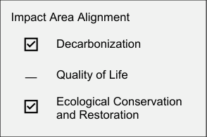
Materials and Resources Prerequisite
PLANNING FOR ZERO WASTE OPERATIONS
MRp1
REQUIRED
INTENT
To reduce the amount of waste that is generated by building occupants and hauled to and disposed of in landfills and incinerators through reduction, reuse, and recycling services and education, and to conserve natural resources for future generations. To set the building up for success in pursuing zero waste operations.
REQUIREMENTS
| Achievement pathways | Points |
|---|---|
Commercial Interiors | N/A |
Storage and Collection of Recyclables | |
AND | AND |
Zero Waste Operations Planning | Zero Waste Operations Planning |
Comply with the following requirements:
Storage and Collection of Recyclables
Provide dedicated areas accessible to waste haulers, janitorial staff, and building occupants for the collection and storage of recyclable materials for the entire building.
-
Collection and storage areas may be separate locations.
-
Recyclable materials must include organics/food waste, mixed paper, corrugated cardboard, glass, plastics, and metals.
o Mixed recyclables are acceptable for paper, corrugated cardboard, glass, plastics,
and metals if required by local conditions.
o Space for the storage of organics/food waste recycling is required even if service is
not available at the time of building occupancy.
- Take appropriate measures for the safe collection, storage, and disposal of batteries, mercury-containing lamps, and electronic waste.
Zero Waste Operations Planning
Include design details, maintenance manuals, and/or other resources from the design and construction team that help facilitate building occupants and operators to meet highperformance waste prevention and recycling goals once in operation.
U.S. Green Building Council LEED v5 Reference Guide for Interior Design and Construction, April 2025 Launch Edition 235
PDF Page 247
REQUIREMENTS EXPLAINED
The goal for the prerequisite is to minimize waste generated by building occupants and to implement strategies in reducing, reusing, and recycling waste throughout the building’s life cycle. This includes incorporating design measures that prioritize waste prevention, material reuse, and effective waste management. It also encourages project teams to thoughtfully consider and plan for the access requirements of all individuals who will service and use the building. Additionally, teams should anticipate and accommodate the operational needs necessary for achieving zero waste by enabling effective waste diversion practices. This includes ensuring proper sorting, storage, and access solutions to facilitate recycling, composting, and other waste diversion methods, while prioritizing reuse as a key strategy.
Storage and Collection of Recyclables
Municipal solid waste has become a growing concern as the volume of waste generated in the U.S. continues to increase. [63 ] An obstacle to effective recycling in buildings is the lack of convenient, dedicated physical spaces for collection. Incorporating recycling infrastructure early in the design process encourages successful recycling once operations begin. Well-designed and accessible waste management infrastructure is intuitive - easy to locate, reach, and use for all occupants, regardless of physical ability or mobility, and anticipates how and where waste will be discarded by occupants. Steps should be taken to also address concerns for noise, odor, and vectors.
Recycling includes traditional materials like glass, plastic, and metals. It also includes organic materials such as food scraps, paper products, and landscape materials. Organic materials collected in buildings can be composted on-site or off-site. Composting can occur at multiple scales and locations: small-scale systems might include basic compost piles or bins, while large-scale operations involve centralized, commercial facilities that process organic waste from an entire region.
To meet the prerequisite, teams must provide dedicated area(s) for recyclable items, including organics (compostables), mixed paper, corrugated cardboard, glass, plastics, and metals. Teams should work with the owner and architects to provide sufficient collection and storage space for all required recyclables based on the building size, occupants, and local recycling markets. In many places, recycling of various materials is required by laws or regulations. Project teams are encouraged to check for local requirements and service vendors to ensure maximal waste diversion.
63 “Municipal Solid Waste Factsheet”, University of Michigan Center for Sustainable Systems, (2024), accessed March 31, 2025, https://www.css.umich.edu/publications/factsheets/material-resources/municipal-solid-waste-factsheet.
U.S. Green Building Council LEED v5 Reference Guide for Interior Design and Construction, April 2025 Launch Edition 236
PDF Page 248
Given the substantial GHG emissions from discarded organic waste in landfills (from methane production), it is essential to plan space for composting organic materials generated by occupants, even if composting services are not immediately available at time of building occupancy. For organics collection, some material processors will encourage paper products to be recycled separately (such as office paper placed in mixed-paper recycling bins and excluded from food scraps collection). Check with local authorities for guidance on best practices for mixed paper or cardboard and other forms of organics composting.
To meet the prerequisite, project teams must provide an adequate amount of dedicated space for recycling with the appropriate infrastructure to handle such recycling. This includes planning for the installation of collection systems or bins for the collection of recyclable materials that are expected to be collected by the building and sent for recycling at time of occupancy. These installed bins or collection systems can be based on current service offerings in the project region.
Commingled recycling bins (excluding organics) are acceptable if the local municipality or recycling vendor allows commingled recycling, though commingled recycling tends to reduce the quality of diverted materials and leads to lower overall recovery rates. Therefore, source separation of recycled material types is encouraged to maximize diversion rates and help meet zero waste goals, but is not required unless separate streams are required by local regulations or guidelines.
The increasing volume of electronic waste (e-waste), such as computers, cameras, printers, and keyboards, has become a growing environmental concern. The disposal procedure for e-waste is more hazardous than cardboard, glass, plastic, metals, and paper. Therefore, identifying safe storage areas, recycling facilities, and haulers that can process e-waste is important. Teams must indicate space dedicated to the storage and collection of recyclables, composts, and ewaste areas on a floor plan and describe how these spaces will be serviced and accessed safely by building occupants and staff.
Project teams are recommended to follow the TRUE [64] waste hierarchy framework that prioritizes waste management actions to minimize environmental impact and conserve resources. It ranks waste management strategies from most to least preferred, focusing on reducing waste generation and maximizing resource recovery before resorting to disposal, in this order:
-
Reduce . Minimizing waste at the source (e.g., use fewer materials and resources)
-
Reuse . Extending the life of products by using them more than once
64 “TRUE”, Green Business Certification, Inc. (GBCI), accessed March 31, 2025, https://true.gbci.org/.
U.S. Green Building Council LEED v5 Reference Guide for Interior Design and Construction, April 2025 Launch Edition 237
PDF Page 249
-
Recycle . Transforming waste material into new products
-
Compost . Decomposing organic waste into nutrient-rich soil
-
Anaerobic Digestion . Breaking down organic material into a form of nutrient-rich liquid for soil application; does not necessarily equal composting.
-
Zero Waste Operations Planning
Project teams must include design details, maintenance manuals, and other resources in a plan to help building operators to minimize waste and implement recycling practices post-occupancy. Projects should consider implementing reusable infrastructure, such as refillable dispensers, reusable service ware, and reusable event items, while also establishing comprehensive systems for waste diversion, including take-back programs for specialty items and user-friendly sorting stations with adequate storage.
The plan should consist of materials for training staff and contractors, such as literature, presentations, and onboarding training resources. These resources may cover topics like designated recycling and composting areas, waste separation procedures, and proper disposal guidelines. It can include strategies to help with waste prevention, materials recovery, and operational procedures that support zero waste objectives.
DOCUMENTATION
| Project types | Options | Paths | Documentation |
|---|---|---|---|
All | Storage and Collection of Recyclables | All | Proof of space for recycling and composting |
All | Storage and Collection of Recyclables | All | Pictures of final spaces incorporated into the building with signage |
All | Storage and Collection of Recyclables | All | Narrative describing the dedicated recycling storage areas for the project, including the size, accessibility, and expected volume for the project |
All | Zero Waste Operations Planning | Zero Waste Operations Planning | Zero waste plan, including any resources used to train staff and contractors (e.g., literature, presentation, onboarding training, etc.) |
REFERENCED STANDARDS
U.S. Green Building Council LEED v5 Reference Guide for Interior Design and Construction, April 2025 Launch Edition 238
PDF Page 250
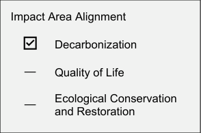
Materials and Resources Prerequisite
QUANTIFY AND ASSESS EMBODIED CARBON
MRp2
REQUIRED
INTENT
To quantify embodied carbon impacts of materials used in commercial interiors projects and assess the top sources of embodied carbon.
REQUIREMENTS
| Achievement pathways | Points |
|---|---|
Commercial Interiors | N/A |
Embodied Carbon | |
AND | AND |
High-Priority Embodied Carbon Sources | High-Priority Embodied Carbon Sources |
Comply with the following requirements:
Embodied Carbon
Quantify the embodied carbon impacts (global warming potential, or GWP) and quantities of interior materials for the project. Include the following when included in the scope of work: gypsum wallboard, flooring, insulation, wood and wood composites, wall framing, ceiling systems, concrete, metals, and paints and coatings. Project teams may include furniture at their discretion.
Quantify the cradle-to-gate (A1–A3) embodied carbon emissions for each material defined as the product’s GWP/unit times the amount of material used.
Alternatively, projects using life cycle assessment or embodied carbon software tools may report A1–A3 results from their tool.
AND
High-priority Embodied Carbon Sources
Identify the top three sources of embodied carbon on the project and describe how projectspecific strategies were considered to reduce the impacts of these hot spots.
U.S. Green Building Council LEED v5 Reference Guide for Interior Design and Construction, April 2025 Launch Edition 239
PDF Page 251
REQUIREMENTS EXPLAINED
This prerequisite ensures that all projects become acquainted with embodied carbon and gain a basic understanding of how to quantify and measure it. It also highlights the critical role of material selection, emphasizing that informed choices across major material categories are essential to achieving meaningful reductions in embodied carbon. The prerequisite aims to raise awareness of the upfront embodied carbon associated with key materials used in interior finishes and materials of a project. This prerequisite does not mandate reductions in embodied carbon.
Project teams can achieve this prerequisite in two ways:
- As a stand-alone assessment conducted for projects not attempting the MRc2: Reduce Embodied Carbon
OR
- As an output from projects that are attempting the MRc2: Reduce Embodied Carbon .
The intention is that many projects will attempt to earn points from MRc2: Reduce Embodied Carbon and therefore will use the analysis as the documentation for this prerequisite with no additional analysis needed.
In addition, all projects will need to summarize the top three sources of embodied carbon in their project and describe what strategies in the project were considered to reduce the impact of these hotspots.
Embodied Carbon
The extraction and manufacturing phases of building materials account for a substantial portion of embodied carbon emissions, primarily due to energy-intensive raw material extraction, transportation from manufacturers to construction sites, and the waste produced during manufacturing. Projects that seek carbon reductions in the early design phases (schematic design and design development) can make the most significant decisions to reduce embodied carbon early in projects, not after design is complete, when material substitutions may not be allowed or become cost-prohibitive. The owner, designers, and contractors can collectively make decisions to reduce the impacts a building’s materials will have on the environment by using a fully integrated and collaborative design process.
U.S. Green Building Council LEED v5 Reference Guide for Interior Design and Construction, April 2025 Launch Edition 240
PDF Page 252
Quantify Embodied Carbon Impacts
Quantifying the embodied carbon impacts provides a holistic assessment across major material groups within the project: interior materials (i.e., gypsum wallboard, flooring, insulation, wood and wood composites, wall framing, ceiling systems, concrete, metals, paints, and coatings). Project teams may include furniture at their discretion. The GWP is calculated for quantities of all major materials within the project scope of work. By summing up the impacts of all materials, the project team can achieve a detailed understanding of the embodied carbon for each product group, enabling informed decisions to reduce the project’s overall environmental impact.
Teams must use building project documents, including construction drawings and specifications, or software tools to group materials into a bill of materials (BOM) of interior materials and furniture used on the project. The BOM must encompass all substantial elements within the LEED project boundary. As a minimum requirement, the BOM should cover materials such as gypsum wallboard, flooring, insulation, wood and wood composites, wall framing, ceiling systems, concrete, metals, paints, and coatings. Project teams may include furniture at their discretion. Quantities may come from as-built data or estimated quantities from the design phase.
Quantify the Cradle-to-gate Embodied Carbon Emission
Quantifying the Cradle-to-gate (A1–A3) embodied carbon emissions for each material focuses on emissions associated with raw material extraction (A1), transportation to the manufacturing site (A2), and the manufacturing processes (A3). Calculate the GWP based on the cradle-togate (A1–A3) impacts for each applicable material used in the project. This involves multiplying the GWP/unit (from EPDs or default values) by the quantity of each material.
Teams will locate EPDs to determine the embodied carbon values for each material. If EPDs are unavailable, teams may use industry-standard defaults provided by regional data sources or integrated within qualifying software tools. Projects should follow a hierarchy of data: first, use specific EPDs for the product, as published by the manufacturer. If a product-specific EPD is not available, use the U.S. Environmental Protection Agency (U.S. EPA) default values when available. Next, refer to the most recent Carbon Leadership Forum (CLF) Material Baselines report. [65] Then, consult other credible and widely recognized publications, including industrywide EPDs relevant to the project region.
65 “Carbon Leadership Forum Material Baselines for North America / August 2023”, Carbon Leadership Forum, (2023), accessed March 31, 2025, https://www.carbonleadershipforum.org/clf-material-baselines-2023/.
U.S. Green Building Council LEED v5 Reference Guide for Interior Design and Construction, April 2025 Launch Edition 241
PDF Page 253
Tools and databases A growing number of tools and databases are becoming available for calculating embodied carbon of whole-project interiors and finishes, though the tools are not yet as well known or developed as whole-building LCA tools. The data sources within these databases vary: EPDs, manufacturer-provided data, academic research, industry statistics, government publications, and other databases. These differences in data sources can influence the accuracy and comparability of the results. Some databases account for regional variations in life cycle inventory (LCI) data, baseline LCA values, and EPD information, while others may only support analysis within specific countries or regions.
Teams should select tools and databases that best align with their project needs, considering factors such as geographic relevance, data accuracy, and software compatibility. Some common whole building life-cycle assessment (WBLCA ) tools in North America may have data for interiors, including Athena Impact Estimator [66] , One Click LCA [67,] and Tally [68.] Some commonly used material and product databases include Embodied Carbon in Construction Calculator (EC3)69, Ecomedes [70] , and Sustainable Minds Transparency Catalog [71] . All of these continue to add more finishes and interior product categories every year.
Results of the Embodied Carbon Quantification
When tallied up, the results of the embodied carbon quantification represent the total embodied carbon calculated from the cradle-to-gate (A1–A3) stages of materials used in the project’s interior scope of work. With the results of this quantification, teams are able to identify the high GWP materials early in design and prioritize alternatives or modifications.
High-priority Embodied Carbon Sources
An incredible opportunity exists for embodied carbon reduction in high-impact materials for interiors projects through policy, design, material selection, and specification. For example, selecting low embodied carbon options for finish materials like flooring, ceiling tiles, and paints can result in a 5% embodied carbon reduction without added cost. [72] Deeper reductions can be achieved by targeting materials with highest impacts based on EPDs and other data gathered
66 “Impact Estimator for Buildings”, Athena Sustainable Materials Institute, 2022, https://calculatelca.com/software/impact-estimator/. 67 “One Click LCA”, One Click LCA Ltd., 2025, https://oneclicklca.com/software/design-construction. 68 “Tally”, Building Transparency, 2023, https://choosetally.com/. 69 “Embodied Carbon in Construction Calculator” (EC3), Building Transparency, 2024, https://www.buildingtransparency.org/. 70 “Ecomedes”, Ecomedes, Inc., 2024, https://products.ecomedes.com/. 71 “Sustainable Minds Transparency Calculator”, Sustainable Minds® Transparency Catalog™, https://transparencycatalog.com/search 72 Esau, R., Jungclaus, M., Olgyay, V. & Rempher, A. (2021, July), RMI, Reducing Embodied Carbon in Buildings, https://www.rmi.org/wp-content/uploads/dlm_uploads/2021/08/Embodied_Carbon_full_report.pdf.
U.S. Green Building Council LEED v5 Reference Guide for Interior Design and Construction, April 2025 Launch Edition 242
PDF Page 254
as part of this prerequisite and then writing specifications to required low embodied carbon alternatives.
Projects must identify the three primary contributors to embodied carbon, focusing on materials or processes with the highest carbon emissions. For each of these key sources, provide a detailed explanation of how the team evaluated and implemented project-specific strategies to reduce their environmental impact. A hot spot analysis is mandatory to identify the most carbonintensive materials, allowing teams to focus on areas with the greatest potential for impactful reductions.
DOCUMENTATION
| Project types | Options | Paths | Documentation |
|---|---|---|---|
All | Embodied Carbon | All | Bill of Materials (worksheet) that lists the quantities of interior materials and furniture used on the project, along with the cradle-to-gate (A1–A3) embodied carbon emissions for each material. Provide a description of the data sources utilized to determine the embodied carbon values for each material. Include justification of baselines (regional, industry, similar construction type, etc.) utilized if EPA GSA, CLF, or other recommended embodied carbon values are not available. Projects using life-cycle assessment or embodied carbon software tools may report the results from their tool. |
All | Embodied Carbon | All | Provide alternative documentations if EPDs are not available. |
All | High- Priority Embodied Carbon Sources | High- Priority Embodied Carbon Sources | Document the top three high priority embodied carbon sources and describe the solutions considered to reduce the impacts. |
REFERENCED STANDARDS
- Material Requirements, LEC Program Details, U.S. General Services Administration (https://www.gsa.gov/real-estate/gsa-properties/inflation-reduction-act/lec-programdetails/material-requirements)
U.S. Green Building Council LEED v5 Reference Guide for Interior Design and Construction, April 2025 Launch Edition 243
PDF Page 255
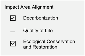
Materials and Resources Credit
INTERIOR MATERIALS REUSE
MRc1
1–4 points
INTENT
To discourage unnecessary demolition and encourage the on-site reuse of existing interior elements and furniture, and to incorporate reused materials into new project design wherever possible. Such practices reduce embodied carbon, keep materials in circularity, reduce demand for virgin material sourcing, preserve cultural resources and histories, and foster markets for reused materials.
REQUIREMENTS
| Achievement pathways | Points |
|---|---|
Commercial Interiors | 1–4 |
Option 1. Reuse Existing Interior and Minimize Renovation | 1–4 |
Path 1. Furniture and Interior Nonstructural Elements Reuse | 1–4 |
OR | |
Path 2. Furniture Reuse | 1–2 |
AND/OR | |
Option 2. Materials Reuse | 1–3 |
Demonstrate reduced environmental impacts during initial project decision-making by reusing existing building resources and by incorporating off-site reused materials into the project design. For projects with deconstruction or demolition in scope, conduct a salvage assessment prior to deconstruction or demolition activities and identify materials that can be retained on-site or diverted off-site to reuse markets.
NOTE: Materials sent for off-site reuse contribute to waste diversion in MRc5: Construction and Demolition Waste Diversion. Materials retained on-site or acquired from off-site sources and incorporated into the project contribute to this credit.
Achieve points through building and/or material reuse. Pursue Option 1 and/or Option 2 for a maximum of four points.
Option 1. Reuse Existing Interior and Minimize Renovation (1–4 points)
Maintain the existing interior nonstructural elements and furniture. Only materials that remain in place (on-site reuse) are included in this credit option. On-site reuse can include materials that come from the same project owner’s stockpile or warehouse but excludes any off-site reused materials incorporated into the project that originate from external sources. Hazardous materials remediated as a part of the project must be excluded from the calculation.
U.S. Green Building Council LEED v5 Reference Guide for Interior Design and Construction, April 2025 Launch Edition 244
PDF Page 256
PATH 1. FURNITURE AND INTERIOR NONSTRUCTURAL ELEMENTS REUSE (1–4 POINTS)
Compile the total cost for the project’s on-site reused and new nonstructural elements and furniture, pricing reused elements as if they were new. Include all the following elements in the project, as applicable to the scope of work: flooring, walls, ceilings, insulation, and furniture. Determine the cost of the elements of the project that are reused on-site and calculate the percentage of the total value of the project, including both new and reused. Points are awarded according to Table 1.
Table 1. Points for on-site reuse of interiors and furniture as a percent of total
| Percent of furniture and interior systems reused on-site (by cost) | Points |
|---|---|
| 10% | 1 |
| 20% | 2 |
| 30% | 3 |
| 40% | 4 |
OR
PATH 2. FURNITURE REUSE (1–2 POINTS)
Compile the total cost for the project’s furniture that is reused on-site. Include the total project cost for reused and new furniture, pricing the reused furniture as if it were new. Determine the percentage of reused furniture based on cost and earn points according to Table 2.
Table 2. Points for furniture reuse
| On-site furniture reuse (by cost) | Points |
|---|---|
| 20% | 1 |
| 40% | 2 |
AND/OR
Option 2. Material Reuse (1–3 points)
Survey and identify material procurement opportunities from off-site reuse and/or salvage sources. Incorporate reused materials into the project design. Specific targeted reuse materials are valued higher because they have high impacts (embodied carbon or pollution) and are hard to recycle, and because significant amounts of these materials end up in landfill.
U.S. Green Building Council LEED v5 Reference Guide for Interior Design and Construction, April 2025 Launch Edition 245
PDF Page 257
Earn points according to Tables 3 and 4. Calculate the percentage reused per material type according to Equation 1.
Table 3. Points for salvaging materials
| Salvage strategies and percentages | Points |
|---|---|
| Incorporate off-site reused materials for at least 25% of 1 targeted material type OR Incorporate off-site reused materials for at least 25% of 2 other material types OR Incorporate an equivalent weighted average of targeted and other material reuse types | 1 point |
Incorporate off-site reused materials for at least 50% of 1 targeted material type OR Incorporate off-site reused materials for at least 25% of 2 targeted material types OR Incorporate off-site reused materials for at least 25% of 4 other material types OR Incorporate an equivalent weighted average of targeted and other material reuse types | 2 points |
Incorporate off-site reused materials for at least 75% of 1 targeted material type OR Incorporate off-site reused materials for at least 50% of 2 targeted material types Or Incorporate an equivalent weighted average of targeted and other material reuse types | 3 points |
Table 4. Salvage material types and correlating units
| Material type | Unit |
|---|---|
Targeted Materials | Targeted Materials |
Carpeting | Surface area |
Ceilings | Surface area |
Furniture (ancillary and systems) | Count, weight, volume, or floor area |
Other Materials | Other Materials |
Dimensional lumber | Board foot or linear |
Doors | Count |
Casework | Linear |
Floor-covering materials (not including carpet) | Surface area |
Lighting fixtures | Count |
Plumbing fixtures | Count |
Mechanical equipment | Count |
Door hardware | Count |
Project defined other; must be permanently installed | Project defined |
Equation 1. Reuse % per material type
Equation 1. Reuse % per material type Reuse % per material type = Amount of material type reused / Total amount of material type in
commercial interiors scope
U.S. Green Building Council LEED v5 Reference Guide for Interior Design and Construction, April 2025 Launch Edition 246
PDF Page 258
REQUIREMENTS EXPLAINED
This credit encourages projects to reuse existing building materials. Option 1 rewards projects that reuse existing interior nonstructural elements and furniture (on-site reuse). This option offers two different pathways for projects. Path 1 addresses interior nonstructural materials and furniture, while Path 2 solely addresses furniture. Option 2 requires projects to identify opportunities to procure materials from off-site sources and rewards the reuse of both targeted and other materials.
The table below shows how different types of reuse are recognized within the LEED v5 Materials and Resources category, including their contributions to MRc5: Construction and Demolition Waste Diversion and MRc4: Building Product Selection and Procurement .
Table 1. Types of reuse and credit contributions
| Credits/Options/Paths | On-site reuse (keep materials in place or within the same project) | Procure off-site salvaged materials | Divert on-site materials to salvage markets |
|---|---|---|---|
| Credits/Options/Paths | (On-site-on-site) | (Off-site-on-site) | (On-site-off-site) |
| MRc1: Interior Materials Reuse, Option 1. Path 1. Furniture and Interior Nonstructural Elements Reuse | x | ||
MRc1: Interior Materials Reuse, Option 1. Path 2. Furniture Reuse | x | ||
MRc1: Interior Materials Reuse, Option 2. Materials Reuse | x | ||
MRc5: Construction and Demolition Waste Diversion | x | ||
MRc4: Building Product Selection and Procurement(nonstructural materials) | x | x |
Conduct salvage assessment for projects with deconstruction or demolition in scope All projects with deconstruction or demolition in scope, conduct a salvage assessment to document the quantity of materials that could be salvaged and reused on- or off-site. A salvage assessment is most useful when conducted before construction activities begin. Conducting a salvage assessment identifies valuable materials and components that can be reclaimed and reused, thus reducing waste and disposal costs. Examples of salvageable materials include clean wood, siding, roofing materials, plumbing, furniture, and light fixtures.
U.S. Green Building Council LEED v5 Reference Guide for Interior Design and Construction, April 2025 Launch Edition 247
PDF Page 259
Beyond traditional salvage yards, teams should explore creative options for material reuse, such as partnering with local organizations or marketplaces. Resources like BuildReuse.org [73], Rheaply [74], and All for Reuse [75] can connect projects to potential outlets for salvaged materials.
In addition, while conducting the salvage assessment, projects can explore local reuse sources to identify opportunities for incorporating reclaimed materials into the project (note: this strategy is rewarded in Option 2, but not eligible for contributing toward Option 1 credit achievement). Examples of available materials may include wood, carpet, tile, flooring, doors, and other finishes. These materials offer flexibility in their application and do not need to be limited to their original intended purpose. For instance, doors can be repurposed as partition walls or furniture (desktops), and windows can serve as interior clerestories between enclosed rooms.
Option 1. Reuse Existing Interior and Minimize Renovation
Reusing existing interior nonstructural elements and furniture into the project are impactful strategies to minimize the long-term environmental impact of an interior space. By prioritizing the reuse of existing materials, projects can extend the life of valuable resources and minimize the need for new raw material extraction. This, in turn, decreases the need for energy-intensive manufacturing and transportation, which helps lower embodied energy and GHG emissions.
PATH 1. FURNITURE AND INTERIOR NONSTRUCTURAL ELEMENTS REUSE
Project teams are recommended to develop drawings showing the location of existing furniture and nonstructural interior elements and identify the areas that are in good condition and are to be reused, salvaged, or refurbished on-site for the project. Reused elements may originate from the same project owner’s stockpile or warehouses that are within the owner’s control, but excludes any off-site reused materials incorporated into the project that originate from external sources (those would be captured under Option 2). Materials received as donations or by a third party are not considered part of the owner’s stockpile and are excluded from this path.
Teams are encouraged to create a list of materials for all on-site reused and new nonstructural elements and furniture. Projects can add additional product categories or materials that are within the scope of work. The list of materials serves as a comprehensive inventory, detailing quantities, material types, and sources, allowing for streamlined tracking and decision-making throughout the project.
Points are awarded based on the percentage of reused elements retained on-site by cost. Teams must quantify the existing and reused interior nonstructural elements based on final as
73 “Home page”, Build Reuse, accessed March 31, 2025, https://www.buildreuse.org/. 74 “Home page”, Rheaply, accessed March 31, 2025, https://rheaply.com/. 75 “Home page”, All For Reuse, accessed March 31, 2025, https://www.allforreuse.org/.
U.S. Green Building Council LEED v5 Reference Guide for Interior Design and Construction, April 2025 Launch Edition 248
PDF Page 260
built quantities and costing them as if they were new. When estimating the cost of reused materials, ensure that the costs reflect comparable products of similar quality, function, and condition. For example, a reused particleboard table cannot be assumed to have the same value as a new hand-carved marble and oak table. Costs must be based on reasonable comparisons to avoid overinflating or underestimating the value of reused items, ensuring transparency and fairness in the assessment process. Teams are suggested to match the reused material to a product with similar material type, design, condition, and functionality, and use sources such as salvage yards or online reuse platforms for cost comparisons.
Equation 1. Percentage of reused nonstructural elements and furniture
Equation 1. Percentage of reused nonstructural elements and furniture 𝑅 𝑅 𝑅 𝑛 𝑛 𝑛 𝑛 𝑛 𝑛 𝑛 𝑒 𝑒 𝑒 𝑒 𝑎 𝑎 𝑓 𝑓 𝑓 𝑓 𝑓 =
𝐶 𝐶 𝑜 𝑟 𝑟 𝑟 𝑛 𝑛 𝑛 𝑛 𝑛 𝑛 𝑛 𝑒 𝑒 𝑒 𝑒 𝑎 𝑎 𝑓𝑢 𝑢 𝑢 𝑢
𝑇 𝑇 𝑇 𝑐 𝑐 𝑜 𝑛 𝑛 𝑎 𝑎 𝑟 𝑟 𝑟 𝑛 𝑛 𝑛 𝑛 𝑛 𝑛 𝑛 𝑒 𝑒 𝑒 𝑒 𝑎 𝑎 𝑓 𝑓 𝑓 𝑓 𝑓 [ × 100 ]
Include all of the following elements in product categories below, as applicable to the project scope of work:
-
Flooring . The flooring product category includes all types of hard and soft surface flooring (carpet, ceramic, vinyl, rubber, engineered, solid wood, laminates), wall base, underlayment, and other floor coverings. Subflooring is excluded.
-
Wall panels . The wall panels product category includes all nonstructural wall elements (framing and drywall), finish wall treatments (wall coverings, wall paneling, wall tile), surface wall structures such as gypsum or plaster, cubicle/curtain/partition walls, trim, doors, hardware, frames, windows, and window treatments. Removable/interchangeable fabric panels and vertical structural elements are allowed to be included in the calculations. Structural elements such as wall framing, curtain walls, brick or concrete are excluded.
-
Ceilings . The ceilings product category includes all ceiling panels, ceiling tile, surface ceiling structures such as gypsum or plaster, suspended systems (including canopies and clouds), and glazed skylights. Overhead structural elements (exposed, finished, and unfinished) are excluded.
-
Insulation . The insulation product category includes all thermal and acoustic boards, batts, rolls, blankets, sound attenuation fire blankets, foamed-in place, loose-fill, blown, and sprayed insulation
-
Furniture . The furniture product category includes all built-in and stand-alone furniture items, furniture systems, and cabinetry.
U.S. Green Building Council LEED v5 Reference Guide for Interior Design and Construction, April 2025 Launch Edition 249
PDF Page 261
PATH 2. FURNITURE REUSE
Teams are encouraged to conduct an inventory of existing furniture and furnishings early in the design process to determine what products could be incorporated into the project design. Teams should develop a tracking list of all actual and potentially reusable furniture and furnishings to help efficiently identify, document, and manage items that can be incorporated into the project. Teams must d etermine the total cost of the project’s furniture and calculate the percentage of reused items used. When determining the total cost of reused furniture, ensure that the costs reflect comparable products of similar quality and condition. The cost assigned to each reused item should be based on its current state and market value relative to the equivalent product. Resources like Rheaply and All for Reuse provide an exchange platform to share, buy, or sell reused furniture and can be good sources of cost information.
Equation 2. Percentage of reused furniture
𝑅 𝑅 𝑅 𝑓 𝑓 𝑓 𝑓 𝑓𝑓=
𝐶 𝐶 𝑜 𝑟 𝑟 𝑟 𝑓 𝑓 𝑓 𝑓 𝑓
𝑇 𝑇 𝑇 𝑐 𝑐 𝑜 𝑟 𝑟 𝑟 𝑎 𝑎 𝑛 𝑛 𝑓 𝑓 𝑓 𝑓 𝑓 [ × 100 ]
𝐶 𝐶 𝑜 𝑟 𝑟 𝑟 𝑓 𝑓 𝑓 𝑓 𝑓
Option 2. Materials Reuse
This option rewards projects for incorporating off-site reused elements into the building. The sources for reused materials can be from on-site or gathered off-site from vendors, other projects, salvage yards, donations, and can leverage local resources and community networks to locate quality materials. For instance, organizations such as Habitat for Humanity ReStores [76] and Salvage Yards also offer gently used and reclaimed furniture at discounted prices.
Teams are encouraged to maintain a set of photos to document and verify the reuse of materials. These include photos per material being reused which includes a record of the materials, both before and after reuse, and images of materials being processed or repaired for reuse (if applicable).
In the credit Table 2, specific materials are targeted due to their higher impacts and the potential for greater reuse and recovery in the near term. The prioritization of these materials is based on several criteria, including high embodied carbon, toxic impacts in landfills, and significant potential for recovery in existing or emerging salvage and reuse markets. These targeted materials receive a 2x multiplier compared to other reused materials. However, all forms of reuse are recognized in this credit and can be quantified in the various material types listed in Table 2, or the “project defined other” category.
76 “Home page”, Habitat for Humanity ReStores, accessed March 31, 2025, https://www.habitat.org/restores.
U.S. Green Building Council LEED v5 Reference Guide for Interior Design and Construction, April 2025 Launch Edition 250
PDF Page 262
DOCUMENTATION
| Project types | Options | Paths | Documentation |
|---|---|---|---|
All | Option 1 | Path 1. Furniture and Interior Nonstructural Elements Reuse | Worksheet demonstrating the percentage of furniture and interior systems reused onsite. |
All | Option 1 | Path 2. Furniture Reuse | Worksheet demonstrating the percentage of furniture reuse. |
All | Option 2 Material Reuse | Worksheet demonstrating the percentage of off-site reuse. |
REFERENCED STANDARDS
U.S. Green Building Council LEED v5 Reference Guide for Interior Design and Construction, April 2025 Launch Edition 251
PDF Page 263
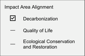
Materials and Resources Credit
REDUCE EMBODIED CARBON
MRc2
1–4 points: A 10% reduction of embodied carbon is required for LEED Platinum projects.
INTENT
To reduce the embodied carbon impacts of materials used in commercial interiors projects.
REQUIREMENTS
| Achievement pathways | Points |
|---|---|
Commercial Interiors | 1–4 |
Option 1. Reduce Embodied Carbon of New Materials | 1–4 |
AND/OR | |
Option 2. Interiors Life-Cycle Assessment | 1–4 |
Option 1. Reduce Embodied Carbon of New Materials (1–4 points)
Points are awarded according to Table 1. In dustry averages for material categories are defined by the U.S. Environmental Protection Agency, the most recent Carbon Leadership Forum Material Baselines report, or similarly robust and widely recognized publications and industrywide environmental product disclosures applicable to the project region.
Projects must track the GWP/unit of the materials installed, reconciling the design-phase embodied carbon intensities if materials or GWP values have changed. The reconciliation of material quantities is not necessary unless quantities have changed more than 10% from design through construction.
Projects must use project-specific material quantities and identify product-specific or facilityspecific Type III EPDs for covered materials to demonstrate reductions. Biogenic carbon may only be included for calculations that include C-stage emissions.
Table 1. Points awarded for embodied carbon assessment and reduction
| Col1 | Points |
|---|---|
| Meet baseline or industry average | 1 |
| 10% reduction | 2 |
| 20% reduction | 3 |
| 30% reduction | 4 |
AND/OR
U.S. Green Building Council LEED v5 Reference Guide for Interior Design and Construction, April 2025 Launch Edition 252
PDF Page 264
Option 2. Interiors Life Cycle Assessment (1–4 points)
For tenant improvements and renovation projects, conduct a cradle-to-grave (modules A–C, excluding operating energy and operating water-related energy) life cycle assessment (LCA) of the project’s entire scope of work, including structure and enclosure (if any); ceiling; wall; flooring; and interior partition assemblies, including acoustic insulation, metal framing, finishes, coatings, and furniture. LCA data sets must be compliant with ISO 14044 . Biogenic carbon may only be included for calculations that include C-stage emissions. Include results for the following impact categories in the Interiors LCA report:
-
GWP (greenhouse gases), in kg CO2e
-
Depletion of the stratospheric ozone layer, in kg CFC-11e
-
Acidification of land and water sources, in moles H [+] or kg SO2e
-
Eutrophication, in kg nitrogen eq or kg phosphate eq
-
Formation of tropospheric ozone, in kg NOx, kg O3 eq, or kg ethene
-
Depletion of nonrenewable energy resources, in MJ using CML/depletion of fossil fuels in TRACI
Compare results to a baseline developed for the project and earn points according to Table 2.
Table 2. Points awarded for interiors LCA
| Pathway | Threshold | Points |
|---|---|---|
| Path 1 | Conduct an LCA of the project’s complete interior design and compare against a baseline interiors project. | 1 |
| Path 2 | Meet the requirements of Path 1 and demonstrate at least a 10% reduction in GWP compared with the interiors project baseline | 2 |
| Path 3 | Meet the requirements of Path 1 and demonstrate reductions compared with the interiors project baseline of at least 20% for GWP and demonstrate at least a 10% reduction in two additional targeted impact categories | 4 |
REQUIREMENTS EXPLAINED
The goal of this credit is to raise awareness about the upfront embodied carbon associated with interior finish materials. It aims to promote using various tools and resources to reduce embodied carbon for the interior scope of work. There are multiple options for compliance and points are earned by evaluating the embodied carbon of materials and demonstrating a reduction of GWP. This credit is meant to provide flexibility while incentivizing the completion of a life cycle analysis of the project interior based on software tools and/or product research through EPD analysis.
U.S. Green Building Council LEED v5 Reference Guide for Interior Design and Construction, April 2025 Launch Edition 253
PDF Page 265
Option 1. Reduce Embodied Carbon of New Materials
Projects can earn points by demonstrating a reduction in embodied carbon. The reduction is measured by comparing the project’s total embodied carbon to the calculated industry average. Points are awarded based on the extent to which the project’s embodied carbon is lowered relative to this benchmark, encouraging the use of low-carbon strategies such as material optimization, specification of products with lower embodied carbon impacts, and sourcing reused or salvaged materials.
To achieve this option, project teams will create a bill of materials that lists all the major materials used in the scope of work, their material quantities, embodied carbon intensities, and unit of materials in the project. For each material, the worksheet should multiply the material quantity by its embodied carbon intensity to calculate the total embodied carbon contribution for that material. Points will be awarded according to Table 1 in the credit and the accompanying embodied carbon reductions achieved.
Option 2. Interiors Life Cycle Assessment
This pathway is intended to reward projects that seek embodied carbon reductions by conducting an interiors LCA. The most significant decisions can be made to reduce embodied carbon early in projects, not after design is complete, when material substitutions may not be allowed or may become cost-prohibitive. Using a fully integrated and collaborative design process, decisions can collectively be made by the owner, designers, and contractors to substantially cut embodied carbon emissions.
The analysis can be implemented by utilizing software tools that include interior assemblies, by gathering EPDs or product-specific LCAs for interior products, or through a combination of both approaches. The LCA process must be compliant with ISO 14044 . Tools and data may have limitations; therefore, project teams are advised to document all assumptions if a full analysis is not possible. At a minimum, project teams pursuing this credit must:
-
Define the project boundary and scope of work.
-
Provide information on where life cycle data was obtained (document data sources).
-
Demonstrate how the LCA impacts were quantified.
-
Include modules A-C in the system boundary at a minimum.
-
Include results for all impact categories listed in the credit
-
Exclude operational energy and operating water-related energy
-
LCA data sets must be compliant with ISO 14044 .
U.S. Green Building Council LEED v5 Reference Guide for Interior Design and Construction, April 2025 Launch Edition 254
PDF Page 266
The team must develop a baseline interior LCA for the project and demonstrate that both the baseline and the proposed project are of the same relative size, function, operating energy use, system boundaries, and service life. Baseline assumptions must be based on standard design and material selection for the project location and building type. Use the same life cycle assessment software tools and data sets to evaluate both the baseline and the proposed interiors scope and report all listed impact categories.
If a team iterates early in design and makes changes to create a lower embodied carbon design, they may utilize their early design iteration as a baseline given that it aligns with the comparative requirements listed above. A team may also make a copy of their proposed design which includes low embodied carbon materials and actual EPD data (for example), and use that copy to develop a baseline scenario by replacing materials with appropriate regional default or average material intensity values and recalculating the results. Points are awarded by providing a comparison between the baseline model and the proposed design and calculating reductions.
DOCUMENTATION
| Project types | Options | Paths | Documentation |
|---|---|---|---|
All | Option 1. Reduce Embodied Carbon of New Materials | Bill of Materials worksheet that includes the materials and quantities used, embodied carbon intensities, and unit of materials in the project. | |
All | Option 2. Interiors LifeCycle Assessment | Provide baseline LCA report and Proposed Design LCA report. | |
All | Option 2. Interiors LifeCycle Assessment | Compare the outputs of the baseline vs. proposed reports to identify reductions. |
REFERENCED STANDARDS
-
Embodied Carbon in Construction Calculator (EC3) (buildingtransparency.org/ec3/users/me)
-
The ICE Database (circularecology.com/embodied-carbon-footprint-database.html)
U.S. Green Building Council LEED v5 Reference Guide for Interior Design and Construction, April 2025 Launch Edition 255
PDF Page 267
Materials and Resources Credit
LOW-EMITTING MATERIALS
MRc3
1–4 points
INTENT
To reduce concentrations of chemical contaminants that can damage air quality and the environment. To protect human health and the comfort of installers and building occupants.
REQUIREMENTS
| Achievement pathways | Points |
|---|---|
Commercial Interiors | 1–4 |
Low-Emitting Material Criteria | 1–4 |
Specify and install permanent products, paints, coatings, adhesives, sealants, flooring, walls, ceilings, insulation, furniture, and/or composite wood products that meet the low-emitting criteria. Points are awarded according to Table 1 below.
Table 1. Thresholds for low-emitting materials
| Number of product categories | Threshold | Points |
|---|---|---|
| 2 | > 90% of all products in each product category | 1 |
| 4 | > 90% of each additional product category | 2 |
| 6 | > 80% of each product category | 3 |
| 8 | > 80% of each product category | 4 |
Product categories The following products and materials are not applicable to the low-emitting materials product categories: structural elements, equipment related to fire suppression, HVAC (including ductwork), plumbing, electrical, conveying and communications systems, poured concrete, structural framing, structural insulated panels, and water-resistive barriers (i.e., material installed on a substrate to prevent bulk water intrusion).
Paints and coatings
-
Paints and coatings, by volume, cost, or surface area, must meet the volatile organic compound (VOC) emissions evaluation criteria.
-
The paints and coatings product category includes all interior paints and coatings wetapplied on-site.
U.S. Green Building Council LEED v5 Reference Guide for Interior Design and Construction, April 2025 Launch Edition 256
PDF Page 268
- Exclude foamed-in-place and sprayed insulation (include in insulation category).
The following products and materials are applicable:
Adhesives and sealants
-
Adhesives and sealants, by volume or cost, must meet the VOC emissions evaluation criteria.
-
The adhesives and sealants product category includes all interior adhesives and sealants wet-applied on-site, including those used to install air or vapor barrier membranes and floor-setting materials.
Flooring
-
Nonstructural flooring materials, by surface area or cost, must meet the VOC emissions evaluation criteria.
-
The flooring product category includes all types of hard and soft surface flooring finishes (e.g., carpet, ceramic tile, vinyl, rubber, engineered wood, solid wood, stone, and laminate), raised flooring systems, entryway (“walk-off”) systems, area rugs, wood subflooring, underlayments, sandwich panels, and air barrier membranes and vapor barrier/vapor retarder membranes (if used inside an air barrier membrane).
-
Exclude poured concrete, composite wood subflooring (include in the composite wood category, if applicable), and wet-applied products applied on the floor.
Walls
-
Nonstructural wall materials, by surface area or cost, must meet the VOC emissions evaluation criteria.
-
The walls product category includes all finish wall treatments (e.g., wall coverings and wall tile), finish carpentry (e.g., millwork, paneling, railings, and trim/moldings), gypsum wallboard, wall base/skirting, interior and exterior doors, nonstructural wall framing, and nonstructural sandwich panels.
-
Exclude wet-applied products applied on the wall, case goods, cabinetry (include in the furniture category), countertops (include in the furniture category), bathroom accessories, door hardware, and curtain wall and storefront systems.
Ceilings
-
Nonstructural ceilings materials, by surface area or cost, must meet the VOC emissions evaluation criteria.
-
The ceilings product category includes all types of ceiling finishes (e.g., ceiling panels and ceiling tile), suspension grids, surface ceiling structures (such as gypsum wallboard or plaster), suspended systems (including canopies and clouds), and nonstructural sandwich panels.
U.S. Green Building Council LEED v5 Reference Guide for Interior Design and Construction, April 2025 Launch Edition 257
PDF Page 269
- Exclude wet-applied products applied on the ceiling and corrugated metal decking.
Insulation
-
Insulation products, by surface area or cost, must meet the VOC emissions evaluation criteria.
-
The insulation product category includes all thermal and acoustic boards; batts (faced and unfaced); rolls; blankets; sound attenuation fire blankets; and foamed-in-place, loose-fill, blown, and sprayed insulation.
-
Exclude insulation installed outside an air barrier membrane.
Furniture
-
Furniture in the project scope of work, by cost, area, or number of units, must meet the furniture emissions evaluation criteria or VOC emissions evaluation criteria.
-
The furniture product category includes all permanently installed office furniture, cubicles/systems furniture, seating, desks, tables, filing/storage, specialty items, beds, case goods, casework, countertops, moveable/demountable partitions, bathroom/toilet partitions, shelving, lockers, retail fixtures (including slatwall), window treatments, and furnishing items (such as nonfixed area rugs, cubicle curtains, and mattresses) purchased for the project.
-
A custom item in the furniture category is considered to meet the low-emitting criteria if all components of the finished piece, applied on- or off-site, are declared under the furniture category and meet the VOC emissions evaluation criteria. Alternatively, a custom piece meets the criteria if the finished piece, as a whole, meets the furniture emissions evaluation or VOC emissions evaluation criteria.
-
Exclude office and bathroom accessories, art, recreational items (such as game tables), cabinet and drawer hardware, and planters from the credit.
Composite wood
-
Composite wood products, by surface area or cost, must meet the formaldehyde emissions evaluation criteria.
-
The composite wood product category includes all particleboard, medium-density fiberboard (both medium density and thin), hardwood plywood with veneer, composite or combination core, and wood structural panels or structural wood products.
Low-emitting Criteria
VOC EMISSIONS EVALUATION CRITERIA
Third-party certification : Product has a qualifying third-party certification, valid at the time of product purchase, that demonstrates testing and compliance according to the California
U.S. Green Building Council LEED v5 Reference Guide for Interior Design and Construction, April 2025 Launch Edition 258
PDF Page 270
Department of Public Health (CDPH) Standard Method v1.2-2017 using the private office scenario. Products used in classrooms may be modeled using the schools or private office scenario.
OR
Qualified independent laboratory report : Product has a qualifying laboratory report (or summary) demonstrating the product has been tested no more than three years prior to the product’s purchase, according to the CDPH Standard Method v1.2-2017 . Products may use the private office scenario and must meet the VOC limits in Table 4-1 of the private office scenario. Products used in classrooms may be modeled using the schools or private office scenario.
OR
Product is inherently nonemitting, salvaged, or reused.
FURNITURE EMISSIONS EVALUATION
Product has a qualifying third-party certification, valid at the time of product purchase, that demonstrates testing according to ANSI/BIFMA Standard Method M7.1-2011 (R2021) and complies with specific sections of ANSI/BIFMA e3-2014 or e3-2024, “Furniture Sustainability Standard.” Statements of product compliance must include the exposure scenario(s).
Seating products must be evaluated using the seating scenario. Classroom furniture must be evaluated using the standard school classroom scenario. Other products should be evaluated using the open plan or private office scenario, as appropriate. The open plan scenario is more stringent.
OR
Product is inherently nonemitting, salvaged, or reused.
Salvaged and reused materials Product is more than one year old at the time of use.
If another product (including but not limited to adhesives, sealants, paints, and coatings) is applied to the inherently nonemitting material and has a separate manufacturer and cost, to the end user, from the original material, the applied product may be documented as a separate product and meet the low-emitting criteria applicable to the applied product, even if applied offsite.
If another product is applied to the inherently nonemitting/salvaged/reused material and does not have a separate manufacturer and cost, to the end user, the result is considered a new
U.S. Green Building Council LEED v5 Reference Guide for Interior Design and Construction, April 2025 Launch Edition 259
PDF Page 271
finished product that no longer qualifies as an inherently nonemitting material and is subject to the VOC emissions evaluation criteria.
FORMALDEHYDE EMISSIONS EVALUATION
Product has a qualifying third-party certification from a California Air Resources Board (CARB) approved/Environmental Protection Agency (EPA) recognized third-party certifier, valid at the time of product purchase, that demonstrates the product is one of the following:
-
Certified as ultra-low-emitting formaldehyde product under EPA’s Toxic Substances Control Act, Formaldehyde Emission Standards for Composite Wood Products (TSCA, Title VI) (EPA TSCA Title VI), or the CARB Airborne Toxic Control Measure (ATCM).
-
Certified as no-added-formaldehyde resins (NAF) product under EPA TSCA Title VI or CARB ATCM .
-
Wood structural panels manufactured according to PS 1-09 or PS 2-10 (or one of the standards considered by CARB to be equivalent to PS 1 or PS 2 ) and labeled bond classification exposure 1 or exterior.
-
Structural wood product manufactured according to ASTM D 5456 (for structural composite lumber), ANSI A190.1 (for glued laminated timber), ASTM D 5055 (for Ijoists), ANSI PRG 320 (for cross-laminated timber), or PS 20-15 (for finger-jointed lumber).
OR
Product is inherently nonemitting, salvaged, or reused.
REQUIREMENTS EXPLAINED
Installing low-emitting products can significantly reduce the quantity of indoor air contaminants in buildings. Coupled with adequate ventilation and filtration, specifying, and installing lowemitting materials is an important strategy toward improving indoor air quality.
This credit is awarded to projects with permanently installed products that meet established lowemitting criteria. Points are earned by bundling or combining products from two or more of the eight available categories: interior paint and coatings, interior adhesives and sealants, flooring, walls, ceilings, insulation, furniture, and composite wood. Projects targeting two or four product categories must achieve 90% or more of the required thresholds. Projects targeting six or eight product categories must achieve 80% or more of the required thresholds.
U.S. Green Building Council LEED v5 Reference Guide for Interior Design and Construction, April 2025 Launch Edition 260
PDF Page 272
Identifying and Specifying Low-emitting Products
The easiest way to find products with a volatile organic compounds (VOC) emissions evaluation may be to search third-party certification program databases from the qualified third-party certifiers or programs listed on the CDPH website [77] .
Other sources for finding compliant products include online aggregated product databases including Ecomedes [78] , the Sustainable Minds Transparency Catalog [79] , Building Ease [80] , and UL SPOT [81] .
Save certificates for the specified products, ensuring that the specified products and the certificates match. Make note of any certificates expected to expire before the time of purchase. Certification periods that begin after the product’s date of purchase do not demonstrate the compliance of the installed product. Track progress toward credit achievement using the LEED materials calculator.
There are international third-party programs and low-emitting third-party standards that can be used for this credit. See the Low-emitting Materials resource document on USGBC’s website.
Calculating Product Category Achievement
Project teams can decide how many product categories to attempt to earn points. To achieve a point, the project must demonstrate they meet or exceed the threshold for each product category. This can be based on cost, surface area, volume, or number of units, depending upon the measurement methods available for each product category. Project teams can choose different measurement types to measure progress toward achievement, as long as the measurement method is consistent in each product category. For example, a project could use “surface area” to demonstrate achievement of the Flooring category, “number of units” for the Furniture category, and “volume” for the Adhesives and Sealants category.
Project teams are advised to set project-achievable category goals and research, specify, and track low- or non-emitting products in those categories according to the low-emitting criteria appropriate for the products. A targeted approach focusing on specific products, or product categories, is likely to be more manageable and successful than amassing documentation for all products in every category and determining attempted categories post-construction.
77 “Home page”, California Department of Public Health, accessed March 31, 2025, https://www.cdph.ca.gov/. 78 “Home page”, Ecomedes, accessed March 31, 2025, https://www.ecomedes.com/. 79 “Sustainable Minds Transparency Catalog”, Sustainable Minds, accessed March 31, 2025, https://transparencycatalog.com/ 80 “Home page”, accessed March 31, 2025, Building Ease, https://builtworlds.com/companies/building-ease/ 81 “Home page”, UL Spot, accessed March 31, 2025, https://spot.ul.com/.
U.S. Green Building Council LEED v5 Reference Guide for Interior Design and Construction, April 2025 Launch Edition 261
PDF Page 273
Additionally, aiming for 100% compliance within a category, when possible, may simplify the process by eliminating the need to track individual units.
This credit will be documented by product category using the LEED materials calculator. Note that this calculator is combined with the MRc4: Building Product Selection & Procurement calculator . Teams are encouraged to combine submittal reviews and product vetting with the criteria found in both credits to maximize credit achievement and harmonize product selection, specification, and documentation processes.
Except for the overall product exclusions stated in the requirements, all permanently installed, nonstructural products–within and inclusive of the project’s air barrier membrane—are to be included in the calculation for the attempted categories. These products are expected to impact indoor air quality and are able to be tested in alignment with the low-emitting criteria. Products installed in parking garages and basements are to be included, as these spaces are occupied by people, even if intermittently.
Product categories which have no applicable products installed (i.e., those outside the project scope of work) are not eligible to attempt the category.
Paints and coatings This category applies to products covered in CSI Masterformat 09 90 00 Painting and Coating. Exterior painting, staining, and finish can be excluded. Exterior paint cannot be excluded from the calculation if used indoors. Aerosol products are included. Coatings also includes sealers, which are products applied to either block materials from penetrating into or leaching out of a substrate; to prevent subsequent coatings from being absorbed by the substrate; or to prevent harm to subsequent coatings by materials in the substrate (SCAQMD Rule 1113 [82] ).
VOCs in paints and coatings may be ingredients that are included to enhance product performance and shelf life, added by the contractor, or byproducts of the paint drying process. Water-based acrylic latex paints generally have lower VOCs than solvent-based paints. Lime and mineral silicate paints are most likely to be compliant with VOC limits. Paints that are advertised as antimicrobial, recycled, specialty paints (chalk, dry-erase, magnetic), and paints containing alkylphenol ethoxylates (APE) or PFAS may have compliant emissions evaluations, but introduce additional human and/or environmental hazards not addressed by this credit that the project team may wish to consider.
82 “Rule 1113: Architechtural Coatings”, South Coast AQMD, accessed March 31, 2025, https://www.aqmd.gov/home/rulescompliance/compliance/vocs/architectural-coatings.
U.S. Green Building Council LEED v5 Reference Guide for Interior Design and Construction, April 2025 Launch Edition 262
PDF Page 274
Adhesives and sealants Common adhesives and sealants used in construction are defined in SCAQMD Rule 1168 [83] . An adhesive is any substance used to bond one surface to another surface by attachment. A sealant is any material with adhesive properties that is designed to fill, seal, waterproof, or weatherproof gaps or joints between two surfaces. Note that sealers are different types of products and are to be categorized as coatings. Aerosol products are also included in this product category for LEED calculation purposes. [84]
Flooring In most buildings, the flooring category represents a significant source of indoor emissions due to the large amount of surface area covered in relation to the project. Consider reusing existing floors, where possible. When reuse is not an available option, solid wood floors, ceramic tiles, cork floors (especially pre-finished without a PVC/vinyl layer), linoleum sheet, and tile are likely to have compliant VOC emissions evaluations, as are many carpet and vinyl flooring products. Make efforts to evaluate products holistically, including, for instance, the presence of contaminants or additives like lead in recycled content products, additives included in sealants, and those used for the cleaning of flooring materials. Other concerns can relate to the project team’s environmental priorities, such as the lack of recovery and circularity options for vinyl products at end of life, or potential toxic emissions released during a product’s production. These additional multi-attribute considerations may not be addressed by product emissions criteria but are considered in the aligned MRc4: Building Product Selection and Procurement.
Walls In many buildings, the walls category represents a significant source of indoor emissions from products due to the large surface area. For instance, gypsum wallboard and doors often comprise the majority of surface area in this category. Look for compliant gypsum wallboards especially those made with natural gypsum or post-consumer recycled content. As it relates to the MRc5: Construction and Demolition Waste Diversion, consider how your project can separate unpainted gypsum wallboard cut-offs for manufacturer take-back and recycling.
Ceilings Like the walls category, the ceilings category is likely to be strongly influenced by surface area. See the walls category for notes on gypsum wallboard. Acoustical ceiling systems are also a popular material option and are likely to have compliant VOC emissions evaluation. Be sure to also include ceiling suspension grids/components, noting that powder-coated metal components are most likely to be compliant.
83 “Rule 1168 – Adhesive and Sealant Applications”, South Coast AQMD, accessed March 31, 2025, https://www.aqmd.gov/home/rules-compliance/compliance/vocs/adhesive-and-sealants. 84 “Controlling Pollutants and Sources: Indoor Air Quality Design Tools for Schools”, U.S. Environmental Protection Agency, accessed March 31, 2025,, https://www.epa.gov/iaq-schools/controlling-pollutants-and-sources-indoor-air-quality-design-tools- schools#WallsandCeilingMaterials.
U.S. Green Building Council LEED v5 Reference Guide for Interior Design and Construction, April 2025 Launch Edition 263
PDF Page 275
Insulation Insulation products with compliant testing typically include both natural and synthetic products, which include:
-
Expanded cork
-
Blown-in wood fiber
-
Cellulose
-
Fiberglass
-
Mineral wool
-
Hemp or wood fiber batts and boards
-
Unfaced fiberglass batts
-
Formaldehyde-free mineral wool batts and boards
Plastics and foam insulation products can also meet the emission criteria. Even if products meet the emissions evaluation criteria, they may still include problematic ingredients like formaldehyde and fire retardants. Consider these when selecting products and seek synergies for product optimization with the MRc4: Building Product Selection and Procurement .
Furniture The furniture category includes both systems furniture and ancillary furniture. Typically, the ability to find compliant furniture will be more available from systems furniture manufacturers, as opposed to freestanding or custom furniture. A convenient way to find products with a furniture emissions evaluation is to search product databases that list qualified third-party-verified programs and reports. See the Low-Emitting Materials resource document on USGBC ’s website.
The Business and Institutional Furniture Manufacturers Association (BIFMA) writes standards for furniture safety, ergonomics, and sustainability. Qualifying furniture products in LEED will meet the ANSI/BIFMA M7.1-2011 (R2021) Standard Test Method for Determining VOC Emissions from Office Furniture Systems, Components, and Seating [85] . In addition, products must comply with ANSI/BIFMA e3-2024e Furniture Sustainability Standard, Section 7.6.2 [86] . Laboratories that conduct the tests must be accredited under ISO/IEC 17025 [87] for the test methods they use.
85 “ANSI/BIFMA M7.1-2011 (R2021)”, BIFMA, accessed March 31, 2025, https://www.bifma.org/page/StandardsShortDesc. 86 “ANSI/BIFMA e3-2024e”, BIFMA, accessed March 31, 2025, https://www.bifma.org/page/e3-sustainability. 87 “ISO/IEC 17025”, International Organization for Standardization (ISO), accessed March 31, 2025, https://www.iso.org/ISO-IEC17025-testing-and-calibration-laboratories.html.
U.S. Green Building Council LEED v5 Reference Guide for Interior Design and Construction, April 2025 Launch Edition 264
PDF Page 276
Composite wood The composite wood product category includes all particleboard, medium density fiberboard (both medium density and thin), hardwood plywood with veneer, composite or combination core, and wood structural panels or structural wood products. Products in this category must meet the Formaldehyde Emissions Evaluation requirements in the rating system.
Formaldehyde emissions evaluation The composite wood category typically includes products that adhere to classifications and standards defined by leading industry organizations and frameworks, such as the CARB standards, which ensure low formaldehyde emissions and compliance with stringent air quality requirements. CARB maintains a list of composite wood mills that have been approved by thirdparty certifiers [88], and this list can be used to help find and specify compliant composite wood products. Certificates demonstrating a product is certified as NAF or ULEF for products must be from a CARB-Approved Third-Party Certifier [89] The certification period must cover the date of purchase.
Note that this credit does not refer to the minimum requirements of the CARB 93120 ATCM [90] or EPA TSCA Title VI [91] . It uses the more stringent requirements for ULEF resins or NAF resins as defined in the CARB ATCM . These criteria are some of the strongest available for formaldehyde emissions from composite wood. Ensure the certificate confirms this threshold is met.
The CARB composite wood definition includes wood structural panels, structural composite lumber, glued laminated timber, I-joists, cross-laminated timber, and finger-jointed lumber. These products are subject to other standards. APA – The Engineered Wood Association website [92] can be used to source compliant products.
Goods containing composite wood components, such as doors with a composite wood core, do not belong in the Composite Wood category. They are subject to the more comprehensive emissions evaluations of other categories.
88 “CARB composite wood mills”, California Air Resources Board, March 19, 2025, accessed March 31, 2025, https://ww2.arb.ca.gov/resources/documents/certified-mills-list-january-2-2025. 89 “CARB-Approved Third Party Certifiers Executive Orders”, California Air Resources Board, updated February 13, 2025, accessed March 31, 2025, https://ww2.arb.ca.gov/resources/documents/carb-approved-third-party-certifiers-executive-orders. 90 “CARB 93120 ATCM”, California Air Resources Board, accessed March 31, 2025, https://ww2.arb.ca.gov/resources/documents/airborne-toxic-control-measures. 91 “EPA TSCA Title vi”, U.S. EPA, accessed March 31, 2025, https://www.epa.gov/formaldehyde/formaldehyde-emission-standardscomposite-wood-products 92 “Home page”, The Engineered Wood Association, accessed March 31, 2025, https://www.apawood.org.
U.S. Green Building Council LEED v5 Reference Guide for Interior Design and Construction, April 2025 Launch Edition 265
PDF Page 277
VOC Emissions Evaluation Criteria
CDPH Standard Method for the Testing and Evaluation of Volatile Organic Chemical Emissions from Indoor Sources Using Environmental Chambers, v.1.2-2017 is also known as the emission testing method for California Specification 01350 [93], which is widely recognized as a leadership standard for its stringent scientific criteria and detailed specificity. It uses the chronic reference exposure levels established by the California Office of Environmental Health Hazard Assessment [94], which include some of the most stringent criteria in use, although they do not account for health condition other than cancer.
Compliant products can come from qualified third-party product certifications or from a qualified independent laboratory. See USGBC resource for list of qualifying third-party certifications.
Qualifying independent laboratory reports may also demonstrate VOC emissions evaluation; however, because they are not third-party-verified, the project team must confirm all criteria are reported on the report, including:
-
A declaration that the product has been tested according to CDPH Standard Method v1.2-2017 and complies with the VOC limits in Table 4-1 of the method
-
The total VOC results at 14 days measured as specified in CDPH Standard Method v1.2-2017
-
The test date (less than three years from date of purchase)
-
The name of the laboratory that performed the evaluation and documentation (such as accreditation number or certificate with scope of accreditation) demonstrating the accreditation under ISO/IEC 17025 for the test method
-
The modeling scenario used (must be a private office unless the product is installed in a classroom)
-
For wet-applied products, the amount of product applied in mass per surface area (during testing)
Inherently Nonemitting Criteria
Inherently nonemitting products are building materials that, owing to their composition or use in construction, do not emit VOCs and therefore do not require an emissions evaluation. Products that are inherently nonemitting include stone, ceramic, powder-coated metals, plated or anodized metal, and unfinished or untreated solid wood. For the purposes of this credit, untreated and unfinished solid wood (not engineered wood) can also be considered nonemitting
93 “CDPH Standard Method for the Testing and Evaluation of Volatile Organic Chemical Emissions from Indoor Sources Using Environmental Chambers”, California Department of Public Health, accessed March 31, 2025, https://www.cdph.ca.gov/programs/ccdphp/deodc/ehlb/iaq/cdph%20document%20library/cdphiaq_standardmethod_v1_2_2017_ada.pdf. 94 “Home page”, California Office of Environmental Health Hazard Assessment, accessed March 31, 2025, https://oehha.ca.gov.
U.S. Green Building Council LEED v5 Reference Guide for Interior Design and Construction, April 2025 Launch Edition 266
PDF Page 278
even though such materials will likely emit some amount of formaldehyde naturally. Ceramic and powder-coated metals meet the criteria for being inherently nonemitting when their manufacturing processes result in chemically stable and inert surfaces that do not release VOCs into the environment after production. These materials are compliant without any VOC emissions testing if they do not include additives, surface coatings, binders, or sealants as such products would emit VOCs .
If a product applied to the inherently nonemitting material has a separate manufacturer and cost to the end user from the original material, the applied product may be documented as a separate product subject to the applicable low-emitting criteria, even if applied off-site.
If a product applied to the inherently non-emitting material does not have a separate manufacturer and cost to the end user, the result is considered a new finished product that no longer qualifies as an inherently nonemitting material and is subject to the applicable lowemitting criteria.
Salvaged or Reused Materials Criteria
Products that are salvaged and reused, and more than one year old, will automatically comply with the VOC emission evaluation and do not require emissions evaluations. For salvaged or reused composite wood products, project teams must account for any off-site applied finishes or treatments in the composite wood category. These must comply with the VOC emissions evaluation criteria to ensure comprehensive assessment of the product’s total environmental impact.
Some salvaged or reused materials will have products applied to them (such as sealants or finishes).
-
If a product is applied to the salvaged or reused material and has a separate manufacturer and cost to the end user from the original material, the applied product may be documented as a separate product subject to the applicable low-emitting criteria, even if applied off-site.
-
If a product is applied to the salvaged or reused material but does not have a separate manufacturer and cost to the end user, the result is considered a new finished product that no longer qualifies as a salvaged or reused material and is subject to the applicable low-emitting criteria.
U.S. Green Building Council LEED v5 Reference Guide for Interior Design and Construction, April 2025 Launch Edition 267
PDF Page 279
DOCUMENTATION REFERENCED STANDARDS
-
ANSI/BIFMA Standard M7.1 (bifma.org/page/StandardsShortDesc)
-
ASTM D5456, 5055 (cdn.standards.iteh.ai/samples/16839/5f4e0f1026274373b51a35284b829e7b/ASTM-D5456-01.pdf)
-
CARB ATCM 93120 (arb.ca.gov/resources/documents/airborne-toxic-control-measures)
-
CDPH Standard Method v1.2 (cdph.ca.gov/Programs/cls/dehl/ehl/Pages/AQS/VOCs)
-
EPA TSCA Title VI (epa.gov/formaldehyde/formaldehyde-emission-standards-composite-wood- products)
-
SCAQMD Rule 113 (aqmd.gov/home/rules-compliance/compliance/vocs/architectural-coatings/tos)
-
SCAQMD Rule 1168 (aqmd.gov/docs/default-source/rule-book/reg-xi/rule-1168.pdf)
U.S. Green Building Council LEED v5 Reference Guide for Interior Design and Construction, April 2025 Launch Edition 268

PDF Page 280
Materials and Resources Credit
BUILDING PRODUCT SELECTION AND PROCUREMENT
MRc4
1–10 points
INTENT
To encourage the use of products and materials that have sustainability information available and that have environmentally, economically, and socially preferable impacts in alignment with industry momentum. To reward project teams for selecting products from manufacturers who have disclosed sustainability information about their products and optimized their products across multiple criteria areas.
REQUIREMENTS
| Achievement pathways | Points |
|---|---|
Commercial Interiors | 1–10 |
Product Categories | 1–10 |
Select nonstructural building products that demonstrate achievement in one or more of five criteria areas:
-
Climate health
-
Human health
-
Ecosystem health
-
Social health and equity
-
Circular economy
Products that achieve two or more criteria areas are considered multi-attribute. Products that achieve higher levels of achievement and/or across additional criteria areas will be given a higher value in credit calculations.
Achievement is demonstrated through eligible compliant manufacturer product documentation, which includes third-party product certifications, ecolabels, declarations, and standards. A single product document can demonstrate multiple benefits and/or achievement levels, or the product can earn multi-attribute criteria through a combination of separate eligible product documents.
There are three achievement levels for products:
U.S. Green Building Council LEED v5 Reference Guide for Interior Design and Construction, April 2025 Launch Edition 269
PDF Page 281
-
Level 1 : A product in this level achieves a first step toward sustainability for a criteria area. Widespread achievement of these practices drives market transformation toward sustainability outcomes within the criteria area. Products scored at this level earn a 1x multiplier.
-
Level 2 : This level represents a leadership position in the marketplace for a given sustainability attribute. Products at this level are optimized and demonstrate a level of sustainability that peers aspire to achieve. Products scored at this level earn a 2x multiplier.
-
Level 3 : Products that earn this level are elite and represent the forefront of sustainability. Products scored at this level earn a 3x multiplier.
-
This credit rewards the selection of eligible interior and enclosure materials from the following product categories:
-
Paints and coatings
-
Adhesives and sealants
-
Flooring
-
Walls
-
Ceilings
-
Insulation
-
Furniture
-
Composite wood
-
Plumbing fixtures
Eligible products meet the achievement levels and are scored as 1, 2, or 3. These scores are added across criteria areas to sum to a maximum score of five per product. This cumulative score is called the product “multi-attribute score”.
Each individual product’s value (cost, area, volume, or unit) is adjusted based on its multiattribute score:
Product value × multi-attribute score = Adjusted product value for LEED To determine total compliant product value per category, follow Equation 1.
U.S. Green Building Council LEED v5 Reference Guide for Interior Design and Construction, April 2025 Launch Edition 270
PDF Page 282
Equation 1. Calculate the multi-attribute adjusted value of a product category
𝑃 𝑃 𝑃 𝑃𝑃 𝑐 𝑐 𝑐 𝑐 𝑎 𝑎 𝑎 𝑎 𝑣 𝑣 𝑣 𝑓 𝑓 𝐿 𝐿
= 100 ×
[𝑃] [𝑃] [𝑃][ 𝐴][ 𝑚] [𝑚] [𝑚][-𝑎] [𝑎] [𝑎] [𝑎] [𝑎][ 𝑠] [𝑠] [𝑠][ ×] [𝑃] [𝑃] [𝑃][ 𝐵][ 𝑚] [𝑚] [𝑚][-𝑎] [𝑎][𝑟] [𝑟] [𝑟] [ 𝑠] [𝑠] [𝑠][ ×]
- [𝑃] �+ � [𝑃] �+ 𝑃 𝑃 𝑃 𝑃 𝐴 𝑣 𝑣 𝑣 𝑃 𝑃 𝑃 𝑃 𝐵 𝑣 𝑣 𝑣
[𝑃] [𝑃] [𝑃] [𝑃][ 𝐶][ 𝑚] [𝑚] [𝑚][-𝑎] [𝑎] [𝑎] [𝑎] [𝑎][ 𝑠] [𝑠] [𝑠][ ×] [𝑃] [𝑃] [𝑃] [𝑃][ 𝐷][ 𝑚] [𝑚] [𝑚][-𝑎] [𝑎] [𝑎] [𝑎] [𝑎][ 𝑠] [𝑠] [𝑠][ ×]
𝑃 𝑃 𝑃 𝑃 𝐴 𝑣 𝑣 𝑣 𝑃 𝑃 𝑃 𝑃 𝐵 𝑣 𝑣 𝑣
[𝑃] [𝑃] [𝑃][ 𝐶][ 𝑚] [𝑚] [𝑚][-𝑎] [𝑎] [𝑎] [𝑎] [𝑎][ 𝑠] [𝑠] [𝑠][ ×] [𝑃] [𝑃] [𝑃][ 𝐷][ 𝑚] [𝑚] [𝑚][-𝑎] [𝑎] [𝑎] [𝑎] [𝑎][ 𝑠] [𝑠] [𝑠][ ×]
- [𝑃] �+ � [𝑃] 𝑃 𝑃 𝑃 𝑃 𝐶 𝑣 𝑣 𝑣 𝑃 𝑃 𝑃 𝑃 𝐷 𝑣 𝑣 𝑣
(𝑇 𝑇 𝑇 𝑣 𝑣 𝑣 𝑜𝑓 𝑎 𝑎 𝑝 𝑝 𝑝 𝑝 𝑖 𝑡ℎ𝑒 𝑝 𝑝 𝑝 𝑝 𝑐 𝑐 𝑐 𝑐 )
Any product category adjusted value for LEED that exceeds 100% earns 1 point. Any product category adjusted value for LEED that exceeds 200% earns two points. Points are awarded for achievement of whole product categories, up to a maximum of 10 points.
NOTE: Please see the resources section of the credit library for additional details on this credit.
REQUIREMENTS EXPLAINED
This credit incentivizes projects to prioritize more environmentally responsible materials and choose products with multiple eco-friendly attributes. It emphasizes interior materials, such as paints, coatings, flooring and walls, and considers their impact on the overall environmental performance of the project.
In this credit, products are evaluated based on how they perform according to five criteria areas: climate health, human health, ecosystem health, social health and equity, and circular economy. Within each criteria area, there are three achievement levels that products can meet. Evaluation will be based on how products demonstrate achievement in each of the criteria areas with respect to the three achievement levels. A product that reaches achievement levels in multiple criteria areas is considered a multi-attribute product and will earn a higher value within this credit.
Selecting Building Products
The goal is to recognize products that are optimized across multiple attributes, including promoting human and environmental health, supporting regenerative sourcing practices, and fostering a circular economy. These criteria areas are meant to align with the impact areas in the Mindful Materials Common Materials Framework (CMF) and the AIA Architecture & Design (A&D) Materials Pledge.
U.S. Green Building Council LEED v5 Reference Guide for Interior Design and Construction, April 2025 Launch Edition 271
PDF Page 283
The AIA A&D Materials Pledge [95] provides a framework to encourage the use of building materials that demonstrate sustainability throughout their life cycle, including aspects like green chemistry, responsible sourcing, and end-of-life management. The Mindful Materials CMF [96] standardizes product evaluations, emphasizing environmental and health impacts. AIA has also introduced reporting requirements, while the CMF is expanding its focus to include data integration and related advancements. Both initiatives aim to enhance transparency and optimization in building materials, functioning independently of specific certifications by providing a structured framework that allows various standards to align with key impact areas. The five criteria areas help connect different ecolabels, offering a consistent and holistic approach to material evaluation, where certifications are scored based on disclosure, verification, and optimization, among other criteria.
Product categories To achieve a point, the project must demonstrate they meet or exceed the threshold for each product category. This can be based on cost, surface area, volume, or number of units, depending upon the measurement methods available for each product category. Project teams can choose different measurement types to measure progress toward achievement, as long as the measurement method is consistent in each product category. For example, a project could use “surface area” to demonstrate achievement of the Flooring category, “number of units” for the furniture category, and “volume” for the Adhesives and Sealants category.
This credit will be documented by product category using the LEED materials calculator. Note that this calculator is combined with the MRc3: Low Emitting Materials calculator. Teams are encouraged to combine submittal reviews and product vetting with the criteria found in both credits to maximize credit achievement and harmonize product selection, specification, and documentation processes.
Product multipliers Multipliers are awarded for products that earn any level of achievement in one or more criteria areas. A product does not have to be multi-attribute (meet achievement levels in multiple criteria areas) to have a multiplier. Products that achieve a first step toward sustainability for a criteria area are categorized as Level 1 and will receive a 1x multiplier. Products in Level 2 represent a leadership position in the marketplace for a given sustainability attribute and will receive a 2x multiplier. Products in Level 3 are elite and represent the forefront of sustainability and will receive a 3x multiplier. These scores are added across criteria areas to add up to a maximum score of 5 per product. This value is called the multi-attribute score (MAS) for the product.
95 “Materials Pledge”, AIA, accessed March 31, 2025, aia.org/design-excellence/climate-action/zero-carbon/materials-pledge. 96 “Mindful MATERIALS CMF Reference Guide”, Mindful MATERIALS, accessed March 31, 2025, https://www.mindfulmaterials.com/cmf-reference-guide.
U.S. Green Building Council LEED v5 Reference Guide for Interior Design and Construction, April 2025 Launch Edition 272
PDF Page 284
Multi-attribute scoring of products Product documentation provided by manufacturers will be eligible for reward in this credit. The documentation must meet the USGBC - approved list of eligible product documentation. Individual products selected for compliance with MRc4: Building Product Selection and Procurement credit may have more than one eligible product documentation. Multiple document scores can be together for a combined MAS for that product, but only the highest value in each criteria area will be awarded. Double counting is not allowed.
Multi-attribute adjusted value Each eligible product earns an MAS based on its level of achievement in each criteria area. The MAS is multiplied by the product’s value to find each product’s adjusted product value for LEED. In a single product category, each eligible product’s adjusted value is added together and divided by the total unadjusted value of all products in the product category. This value is the product category adjusted value for LEED . This value is how to determine credit achievement. Any product category adjusted value for LEED that exceeds 100% earns one point. Any product category adjusted value for LEED that exceeds 200% earns 2 points. Points are awarded for achievement of whole product categories, up to a maximum of 10 points.
Equation 1. Calculating product category adjusted value
𝑃 𝑃 𝑃 𝑃𝑃 𝑐 𝑐 𝑐 𝑐 𝑎 𝑎 𝑎 𝑎 𝑣 𝑣 𝑣 𝑓 𝑓 𝐿 𝐿
= 100 ×
[𝑃] [𝑃] [𝑃][ 𝐴][ 𝑚] [𝑚] [𝑚] [−𝑎] [𝑎] [𝑎] [𝑎] [𝑎][ 𝑠] [𝑠] [𝑠][ ×] [𝑃] [𝑃] [𝑃][ 𝐵][ 𝑚] [𝑚] [𝑚] [−𝑎] [𝑎] [𝑎] [𝑎] [𝑎][ 𝑠] [𝑠] [𝑠][ ×]
- [𝑃] �+ � [𝑃] �+ 𝑃 𝑃𝑑𝑢 𝑢 𝐴 𝑣 𝑣 𝑣 𝑃 𝑃 𝑃 𝑃 𝐵 𝑣 𝑣 𝑣
(𝑇 𝑇 𝑇 𝑣 𝑣 𝑣 𝑜 𝑎 𝑎 𝑝 𝑝 𝑝 𝑝 𝑖 𝑡ℎ𝑒 𝑝 𝑝 𝑝 𝑝 𝑐 𝑐 𝑐 𝑐 )
Number of product categories There are a total of nine product categories to consider, which include: paints and coatings, adhesives and sealants, flooring, walls, ceilings, insulation, furniture, composite wood, and plumbing fixtures.
Projects can earn points based on the number of categories in which they select eligible materials that meet the required criteria. Nonstructural products that do not clearly align with one of the product categories listed below may still be eligible to be included for assessment. This credit is designed to offer flexibility in evaluating different product types that fall outside the nine listed categories. This tiered point system incentivizes broader and deeper integration of sustainable materials across multiple categories, encouraging projects to enhance their overall environmental performance by incorporating products that support health, sustainability, and reduced environmental impact. Table 1 lists the product categories and some examples of products found within the categories.
U.S. Green Building Council LEED v5 Reference Guide for Interior Design and Construction, April 2025 Launch Edition 273
PDF Page 285
Table 1. Product categories and example of products
| Product categories | Description and example of products |
|---|---|
Paints and coatings | Paints and coatings are materials applied to surfaces for protection and decoration. Coatings are generally chosen for their enhanced protective properties and functional capabilities, whereas paints are chosen for their aesthetic appeal. Examples of products: • Primers • Sealers • Topcoats • Specialized dyes • Specialized sealers • Specialized hardeners • Specialized toppings for concrete floors • Plasters |
| Adhesives and sealants | Adhesives and sealants are substances used to bond two materials together and are widely used in construction, manufacturing, and various other industries. The main difference is that adhesives are focused on creating strong bonds between surfaces, while sealants are designed to fill gaps and prevent the infiltration or leakage of fluids, gases, or other substances. Examples of products: • Wood bonding adhesive • Tile bonding adhesive • Carpet bonding adhesive • Sealants for joints and gaps in walls, floors, and ceilings • Specialty adhesives for flooring • Specialty adhesives for panel • Sealants for HVAC system |
| Flooring | Flooring refers to the materials used to cover the ground surface of a building or structure to provide a functional walking surface for building users. The flooring product category encompasses a wide range of materials, including both hard and soft surface finishes. Examples of products: • Carpet • Ceramic tile • Vinyl flooring • Rubber flooring • Engineered wood flooring • Solid wood flooring • Stone flooring • Terrazzo flooring • Laminates flooring • Raised flooring systems • Wall base • Transition strips • Stair nosing • Entryway systems • Area rugs |
U.S. Green Building Council LEED v5 Reference Guide for Interior Design and Construction, April 2025 Launch Edition 274
PDF Page 286
| Product categories | Description and example of products |
|---|---|
| • Wood and composite wood subflooring • Underlayment • Other types of floor coverings | |
| Walls | Wall products are designed to provide crucial functions within a building and refer to materials and finishes used to provide structural support, insulation, and protection within a building. It also helps regulate indoor temperatures and maintain comfort levels by reducing heat transfer between the indoor and outdoor environments. Walls serve as barriers for protection against sound, fire, and moisture. Examples of products: • Wall coverings • Wall paneling • Wall tile • Surface wall structures (e.g., gypsum wall board or plaster) • Cubicle wall • Curtain wall • Partition walls • Trim • Interior and exterior doors • Wall frames • Interior and exterior windows • Window treatments |
| Ceilings | Ceiling products are materials and systems used to construct, finish, or enhance the ceilings of a building. Ceilings play a key role in acoustics, lighting, insulation, and the overall functionality of a space. Examples of products: • Ceiling panels • Ceiling tile • Surface ceiling structures (e.g., gypsum or plaster) • Suspended or drop ceiling systems (e.g., grid systems, canopies and clouds) • Glazed skylights |
| Insulation | Insulation is any type of material that provides a barrier within the walls, ceilings, and floors of a home and helps regulate temperature and noise.97 It plays an important role in heat transfer and maintaining indoor temperatures in buildings by providing thermal resistance. Examples of products: • Thermal and acoustic boards • Batts insulation • Rolls insulation • Blanket insulation • Sound attention fire blankets • Foamed-in place insulation • Loose-fill insulation • Blown insulation • Sprayed insulation |
U.S. Green Building Council LEED v5 Reference Guide for Interior Design and Construction, April 2025 Launch Edition 275
PDF Page 287
| Product categories | Description and example of products |
|---|---|
Furniture | Furniture refers to movable objects that support various human activities, such as seating, eating, sleeping, and storing items. Furniture is both functional and decorative, playing a significant role in the design, and use of interior spaces. It can be made from a variety of materials, including wood, metal, plastic, glass, and fabric, and comes in many styles, shapes, and sizes to suit different needs and tastes. Examples of products: • Seating • Desks • Tables • Filing/storage • Freestanding cabinetry • Systems furniture • Partitions • Bathroom partitions • Shelving • Lockers • Specialty and custom fixtures • Furniture furnishing |
| Composite Wood | Composite wood is engineered wood products that are made by combining wood fibers, particles, or veneers with adhesives or resins to create a material that is often used in place of solid wood. Examples of products: • Particleboard • Medium density fiberboard • Hardwood plywood with veneer • Composite or combination core • Wood structural panels or structural wood products |
| Plumbing Fixtures | A plumbing fixture is connected to the plumbing system and is designed to deliver and drain water. Examples of products: • Water closets • Urinals • Lavatory and kitchen faucets • Showerheads |
DOCUMENTATION
| Project types | Options | Paths | Documentation |
|---|---|---|---|
All | Product Categories | All | Complete the USGBC Material Calculator. |
All | Product Categories | All | Provide links or upload compliant documents. |
All | Product Categories | All | Confirmation that all products were installed, and that all relevant products in the category were included in calculations. |
U.S. Green Building Council LEED v5 Reference Guide for Interior Design and Construction, April 2025 Launch Edition 276
PDF Page 288
REFERENCED STANDARDS
-
Cradle to Cradle (c2ccertified.org/the-standard/version-4-1)
-
Green Circle (greencirclecertified.com/product-certifications)
-
HPDC Open Standard (hpd-collaborative.org/hpd-open-standard-all-versions)
U.S. Green Building Council LEED v5 Reference Guide for Interior Design and Construction, April 2025 Launch Edition 277
PDF Page 289
Materials and Resources Credit
CONSTRUCTION AND DEMOLITION WASTE DIVERSION
MRc5
1–4 points
INTENT
To reduce construction and demolition (C&D) waste disposed of in landfills and incineration facilities and to decrease pollution to the environment. To reduce the environmental impacts and embodied carbon of manufacturing new materials and products. To delay the need for new landfill facilities that are often located in frontline communities. To create green jobs and materials markets for building construction services.
REQUIREMENTS
| Achievement pathways | Points |
|---|---|
Commercial Interiors | 1–4 |
Construction and Demolition Materials Management Plan | |
AND | |
Diversion | 1–4 |
Comply with the following requirements:
Construction and Demolition Materials Management Plan
Develop and implement a C&D materials management plan and achieve points through diversion and recycling.
AND
Diversion (1–4 points)
Follow the materials management plan and provide a final waste management report detailing all waste generated, including disposal and diversion rates for the project. Calculations can be by weight or volume but must be consistent throughout. Points are awarded according to Table 1.
Divert C&D waste materials by employing strategies including off-site salvage, sourceseparation for single-material recycling, mixed C&D recycling, and industry/manufacturer takeback programs.
U.S. Green Building Council LEED v5 Reference Guide for Interior Design and Construction, April 2025 Launch Edition 278
PDF Page 290
Source-separated materials are considered 100% diverted for credit calculation purposes. These include:
-
Recovered materials sent to a single-material recycler.
-
Recovered materials sent for off-site salvage/reuse.
-
Materials sent to a qualifying manufacturer or industry take-back program.
-
Salvaged materials are valued at twice the diversion rate (200%) of other diverted materials for credit calculation purposes. Salvaged materials include recovered materials sent off-site for reuse. NOTE: Materials reused on-site contribute to MRc1: Interior Materials Reuse .
-
Mixed C&D materials sent to a processing facility for recovery must take the facility average recycling rate. Recycling rates not verified by a third party must assume a maximum of 35% recovery rate.
-
Materials destined for alternative daily cover or incineration/energy recovery are considered waste (0% diverted).
-
Exclude hazardous waste from calculations. Exclude on-site reuse from credit calculations (include in MRc1: Interior Materials Reuse credit).
-
Exclude excavated soil and land-clearing debris from calculations.
Table 1. Points for C&D diversion
Meet any criteria up to a total of 4 points:
| Pathway | Thresholds | Points |
|---|---|---|
| Path 1 | Divert at least 35% of the total construction and demolition materials. At least 10% of diverted materials must be salvaged or source-separated and sent to a single-material recycler(s). | 1 |
| Path 2 | Divert at least 50% of the total construction and demolition materials. At least 20% of diverted materials must be salvaged or source-separated and sent to a single-material recycler(s). | 2 |
| Path 3 | Divert at least 65% of the total construction and demolition materials. At least 30% of diverted materials must be salvaged or source-separated and sent to a single-material recycler(s) | 3 |
| Path 4 | Salvage or source-separate and recycle these targeted materials: clean gypsum, carpet, ceilings, and furniture. Targeted materials diversion must exceed 10% of the total construction and demolition materials. | 1 |
REQUIREMENTS EXPLAINED
This credit encourages projects to plan and make design changes that reduce waste during construction. It rewards behavior change that leads to increased quality of recycling and a higher potential for materials to be recovered during construction.
U.S. Green Building Council LEED v5 Reference Guide for Interior Design and Construction, April 2025 Launch Edition 279
PDF Page 291
Construction and Demolition Materials Management Plan
Creating the construction and demolition material management plan early in the design phase allows sufficient time for planning and coordination, identifying effective strategies, and establishing contractual agreements to maximize waste prevention and diversion. It also educates project teams, construction site workers, and waste haulers on the importance of following the plan for diverting materials from landfills and incinerators successfully. The salvage assessment featured in MRc4: Building and Materials Reuse is also useful to identify materials that can be diverted off-site to reuse markets. A well-structured plan can minimize costs and maximize returns by lowering disposal costs, recovering value from scrap materials, and identifying materials for reuse.
General contractors are required to develop a customized C &D material management plan for the deconstruction/demolition and construction phases, and it is recommended that this begins in the project design phase prior to construction. The plan must include a summary of materials targeted for diversion from landfills or incineration, and identify recycling haulers, recycling facilities, data collection, and reporting procedures. Teams must indicate in the plan whether the selected recycling facilities that process mixed C&D materials have third-party verification of their recycling rates. Recycling rates not verified by a third party must assume a maximum of 35% diversion rate. The 35% cap serves as a baseline assumption for mixed-material facilities without verification, reflecting an approximate average recycling rate for facilities in the U.S. If the project team utilizes a recycling facility for which recycling rates have been independently certified by an approved third-party process, such as the Recycling Certification Institute (RCI), then the project team can use the verified recycling rate. This third-party verification of recycling rates provides assurance that diversion rates are accurate and that materials are actually being diverted from the landfill. [98]
The plan must also include strategies targeted to reduce the total amount of waste generated during construction, renovation, or demolition activities.
Diversion
WASTE TRACKING
Teams are required to develop a method for tracking the amount of all waste and recyclable materials generated during demolition activities. Web-based tools can provide contractors with an easy, step-by-step process for electronically tracking and submitting waste management and recycling plans. Electronic tracking can also save time and money by identifying materials that can be recycled, locating the nearest recycling facilities, following recycling progress in real
98 “Recycling Facility Certification Program”, RCI – Recycling Certification Institute, accessed March 31, 2025, https://www.recyclingcertification.org/.
U.S. Green Building Council LEED v5 Reference Guide for Interior Design and Construction, April 2025 Launch Edition 280
PDF Page 292
time, gathering comprehensive statistics, and creating reports regarding waste generation and recycling for projects. Waste tracking systems can also identify opportunities for recycling, offsite reuse, and salvage. Examples of waste tracking software include Green Halo [99], Waste Management’s Diversion and Recycling Tracking Tool (DART) [100], and SmartWaste. [101]
DIVERSION RATE
Project teams are required to calculate total waste generated and diverted to determine the C&D waste diversion rate. Contractors are recommended to keep all tickets/paperwork in a safe location (if not online) and track the diversion rate periodically (e.g., monthly or bimonthly) so that adjustments can be made to meet diversion goals. Teams must ensure that calculations for all materials are done by weight. Many waste management facilities use scales to weigh loads of materials as they enter and exit the site. However, not all facilities have scales available. In such cases, a volume-based calculation is used instead. When a facility does not have scales, use a volume-to-weight conversion factor if volume is provided. If local conversion rates are not available, projects may use national averages such as those found in Table 1.
Table 1. Default volume to weight conversion factors for common C&D waste
| Construction and demolition (C&D) materials | Col2 |
|---|---|
Asphalt Paving (with or without rebar) | 1 cubic yard = 773 lbs |
Concrete (with or without rebar) | 1 cubic yard = 860 lbs |
Gypsum Board | 1 cubic yard = 467 lbs |
Wood | 1 cubic yard = 169-268 lbs |
Metal | 1 cubic yard = 143-225 lbs |
Roofing | 1 cubic yard = 731-860 lbs. |
Mixed C&D (Bulk) | 1 cubic yard = 484 lbs |
| Aggregate (rock) | 1 cubic yard = 999 lbs |
Cardboard (flat) | 1 cubic yard = 106 lbs |
Cardboard (baled) | 1 cubic yard = 700-1100 lbs |
SOURCE: U.S. Environmental Protection Agency Volume-to-Weight Conversion Factors, April 2016 [102]
Excluding Alternative Daily Cover (ADC)
All materials that are recycled, salvaged, reused, or donated are included in the project’s diversion rate. However, projects must exclude certain materials from the diversion total while still accounting for them in the total C&D waste calculations. Specifically, alternative daily cover cannot be counted as diverted waste because it is considered a disposal method rather than a true form of recycling, as the material is used for landfill operations rather than repurposed into
99 “Green Halo Systems”, Green Halo Systems, Inc., (2025), accessed March 31, 2025, https://www.greenhalosystems.com. 100 “Waste Management Diversion and Recycling Tracking Tool”, Waste Management®, accessed March 31, 2025, https://www.wm.com/documents/pdfs-for-services-section/001983_DARTSales%20Sheet%20(9-14-11).pdf 101 “Home page”, Smartwaste, accessed March 31, 2025, https://www.smartwasteusa.com. 102 “Volume-to-Weight conversion factors”, U.S. Environmental Protection Agency, (2016), accessed March 31, 2025,https://www. epa.gov/sites/default/files/2016-04/documents/volume_to_weight_conversion_factors_memorandum_04192016_508fnl.pdf.
U.S. Green Building Council LEED v5 Reference Guide for Interior Design and Construction, April 2025 Launch Edition 281
PDF Page 293
new products. To obtain alternative daily cover (ADC) values from a mixed recycling or certified facility, request detailed documentation of material processing and their average ADC rates per month. If they do not have the ADC rates monthly, then quarterly, semi-annual, or annual rates are acceptable.
Excluding Hazardous Waste, Land-clearing Debris, Soil, and Landscaping Materials
Hazardous waste, land-clearing debris, soil, and landscaping materials must be excluded from diversion totals. Soil is excluded because clean soil is rarely landfilled due to its high cost and other suitable uses, which could skew results, while contaminated soil is typically classified as hazardous and managed under strict regulations, often requiring specialized disposal. Similarly, land-clearing debris, such as rocks and trees, is generally not landfilled due to its weight and is commonly diverted. Hazardous waste must follow regulatory guidelines for safe handling, disposal in lined landfills, or destruction to prevent environmental harm. This includes proper identification, labeling, and containment of hazardous materials, as well as transportation by certified handlers to facilities equipped to manage such waste.
Equation 1. Diversion rate
[𝑇] [𝑇][ 𝑤] [𝑤] [𝑤][ 𝑑] [𝑑] [𝑑] [𝑑] [ 𝑓] [𝑓] 𝑙 𝑙 𝑙 𝑙
𝐷 𝑣𝑣𝑒 𝑒 𝑒 𝑟 𝑟 = [𝑇]
𝑇 𝑇 𝑇 𝑤 𝑤 𝑤 𝑝 𝑝 𝑝 𝑝 𝑏 𝑝 𝑝 𝑝 𝑝 [ × 100 ]
SOURCE-SEPARATED MATERIAL
Project teams must identify materials that will be diverted from landfill and incineration facilities. Common C&D waste materials include: concrete, metals, brick, wood, and cardboard. Depending on the project’s scope of work, additional sources may include carpet, ceilings, gypsum board, and furniture.
The project must account for source separation or salvage as a percentage of the total diversion in the achievement thresholds in credit Paths 1-3. This represents a percentage of the overall diversion amount for the project and is not in addition to the overall diversion rate.
Teams are recommended to target source separation where each homogeneous material is collected and sent to a specific recycling facility (or is sent for reuse). Source separated materials in this way are not mixed with other materials, thereby significantly reducing the contamination in recycling streams and leading to higher diversion rates overall for those recovered materials. Source separation involves segregating recyclable materials from mixed waste at the point of generation. This practice involves sorting materials such as metals, wood, and gypsum directly at the construction or demolition site before they are commingled in a central recycling area or bin. Contractors should consider setting up dedicated areas on
U.S. Green Building Council LEED v5 Reference Guide for Interior Design and Construction, April 2025 Launch Edition 282
PDF Page 294
construction sites and clearly label and monitor bins for each source separated material to ensure proper collection.
In this credit, teams are rewarded for prioritizing the salvage and/or source separation of targeted materials: clean gypsum, carpet, ceilings, and furniture. These materials have significant environmental impacts which make their diversion particularly important for reducing overall environmental harm. They also have known solutions for reuse and recycling, though participation rates tend to be low due to logistical constraints. For this reason, the direct recycling or salvaging of these targeted materials are worth an additional point in Path 4 of this credit and teams are encouraged to find recovery solutions for these materials.
SALVAGING MATERIALS
Successful salvaging begins with careful planning and requires a thorough audit of the existing materials and structures to identify which materials can be reclaimed. It is recommended to conduct an early salvage assessment during building design to determine which tools and methods will be most valuable and effective for removal and preservation.
Projects that salvage materials off-site must send materials from the job to legitimate off-site salvage and reuse vendors or markets. Destinations must be locations that either directly reuse the materials or place them into a marketplace for distribution, sale, or reuse. Materials must not be stockpiled without the intention of being cycled back into use. Stockpile locations are acceptable only if they actively work to move materials through reuse cycles and provide documentation detailing what actions will be taken if the materials remain unused for an extended period. Even with best intentions, some salvaged materials do not find a home in a new project for various reasons and ultimately get recycled or disposed. This entropy of salvaged materials is acceptable so long as the majority of materials sent for salvage are intended to remain in circulation.
Mixed C&D Materials
Mixed C&D materials or commingled waste is recyclable materials mixed in a single container that is sorted and processed at an off-site recycling facility.
Projects are required to obtain diversion rates from each commingled or mixed waste processing facility utilized. Facilities must operate legally and be regulated by state and local authorities. However, it is important to note that these authorities may not oversee diversion rates or the reporting of such rates, hence the need for certifications like Recycling Certification or equivalent (as determined by USGBC) to ensure accurate tracking and reporting of diversion rates. Project teams are encouraged to use facilities verified by a third party to achieve higher
U.S. Green Building Council LEED v5 Reference Guide for Interior Design and Construction, April 2025 Launch Edition 283
PDF Page 295
diversion rates. Facilities whose recycling rates are not third-party-verified can only claim a maximum diversion rate of 35%.
CERTIFIED RECYCLING FACILITIES
Projects must utilize a recycling facility that processes and recycles commingled (mixed) construction and demolition waste materials that have received independent third-party certification of their recycling rates. Qualified third-party organizations who certify facility average recycling rates include these MPRs:
-
The certification organization follows guidelines for environmental claims and third-party oversight, including ISO/IEC 17065 [103] and relevant portions of the ISO 14000 [104] family of standards.
-
The certification organization is an independent third party who continuously monitors “certified” facilities to ensure that they are operating legally and meeting the MPRs for facility certification and recycling rates.
-
Certification organizations shall certify to a protocol that was developed on a consensus basis for recycling facility diversion rates that is not in a draft or pilot program.
-
The methodology for calculating facility recycling rates must be:
o Developed with construction and demolition recycling industry stakeholders and be
specific to the construction and demolition recycling industry.
o Must include a methodology that is applicable across broad regions (i.e. nationally).
o A published and publicly available standard.
- Data submitted by the facilities to the certification organization in support of the recycling rate is audited. The audit includes, at a minimum:
o The evaluation of recyclable sales records
o Verification of facility sales into commodity markets
o An assessment of downstream materials and how these materials are managed after
they leave the site
o Monitoring off-site movement of materials, AND
o A review of the facility’s customers’ weight tags information
-
Facilities submit data to the certification organization that supports the recycling rate, such as a mass balance recycling rate (tons in/tons out) for a 12-month period, OR quarterly sorts completed and verified by an independent third-party entity.
- Breakdown of materials (by type and by weight), including analysis of supporting data relating to amounts (in tons) and types of materials received and processed at the facility.
103 “ISO/IEC 17065, Edition 1”, International Organization for Standardization, (2012), accessed March 31, 2025, https://www.iso.org/standard/46568.html. 104 “ISO 14000 family”, International Organization for Standardization, accessed March 31, 2025, https://www.iso.org/standards/popular/iso-14000-family.
U.S. Green Building Council LEED v5 Reference Guide for Interior Design and Construction, April 2025 Launch Edition 284
PDF Page 296
- At a minimum, the third-party certifying organization conducts an on-site visit of the facility for the first-year certification, with subsequent site visits occurring at least once every two years, unless additional visits are deemed necessary by the certification organization. The site visit will examine:
o How materials enter, are measured, deposited, processed/sorted, and exit the
facility.
o Conduct interviews with key personnel and discuss how materials are managed after
they leave the site.
o Confirm equipment types and capacity.
o Observe and verify load/materials sorting and accuracy.
o Verify use and accuracy of scales including calibration frequency.
- Diversion rates shall adhere to these requirements:
o Measurements must be based on weight (not volume), using scales.
o Diversion rates must be available on a website and viewable by the public.
o Methodology for calculating diversion and recycling rates must be publicly available
and applicable to national or country-level accounting standards for construction and demolition waste recycling facilities.
-
Facility recycling data submitted to certification program will be analyzed for recycling rates using a mass balance formula or quarterly sorts completed and verified by an independent third-party entity.
-
Final recycling rate will include overall facility diversion rates with and without ADC/Beneficial Reuse and will include separate recycling rates by material type as well as combined average including wood derived fuel/bio-fuel separate from other waste to energy or incineration end markets.
U.S. Green Building Council LEED v5 Reference Guide for Interior Design and Construction, April 2025 Launch Edition 285
PDF Page 297
DOCUMENTATION
| Project types | Options | Paths | Documentation |
|---|---|---|---|
All | Construction and Demolition Materials Management Plan | All | Provide the Construction and Demolition Materials Management Plan. |
All | Diversion | Diversion | Provide the C&D Waste Diversion calculator. |
All | Diversion | Diversion | Summary of waste tickets and confirmation that the numbers reported correspond to all the tickets for the project. |
All | Diversion | Diversion | Confirmation that ADC is excluded from diverted waste calculations (but is included in total construction and demolition waste generated calculations). |
All | Diversion | Diversion | Upload documentation with the facility average diversion rate of any mixed C&D materials sent to a processing facility. For those projects sending mixed C&D materials to a processing facility that has third-party verified recycling rates, include proof of the third-party recycling rate and facility certification through an approved program. |
REFERENCED STANDARDS
-
CORR Protocol and Certification of Real Rates: A Method for the Verification of Reuse and Recycling Rates of Building Materials Reuse and Recycling Facilities, Recycling Certification Institute (recyclingcertification.org/wp-content/uploads/2013/02/CORR-Protocol-CRR- 1.9.pdf)
-
Volume-to-weight Conversion Factors for Solid Waste, U.S. EPA (epa.gov/smm/volume- weight-conversion-factors-solid-waste)
-
Recycling Certification Institute (RCI) (recyclingcertification.org)
-
TRUE diversion criteria (true.gbci.org/true-diversion-data-additional-guidance)
U.S. Green Building Council LEED v5 Reference Guide for Interior Design and Construction, April 2025 Launch Edition 286
PDF Page 298
INDOOR ENVIRONMENTAL QUALITY (EQ)
OVERVIEW
Buildings are more than shelters. They offer stable environments with the power to enable human activities, foster heath, and cultivate safety and comfort. Through the Indoor Environmental Quality (EQ) credit category, LEED v5 offers a framework to create places where more people can thrive. The rating system refines well-established practices for air quality, thermal comfort, daylight and views, and acoustics, and incorporates holistic design considerations such as accessibility, adaptability, and responsiveness. Using these strategies, project teams can develop interiors that welcome and care for all occupants more effectively, adapt to changing conditions, and drive long-term value.
Decarbonization Decarbonization is integral for creating a more stable and predictable climate, as well as lasting social and economic value. The reduction in fossil fuel use from energy efficiency and renewable energy measures has the co-benefit of improved air quality, especially in base buildings located close to sources like power plants and highways. Through an IDP and collaborative planning, project teams can create interior spaces that are energy- and resourceefficient and human-centric.
Quality of life Human centric design is interwoven throughout EQ to foster diverse environments that enhance occupant well-being, improve health outcomes, and create more memorable, delightful spaces. LEED v5 builds on established approaches and also advances new, innovative pathways to address a broader range of human experiences and bolster occupants’ quality of life.
Good indoor air quality (IAQ) is a cornerstone of the EQ credit category. LEED v5 offers best practices for responding and adapting to regular or episodic indoor and outdoor air pollution, to reduce exposures and protect the health of occupants. Key methods to achieve that goal include improved filtration ( EQp2: Fundamental Air Quality ), designing management modes for wildfire smoke or respiratory diseases ( EQc4: Resilient Spaces ), and testing and monitoring air quality ( EQc5: Air Quality Testing and Monitoring ).
EQ credits provide additional options to support the well-being of workers and users of the space, including older adults and children, caregivers, and people with disabilities. For example, EQc3: Accessibility and Inclusion encourages careful design with best practices for physiological and neurological inclusivity, while EQp1: Construction Management outlines comprehensive construction management practices to reduce construction workers’ exposure to
U.S. Green Building Council LEED v5 Reference Guide for Interior Design and Construction, April 2025 Launch Edition 287
PDF Page 299
harmful pollutants and extreme heat. Through these and other strategies, occupants benefit from better health and cognitive outcomes, and increased levels of comfort and satisfaction.
Together, EQ credits and prerequisites help indoor spaces remain conducive to health and wellbeing even during adverse conditions.
Ecosystem conservation and restoration Finally, the EQ category emphasizes the importance of dynamic spaces that foster emotional connections between people and their environments. With credit strategies that enhance access to high-quality daylight and views, as well as biophilic design, EQ credits incentivize ecological placemaking. Aligning building systems with natural environmental patterns — for example, through lighting or thermal patterns — can contribute to a positive occupant experience while also improving building efficiency ( EQc2: Occupant Experience ).
EQ prerequisites and credits empower project owners and occupants to create interior spaces where occupants can experience a sense of belonging and stewardship toward their built environment, community, and natural world.
CROSS-CUTTING ISSUES
Floor area calculations and floor plans For many of the credits in the EQ category, compliance is based on the percentage of floor area that meets the credit requirements. In general, floor areas and space categorization should be consistent across EQ credits. Any excluded spaces or discrepancies in floor area values should be explained and highlighted in the documentation. See Space Categorization for additional information on which floor area should be included in which credits.
Space categorization The EQ category focuses on the interaction between the occupants of the building and the indoor spaces in which they spend their time. For this reason, it is important to identify which spaces are used by the occupants, including any visitors (transients) and what activities they perform in each space. Depending on the space categorization, the credit requirements may or may not apply (Table 1).
OCCUPIED VERSUS UNOCCUPIED SPACE All spaces in a building must be categorized as either occupied or unoccupied. Occupied spaces are enclosed areas intended for human activities. Unoccupied spaces are places intended primarily for other purposes; they are occupied only occasionally and for short periods of time–in other words, they are inactive areas. Examples of spaces that are typically unoccupied include the following:
U.S. Green Building Council LEED v5 Reference Guide for Interior Design and Construction, April 2025 Launch Edition 288
PDF Page 300
o Mechanical and electrical rooms
o Egress stairway or dedicated emergency exit corridor
o Closets in a residence (but a walk-in closet is occupied)
o Data center floor area, including a raised floor area
o Inactive storage area in a warehouse or distribution center
For areas with equipment retrieval, the space is unoccupied only if the retrieval is occasional.
Regularly versus nonregularly occupied spaces Occupied spaces are further classified as regularly occupied or nonregularly occupied, based on the duration of the occupancy. Regularly occupied spaces are enclosed areas where people normally spend time, defined as more than one hour of continuous occupancy per person per day, on average; the occupants may be seated or standing as they work, study, or perform other activities. For spaces that are not used daily, the classification should be based on the time a typical occupant spends in the space when it is in use. For example, a computer workstation may be largely vacant throughout the month, but when it is occupied, a worker spends one to five hours there. It would then be considered regularly occupied because that length of time is sufficient to affect the person’s well-being, and they would have an expectation of thermal comfort and control over the environment.
Occupied spaces that do not meet the definition of regularly occupied are nonregularly occupied. That is, these are areas that people pass through or use an average of less than one hour per person per day.
Examples of regularly occupied spaces include the following:
-
Airplane hangar
-
Auditorium
-
Auto service bay
-
Bank teller station
-
Conference room
-
Correctional facility cell or day room
-
Data center network operations center
-
Data center security operations center
-
Dorm room
-
Exhibition hall
-
Facilities staff office
-
Facilities staff workstation
-
Food service facility dining area
U.S. Green Building Council LEED v5 Reference Guide for Interior Design and Construction, April 2025 Launch Edition 289
PDF Page 301
-
Food service facility kitchen area
-
Gymnasium
-
Hospital autopsy and morgue
-
Hospital critical-care area
-
Hospital dialysis and infusion area
-
Hospital exam room
-
Hospital operating room
-
Hospital patient room
-
Hospital recovery area
-
Hospital staff room
-
Hospital surgical suite
-
Hospital waiting room
-
Hospital diagnostic and treatment area
-
Hospital laboratory
-
Hospital nursing station
-
Hospital solarium
-
Hospital waiting room
-
Hotel front desk
-
Hotel guest room
-
Hotel housekeeping area
-
Hotel lobby
-
Information desk
-
Meeting room
-
Natatorium
-
Open-office workstation
-
Private office
-
Reception desk
-
Residential bedroom
-
Residential dining room
-
Residential kitchen
-
Residential living room
-
Residential office, den, workroom
-
Retail merchandise area and associated circulation
-
Retail sales transaction area
-
School classroom
-
School media center
-
School student activity room
-
School study hall
-
U.S. Green Building Council LEED v5 Reference Guide for Interior Design and Construction, April 2025 Launch Edition 290
PDF Page 302
-
Shipping and receiving office
-
Study carrel
-
Warehouse materials-handling area
-
Examples of nonregularly occupied spaces include the following:
-
Break room
-
Circulation space
-
Copy room
-
Corridor
-
Fire station apparatus bay
-
Hospital linen area
-
Hospital medical record area
-
Hospital patient room bathroom
-
Hospital short-term charting space
-
Hospital prep and cleanup area in surgical suite
-
Interrogation room
-
Lobby (except hotel lobby)*
-
Locker room
-
Residential bathroom
-
Residential laundry area
-
Residential walk-in closet
-
Restroom
-
Retail fitting area
-
Retail stock room
-
Shooting range
-
Stairway
*Hotel lobbies are considered regularly occupied because people often congregate, work on laptops, and spend more time there than they do in an office building lobby.
Table 1. Space types in EQ credits
| Space Category | Prerequisite or credit |
|---|---|
Occupied space | Fundamental Air Quality Enhanced Air Quality Occupant Experience Air Quality Testing and Monitoring |
| Regularly occupied space | Occupant Experience Enhanced Air Quality Resilient Spaces Air Quality Testing and Monitoring |
| Quiet space | Occupant Experience |
Classroom and core learning spaces | Occupant Experience |
U.S. Green Building Council LEED v5 Reference Guide for Interior Design and Construction, April 2025 Launch Edition 291
PDF Page 303
Indoor Environmental Quality Prerequisite
CONSTRUCTION MANAGEMENT
EQp1
REQUIRED
INTENT
To promote the well-being of construction workers and building occupants by minimizing environmental quality problems associated with construction and renovation.
REQUIREMENTS
| Achievement pathways | Points |
|---|---|
Commercial Interiors | N/A |
Construction Management |
Develop and implement construction management practices for the construction and preoccupancy phases of the building. The practices must address all of the following:
-
No smoking : Prohibit smoking during construction except in designated smoking areas located at least 25 feet (7.5 meters) from the building. Install signage that prohibits smoking during construction.
-
Extreme heat protection : Implement measures that protect construction workers from extreme heat.
-
HVAC protection : Keep contaminants out of the HVAC system. Do not run permanently installed equipment, if possible, or maintain proper filtration if it is used. Replace all air filtration media after completion of construction and before occupancy. Confirm that testing and balance work is completed with new filtration.
-
Source control : Keep sources of contaminants out of the building and have a plan to eliminate any that are introduced.
o Store carpets, acoustical ceiling panels, fabric wall coverings, insulation, upholstery
and furnishings, and other absorptive materials in a designated area protected from moisture damage.
- Pathway interruption : Prevent circulation of contaminated air and when cutting concrete or wood, sanding drywall, installing VOC-emitting materials, or performing other activities that affect indoor air quality in other workspaces.
o Isolate areas of work to prevent contamination of other spaces, whether they are
finished or not. Seal doorways, windows, or tent off areas as needed using temporary barriers.
o Use walk-off mats at entryways to reduce introduced dirt and pollutants.
o Use dust guards and collectors on saws and other tools.
U.S. Green Building Council LEED v5 Reference Guide for Interior Design and Construction, April 2025 Launch Edition 292
PDF Page 304
-
Housekeeping : Maintain a clean jobsite. Use vacuum cleaners with high-efficiency particulate filters and use sweeping compounds or wetting agents for dust control when sweeping.
- Scheduling : Sequence construction activities to reduce air quality problems. For renovation projects, coordinate construction activities to minimize or eliminate disruption of operations in occupied areas.
REQUIREMENTS EXPLAINED
Using established best practices during construction can protect construction workers from poor air quality and extreme heat.
The prerequisite requires projects to develop and implement construction management practices for the buildings’ construction and preoccupancy phases. The required practices are primarily adapted from the SMACNA IAQ Guidelines for Occupied Buildings under Construction, 2nd edition, 2007, ANSI/SMACNA 008–2008, Chapter 3. [105] The extreme heat requirement is adapted from OSHA prevention guidance for preventing heat-related illness. [106]
The practices must address all the following criteria:
No smoking Prohibiting smoking during construction supports a healthier and safer work environment. Smoking is a fire hazard. It creates odors and elevated levels of airborne contaminants that are associated with respiratory, cardiovascular, and other health problems. [107] Although cigarette smoking has declined among U.S. workers overall, its prevalence remains high among construction workers. [108] Prohibiting smoking is also beneficial for preserving the integrity and longevity of building materials that can absorb smoke, such as insulation and drywall.
Projects must prohibit smoking on the entire jobsite during the construction phase except in designated outdoor smoking areas. This applies to conventional cigarettes (cigarettes, cigars, pipes), cannabis (medical or recreational), and electronic smoking devices (e-cigarettes).
105 “SMACNA IAQ Guidelines for Occupied Buildings Under Construction”, SMACNA, accessed March 31, 2025, https://www.store.smacna.org/iaq-guidelines-for-occupied-buildings-under-construction. 106 “Heat Prevention”, OSHA, accessed Feb 3 2025, https://www.osha.gov/heat-exposure/prevention. 107 Öberg, Mattias et al., “Worldwide burden of disease from exposure to second-hand smoke: a retrospective analysis of data from 192 countries”, The Lancet, Volume 377, Issue 9760 (2011): 139–146. 108 Syamlal, G., King, B. A., & Mazurek, J. M. “Tobacco product use among workers in the construction industry United States, 2014 2016”. American Journal of Industrial Medicine , 61(11) (2018): 939–951, https://www.doi.org/10.1002/ajim.22907.
U.S. Green Building Council LEED v5 Reference Guide for Interior Design and Construction, April 2025 Launch Edition 293
PDF Page 305
Projects may elect to provide an outdoor designated smoking area on-site. An outdoor smoking area can be a covered pavilion with safe disposal bins for cigarettes. The area must be at least 25 feet (7.5 meters) away from the building.
TEMPORARY SIGNAGE Projects must communicate the no-smoking policy with temporary signage that is displayed until construction completion. The exact design and content of the signs is up to the project team and can be tailored to the project location and circumstances, including accommodation of safety sign guidelines.
Protection from extreme heat Construction workers exposed to hot environments are at risk for heat-related illnesses and injuries. [109] Construction management practices must address actions that employers and workers can take to prevent heat-related illnesses, which include heat stroke, exhaustion, cramps, and fainting.
Preventive measures include providing cool, shaded, or air-conditioned areas for rest, implementing required rest breaks and scheduling labor-intensive activities in cooler parts of the day. Scheduling must accommodate reduced workdays for workers who are new to working in warm environment (or returning to work) and during seasonal changes or abrupt weather changes. It is highly recommended to provide workers with proper attire, like light-colored, breathable clothing.
Train workers on extreme heat measures to increase awareness and likelihood of successful implementation. Refer to IPp1: Climate Resilience Assessment and IPp2: Human Impact Assessment findings to ensure the training and preventive measures are guided by a thorough understanding of the social context of the local community and workforce.
HVAC protection Construction activities release contaminants that may unintentionally enter the building’s HVAC system. Safeguard against this by avoiding use of HVAC systems during construction or, when use of the system is necessary, by ensuring the equipment has proper filtration during use.
Replace all HVAC filters prior to occupancy and after all construction activities are complete. Additionally, complete all tests and balance efforts after installing the new filters.
109 “Heat stress and workers”, Heat Stress, July 11, 2024, accessed March 31, 2025, https://www.cdc.gov/niosh/heat- stress/about/index.html#:~:text=Workers%20who%20are%20exposed%20to,heat%20storage%20within%20the%20body.
U.S. Green Building Council LEED v5 Reference Guide for Interior Design and Construction, April 2025 Launch Edition 294
PDF Page 306
Source control Building materials that are exposed to the environmental conditions during construction can be soiled or degraded prior to installation. Proper storage and material handling can ensure they are protected from contaminants, dirt, debris, and moisture during the construction process.
If there is adequate storage capacity on-site, consider keeping materials in a separate, ventilated, or conditioned building or storage area. Keep materials away from heavy traffic areas to limit exposure to dirt, debris, and dust. Absorptive materials like carpet, ceiling panels, wall coverings, and insulation can trap moisture, leading to mold and mildew growth. Cover or raise these materials off the floor.
Pathway interruption Certain construction activities, such as cutting, sawing, sanding, and painting, can result in emissions of airborne contaminants into the interior space. Their migration to adjacent spaces can result in inadvertent exposure to contaminated air, dust, debris, and odors. Proper hazard identification and appropriate control measures are necessary to safeguard health.
Control measures include the use of personal protective equipment and the use of temporary barriers to isolate emissions and prevent their spread into adjacent spaces. Examples of isolation techniques include sealing doors and windows, tenting areas with high levels of activity, or using dust guards or collectors on power tools. Additionally, when installing manufactured countertops, implement dust control measures and use personal protective equipment when sawing or sanding. [110]
For entryways and indoor pathways between construction areas and other interior spaces, use walk-off mats to minimize migration of dirt and pollutants into clean areas.
Housekeeping Regular and thorough housekeeping can help control or eliminate workplace hazards. [111]
SWEEPING Sweep finished and hard surfaces using sweeping compounds or wetting agents, which can be oil-based, gritted, or gritless, to help control dust.
110 “Worker Exposure to Silica during Countertop Manufacturing, Finishing and Installation”, OSHA NIOSH Hazard Alert (Number 2015-106) accessed March 31, 2025, Occupational Safety and Health Administration (OSHA), the National Institute for Occupational Safety and Health (NIOSH), https://www.osha.gov/sites/default/files/publications/OSHA3768.pdf. 111 “Workplace Housekeeping”, Canadian Centre for Occupational Health and Safety, accessed February 10 2024, https://www.ccohs.ca/oshanswers/hsprograms/housekeeping.
U.S. Green Building Council LEED v5 Reference Guide for Interior Design and Construction, April 2025 Launch Edition 295
PDF Page 307
VACUUMS Use vacuums with high-efficiency filters to trap fine particles that would otherwise escape through the vacuum’s exhaust for a cleaner jobsite with better air quality.
Scheduling Construction activities can be sequenced to minimize exposure and resulting adverse impacts for workers not directly involved in the construction activity.
Schedule construction activities that generate significant dust or emissions at different times or places. For example, schedule drywall finishing and carpet installation for different days or different sections of the building.
Whenever possible, install absorptive-finish materials after wet-applied materials have fully cured. For example, install carpet and ceiling tile after paints and stains are completely dry.
In currently occupied buildings, consider relocating occupants of the space before disruptive activities are conducted in those areas, to reduce their exposure to air and noise pollution. Consider communicating the construction activity schedule with workers and occupants (if the building is operational). This may minimize foot traffic and encourage avoidance of the area, as necessary and feasible.
Schedule high-intensity activities during cool hours of the day and plan for work/rest periods and other scheduling modifications in line with the extreme heat protections.
DOCUMENTATION
| Project types All | Options All | Paths All | Documentation LEED v5 Construction Management Implementation |
|---|---|---|---|
All | All | All | LEED v5 Construction Management Implementation Checklist. |
All | All | All | LEED v5 Construction Management Implementation Checklist Affirmation at completion of construction. |
REFERENCED STANDARDS
- Sheet Metal and Air-Conditioning National Contractors Association (SMACNA), IAQ Guidelines for Occupied Buildings under Construction, 2nd edition, 2007, ANSI/SMACNA 008–2008 (Chapter 3) (store.smacna.org/iaq-guidelines-for-occupied-buildings-under- construction)
U.S. Green Building Council LEED v5 Reference Guide for Interior Design and Construction, April 2025 Launch Edition 296
PDF Page 308
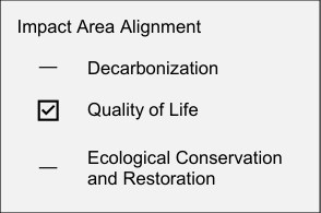
Indoor Environmental Quality Prerequisite
FUNDAMENTAL AIR QUALITY
EQp2
REQUIRED
INTENT
To design for above-average indoor air quality (IAQ) to support occupant health and well-being.
REQUIREMENTS
| Achievement pathways | Points |
|---|---|
Commercial Interiors | N/A |
Investigate Regional and Local Air Quality | |
AND | AND |
Ventilation and Filtration Design | Ventilation and Filtration Design |
AND | AND |
Entryway System Designs | Entryway System Designs |
Comply with the following requirements:
Investigate Regional and Local Air Quality
Investigate outdoor air quality in accordance with ASHRAE Standard 62.1-2022, Sections 4.1– 4.3.
AND
Ventilation and Filtration Design
Meet the requirements of ASHRAE Standard 62.1-2022, S ections 5 and 6. Use the ventilation rate procedure, the IAQ procedure, the natural ventilation procedure, or a combination thereof. Comply with the following additional provisions:
Filtration Each central HVAC system within the project’s scope of work that supplies outdoor air and/or recirculated air to regularly occupied spaces must meet one of the following:
-
Minimum efficiency reporting value of 13, in accordance with ASHRAE Standard 52.2-2017 ; OR
-
Equivalent filtration media class of ePM1 50%, as defined by ISO 16890-2016, “Particulate Air Filters for General Ventilation — Determination of the Filtration Performance.”
U.S. Green Building Council LEED v5 Reference Guide for Interior Design and Construction, April 2025 Launch Edition 297
PDF Page 309
- In-room air-cleaning systems.
o Use systems tested for effectiveness and safety per ASHRAE Standard 241-2023,
Section 7.4 and Normative Appendix A. If treating for particles and gases, use systems tested for effectiveness per ASHRAE 62.1-2022, Addendum N. If treating for infectious aerosols, use systems tested for effectiveness per ASHRAE Standard 241-2023, Section 7.
Outdoor air measurement Provide outdoor airflow measurement devices for all mechanical ventilation systems in the project scope of work with outdoor air intake flow greater than 1,000 cfm (472 L/s).
Healthcare
- For healthcare spaces, meet the requirements of Sections 6–10 of ASHRAE Standard 170-2021 as applicable.
AND
Entryway System Designs
Install permanent entryway systems to capture dirt and particulates entering the building at primary exterior entrances within the project scope of work. There is no length requirement for entryway systems.
REQUIREMENTS EXPLAINED
This prerequisite requires the project team to research regional and local air quality and provide ventilation systems and design elements that effectively support air quality within the building. Healthcare and residential projects have additional considerations.
Investigate Regional and Local Air Quality
IAQ is significantly influenced by outdoor air quality, which can be highly localized, varying over time, season, and throughout the project site.
To understand outdoor air quality for the project, regional air quality and local air quality must be investigated, considering seasonal variations. ASHRAE 62.1 [112] provides a template for documenting this investigation. In many regions, spring months have higher pollen levels from flowering plants and trees. Summer months in some dry, hot regions have higher levels of PM2.5 due to wildfires and ozone from photochemical smog. Air quality for the project’s location
112 “ASHRAE 62.1”, ASHRAE, accessed March 31, 2025, https://www.ashrae.org/technical-resources/bookstore/standards-62-1-622.
U.S. Green Building Council LEED v5 Reference Guide for Interior Design and Construction, April 2025 Launch Edition 298
PDF Page 310
will likely change over time, due to climate change. For example, the periods with higher pollen levels and wildfires may increase or intensify. For this reason, information collected during the IPp1: Climate Resilience Assessment should be included in this investigation.
REGIONAL AIR QUALITY
Regional air quality is partially determined by reviewing compliance with national ambient air quality standards. In the U.S., air quality monitoring data is available to determine the region’s status relative to acceptable levels for six regional outdoor air quality pollutants (particulate matter, carbon monoxide, ozone, nitrogen dioxide, lead, sulfur dioxide).
LOCAL AIR QUALITY
Local air quality is typically determined through observations by walking around the project site and reviewing the neighborhood context. Examples of items to survey include facilities on-site and on adjacent properties, description of sources of vehicle exhaust on-site and adjacent properties, and identification of potential contaminant sources on the site and from adjoining properties. Most of this information will be gathered in the IPp2: Human Impact Assessment.
The results of the outdoor air quality investigation inform the design of critical elements of the mechanical system, including the air intake locations on the building, the filtration levels used, or the use of air-cleaning devices. The investigation also helps determine exhaust and equipment locations to minimize impacts to neighboring buildings or building occupants.
Ventilation and Filtration
ASHRAE Standard 62.1-2022 is the referenced ventilation standard for most commercial buildings. The Standard establishes minimum ventilation requirements and other measures for IAQ that is acceptable to human occupants and that minimizes adverse health effects.
The standard involves designing for IAQ using one of three available procedures: the ventilation rate procedure (VRP), indoor air quality procedure (IAQP), or the natural ventilation procedure (NVP). Any combination of options may be used for compliance with this prerequisite.
IAQP VERIFICATION
If the IAQP is used to comply with this prerequisite, an extra verification step after building completion is required that involves air quality testing and conducting a subjective occupant evaluation. These verification steps are outlined in ASHRAE 62.1-2022, Section 7.3 IAQP Verification.
U.S. Green Building Council LEED v5 Reference Guide for Interior Design and Construction, April 2025 Launch Edition 299
PDF Page 311
FILTRATION
This prerequisite has additional filtration requirements beyond those in ASHRAE 62.1 . MERV 13 filtration (and ePM1 50%) is becoming standard practice, and most HVAC systems can be designed to easily accommodate this level of filtration. The filtration requirements apply to all central HVAC systems that supply outdoor air, recirculated air, or outdoor air and recirculated air to regularly occupied spaces. Projects that use base building ventilation systems will need to confirm that those systems comply.
MERV 13 filtration is not required for systems that supply air to warehouses or other areas addressed in the ASHRAE exemption for outdoor air treatment
Exemption to 6.1.4 Systems supplying air for enclosed parking garages, warehouses, storage rooms, janitor’s closets, trash rooms, recycling areas, and shipping/receiving/distribution areas are exempt.
An alternative approach that allows in-room air cleaning systems to be used offers flexibility in meeting this prerequisite requirement for situations where design constraints make the central system-level filtration requirement infeasible or impractical.
AIR CLEANING SYSTEMS
Air cleaning systems may be used in the design to meet the prerequisite requirements. Before selecting the air cleaning system, ensure the manufacturer has a safety testing report and manufacturer certification that the product is safe. Verified effectiveness values also provided by the manufacturer must be used in the design calculations as applicable.
-
Safety . All air cleaning systems require safety testing according to ASHRAE Standard 241-2023, Section 7.4 and Normative Appendix A. This standard has the most up-todate language to assess safety, which includes addressing chemical emissions and some potential byproducts, ultraviolet radiation, combustion byproducts, and noise generated during operation. Testing is conducted in a specialized test chamber with specific environmental controls. [113]
-
Effectiveness for particle filtration efficiency or gaseous removal efficiency . For systems that treat particles and gases, use only systems that have a verified effectiveness determined according to ASHRAE Standard 62.1-2022, Addendum N.
-
Effectiveness for infectious aerosols . For systems being selected to treat infectious aerosols and meet the minimum equivalent clean airflow rates outlined in ASHRAE
113 “Control of Infectious Aerosols”, ASHRAE, (2023), accessed March 31, 2025, https://www.ashrae.org/file%20library/technical%20resources/standards%20and%20guidelines/standards%20addenda/241_2023_a _20241021.pdf.
U.S. Green Building Council LEED v5 Reference Guide for Interior Design and Construction, April 2025 Launch Edition 300
PDF Page 312
241-2023, Section 5.1 for compliance with the Resilient Spaces credit Option 2 — Management Mode for Respiratory Diseases treat infectious aerosols, use only systems that have a verified effectiveness according to ASHRAE Standard 241-2023, Section 7.
OUTDOOR AIR MEASUREMENT
With proper outdoor airflow monitoring, facility managers can identify ventilation issues and correct problems before they impact IAQ . This credit requires airflow monitoring for larger systems within the project scope of work (more than 1,000 cfm (472 L/s) of outside air). Airflow monitoring is encouraged for smaller systems but not required.
Specific alarm and system control capabilities are not addressed in this prerequisite and may be designed to suit the project’s specific needs.
Healthcare Projects and Spaces
- Healthcare projects must comply with ASHRAE Standard 170-2021 for ventilation design and filtration requirements. ASHRAE 170, Table 7-1 specifies the minimum outdoor air changes per hour (ACH) and minimum total ACH for each healthcare space type. Both requirements must be met. For space types not covered in Standard 170, use ASHRAE Standard 62.1-2022 .
Entryway Systems
Permanent entryway systems prevent dirt and particulates from entering the building. The entryway system requirement for this prerequisite is intentionally broad to accommodate more project situations and to ensure feasibility as a prerequisite requirement.
Acceptable entryway systems include permanently installed grates, grilles, slotted systems that allow for cleaning underneath, or rollout mats.
Entryway systems are required at all primary exterior entrances within the LEED project scope of work .
PRIMARY VS. NONPRIMARY ENTRANCES Primary exterior entrances are the main designated entry points to the building. These entrances typically have the most visibility and accessibility. Design elements, like canopies or biophilic elements, often attract entry.
Nonprimary entrances are less visible and often have limited access or are used less frequently. A nonprimary entrance includes service access points or lift lobbies, side or
U.S. Green Building Council LEED v5 Reference Guide for Interior Design and Construction, April 2025 Launch Edition 301
PDF Page 313
back doors, garage/parking level entries, emergency exits, connections between concourses, and atrium entries.
While the prerequisite only requires entryway systems at primary exterior entrances within the LEED project scope of work, projects may benefit from installing entryway systems at all exterior entrances of the building.
ENTRYWAY SYSTEM LENGTH AND DESIGN There are no length requirements for the entryway systems, but it is highly recommended to utilize the best practice length of at least 10 feet (3 m.) in the primary direction of travel, which allows for approximately two full steps per shoe from an average person.
Design the entryway system to accommodate and withstand specific climate conditions. Areas with high precipitation, for example, may need more absorbent mats made with mold- and mildew-resistant materials. If using rollout mats, consider selecting ones that have a solid backing. A nonporous backing captures dirt and moisture and helps prevent contaminants from collecting underneath the mat.
Regular cleaning and maintenance will extend the integrity of the entryway system. Projects are encouraged to provide routine care for these systems, which is typically weekly.
DOCUMENTATION
| Project types | Options | Paths | Documentation |
|---|---|---|---|
All | All | All | Results of regional and local air quality investigation, at minimum, date and time of observations, a description of the site, observed odors or irritants, and conclusions regarding acceptability of the outdoor air quality. |
All | All | All | Indication of whether the building is in an area where the national guideline is exceeded (outdoor air treatment is required per_ASHRAE_ 62.1-2022, Section 6.1.4). |
All | All | All | Calculation documents for mechanical VRP, NVP and IAQP. |
All | All | All | Air cleaning systems (if used): supporting documentation for safety and effectiveness. |
All | All | All | IAQ Procedure: Air Quality Test Plan and Occupant Survey Methodology |
All | All | All | IAQP: Completed air quality testing report including time, date, testing methods complying with credit requirements, results and limits of the tested contaminants in all locations, and lab accreditation scope for VOCs. |
All | All | All | IAQ Procedure: Subjective Occupant Evaluation Results. |
U.S. Green Building Council LEED v5 Reference Guide for Interior Design and Construction, April 2025 Launch Edition 302
PDF Page 314
| Project types | Options | Paths | Documentation |
|---|---|---|---|
| Floor plans or photos of entryway systems. | |||
| Design documents confirming filter grade and implementation. | |||
| Control diagrams showing outdoor air measurement devices (where required). | |||
Confirmation the outdoor air measurement devices measures airflow rates. |
REFERENCED STANDARDS
- ASHRAE standard 170-2021 (ashrae.org/technical-resources/standards-and- guidelines/standards-addenda/ansi-ashrae-ashe-standard-170-2017-ventilation-of-health- care-facilities)
U.S. Green Building Council LEED v5 Reference Guide for Interior Design and Construction, April 2025 Launch Edition 303
PDF Page 315
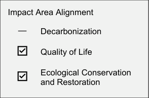
Indoor Environmental Quality Prerequisite
NO SMOKING
EQp3
REQUIRED
INTENT
To minimize exposure to tobacco smoke, smoke from tobacco substitutes or cannabis, and vehicle emissions.
REQUIREMENTS
| Achievement pathways | Points |
|---|---|
Commercial Interiors | N/A |
Option 1. Locations With Smoking Prohibitions | |
OR | OR |
Option 2. Projects Located in Buildings Where Smoking Is Not Prohibited by Law | Option 2. Projects Located in Buildings Where Smoking Is Not Prohibited by Law |
Option 1. Buildings with Full Smoking Prohibitions
Locate the project in a building in which smoking inside the building is prohibited by law or by the landlord, and the no-smoking policy is communicated to all building occupants according to the law or with permanently installed signage.
Prohibit smoking outside the project, except in designated smoking areas located at least 25 feet (7.5 meters), or the maximum extent allowable by local codes, from all exterior entries, outdoor air intakes, and operable windows to the project.
OR
Option 2. Buildings with Partial Smoking Prohibitions
Prohibit smoking in the project spaces.
Smoking must also be prohibited in all common areas used by the project occupants and any areas of the building served by the same HVAC system as the project. Ensure that smoke cannot migrate by either mechanical or natural ventilation into the project spaces.
Communicate the no-smoking policy to occupants of the project. Have in place provisions for enforcement or no-smoking signage.
U.S. Green Building Council LEED v5 Reference Guide for Interior Design and Construction, April 2025 Launch Edition 304
PDF Page 316
REQUIREMENTS EXPLAINED
This prerequisite requires locating the project in a building with smoking restrictions and prohibiting smoking inside the project spaces and near building openings.
Smoke-free policies effectively reduce tobacco use, protect people from secondhand smoke exposure, prevent tobacco-related illnesses and deaths, and help more people successfully quit smoking.
Smoking is prohibited for conventional cigarettes (cigarettes, cigars, pipes), cannabis (medical or recreational), and electronic smoking devices (e-cigarettes). The intent is to keep the air inside the building free from pollutants and contaminants associated with smoking.
Exclusions This prerequisite is not intended to prohibit or deter indigenous or other cultural ceremonial practices (e.g., smudging) which may include the combustion of tobacco and other ceremonial materials. LEED projects that accommodate cultural ceremonial practices may still pursue this prerequisite.
Option 1. Locations with Smoking Prohibitions
INDOOR SMOKING
Smoking must be strictly prohibited inside the building at all times. Evidence of this prohibition can be obtained via a policy from the owner, facility manager, or smoke-free indoor air law.
OUTDOOR SMOKING
Smoking must be prohibited on the project site except in areas specifically designated for smoking. No smoking is permitted within 25 feet (7.5 meters) of all building openings, such as doors, windows, and ventilation intakes, to minimize the likelihood of smoke entering the building. Exterior spaces used by any tenants in the building must be no-smoking. For example, if the LEED project occupies second-floor space in a building with multiple tenants, smoking is not allowed within 25 feet (7.5 meters) of any opening for the entire building.
Emergency exits do not qualify as building openings if the doors are alarmed, as alarmed doors will rarely be opened. Emergency exits without alarms qualify as building openings.
Smoking is not allowed in programmable spaces (e.g., outdoor cigar lounges or casino areas, courtyards, outdoor cafes or sidewalk seating, or space used for business purposes).
U.S. Green Building Council LEED v5 Reference Guide for Interior Design and Construction, April 2025 Launch Edition 305
PDF Page 317
A designated smoking area is a specific outdoor location where smoking is permitted. This can be an unenclosed pavilion with safe disposal bins for cigarettes. Business cannot be conducted in this area, but design strategies to make people feel comfortable, such as covered seating, are encouraged.
NO-SMOKING SIGNAGE
The project determines the placement and design of signage, allowing for flexibility to address site-specific considerations and to accommodate existing signage that may already be in place.
When communicating a no-smoking policy, use signage that includes illustrations, photographs, or clear and concise wording. Consider using explicit language such as “No smoking allowed within xx feet” or “Smoking is allowed in designated smoking areas only.” Signs should clearly indicate the designated smoking areas.
Option 2. Projects Located in Buildings Where Smoking is not Prohibited by Law
This option is available for projects located in areas without no- smoking laws to accommodate situations where the project owner has limited control to prohibit smoking activities in another tenant’s spaces or in cases where the project owner is unable to acquire necessary documentation to confirm compliance with Option 1. Prohibiting indoor smoking is the only way to fully eliminate the health risks associated with smoking. When possible, Commercial Interior projects should work with the building owner to develop policies compliant with Option 1.
INDOOR SMOKING
Smoking must be strictly prohibited inside the project spaces at all times. Evidence of this prohibition can be obtained via a policy from the owner or facility manager or smokefree indoor air law.
The building must also have in place a policy to prohibit smoking in all common areas such as lobbies, corridors, and other communal spaces and any areas of the building served by the same HVAC system as the project. Teams should consider implementing ventilation barriers or pressurization techniques to prevent smoke migrations between spaces. Projects should ensure proper air-sealing to prevent smoke migration through natural ventilation paths.
U.S. Green Building Council LEED v5 Reference Guide for Interior Design and Construction, April 2025 Launch Edition 306
PDF Page 318
DOCUMENTATION
| Project types | Options | Paths | Documentation |
|---|---|---|---|
All | Both | All | Confirmation of project scope (the project includes/does not include any exterior entries, outdoor air intakes within 25 ft. (7.5 m.) of an occupant-accessible area (such as roof, sidewalk, balcony), operable windows, designated smoking areas, a dedicated HVAC system; the project is/is not located in a building that prohibits smoking inside the whole building by landlord and/or law). |
All | Option 1. Buildings with Full Smoking Prohibitio ns | All | If applicable, documents identifying the location of building entries, alarmed emergency exits, outdoor air intakes, operable windows, designated smoking areas, signage communicating the indoor and outdoor smoking and vehicle idling prohibitions to occupants, signage key/schedule. |
All | Option 1. Buildings with Full Smoking Prohibitio ns | All | Excerpt of project’s no-smoking policy or indication of smokefree indoor air law. |
All | Option 1. Buildings with Full Smoking Prohibitio ns | All | If not documented by law excerpt, evidence that the base building indoor no-smoking policy is communicated to all building occupants with permanently installed signage (for example, photographs with date/time/location stamp and a key plan documenting all smoking prohibition signage installed by landlord). |
All | Option 1. Buildings with Full Smoking Prohibitio ns | All | Documents identifying the location of building entries, alarmed emergency exits, outdoor air intakes, operable windows, designated smoking areas, signage communicating the indoor and outdoor smoking prohibitions to occupants, signage key/schedule. |
All | Option 2. Projects With Partial Smoking Prohibitio ns | All | Excerpt of project’s no-smoking policy or indication of smokefree indoor air law. |
All | Option 2. Projects With Partial Smoking Prohibitio ns | All | Evidence that smoking is prohibited in all common areas used by the project occupants (for example, photographs with date/time/location stamp documenting signage posted by the landlord in all common areas used by the project occupants). |
All | Option 2. Projects With Partial Smoking Prohibitio ns | All | Evidence that ETS cannot migrate by natural ventilation into the project spaces. |
REFERENCED STANDARDS
- None
U.S. Green Building Council LEED v5 Reference Guide for Interior Design and Construction, April 2025 Launch Edition 307
PDF Page 319
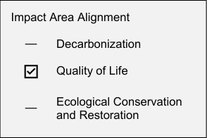
Indoor Environmental Quality Credit
ENHANCED AIR QUALITY
EQc1
1–2 points
INTENT
To design for increased indoor air quality (IAQ) to better protect the health of building occupants.
REQUIREMENTS
| Achievement pathways | Points |
|---|---|
Commercial Interiors | 1–2 |
Option 1. Increased Ventilation | 2 |
OR | |
Option 2. Enhanced Indoor Air Quality Design | 1 |
OR | |
Option 3. Verification of Ventilation and Filtration | 1 |
Design the project to exceed the requirements of ASHRAE 62.1-2022, Section 6. If using the ventilation rate procedure to comply with EQp2: Fundamental Air Quality, use Option 1 or Option 2; if using the indoor air quality procedure (IAQP), use Option 2.
Option 1. Increased Ventilation (2 points)
Increase breathing zone outdoor air ventilation rates by at least 15% above the minimum rates (for 1 point, or 30% for 2 points) as determined in EQp2: Fundamental Air Quality .
Increased outdoor air rates should be provided to 95% of all regularly occupied spaces.
OR
Option 2. Enhanced Indoor Air Quality Design (1 point)
In addition to the design compounds and design limits outlined in ASHRAE 62.1-2022, Tables 65 and 6-6, design and verify enhanced IAQ using the lower design limits listed below in Table 1.
Table 1. Additional design limits for enhanced IA Q design
| Design compound or PM2.5 | Enhanced IAQP design limit* |
|---|---|
PM2.5 | 10 ug/m3 |
Formaldehyde | 20 µg/m³ |
Ozone | 10 ppb |
U.S. Green Building Council LEED v5 Reference Guide for Interior Design and Construction, April 2025 Launch Edition 308
PDF Page 320
OR
Option 3. Verification of Ventilation and Filtration (1 point)
For spaces receiving mechanical ventilation from base building systems, measure the total quantity of outdoor air delivered to the project and verify the results are within 10% of the rates reported in EQp2: Fundamental Air Quality, and outlined in the current facilities requirements and operations and maintenance plan. Measurements shall quantify the amount of outdoor air for each base building air-handling unit serving the project, and account for worst-case conditions.
NOT E: This path is only applicable for tenant improvements to a previously occupied space and is not applicable for initial build-out.
REQUIREMENTS EXPLAINED
The credit incentivizes designing systems that continuously provide enhanced air quality during building occupancy. For measures that provide enhanced air quality only in specific circumstances, refer to EQc4: Resilient Spaces for more guidance .
Both options in this credit utilize measures described in ASHRAE Guideline 42-2023, Enhanced IAQ in Commercial and Institutional Buildings [114], with the goal of providing enhanced IAQ. Projects are encouraged to address additional measures from ASHRAE Guideline 42 beyond those included in this credit.
NOTE: If the VRP is being used for EQp2 Fundamental Air Quality, it is expected Option 1 for this credit will be used. However, it is not required. Review both options and choose the one that most aligns with your project goals for enhanced air quality.
Option 1. Increased Ventilation
Providing additional outdoor airflow, above the minimum requirements for ventilation and building pressurization, can further dilute and reduce indoor air pollutants. Research has shown increased ventilation may improve cognitive performance and associated productivity and income, reduce absenteeism in commercial offices115, and improve sleep quality in residential applications. [116]
114 “ASHRAE Guideline 42-2023, Enhanced IAQ in Commercial and Industrial Buildings”, ASHRAE, accessed March 31, 2025, https://webstore.ansi.org/standards/ashrae/ashraeguideline422023?srsltid=AfmBOopTadTVeaxVchSAjaJzniAV9cO8JOiwPzY3gJKpThsXYn_SxOQ. 115 Licina, D., Wargocki, P. et al. “The future of IEQ in green building certifications”, (2021), Buildings and Cities, 2(1), pp. 907–927, DOI: https://doi.org/10.5334/bc.148. 116 Wargocki, P., Akimoto, M. et al. “Ventilation and sleep quality”, AIVC, (2023), accessed March 31, 2025, https://www.aivc.org/resource/ventilation-and-sleep-quality.
U.S. Green Building Council LEED v5 Reference Guide for Interior Design and Construction, April 2025 Launch Edition 309
PDF Page 321
INCREASED VENTILATION THRESHOLDS
Projects must demonstrate a 15% increase in outdoor airflow rates over the minimum requirements of ASHRAE Standard 62.1-2022 . Most large HVAC systems can accommodate a 15% increase with minimal impacts to the design and to energy consumption. An alternative threshold of 30% is available through exemplary performance.
REGULARLY OCCUPIED SPACES REQUIREMENT
At least 95% of all regularly occupied spaces must have increased ventilation. This provides flexibility for projects that cannot meet the higher thresholds in every space.
DETERMINING THE INCREASED VENTILATION REQUIREMENT
The following VRP calculations determine the increased ventilation requirement:
-
Single-zone or 100% outdoor air system . Multiply the calculated minimum outdoor air flow for the system (Vot) by 1.15.
-
Multiple-zone recirculating system . Multiply the uncorrected outdoor air flow for the system (Vou) by 1.15. Multiply the breathing zone outdoor airflow for the critical zone (Vbz for critical zone) by 1.15. Calculate the new system ventilation efficiency (Ev) using the updated values for Vou and the critical zone Vbz and recalculate the required outdoor air intake flow for the system (Vot) using these values.
Option 2. Enhanced IAQ Design
The option requires using more stringent design limits for ozone, formaldehyde and PM2.5 to achieve enhanced levels of IAQ beyond EQp2: Fundamental Air Quality. This credit uses LEEDspecific design targets, selected by the LEED indoor EQ technical advisory group, with the following basis:
OZONE
A design target of 10 ppb was selected as referenced in the Environmental Health Committee (EHC) Emerging Issue Report [117] . This number reflects the thinking that ozone indoors is harmful and the lower the concentration, the better. Studies indicate that any “safe” threshold would exist at very low concentrations.
117 “Emerging issue: Ozone and indoor air chemistry”, ASHRAE, (2011), accessed March 31, 2025, https://ashrae.org/file%20library/communities/committees/standing%20committees/environmental%20health%20committee%20(ehc )/ehc_emerging_issue-ozoneandindoorairchemistry.pdf.
U.S. Green Building Council LEED v5 Reference Guide for Interior Design and Construction, April 2025 Launch Edition 310
PDF Page 322
FORMALDEHYDE
A design target of 20 µg/m³ (16 ppb) was selected based on the NIOSH recommended airborne exposure limit (REL ) and FEMA goal for emergency housing [118] . Formaldehyde is a carcinogen that can irritate the skin and eyes. Long-term exposure has been associated with increased allergic sensitivity and asthma. Many building products contain formaldehyde as addressed in the MRc Low-Emitting Material s.
PM2.5 A design target of 10 ug/m3 was selected based on the WHO global air quality guidelines, PM2.5 interim target 4. [119] This number reflects the thinking that adverse effects from PM2.5 can occur at low concentrations approaching zero, so PM2.5 should be maintained as low as reasonably achievable in interior spaces.
If air cleaning systems are used to achieve the enhanced IAQ design targets, refer to the guidance on air cleaning devices in EQp2: Fundamental Air Quality .
Option 3. Verification of Ventilation and Filtration
When planning a new build-out in an existing building, it is critical to understand the base building systems and their capability to provide ventilation for the planned occupancy. Option 3 requires the project team to measure and verify the total quantity of outdoor air delivered to the tenant space from the existing base building HVAC systems.
MEASUREMENT AND REPORTING REQUIREMENTS
Measurements from calibrated airflow measuring stations or an approved test, adjust, and balance report from the contractor may be used.
Measure the outdoor airflow to the project from each base building air-handling unit that serves spaces within the LEED project scope. Acceptable measurements may come from calibrated airflow measuring stations or contractor test, adjust, and balancing reports. Take measurements under worst-case operating conditions.
Confirm that the results for each air handling unit are within 10% of the minimum outdoor airflow value determined for EQp2: Fundamental Air Quality .
This path is only available to projects that renovate previously occupied spaces.
118 “Formaldehyde”, Chemical Insights, accessed March 31, 2025, https://chemicalinsights.org/wpcontent/uploads/FactSheet_Formaldehyde.pdf. 119 “WHO global air quality guidelines. Particulate matter (PM2.5 and PM10), ozone, nitrogen dioxide, sulfer dioxide”, Geneva: World Health Organization, (2021), https://iris.who.int/bitstream/handle/10665/345329/9789240034228-eng.pdf.
U.S. Green Building Council LEED v5 Reference Guide for Interior Design and Construction, April 2025 Launch Edition 311
PDF Page 323
DOCUMENTATION
| Project types | Options | Paths | Documentation |
|---|---|---|---|
All | Option 1. Increased Ventilation | Alll | Calculations documented under the fundamental air quality prerequisite. |
All | Option 2. Enhanced IAQ Design | Option 2. Enhanced IAQ Design | Documentation provided under the fundamental air quality prerequisite. |
All | Option 3. Verification of Ventilation and Filtration | Option 3. Verification of Ventilation and Filtration | Method or protocol used to measure the amount of outdoor air delivered by each ventilation system and measured outdoor rates. |
REFERENCED STANDARDS
U.S. Green Building Council LEED v5 Reference Guide for Interior Design and Construction, April 2025 Launch Edition 312
PDF Page 324
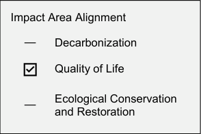
Indoor Environmental Quality Credit
OCCUPANT EXPERIENCE
EQc2
1–7 points
INTENT
To move beyond neutral or sufficient spaces toward human-centered design that supports customization, enjoyment, and emotional connections between people and the building, thus increasing the likelihood of consistent satisfaction and ongoing stewardship.
REQUIREMENTS
| Achievement pathways | Points |
|---|---|
Commercial Interiors | 1–7 |
Option 1. Biophilic Environment | 1–4 |
Path 1. Integrated Biophilic Design | 1 |
AND/OR | |
Path 2. Quality Views | 2–3 |
AND/OR | |
Option 2. Adaptable Environment | 1–2 |
AND/OR | |
Option 3. Thermal Environment | 1 |
AND/OR | |
Option 4. Sound Environment | 1–2 |
Path 1. Mapping Acoustical Expectations for Indoor and Outdoor Spaces | 1 |
AND/OR | |
Path 2. Acoustic Criteria for Indoor and Outdoor Spaces | 1 |
AND/OR | |
Option 5. Lighting Environment | 1–6 |
Path 1. Solar Glare | 1 |
AND/OR | |
Path 2. Quality Electric Lighting | 1 |
AND/OR | |
Path 3. Proximity to Windows for Daylight Access | 1 |
AND/OR | |
Path 4. Daylight Simulation | 1–4 |
Option 1. Biophilic Environment (1–4 points)
PATH 1. INTEGRATED BIOPHILIC DESIGN (1 POINT)
Integrate biophilic design that demonstrates each of the following five principles adapted from The Practice of Biophilic Design by Kellert and Calabrese [120] :
120 Kellert, S. and Calabrese, E. The Practice of Biophilic Design, (2015), https://www.biophilic-design.com.
U.S. Green Building Council LEED v5 Reference Guide for Interior Design and Construction, April 2025 Launch Edition 313
PDF Page 325
-
Biophilic design requires repeated and sustained engagement with nature.
-
Biophilic design focuses on human adaptations to the natural world that, over evolutionary time, have advanced people’s health, fitness, and well-being.
-
Biophilic design encourages an emotional attachment to the building and building location.
-
Biophilic design promotes positive interactions between people and nature that encourage an expanded sense of relationship and responsibility for the human and natural communities.
-
Biophilic design encourages mutual reinforcing, interconnected, and integrated architectural solutions.
-
AND/OR
PATH 2. QUALITY VIEWS (2–3 POINTS)
Provide occupants in the building with a view to the outdoor natural or urban environment for 75% (for 2 points, 90% for 3 points) of all regularly occupied floor area. Auditoriums, conference rooms dedicated to video conferencing, and gymnasiums may be excluded. Views into interior atria may be used to meet up to 30% of the required area.
-
Views must be through glass with a visible light transmittance above 40%. If the glazing has frits, patterns, or tints, the view must be preserved. Neutral gray, bronze, and bluegreen tints are acceptable.
-
Views must include at least one of the following.
o Nature, urban landmarks, or art; OR
o Objects at least 25 feet (7.5 meters) from the exterior of the glazing.
- Occupants must have direct access to the view and be within three times the head height of the glazing.
AND/OR
Option 2. Adaptable Environment (1–2 points)
Allow occupants choice and flexibility, and/or the capability to adapt the space to meet their individual needs. Provide variability and/or optionality for thermal, sound, and lighting environments that invite occupants to either alter their experience and/or move between sensory zones. Include at least one accessible quiet space that allows occupants to retreat from high levels of sensory stimulation.
Projects must also demonstrate at least one of the additional strategies below for 1 point or three for 2 points:
U.S. Green Building Council LEED v5 Reference Guide for Interior Design and Construction, April 2025 Launch Edition 314
PDF Page 326
Additional strategies
-
Provide socializing, meeting, dining, eating, and/or working areas where occupants can sit outside the main action and have permanent architectural features at their backs, creating a comfortable, semiprotected space that overlooks the larger area (prospect).
-
Provide alternative paths that enable travel around the perimeter of the space, so that people are not required to travel across a large open space.
-
Provide choice in furniture configuration and a variety of seating to accommodate a wide range of body types, including seating with back rests and without arm rests.
-
Provide height variety for permanently installed fixtures, like counters and sinks, and/or height-adjustable tables and desks, where appropriate.
-
Provide the ability for all occupants to easily access outdoor or transitional space located within 2,000 feet (600 meters) of a building entrance or access point.
AND/OR
Option 3. Thermal Environment (1 point)
-
Design indoor occupied spaces to meet the requirements of ASHRAE Standard 55-2023, “Thermal Environmental Conditions for Human Occupancy” with errata. Investigate thermal conditions in and around the project and explain how the design considers the following:
- Thermal conditions that align and adjust with changing seasons
-
Overcooling during nontemperate seasons
o Design solutions for newly arrived occupants or occupants transitioning between
different thermal environments to adjust to the space while maintaining an appropriately warm environment for those already in the building.
o Design solutions for long-term occupants in transition spaces to customize their
working area.
- Support for occupants carrying out different tasks requiring varying levels of movement
o Cooling solutions for those completing high-movement tasks
AND/OR
Option 4. Sound Environment (1–2 points)
PATH 1. MAPPING ACOUSTICAL EXPECTATIONS FOR INDOOR AND OUTDOOR SPACES (1 POINT)
Determine the desired sound environment early in the design process by mapping the acoustical expectations for each primary indoor and outdoor space, specific to the use of the space and occupant needs. Categories to consider include noise exposure, acoustical comfort and noise sensitivity, acoustical privacy, communication, and soundscape.
These are example classifications for:
U.S. Green Building Council LEED v5 Reference Guide for Interior Design and Construction, April 2025 Launch Edition 315
PDF Page 327
o Noise exposure zones : high risk, medium risk, low risk, or no risk.
o Acoustical comfort : loud zone, quiet zone, mixed zone, circulation, sensitive, and
no specific expectations.
o Acoustical privacy : high speech security, confidential speech privacy, normal
speech privacy, marginal speech privacy, or no privacy.
o Communication zones : excellent, good, marginal, and none or no specific
expectations.
o Soundscape management : preserve, improve, restore, mitigate, specialized (e.g.,
wellness, therapeutic, or agency in equity), or no specific expectations.
Define acoustic criteria and potential design strategies and solutions to meet the acoustical expectations for each space. Categories to consider include internally generated background noise, externally intrusive background noise, electronically generated masking sound, outdoor acoustical environment, airborne sound reverberation, sound insulation, vibration insulation, and impact noise.
OR
PATH 2. ACOUSTIC CRITERIA FOR INDOOR AND OUTDOOR SPACES (2 POINTS)
Through calculations, modeling, and/or measurements, demonstrate that the mapping exercise completed in Path 1 informed design strategies and solutions to meet acoustic criteria for at least 75% of the occupied spaces and all classrooms and other core learning spaces.
AND/OR
Option 5. Lighting Environment (1–6 points)
PATH 1. SOLAR GLARE (1 POINT)
Provide manual or automatic (with manual override) glare-control devices in all regularly occupied spaces that will receive direct or reflected sun penetration. Spaces designed intentionally for direct sunlight may be excluded.
AND/OR
PATH 2. QUALITY ELECTRIC LIGHTING (1 POINT)
Comply with the following requirements for regularly occupied spaces:
Electric light glare control Each luminaire shall meet one of the following requirements:
- Have calculated luminance of less than 6,000 candela per square meter (cd/sq. m.) between 45 and 90 degrees from nadir.
U.S. Green Building Council LEED v5 Reference Guide for Interior Design and Construction, April 2025 Launch Edition 316
PDF Page 328
-
Achieve a unified glare rating (UGR) of 19 or lower using the UGR tabular method for each space.
- Achieve a UGR rating of 19 or lower using software modeling calculations of the designed lighting. (Modeling must be performed as outlined in the NEMA White Paper on Unified Glare Rating [121] .)
Color rendering Use luminaires that have a color rendering index of at least 90, or that meet the color rendering requirements in Table 1, in accordance with Illuminating Engineering Society (IES) TM-30-20.
Table 1. Color rendering requirements using TM-30-20
| Measure | Col2 | Requirement |
|---|---|---|
Fidelity index | Rf | 78 or higher |
Gamut index | Rg | 95 or higher |
Red Local Chroma Shift | Rcs,h1 | -1% to 15% |
AND/OR
PATH 3. PROXIMITY TO WINDOWS FOR DAYLIGHT ACCESS (1 POINT)
Design the interior layout to provide at least 30% of the regularly occupied area to be within a 20-foot (6 meters) horizontal distance of envelope glazing. The glazing must have a visible light transmittance above 40%. Regularly occupied areas with visual obstructions (incapable of providing a view to envelope glazing) should be excluded from the compliant area.
OR
PATH 4. DAYLIGHT SIMULATION (1–4 POINTS)
Perform a daylight simulation analysis for the project to understand and optimize access to daylight and visual comfort. Use the calculation protocols in IES LM-83-23 with the following clarifications:
-
Calculate s patial daylight autonomy300/50% (sDA300/50%) and annual sunlight exposure1000,250 (ASE1000,250) as defined in IES LM-83-23 for each regularly occupied space in the project. sDA 150/50% may be used for areas without visual tasks with design targets of 225 lux.
-
For any regularly occupied spaces with ASEnet(1000,250h) greater than 20%, identify how the space is designed to address glare.
-
Calculate the average sDA 300/50% or sDA 150/50% for the total regularly occupied floor area. Do not exclude spaces based on ASE. Points are awarded based on this calculation, according to Table 2.
121 “NEMA White Paper on Unified Glare Rating”, NEMA, (2021), accessed March 21, 2025, https://www.nema.org/standards/view/white-paper-on-unified-glare-rating-(ugr)
U.S. Green Building Council LEED v5 Reference Guide for Interior Design and Construction, April 2025 Launch Edition 317
PDF Page 329
Table 2. Points for d aylight simulation
| Average sDA300/50% or sDA150/50% value | Points |
|---|---|
| ≥ 40% | 1 |
≥ 55% | 2 |
≥ 65% | 3 |
≥ 75% | 4 |
REQUIREMENTS EXPLAINED
This credit promotes spaces that are designed to enhance the occupant experience through multisensory experiences, connections with nature and natural systems, spatial variability and opportunities for personalization, as well as a broader view of thermal, sound, and lighting design. Though there are multiple options to achieve the credit — and strategies — will (and should) look significantly different between projects. All approaches should aid in catalyzing enjoyment and memorability of the space, in turn, increasing the likelihood of sustained satisfaction and ongoing stewardship of the building. [122]
Option 1. Biophilic Environment
PATH 1. INDOOR BIOPHILIC DESIGN
Biophilic design is based on the ethical imperative to promote human and environmental health and well-being by reconnecting people to nature and to each other within the built environment. Incorporating nature, both directly or indirectly, can offer significant benefits to physical, mental, and social health. [123] Biophilic design can also be a tool to improve how we connect with others to enhance a sense of community. [124] Effective biophilic design considers cultural, geographical, and ecological contexts. Refer to IPp2: Human Impact Assessment findings for relevant contextualization .
Strategies must contribute to an integrated experience and should not exist in an individual or fragmented manner. As such, there is no minimum threshold for the number of required biophilic design strategies. Instead, projects must demonstrate compliance with each of the five principles adapted from The Practice of Biophilic Design. [125]
122 DeKay, M., & Brager, G. (2023), Experience Design Schemas: Diagrams for Bioclimatic, Energy, and Resiliency Architecture, Routledge. 123 Catherine O. Ryan, William D. Browning, & Dakota B. Walker (2023), The economics of biophilia: Why designing with nature in mind makes financial sense, Second edition. New York: Terrapin Bright Green, LLC., https://www.terrapinbrightgreen.com/report/eob-2. 124 Heath, O., Jackson, V., & Goode, E. (2019), Creating Positive Spaces by Designing for Community, Interface, Well-being https://www.interface.com/content/dam/interfaceinc/interface/publications/brochures-collateral/emea/design-guides/communitydesign-guide/DesignGuide_community_emea_EN.pdf. 125 Kellert, Stephen R. and Calbrese, Elizabeth F., 2015, The Practice of Biophilic Design, https://www.biophilic-design.com/.
U.S. Green Building Council LEED v5 Reference Guide for Interior Design and Construction, April 2025 Launch Edition 318
PDF Page 330
-
Biophilic design requires repeated and sustained engagement with nature. Projects must incorporate nature or natural patterns or systems, throughout multiple facets of the building.
-
Biophilic design focuses on human adaptations to the natural world that over evolutionary time have advanced people’s health, fitness, and well-being . Complying with this principle requires creating spaces that support fundamental needs of both human and natural communities, including access to daylight and fresh air, connections to nature through views and materials, opportunities for movement and sensory engagement, spaces for both social interaction and quiet refuge, and integration with local ecosystems and natural patterns.
-
Biophilic design encourages an emotional attachment to particular settings and places . Projects must understand, embrace, and celebrate the specific ecology, culture, climate, and/or region of a project so that it is culturally and ecologically responsive and unique.
-
Biophilic design promotes positive interactions between people and nature that encourage an expanded sense of relationship and responsibility for the human and natural communities . Complying with this principle requires design that elicits a positive emotional response, increasing the likelihood of ongoing enjoyment, belonging, and, ultimately, stewardship, of fellow occupants and of the building.
-
Biophilic design encourages mutual reinforcing, interconnected, and integrated architectural solutions . Projects must apply an ecosystem approach to the design process, where the solution is greater than the sum of its parts, and nature and natural systems or processes are holistically integrated directly and indirectly throughout the project.
-
Any biophilic design framework may be used to demonstrate compliance. Other widely respected frameworks include the 14 Patterns of Biophilic Design by Terrapin Bright Green [126] and the Biophilic Design Framework developed by Judith Heerwagen and Gordon H. Orians.
Table 3. Frameworks and strategies for biophilic design
| Frameworks | Strategy Category | Specific Strategy |
|---|---|---|
| 14 Patterns of Biophilic Design (Terrapin Bright Green) | Nature in the space | Visual connection with nature |
| 14 Patterns of Biophilic Design (Terrapin Bright Green) | Nature in the space | Non-visual connection with nature |
| 14 Patterns of Biophilic Design (Terrapin Bright Green) | Nature in the space | Non-rhythmic sensory stimuli |
| 14 Patterns of Biophilic Design (Terrapin Bright Green) | Nature in the space | Thermal and airflow variability |
| 14 Patterns of Biophilic Design (Terrapin Bright Green) | Nature in the space | Presence of water |
| 14 Patterns of Biophilic Design (Terrapin Bright Green) | Nature in the space | Dynamic and diffuse light |
| 14 Patterns of Biophilic Design (Terrapin Bright Green) | Nature in the space | Connection with natural systems |
126 14 Patterns of Biophilic Designs, Terrapin Bright Green, https://www.terrapinbrightgreen.com/reports/14-patterns/
U.S. Green Building Council LEED v5 Reference Guide for Interior Design and Construction, April 2025 Launch Edition 319
PDF Page 331
| Frameworks | Strategy Category | Specific Strategy |
|---|---|---|
| Natural analogues | Biomorphic forms & patterns | |
| Natural analogues | Material connection with nature | |
| Natural analogues | Complexity and order | |
| Nature of the space | Prospect | |
| Nature of the space | Refuge | |
| Nature of the space | Mystery | |
| Nature of the space | Risk/Peril | |
| The Practice of Biophilic Design (Kellert & Calebrese) | Direct experience of nature | Light |
| The Practice of Biophilic Design (Kellert & Calebrese) | Direct experience of nature | Air |
| The Practice of Biophilic Design (Kellert & Calebrese) | Direct experience of nature | Water |
| The Practice of Biophilic Design (Kellert & Calebrese) | Direct experience of nature | Plants |
| The Practice of Biophilic Design (Kellert & Calebrese) | Direct experience of nature | Animals |
| The Practice of Biophilic Design (Kellert & Calebrese) | Direct experience of nature | Weather |
| The Practice of Biophilic Design (Kellert & Calebrese) | Direct experience of nature | Natural landscapes and ecosystems |
| The Practice of Biophilic Design (Kellert & Calebrese) | Direct experience of nature | Fire |
| The Practice of Biophilic Design (Kellert & Calebrese) | Indirect experience of nature | Images of nature |
| The Practice of Biophilic Design (Kellert & Calebrese) | Indirect experience of nature | Natural materials |
| The Practice of Biophilic Design (Kellert & Calebrese) | Indirect experience of nature | Natural colors |
| The Practice of Biophilic Design (Kellert & Calebrese) | Indirect experience of nature | Simulating natural lght and air |
| The Practice of Biophilic Design (Kellert & Calebrese) | Indirect experience of nature | Naturalistic shapes and forms |
| The Practice of Biophilic Design (Kellert & Calebrese) | Indirect experience of nature | Evoking nature |
| The Practice of Biophilic Design (Kellert & Calebrese) | Indirect experience of nature | Information richness |
| The Practice of Biophilic Design (Kellert & Calebrese) | Indirect experience of nature | Age, change, and the patina of time |
| The Practice of Biophilic Design (Kellert & Calebrese) | Indirect experience of nature | Natural geometries |
| The Practice of Biophilic Design (Kellert & Calebrese) | Indirect experience of nature | Biomimicry |
| The Practice of Biophilic Design (Kellert & Calebrese) | Experience of space and place | Prospect and refuge |
| The Practice of Biophilic Design (Kellert & Calebrese) | Experience of space and place | Organized complexity |
| The Practice of Biophilic Design (Kellert & Calebrese) | Experience of space and place | Integration of parts to wholes |
| The Practice of Biophilic Design (Kellert & Calebrese) | Experience of space and place | Transitional spaces |
| The Practice of Biophilic Design (Kellert & Calebrese) | Experience of space and place | Mobility and wayfinding |
| The Practice of Biophilic Design (Kellert & Calebrese) | Experience of space and place | Cultural and ecological attachment to place |
| Biophilic Design Framework (Heerwagen & Orians) | Prospect | Unobstructed views |
| Biophilic Design Framework (Heerwagen & Orians) | Prospect | Visual access to the horizon |
| Biophilic Design Framework (Heerwagen & Orians) | Prospect | Elevated positions |
| Biophilic Design Framework (Heerwagen & Orians) | Refuge | Concealed or protected spaces |
| Biophilic Design Framework (Heerwagen & Orians) | Refuge | Shelter from environmental conditions |
| Biophilic Design Framework (Heerwagen & Orians) | Refuge | Secluded seating areas |
| Biophilic Design Framework (Heerwagen & Orians) | Mystery | Curving paths |
| Biophilic Design Framework (Heerwagen & Orians) | Mystery | Partial views into other spaces |
| Biophilic Design Framework (Heerwagen & Orians) | Mystery | Elements that entice exploration |
| Biophilic Design Framework (Heerwagen & Orians) | Complexity | Diverse textures and patterns |
U.S. Green Building Council LEED v5 Reference Guide for Interior Design and Construction, April 2025 Launch Edition 320
PDF Page 332
| Frameworks | Strategy Category | Specific Strategy |
|---|---|---|
| Richness in visual detail | ||
| Layered views | ||
| Coherence | Logical organization of space | |
| Coherence | Clear pathways | |
| Coherence | Consistent design elements | |
| Change and variability | Seasonal changes | |
| Change and variability | Natural lighting variations | |
| Change and variability | Presence of water | |
| Risk/Peril | Elements that evoke thrill or excitement | |
| Risk/Peril | Overlooks or balconies | |
| Risk/Peril | Stepping stones or bridges | |
| Security and safety | Easily accessible escape routes | |
| Security and safety | Clear lines of sight | |
| Security and safety | Sturdy construction |
PATH 2. QUALITY VIEWS
Light, shadow, color, and patterns can create engaging spaces that enhance occupant wellbeing. [127 ] Visual connections to the outdoors, particularly through windows offering natural views, provide documented psychological and emotional benefits. [128 ] These benefits extend across building types and sectors, from improved patient recovery in healthcare settings to increased productivity in offices to better learning outcomes in schools. [129] Views and daylight are essential components of healthy human habitats; however, this doesn’t require excessive glazing. Strategic window placement and thoughtful interior layouts can maximize outdoor connections while maintaining building performance.
Findings from IPp2: Human Impact Assessment, related to the project’s physical context, must be considered. Identify exterior site elements that meet the view quality requirements of this credit: nature, urban landmarks, arts, or objects at least 25 feet (7.5 meters) from the exterior of the glazing.
Occupants must have direct access to the view and be within three times the head height of the glazing. For example, if the top of a window is eight feet (2.5 m) high, occupants must be positioned no more than 24 feet (8 × 3) away from that window. Account for any permanent interior obstructions in the calculations. For example, identify interior features that may block the view to the window, such as structural columns. Vertical columns smaller than one foot (0.3
127 Heschong, L. Visual Delight in Architecture: Daylight, Vision, and View, (2021), Routledge. 128 Kellert, S. & Calabrese, E., The Practice of Biophilic Design, (2015), https://www.biophilic-design.com. 129 Catherine O. Ryan, William D. Browning, & Dakota B. Walker, “The economics of biophilia: Why designing with nature in mind makes financial sense”, Second edition, (2023), New York: Terrapin Bright Green, LLC., https://www.terrapinbrightgreen.com/report/eob-2.
U.S. Green Building Council LEED v5 Reference Guide for Interior Design and Construction, April 2025 Launch Edition 321
PDF Page 333
meters) wide and horizontal features smaller than 1 feet (0.3 meters) high typically do not block views. Analysis must consider occupant positions throughout all regularly occupied area to confirm that quality views are present for at least 75% of the total area.
Exterior views through glazing, or vision glazing, must be clear and undistorted. Projects are encouraged to utilize bird-friendly or glazing with elements visible only to birds, to maintain clear views. While some patterns are permitted if they maintain visibility, avoid frits, fibers, patterned glazing, or added tints that distort color balance or obstruct the views. Neutral gray, bronze, and blue-green tints typically do not distort the color balance.
Gymnasiums and Auditoriums
- Gymnasiums and auditoriums may be excluded from the quality views requirements.
Option 2. Adaptable Environment
Optionality or flexibility Adaptable environments empower occupants to control and customize their surroundings, fostering a greater sense of comfort and belonging. This can take two forms: by providing occupants the ability to move between spaces with different sensory characteristics and to adjust conditions of the space itself. While adaptable spaces have the potential to benefit all occupants, sensory customization opportunities are particularly important for neurodivergent individuals–approximately 15 - 20% of the population–who may experience heightened sensitivities to environmental factors or stimuli like noise, light, and textures. [130] [131]
Rating system requirements are flexible to encourage highly specific design strategies. Projects must demonstrate optionality between zones or flexibility through personal comfort options for categories outlined in Table 4.
Table 4. Optionality or flexibility strategies
| Category | Examples |
|---|---|
Thermal Environment | Personal control systems, warm or cool enclaves, radiant heating or cooling, transitional spaces that act as buffer zones between indoor and outdoor areas, or spaces with varying sun and shade exposure. |
| Sound Environment | Combining active, high-sensory collaboration zones with quieter areas featuring sound masking, white noise, nature sounds, or acoustic alcoves for focused work, which aligns with the requirements under Option 4 sound environment. |
130HOK, Designing a neurodiverse workplace, (2019), Downloaded from https://www.hok.com/ideas/publications/hok-designing-aneurodiverse-workplace/. Accessed October 26, 2021. 131 Doyle N.”Neurodiversity at work: A biopsychosocial model and the impact on working adults”, Br Med Bull; (2020), https://doi: 10.1093/bmb/ldaa021,
U.S. Green Building Council LEED v5 Reference Guide for Interior Design and Construction, April 2025 Launch Edition 322
PDF Page 334
Project-specific strategies that do not fit within the three categories but meet the intent of Option 2 to create diverse sensory spaces, may be submitted for compliance. This may include spatial character, degree of stimulation, or other strategies to enable people to manage their own sensory needs. [132]
Quiet zones Quiet zones are required for all projects pursuing this option. Quiet zones are crucial for neurologically inclusive spaces because many neurodivergent individuals, including people with autism, experience hypersensitivity, or sensory processing differences that make them more sensitive to environmental stimuli, particularly sound. For these individuals, everyday sounds that some individuals might easily filter out - like HVAC systems, conversations, or equipment noise - can trigger sensory overload, leading to increased stress, decreased focus, and difficulty communicating effectively. [133] Quiet zones must be accessible to all occupants and comfortable for extended use. Restrooms are not applicable for compliance.
Adaptability strategies There is a menu of adaptability strategies intended to increase the number of people who can not only successfully utilize the space but enjoy it. Findings from IPp2: Human Impact Assessment must be used to better understand unique occupant needs to inform strategy selection. An alternative strategy may be acceptable in place of the provided strategies if it meets this intent.
Option 3. Thermal Environment
More closely aligning indoor conditions with outdoor environments by adjusting temperature setpoints to correspond with exterior conditions can positively impact thermal comfort, as research indicates that occupants’ thermal comfort preferences and expectations vary seasonally in relation to climate conditions. [134,135] Designing in connection with natural patterns
132 HOK, Designing a neurodiverse workplace, (2019), Downloaded from https://www.hok.com/ideas/publications/hok-designing-aneurodiverse-workplace, Accessed October 26, 2021. 133 Gonçalves, A.M., Monteiro, P. Autism Spectrum Disorder and auditory sensory alterations: a systematic review on the integrity of cognitive and neuronal functions related to auditory processing, J Neural Transm 130, 325–408 (2023), https://www.doi.org/10.1007/s00702-023-02595-9. 134 Lyu Yue, Chen Zhongqing, Seasonal thermal comfort and adaptive behaviours for the occupants of residential buildings: Shaoxing as a case study, Energy and Buildings, Volume 292, 2023, 113165, ISSN 0378-7788, https://doi.org/10.1016/j.enbuild.2023.113165, https://www.sciencedirect.com/science/article/pii/S037877882300395X. 135 Munonye, C, (2020) The Influence of Seasonal Variation of Thermal Variables on Comfort Temperature in Schools in a Warm and Humid Climate, Open Access Library Journal, 7: e6753. https://doi.org/10.4236/oalib.1106753.
U.S. Green Building Council LEED v5 Reference Guide for Interior Design and Construction, April 2025 Launch Edition 323

PDF Page 335
can increase occupant comfort and result in more efficient buildings by reducing reliance on air conditioning and heating.
To prevent thermal discomfort and wasted energy, projects must carefully manage cooling systems to avoid overcooling spaces during warmer seasons. Project designs must consider seasonal temperature changes, potential overcooling during non-temperate months, and the needs of occupants performing tasks with high metabolic rates. ASHRAE Standard 55-2023 outlines methods to determine acceptable thermal conditions in mechanically conditioned spaces and in occupant-controlled naturally conditioned spaces, considering occupants’ anticipated metabolic rate (activity level) and clothing, as well as environmental variables such as temperature and air speed. Projects must comply with ASHRAE Standard 55–2023 using the applicable method. To address the risk of overcooling in nontemperate/warm seasons, teams must refer to ASHRAE 55-2023, Informative Appendix E (Sections 8.1 and 8.2).
To avoid discomfort or physiological stress for people transitioning between thermal environments, specifically occupants entering from the outdoors, create zones with intermediate temperatures to allow gradual acclimatization and consider utilizing air movement as a cooling strategy. Transition spaces include spaces at the indoor/outdoor boundary (e.g., lobby entrance). Projects must also account for long-term occupants of these areas, including, but not limited to, receptionists or security guards, etc. Provide adaptability options, such as local air speed reduction, to allow long-term occupants to customize their microclimates (these design strategies may also contribute to Option 2. Adaptable Environment).
Provide thermal comfort support for occupants carrying out tasks requiring varying levels of movement. This must include considerations for occupants completing metabolically demanding tasks.
Option 4. Sound Environment
PATH 1. MAPPING ACOUSTICAL EXPECTATIONS FOR INDOOR AND OUTDOOR SPACES
Mapping involves establishing acoustical expectations for the project spaces and identifying design targets that increase the likelihood of achieving those expectations. Performing this mapping early in the design process minimizes the potential of locating incompatible spaces adjacent to each other.
The mapping exercise must include documenting acoustical expectations based on intended space function and related occupant needs. Standardized classifications for typical acoustical expectations may be used for this mapping exercise (see Table 5). Teams may refer to the USGBC worksheet to help guide this mapping process.
U.S. Green Building Council LEED v5 Reference Guide for Interior Design and Construction, April 2025 Launch Edition 324
PDF Page 336
Table 5. Mapping acoustical expectations
| Noise exposure zones | Acoustical comfort | Acoustical privacy | Communication zones | Soundscape management |
|---|---|---|---|---|
High risk, Medium risk, Low risk, No risk. | Loud zone, Quiet zone, Mixed zone, Circulation, Sensitive, No specific expectations. | High speech security, Confidential speech privacy, Normal speech privacy, Marginal speech privacy, No privacy | Excellent, Good, Marginal, None, No specific expectations | Preserve, Improve, Restore, Mitigate, Specialized (e.g., Wellness, Therapeutic, Agency in equity), No Specific Expectations. |
For each primary indoor and outdoor space, the mapping exercise is continued to identify acoustic criteria and subsequent design strategies or solutions that, if implemented in the design, increase likelihood of the project to meet the desired expectations. Example acoustic criteria and design targets are listed in Table 6.
Table 6. Common acoustic criteria
| Acoustic criteria category | Example design or performance target | Col3 |
|---|---|---|
| Acoustic criteria category | Acoustic criteria threshold | Threshold reference |
| Internally generated background noise | e.g., 35 dBA | e.g.,ANSI S12.60–2010 |
| Externally intrusive background noise | Externally intrusive background noise | Externally intrusive background noise |
| Electronically generated masking sound | None | N/A |
| Outdoor acoustical environment | e.g. Daytime: 55 dBA, Nighttime: 50 dBA | e.g. local code |
| Airborne sound reverberation | e.g. 0.7s | e.g.AS/NZS 2107:2016 |
| Sound insulation | e.g. STC 45 | e.g. FGI Guidelines |
| Vibration insulation | e.g. IIC 50 | e.g. WELL Beta Feature Impact Noise Management |
| Impact noise | e.g. NISR | e.g. NISR |
PATH 2. ACOUSTIC CRITERIA FOR INDOOR AND OUTDOOR SPACES
This pathway builds off the mapping exercise in Path 1. It requires using generally accepted engineering practices to demonstrate that the project design is likely to meet the acoustical expectations outlined for the space. The acoustical consultant will select calculations, modeling methods, or measurements as appropriate for the acoustic criterion. For example, if the acoustic criterion is “internally generated background noise below 35 dBA,” the project might calculate sound pressure levels or measure sound pressure levels in the completed space.
U.S. Green Building Council LEED v5 Reference Guide for Interior Design and Construction, April 2025 Launch Edition 325
PDF Page 337
The acoustic environment is particularly important to consider when designing classrooms and other core learning spaces, because it can affect students’ learning and teachers’ health and well-being. For this reason, to earn this path, all classroom or core learning spaces must comply with the acoustic criteria defined in Path 1.
For other project types, more flexibility is provided for projects prioritizing better acoustics in targeted environments. Seventy-five percent of the occupied spaces must comply with the acoustic criteria defined in Path 1.
Option 5. Lighting Environment
PATH 1. SOLAR GLARE
When designing spaces with daylight, solar glare must be considered, which can significantly disrupt visual comfort and impact thermal comfort. This means evaluating how natural light might create uncomfortable reflections on digital screens and potentially interfere with tasks requiring visual concentration.
Projects must provide glare-control devices for all transparent glazing in regularly occupied spaces. The requirement applies to transparent glazing, so diffused and translucent glazing systems do not require glare-control devices. All glare-control devices must be operable by the building’s occupants to address unwanted glare and to allow for active participation between the building and the building occupant. Automatic devices with user override and exterior shading designs such as awnings, louvers, and shading screens are acceptable.
Glare-control devices are not required for spaces designed specifically for direct sunlight, such as atriums, or solar collection areas, where direct sunlight is part of the design intent. In these cases, teams must establish a clear rationale, articulate the benefits, and ensure alignment with project goals. For example, the space may be intentionally designed to support Option 1. Integrated Biophilic Design or Option 2. Adaptable Environments.
Table 7. Glare control devices
| Acceptable glare-control devices | Unacceptable glare-control devices |
|---|---|
Interior window blinds | Fixed fins |
Interior shades | Fixed louvers |
Curtains | Dark color glazing |
Moveable exterior louvers | Frit glazing treatment |
Moveable screens | Additional glazing treatments |
Moveable awnings |
U.S. Green Building Council LEED v5 Reference Guide for Interior Design and Construction, April 2025 Launch Edition 326
PDF Page 338
PATH 2. QUALITY ELECTRIC LIGHTING
Properly focused lighting at the right level and quality enhances concentration and minimizes distractions. Poorly lit spaces can cause headaches and eye discomfort, while well-illuminated work environments can help reduce stress levels and improve the overall well-being of employees. Electric lighting glare can significantly impact specific populations, such as aging adults and neurodivergent individuals, by causing discomfort, visual strain, and even emotional or cognitive disruptions. [136 ]
Projects must meet both Electric Glare Control and Color Rendering requirements within all regularly occupied spaces. Exceptions to the electric glare requirements include wall-wash fixtures properly aimed at walls, as specified by manufacturer’s data, indirect uplighting fixtures, provided there is no view down into these uplights from a regularly occupied space above, and any other specific applications (i.e., adjustable fixtures). Exceptions to the color rendering requirements include non-white-light sources used for decorative color effects that are in addition to the general illumination.
Electric glare control can be documented based on individual luminaire specifications (luminance) or for the space as a whole unified glare rating (UGR).
Luminance Minimizing light fixture luminance helps reduce disability and discomfort glare. The threshold, 6,000 candela per square meter (cd/sq. m.) between 45 and 90 degrees from nadir, was selected to align with WELL v2 Feature L04 — Electric Light Glare Control. [137] Luminance information for the luminaire can be found in manufacturer specifications or on IES photometric plan files.
Unified glare rating (UGR) UGR is a measure of the discomfort produced by a lighting system along a psychometric scale of discomfort. The value of 19 corresponds to “just acceptable glare.” The UGR approach requires software modeling calculations of the designed lighting. Modeling must be performed as outlined in the NEMA white paper on Unified Glare Rating [138] .
Color rendering: color rendering index (CRI) CRI is the most widely adopted method for evaluating color fidelity. The CRI requirement of 90 or above indicates that the light source closely mimics natural light, allowing colors to appear
136 Aryani, S., Kusumawanto, A., Suryabrata, J. & Wijaya, D. (2024, March), The correlation of lighting and mood in the workplace: digital image-based research, https://www.researchgate.net/publication/378820577_The_correlation_of_lighting_and_mood_in_the_workplace_digital_image- based_research. 137 WELL Standard v2, https://www.v2.wellcertified.com/en/wellv2/light/feature/4. 138 NEMA White Pater on Unified Glare, https://www.nema.org/standards/view/white-paper-on-unified-glare-rating-(ugr)
U.S. Green Building Council LEED v5 Reference Guide for Interior Design and Construction, April 2025 Launch Edition 327
PDF Page 339
vibrant and true to their actual hue. This is especially important in environments where color differentiation is critical, such as in medical facilities, retail spaces, or galleries. CRI information for the luminaire can be found in manufacturer specifications. The luminaire must have a CRI of at least 90.
Color rendering: TM-30-20 TM-30 is a newer method developed by the Illuminating Engineering Society (IES) [139] for measuring color fidelity. The luminaire requirements for this credit are based on the Priority Level 1 criteria for the Preference design intent recommendation in TM-30-20 Annex E (see Table 5). This threshold was selected to align with WELL v2 Feature L08 - Electric Light Quality. [140]
Table 8. Color rendering requirements for TM-30 method
| Measure | Col2 | Requirement |
|---|---|---|
Fidelity index | Rf | 78 or higher |
Gamut index | Rg | 95 or higher |
Red Local Chroma Shift | Rcs,h1 | -1% to 15% |
PATH 3. PROXIMITY TO WINDOWS FOR DAYLIGHT ACCESS
This path involves designing the building floorplates and interior layout to have regularly occupied areas located in close proximity - within 20 feet (six meters) - of envelope glazing: for example, windows, curtain walls, or other transparent elements in the building façade.
The 30% threshold serves as a baseline or entry-level standard that aligns with WELL v2 Precondition L01 — Light Exposure, encouraging projects to incorporate daylight access into the design. [141] Projects aiming for more extensive daylighting strategies should explore Path 4. Daylight Simulation .
PATH 4. DAYLIGHT SIMULATION
Daylight is dynamic and highly dependent on local climate and site conditions with daily and seasonal variations. These dynamic qualities can be explored during the design process using daylight simulation tools and daylight performance metrics standardized by the daylight design community. Incorporating simulation early in the design phase supports the optimization of building form, window placement, façade elements, and interior configurations to achieve the best possible balance of natural light.
139 Illuminating Engineering Society (IES), TM-30-20, http://www.ies.org 140 WELL Standard v2, https://www.v2.wellcertified.com/en/wellv2/light/feature/8. 141 WELL Standard v2. (n.d.). Retrieved from https://v2.wellcertified.com/en/wellv2/light/feature/1
U.S. Green Building Council LEED v5 Reference Guide for Interior Design and Construction, April 2025 Launch Edition 328
PDF Page 340
Occurrences of direct sunlight can be minimized with thoughtful design, but daylight glare and reflections will likely still be needed and desired by occupants for certain parts of the day or year. For this reason, it is highly recommended to also pursue Option 5. Path 1. Solar Glare.
This path uses a tiered point system with four thresholds of increasing stringency based on spatial Daylight Autonomy (sDA) calculations, indicating how much of a space receives sufficient daylight throughout the year. According to research conducted under the Illuminating Engineering Society’s LM-83 standard, spaces with sDA values of 75% or higher provide “preferred” levels of daylight, while spaces with sDA values between 55% and 75% achieve “nominally acceptable” daylight levels. The credit’s highest point threshold aligns with this research by requiring the preferred sDA level of 75% or greater.
Building model The model must be sufficiently detailed and complete to ensure accurate predictions of daylight performance. A simulation checklist must be used to support high-quality modeling practices. Checklist details are outlined in LM-83 [142], section 4. Details include but are not limited to:
-
Exterior details, such as neighboring buildings/obstructions, trees, and ground plane.
-
The orientation of the building, in relation to true north, is as designed.
-
The geometry of the space being accurately modeled (wall thicknesses, angled ceilings, walls, fenestration surfaces, interior partitions and furniture, etc.).
-
Blinds, window groupings, and glazing properties.
-
Interior surface reflectance/material properties.
-
Local climate data (TMY weather data files).
Daylight performance metrics There are two daylight performance metrics that must be calculated: sDA and annual sunlight exposure (ASE). Both metrics are outlined in the IES standard LM 83-23: Approved Method: IES sDA and ASE.
sDA assess the prevalence of daylight over the course of a year. Calculate sDA for each regularly occupied space and calculate an average sDA across the total regularly occupied floor area. Include all regularly occupied spaces, regardless of the ASE results. This approach intentionally differs from the calculation procedure outlined in the LM-83 standard to accommodate the wide range of project types and locations that pursue LEED — for LEED associate points to daylit areas, despite the glare risk. Some designers find it confusing to exclude overlit areas from daylight calculations. Use sDA300/50%. for all spaces except areas without visual tasks (see below).
142 IES Standard LM-83, https://store.ies.org/product/approved-method-ies-spatial-daylight-autonomy-sda-and-annual-sunlightexposure-ase/?v=0b3b97fa6688
U.S. Green Building Council LEED v5 Reference Guide for Interior Design and Construction, April 2025 Launch Edition 329
PDF Page 341
Regularly occupied areas without visual tasks Some spaces in the indoor environment are used for less critical visual tasks like walking through spaces or performing activities that are not visually demanding. Adequate daylight in these spaces is considered to be 150 lux in LM-83. These spaces may be identified by reviewing IES horizontal ambient illuminance design targets for spaces with illuminance targets of 225 lux or less. For these spaces, calculate sDA using sDA150/50% as an alternative to the standard sDA300/50%.
ASE assesses the risk of visual discomfort from too much sunlight in the space. There are two variations of ASE introduced in the 2023 version of the LM-83 standard. ASEnet is used for this LEED credit to encourage LEED projects to utilize automated glare control if desired. Calculate ASEnet1000,250 for each regularly occupied space. ASE is only calculated on a room-by-room basis.
Regularly occupied spaces with ASEnet(1000,250h) greater than 20% Based on IES’s experience to date and analysis of the study data, an ASEnet of 20% or higher is a level of concern. For spaces where ASEnet exceeds 20%, projects must work with the designer to consider architectural methods to reduce the risk of sunlight penetration or consider the use of an automated daylight management system in as many window areas as necessary to guarantee that it can avoid excessive occurrence of direct sunlight within the space.
Auditoriums
- Auditoriums may be excluded from the daylight requirements.
DOCUMENTATION
| Project types | Options | Paths | Documentation |
|---|---|---|---|
All | Option 1. Biophilic Environment | Path 1. Integrated Biophilic Design | Report/narrative identifying, classifying, and explaining each of five biophilic design principles incorporated into the project, using the LEED v5 Indoor Biophilic Design Template. |
All | Option 1. Biophilic Environment | Path 1. Integrated Biophilic Design | Evidence of the project’s indoor biophilic design features (for example, any one of the following: contract documents, photographs, renderings, architectural mood board). |
All | Option 1. Biophilic Environment | Path 2. Quality Views | Percentage of regularly occupied area with access to views (%). |
All | Option 1. Biophilic Environment | Path 2. Quality Views | LEED v5 Quality Views calculator or a quality view simulation report. |
All | Option 1. Biophilic Environment | Path 2. Quality Views | Architectural drawings that demonstrate direct access to the view and qualifying distance from glazing or a quality view simulation report and report checklist. |
U.S. Green Building Council LEED v5 Reference Guide for Interior Design and Construction, April 2025 Launch Edition 330
PDF Page 342
| Col1 | Option 2. Adaptable Environment | All | Report/narrative identifying, classifying, and explaining each variability and/or optionality strategy for thermal, sound, and lighting environments. |
|---|---|---|---|
| Option 2. Adaptable Environment | All | Optional evidence of variability and/or optionality strategy for thermal, sound, and lighting environments (for example, contract documents, photographs, product information from the manufacturer). | |
| Option 2. Adaptable Environment | All | Identification of one or more accessible quiet spaces. | |
| Option 2. Adaptable Environment | All | Identification of the additional adaptability strategy in the project (prospect areas, furniture, permanently installed fixtures, outdoor transitional space). | |
| Option 2. Adaptable Environment | Prospect Areas | Evidence of the project’s prospect spaces and alternative paths of travel (for example, contract documents, photographs, narrative). | |
| Option 2. Adaptable Environment | Furniture | Evidence of the project’s furniture configuration choices and variety of seating (for example, contract documents, photographs, product information from manufacturer). | |
| Option 2. Adaptable Environment | Permanently Installed Fixtures | Evidence of the height variety for permanently installed fixtures (for example, contract documents, photographs, product information from manufacturer). | |
| Option 2. Adaptable Environment | Outdoor Transitional Space | Evidence of occupant access to outdoor or transitional space and opportunities for interaction with nature (for example, floor and site plans, contract documents, photographs, narrative). | |
| Option 3. Thermal Environment | Option 3. Thermal Environment | Design documentation per_ASHRAE_ 55-2023. | |
| Option 3. Thermal Environment | Option 3. Thermal Environment | Identify transition spaces and spaces with occupants carrying out different activities and provide design documents that show solutions for these spaces to address various thermal comfort requirements. | |
| Option 4. Sound Environment | Path 1. Mapping Acoustical Expectations for Indoor | LEED v5 Acoustics Mapping Template | |
| Option 4. Sound Environment | Path 1. Mapping Acoustical Expectations for Indoor | Potential design strategies and solutions the project could use to meet the Acoustical Expectations for each space. | |
| Option 4. Sound Environment | Path 2. Acoustic Criteria for Indoor and Outdoor Spaces | Calculations, modeling, and/or measurements to demonstrate how the strategies and solutions contribute to accomplishment of the Acoustic Criteria identified in the LEED v5 Acoustics Mapping Template. | |
| Option 5. Lighting Environment | Path 1. Solar Glare | Contract documents highlighting provision of glare-control devices in all qualifying regularly occupied spaces. | |
| Option 5. Lighting Environment | Path 1. Solar Glare | Floor plans highlighting regularly occupied spaces. | |
| Option 5. Lighting Environment | Path 2. Quality Electric Lighting | Lighting specifications with luminance values. | |
| Option 5. Lighting Environment | Path 2. Quality Electric Lighting | Documentation demonstrating required UGR using UGR Tabula Method or software modeling calculations of the designed lighting. | |
| Option 5. Lighting Environment | Path 2. Quality Electric Lighting | Lighting specifications with color rendering information. | |
| Option 5. Lighting Environment | Path 3. Proximity to Windows for | LEED v5 Daylight Calculator a quality view simulation report. | |
Evidence of proximity to envelope glazing (for example, floor plans and sections, showing furniture (at least within |
U.S. Green Building Council LEED v5 Reference Guide for Interior Design and Construction, April 2025 Launch Edition 331
PDF Page 343
| Col1 | Col2 | Daylight Access | scope), identifying all space types and whether they are regularly or nonregularly occupied, indicating the horizontal distance from regularly occupied areas to the envelope glazing). |
|---|---|---|---|
| Daylight Access | Evidence of the visible light transmittance for each regularly occupied space (for example, contract documents). | ||
| Path 4. Daylight Simulation | Average sDA value for all regularly occupied floor area (%). | ||
| Path 4. Daylight Simulation | Daylight simulation report and model simulation checklist. | ||
| Path 4. Daylight Simulation | Evidence of the simulation inputs including model simulation checklist. | ||
| Path 4. Daylight Simulation | Explain which regularly occupied spaces have an ASEnet (1000,250h) greater than 20%. Address how was the space is designed to address glare. | ||
| Path 4. Daylight Simulation | Explain which areas used sDA150/50% in the simulation and the tasks that take place there, justifying that design targets of only 225 lux are needed. |
REFERENCED STANDARDS
-
14 Patterns of Biophilic Design by Terrapin Bright Green (terrapinbrightgreen.com/reports/14-patterns)
-
ASHRAE 55 (ashrae.org/technical-resources/bookstore/standard-55-thermal-environmental- conditions-for-human-occupancy)
-
Biophilic Design Framework developed by Judith Heerwagen and Gordon H. Orians (usgbc.org/resources/biophilic-design-theory-science-and-practice-bringing-buildings-life)
-
LM-83 (store.ies.org/product/approved-method-ies-spatial-daylight-autonomy-sda-andannual-sunlight-exposure-ase/?v=0b3b97fa6688)
-
The Practice of Biophilic Design by Kellert and Calabrese (biophilic-design.com)
U.S. Green Building Council LEED v5 Reference Guide for Interior Design and Construction, April 2025 Launch Edition 332
PDF Page 344
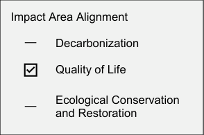
Indoor Environmental Quality Credit
ACCESSIBILITY AND INCLUSION
EQc3
1–2 points
INTENT
To support the diverse needs of occupants and increase widespread usability of the building to foster an individual and collective sense of belonging.
REQUIREMENTS
| Achievement pathways | Points |
|---|---|
Commercial Interiors | 1–2 |
Accessibility and Inclusion Strategies | 1–2 |
Comply with Local Accessibility Codes
Support access for those with physical disabilities by locating in a building that meets all locally applicable accessibility codes identified in the IPp2: Human Impact Assessment .
If there is no locally applicable code, the base building must include the following strategies:
-
Accessible routes or regularly used exterior building entrances must have ramps to accommodate elevation changes.
-
All doors meant for human passage from the main exterior building entrance to the project entrance have a minimum clear width of 32 inches (0.86 meters).
-
Reception desks, security counters, and service counters within the project boundary all have a front-approach, wheelchair-accessible section.
AND
Include at least 5 (1 point) or 10 (2 points) of the following accessibility and inclusion strategies that go beyond the locally applicable accessibility code and are most relevant to the project:
Accessibility for Physical Diversity
-
Provide wave-to-open or vertical hand/foot-press door operators at all regularly used building entrances.
-
Design meeting spaces to accommodate mobility devices for at least 10% of occupants.
U.S. Green Building Council LEED v5 Reference Guide for Interior Design and Construction, April 2025 Launch Edition 333
PDF Page 345
-
Incorporate accessible and inclusive equipment and activities in fitness facilities. Ensure an open and accessible route to and around the equipment.
- Where nonaccessible routes are provided (e.g., stairs), provide an alternate accessible route that starts and terminates at the same location.
Accessibility for Safety and Aging
-
Provide nonslip flooring.
-
Fix area rugs to the floor below and provide transition strips at all edges.
-
Provide a visual indication or a railing at all full-height glazing, except in private residences.
-
Provide audible and visual alerts for emergency alerts.
-
Provide closed risers (visually and physically) in all stairs.
-
Use visual contrast between walls and floors, walls and doors, and walls and casework.
-
Provide visual, tactile, contrasting, or photoluminescent warnings at floor level changes.
Accessibility for Social Health
-
Provide lactation rooms or pods.
-
Provide at least one fully accessible, all-gender, single-user restroom OR one multiuser, all-gender restroom on each floor of the building.
-
Include at least one adult changing station or table in a designated, accessible restroom or family restroom, or in one men’s and one women’s restroom.
-
Provide signage in all languages spoken by more than 5% of the local population.
-
Support neurodivergent users by achieving EQc: Occupant Experience, Option 1, Biophilic Environments, Path 1, Integrated Biophilic Design .
Accessibility for Navigation
-
Provide wayfinding signage that clearly indicates exits, entrances, and major functions in the project.
-
Provide nontext diagrams and symbols on signage.
-
Provide Braille, visual and auditory cues, and/or continuous linear indicators on paths of travel.
-
Use pattern and color blocking to identify key access spaces.
-
Provide haptic/tactile maps for wayfinding.
U.S. Green Building Council LEED v5 Reference Guide for Interior Design and Construction, April 2025 Launch Edition 334
PDF Page 346
REQUIREMENTS EXPLAINED
This credit encourages design that embraces the principles of accessibility and Inclusive Design, considering physical, sensory, and cognitive needs of occupants. [143] The goal is to go beyond basic accessibility measures to create environments that not only accommodate individuals with disabilities but also consider how all people interact, socialize, and move through spaces.
Comply with Local Accessibility Codes
All projects must ensure accessibility at a foundational level by demonstrating that the base building is in compliance with all relevant local accessibility codes identified in IPp2: Human Impact Assessment . If the project is located in a region with no accessibility code, the base building must demonstrate three foundational physical accessibility elements: ramps for accessible routes and entrances, clear width for human passage (from the main exterior entrance to the project entrance), and front-approach, wheelchair-accessible section. In these cases, including fully accessible restrooms on all floors within the project boundary is highly encouraged.
Ramps for accessible routes and entrances Ramps are required in and around buildings to provide accessibility for individuals with mobility impairments, as mandated by the Americans with Disabilities Act (ADA) [144] . Unlike solutions that require separate or specialized accommodations, integrated ramps allow people with mobility disabilities, as well as people with strollers, to use the same paths as other occupants, promoting dignity and inclusion through shared building circulation. Ramps must be present at primary entrances with steps to ensure at least one accessible entry point. Inside the base building, ramps are required where level changes exceeding 0.5 inches (12.7millimeters) occur within the path from the main building entrance to the project entrance, if elevators or lifts are not available. Emergency exits within the project boundary must also include ramps or accessible egress routes to support safe evacuation. All ramps must comply with ADA design standards, including proper slope, width, landings, handrails, and slip-resistant surfaces, ensuring they are safe and functional for all users.
Clear width for human passage From the main exterior entrance to the project entrance, projects must provide a minimum clear width of 32 inches (0.815 meters) at all doorways meant for human passage and 36 inches (0.915 meters) for circulation paths, with passing spaces of 60 inches (1.525 meters) provided at least every 200 ft. (61 meters) along any path less than 60 inches (1.525 meters) wide.
143 Zallio, M. & Clarkson, P, (2021, December), Inclusion, diversity, equity and accessibility in the built environment: A study of architectural design practice,https://www. sciencedirect.com/science/article/pii/S0360132321007496. 144 Americans with Disabilities Act (AD), https://www.ada.gov/
U.S. Green Building Council LEED v5 Reference Guide for Interior Design and Construction, April 2025 Launch Edition 335
PDF Page 347
Teams are strongly encouraged to consider a minimum clear doorway width of 36 inches (0.91 meters) for enhanced accessibility for all occupants.
Front-approach wheelchair-accessible section For all transaction surfaces within the project boundary, including reception desks and service counters, a front-approach, wheelchair-accessible section is required to promote height inclusivity and ensure individuals using wheelchairs can access and navigate spaces safely, efficiently, and with dignity.
Projects must demonstrate that the accessible portions of counters are no higher than 36 in. (0.914 meters) above the floor and at least 36 in. (0.914 meters) wide.
Accessibility and inclusion strategies Accessibility and inclusion strategies are organized into four categories: physical diversity, safety and aging, social health, and navigation. These strategies were selected based on research showing they provide the most significant benefits to the largest number of people, beyond what is most commonly required by local accessibility codes, including ADA.
Projects must include at least five (1 point) or 10 (2 points) of the following strategies. Findings from IPp2: Human Impact Assessment must be used to understand unique occupant needs to inform strategy selection. Do not select strategies that are present in the existing local code, unless the team demonstrates increased stringency.
If fewer than five strategies are relevant to the project due to project type variations, teams may submit up to two alternative inclusive design strategies that meet the intent of credit, for compliance.
Table 1. Accessibility for physical diversity strategies
| Accessibility for physical diversity | Examples, specifications, and explanation |
|---|---|
Wave-to-open or vertical hand/foot press door operators at all regularly used building entrances. | No-touch door activation devices accommodate a wide range of users, including those with mobility impairments, people carrying objects or children, and individuals with temporary injuries. Door activation devices at the entrance of the project may also be submitted for compliance. |
| Meeting spaces to accommodate mobility devices for at least 10% of occupants. | Accommodations include, but are not limited to, clear floor spaces and pathways of travel without obstruction. Users must be able to park mobility devices next to or within the seating area to avoid exclusion. |
| Accessible and inclusive equipment and activities in fitness facilities. AND Open and accessible route to and around the equipment. | Projects with fitness equipment and activities must be designed to accommodate a range of physical abilities. This includes providing an inclusive range of strength and stretching training equipment. |
U.S. Green Building Council LEED v5 Reference Guide for Interior Design and Construction, April 2025 Launch Edition 336
PDF Page 348
| Accessibility for physical diversity | Examples, specifications, and explanation |
|---|---|
A minimum clearance of 36 inches (0.915 meters) is the appropriate threshold for accessible routes between exercise equipment, as this aligns with_ADA_requirements for accessible paths and allows adequate space for wheelchair users to navigate between equipment. | |
| Alternate accessible route that starts and terminates at the same location for nonaccessible routes. | Directness and proximity of the accessible route are essential to maintain a similar level of convenience to the nonaccessible route. The alternative accessible route must be in the same general area as the circulation paths. As per_International Code Council (ICC),_ the maximum allowable difference between the start and end points of an accessible route and its nonaccessible counterpart is 200 feet (61 meters) in most indoor facilities, though it’s recommended to minimize this distance for those with mobility challenges—ideally to 100 feet (30 meters).145 |
Table 2. Accessibility for safety and aging
| Accessibility for safety and aging | Examples and explanations |
|---|---|
Nonslip flooring | Acceptable nonslip flooring includes, but is not limited to, textured tiles, rubber flooring, and epoxy-coated flooring providing slip resistance. |
| Fix area rugs to floor below and provide transition strips over high traffic areas. | Solutions include nonslip backing, double-side carpet tape, and rug gripper to keep the rug in place. Transition strips to smooth the connection between two different types of flooring materials are required in high traffic areas. |
| Provide visual indication or railings at all full height glazing, except in private residences. | Providing visual indicators, such as markers or patterns, will make it more noticeable for all users, including those with vision impairments. Adding railings at full-height glass also helps provide a physical barrier for people to easily detect and use for support, though not required. |
| Provide audible and visual alerts for emergency alerts. | Providing emergency alerts ensures that all users, including those with hearing or visual impairments, can respond to emergencies. This includes, but is not limited to, loud unique alarm sounds, voice announcements, flashing strobe lights, or LED beacons. |
| Provide closed risers (visually and physically) on all stairs. | Closed risers eliminate gaps; reduce the risk of tripping or falling, particularly for small children or pets; and make stairs more secure. In addition, closed risers also offer privacy and reassurance through a more solid visual structure. |
| Use visual contrast between walls and floors, walls and doors, and walls and casework. | Incorporating distinct visual contrast between different architectural elements improves navigation and wayfinding, particularly for individuals with visual impairments. Projects must use contrasting colors, textures, and/or material for walls, floors, doors, casework (i.e., drawers and cabinet doors), or other permanently installed features. |
| Provide visual, tactile, contrasting, or photoluminescent warnings at floor level changes. | Incorporate bold color contrasts or reflective strips to mark transitions, use textured materials such as ribbed or grooved strips to provide tactile cues, and apply varied |
145 International Code Council, (2017), 2017 ICC A117.1, Accessible and Usable Buildings and Facilities, https://www.codes.iccsafe.org/content/icca117-12017P4/chapter-4-accessible-routes.
U.S. Green Building Council LEED v5 Reference Guide for Interior Design and Construction, April 2025 Launch Edition 337
PDF Page 349
| Accessibility for safety and aging | Examples and explanations |
|---|---|
surface finishes to create both visual and tactile distinctions. Photoluminescent markings are recommended to be applied to ensure visibility in low-light conditions, particularly in staircases or emergency exit areas. | |
| Provide lactation rooms or lactation pods. | Dedicated lactation rooms, or breastfeeding support rooms, support higher rates of breastfeeding, improved work performance, and physical and emotional well-being.146 It is recommended that these rooms include features such as an electrical outlet, seating, and a table, along with access to a sink and refrigerator either within the room or on the same floor to better accommodate pumping and breastfeeding needs. |
| Provide at least one fully accessible, all-gender single-use restroom OR one multi-use all-gender restroom on each floor of the building. | Providing all-gender restrooms creates a more inclusive and welcoming environment for people who may prefer gender-neutral options.147 |
At least one adult changing station or table in a designated, accessible restroom or family restroom, or in each men’s and women’s restroom. | Locate the changing station in a family or accessible restroom that complies with ADA guidelines for door width, turning space (60 inches or 1.52 meters diameter), and clear floor area (30 x 48 inches or 0.76 x 1.22 meters). Use a height-adjustable adult changing table with a weight capacity of at least 350 lbs. (160 kg.) to accommodate diverse user needs. Ensure the table is at least 72 inches (1.83 meters) long and 30 inches (0.76 meters) wide for adequate space. |
| Provide signage in all languages spoken by more than 5% of the local population. | Ensure services and information are accessible to diverse communities. Provide additional signage for people with _limited English proficiency (LEP)_when they constitute 5% of the population or 1,000 individuals, whichever is smaller. |
Achieve at least one point under EQc2: Occupant Experience, Option 1. Biophilic Environments, Path 1. Integrated Biophilic Design | Biophilic design is particularly valuable for neurodivergent populations, approximately 15–20% of the global population.148 Achieve at least 1 point under_EQc2:_ Occupant Experience, Option 1. Biophilic Environments, Path 1. Integrated Biophilic Design. |
Table 3. Accessibility for navigation
| Accessibility for navigation | Examples and explanations |
|---|---|
Provide wayfinding signage that clearly indicates exits, entrances, and major functions in the project. | Signage should be clear, concise, and easy to understand, using both text and universally recognized symbols to accommodate individuals with varying levels of literacy. |
Provide nontext diagrams and symbols on signage. | Diagrams and symbols can convey instructions or warnings more quickly than text alone, making it easier for people with varying levels of literacy or visual impairments to understand. Provide alternative signage where applicable. |
146 De Souza, C. B., Venancio, S. I., & da Silva, R. P. G. V. C. (2021), Breastfeeding Support Rooms and Their Contribution to Sustainable Development Goals: A Qualitative Study, Frontiers in public health, 9, 732061, https://doi.org/10.3389/fpubh.2021.732061. 147 Harwood-Jones, M., Martin, K. & Airton, L. (2021, August), Research and Recommendations on Gender-Inclusive Washrooms and Changerooms, https://www.queensu.ca/hreo/sites/hreowww/files/uploaded_files/Washroom%20Report%20-%20Digital.pdf. 148 Doyle, N. (2020, October 14), Neurodiversity at work: a biopsychosocial model and the impact on working adults, https://www.pubmed.ncbi.nlm.nih.gov/32996572/.
U.S. Green Building Council LEED v5 Reference Guide for Interior Design and Construction, April 2025 Launch Edition 338
PDF Page 350
| Accessibility for navigation | Examples and explanations |
|---|---|
Provide Braille, visual and auditory cues, and/or continuous linear indicators on paths of travel. | Braille, along with visual and auditory cues or continuous linear indicators, enhances safety and usability for everyone, including those with vision impairments. |
Use pattern and color blocking to identify key access spaces. | Utilizing contrasting colors and unique patterns helps differentiate important spaces such as entrances, exits, and pathways, making them more recognizable and easier to navigate, particularly for the visually impaired. Provide visual contrast where applicable. |
DOCUMENTATION
| Project types | Options | Options/ Paths | Documentation |
|---|---|---|---|
All | All | Comply with Local Accessibility Codes | Confirmation of whether there is a locally applicable accessibility code for the project. |
All | All | Comply with Local Accessibility Codes | If the project has not met all locally applicable accessibility codes: contract documents highlighting the appropriate ramps, door widths, and front-approach, wheelchair- accessible counter sections. |
| Accessibility and Inclusion Strategies | Project Strategies (check, from the standard list in Requirements, which strategies have been implemented). | ||
| Accessibility and Inclusion Strategies | Narrative identifying locations in documents where project strategies are documented (file name, page number, at minimum). |
REFERENCED STANDARDS
-
American Disabilities Act (ADA) (ada.gov/law-and-regs/design-standards))
-
Occupational Safety and Health Administration (OSHA) (www.osha.gov/laws-regs)
U.S. Green Building Council LEED v5 Reference Guide for Interior Design and Construction, April 2025 Launch Edition 339
PDF Page 351
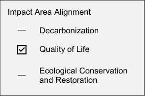
Indoor Environmental Quality Credit
RESILIENT SPACES
EQc4
1–3 points
INTENT
To support design features that increase the capacity for occupants to adapt to changing climate conditions and be protected from events that may compromise the quality of the indoor environment and, subsequently, occupant health and well-being.
REQUIREMENTS
| Achievement pathways | Points |
|---|---|
Commercial Interiors | 1–3 |
Option 1. Management Mode for Episodic Outdoor Ambient Conditions | 1 |
AND/OR | |
Option 2. Management Mode for Respiratory Diseases | 1 |
AND/OR | |
Option 3. Design for Occupant Thermal Safety During Power Outages | 1–2 |
Path 1. Consider Extreme Heat | 1 |
AND/OR | |
Path 2. Consider Extreme Cold | 1 |
AND/OR | |
Option 4. Operable Windows | 1–2 |
Comply with any of the following options for up to 2 points.
Option 1. Management Mode for Episodic Outdoor Ambient Conditions (1 point)
Design systems with the capability to operate an episodic outdoor event management mode as described in ASHRAE Guideline 44 . The mode should address varying outdoor conditions or events that could negatively influence indoor air quality, such as wildfire smoke. Include the management mode in the design and commissioning documents. Verify proper implementation of the mode during commissioning.
AND/OR
Option 2. Management Mode for Respiratory Diseases (1 point)
Design occupied spaces with the capability to operate an infection risk management mode that provides the minimum equivalent clean airflow rates outlined in ASHRAE 241-2023, Section 5.1. Include the management mode in the design and commissioning documents as outlined in
U.S. Green Building Council LEED v5 Reference Guide for Interior Design and Construction, April 2025 Launch Edition 340
PDF Page 352
ASHRAE 241-2023, Section B10.2 “Design Documentation.” Verify proper implementation of the mode during commissioning.
AND/OR
Option 3. Design for Occupant Thermal Safety During Power Outages (1–2 points)
PATH 1. CONSIDER EXTREME HEAT (1 POINT)
Demonstrate through thermal modeling that a building will passively maintain thermally habitable conditions during a power outage that lasts two days during peak summertime conditions of a typical meteorological year. Designate specific thermal safety zones where habitable conditions will be maintained during a power outage.
AND/OR
PATH 2. CONSIDER EXTREME COLD (1 POINT)
Demonstrate through thermal modeling or Passive House certification that a building will passively maintain thermally habitable conditions during a power outage that lasts two days during peak wintertime conditions of a typical meteorological year. Designate specific thermal safety zones where habitable conditions will be maintained during a power outage.
AND/OR
Option 4. Operable Windows (1–2 points)
Design 50% (for 1 point) or 75% (for 2 points) of the regularly occupied spaces to have operable windows with the capability to provide access to outdoor air during heat waves or localized power outages. The windows must meet the opening size and location requirements of ASHRAE 62.1-2022, Section 6.4.
REQUIREMENTS EXPLAINED
Incorporating resilient design solutions into our buildings increases the adaptive capacity of our communities, strengthening their capacity to respond to climate change and natural disasters.
This credit addresses a building’s ability to remain functional, maintain the quality of the indoor environment, and protect occupant health and well-being during major, episodic, disruptive events such as extreme weather conditions, wildfires, pandemics, or power outages. Although this credit addresses the design of events separately, teams are encouraged to consider and design for the possibility of multiple events occurring at the same time, such as a wildfire and extreme heat event.
U.S. Green Building Council LEED v5 Reference Guide for Interior Design and Construction, April 2025 Launch Edition 341
PDF Page 353
Leveraging information from IPp1: Climate Resilience Assessment and IPp2: Human Impact Assessment, select two strategies for up to two points. Teams can select any two options or paths, even those not identified as a high priority under IPp1: Climate Resilience Assessment .
Building Readiness Plans may be developed and communicated to facilitate operating in specialized modes only when necessary, and to educate building occupants on the transition from normal operations to management mode for the duration of the condition or event.
Option 1. Management Mode for Episodic Outdoor Ambient Conditions
Episodic outdoor ambient conditions can range from incidents such as the release of toxic chemicals outside a building to the widespread presence of wildfire smoke. Having an episodic outdoor event management mode facilitates the protection of building occupants from these and other outdoor pollution events.
System design for event management mode ASHRAE Guideline 44, Protecting Building Occupants from Smoke During Wildfire and Prescribed Burn Events [149] , specifies enhanced modes of operation to preserve IAQ during periods of heightened outdoor air pollution.
Refer to ASHRAE Guideline 44 to design HVAC systems capable of operating in a smoke-ready mode or other “event management mode.” Teams can leverage guidance from Standard 44 to design and apply similar modes of operation for any events that impact outdoor air quality including increases in nearby construction activity or chemical gas releases.
Commissioning requirements ASHRAE Guideline 44 prescribes testing HVAC systems in “smoke ready” conditions. Include the requisite sequences of operation in design documents and ensure that event management mode is included in the commissioning scope of work to verify that all equipment responds as intended.
Option 2. Management Mode for Respiratory Diseases
Following the COVID-19 pandemic, industry experts developed strategies to reduce airborne infectious disease transmission in buildings, for the protection of public health and to facilitate keeping buildings operational during periods of heightened risk. One resulting standard, ASHRAE Standard 241-2023, Control of Infectious Aerosols, specifies an infection risk
149 ASHRAE Guideline 44, Protecting Building Occupants from Smoke During Wildfire and Prescribed Burn Events, https://www.ashrae.org/about/news/2024/ashrae-releases-new-guidance-to-mitigate-the-impact-of-smoke-on-indoor-air-quality
U.S. Green Building Council LEED v5 Reference Guide for Interior Design and Construction, April 2025 Launch Edition 342
PDF Page 354
management mode with ventilation and filtration strategies for reducing occupant exposure to airborne pathogens that cause significant personal and economic damage each year.
Projects pursuing this option must design occupied spaces with the capability to operate in an Infection Risk Management Mode. This mode provides minimum equivalent clean airflow rates, calculated as the equivalent clean airflow rate per person multiplied by the anticipated number of people in a particular space. The building owner and facility manager must determine when to apply this mode of operation.
Commissioning requirements Include the requisite sequences of operation in design documents and ensure that Infection Risk Management Mode is included in the commissioning scope of work to verify that all equipment responds as intended.
Option 3. Design for Occupant Thermal Safety During Power Outages
During power outages, when backup power is unavailable, mechanical cooling, heating, and ventilation become inaccessible. Designing spaces to sustain thermal habitability passively or through manual occupant controls allows the building to remain livable until power is restored.
Projects that pursue Option 3 have two paths to consider: One for extreme cold and one for extreme heat. Based on the project’s location, teams should determine which option, or both, are appropriate.
Thermal safety zones Designate thermal safety zones where thermal habitability can be maintained during a loss of power. Analyze conditions on the assumption that building occupants will congregate in the safety zones during an outage. This may increase the expected occupant density above normal assumptions for the space. Include enough thermal safety zones so the occupant density does not exceed one person per 20 square feet (1.9 square meters).
Example An office building has 400 employees. If 20,000 square feet (1,858 square meters) of space is identified as being thermally safe, teams must analyze the space assuming 400 people will be in that 20,000 square feet (1,858 square meters) area.
A 20,000 square feet (1,858 square meters) zone can accommodate up to 1,000 people. Therefore, the project would meet the sizing requirements.
U.S. Green Building Council LEED v5 Reference Guide for Interior Design and Construction, April 2025 Launch Edition 343
PDF Page 355
Thermal habitability Define habitable conditions as applicable to the project type. Thermally safe conditions may differ from a healthcare facility to a typical office building. For example, the heat stress index for an office building will be different than a nursing home. Consider the project type and the population when performing the initial analysis. Thermal habitability is not thermal comfort, and will therefore be different than the comfort zone prescribed in ASHRAE Standard 55 .
Natural ventilation Thermal safety zones must have access to natural ventilation. This is achievable through operable windows, doors, operable panels, or louvers.
Thermal models Thermal models analyze heat transfer within a building, accounting for climate, insulation, glazing specifications, solar gains, envelope leakage rates, and ventilation. Use computer simulation software to perform the thermal modeling for each path, based on project-specific inputs. Consider using modeling tools that are approved for Passive House compliance.
The analysis uses a two-day period. This was selected as an entry-level duration for LEED projects for design purposes. A four-day period has been used previously in the LEED v4 pilot credit Passive Survivability and Back-up Power During Disruptions. A time frame of 72 hours (3 days) is often used for general emergency preparedness planning (such as disaster-ready kits). Extreme heat or cold periods can last longer than two days; for example, according to the U.S. EPA using heat wave tracking data by the National Oceanic and Atmospheric Administration (NOAA), the average heat wave in major U.S. urban areas has been about four days long. [150]
PATH 1. CONSIDER EXTREME HEAT
Demonstrate with a thermal model that the building will passively maintain habitable conditions for at least two days during a power outage in hot, summer months. The two-day period must represent the peak summertime conditions of a typical meteorological year (TMY).
AND/OR
PATH 2. CONSIDER EXTREME COLD
Demonstrate with a thermal model or through Passive House certification that the building will passively maintain habitable conditions for at least two days during a power outage in cold, winter months. The two-day period must represent the peak wintertime conditions of a TMY.
150 EPA, Climate Change Indicators, https://www.epa.gov/climate-indicators/climate-change-indicators-heat-waves#ref6.
U.S. Green Building Council LEED v5 Reference Guide for Interior Design and Construction, April 2025 Launch Edition 344
PDF Page 356
Option 4. Operable Windows
During a power outage, ventilation may rely on operable windows, doors, or other openings to maintain airflow. Operable windows can also be utilized for thermal comfort depending on outside weather conditions and may minimize reliance on building systems and support adaptability for future changes in building use.
DOCUMENTATION
| Project types | Options | Paths | Documentation |
|---|---|---|---|
All | Option 1. Management Mode for Episodic Outdoor Ambient Conditions | All | Design documents confirming management mode design and sequence of options. |
All | Option 1. Management Mode for Episodic Outdoor Ambient Conditions | All | Final Commissioning Report, confirming that management mode was tested during commissioning. |
All | Option 2. Management Mode for Respiratory Diseases | All | Design documents confirming management mode design and sequence of options. |
All | Option 2. Management Mode for Respiratory Diseases | All | Final Commissioning Report, confirming that management mode was tested during commissioning. |
All | Option 3. Design for Occupant Thermal Safety During Power Outages | Path 1 and Path 2 | Thermal model report and results and identify thermal safety zones. |
All | Option 4. Operable Windows | All | ASHRAE Standard 62.1 calculations for opening areas and distances for all regularly occupied spaces. |
All | Option 4. Operable Windows | All | Percentage of spaces with operable windows. |
REFERENCED STANDARDS
-
ASHRAE Guideline 44 (store.accuristech.com/ashrae/standards/guideline-44-2024- protecting-building-occupants-from-smoke-during-wildfire-and-prescribed-burn- events?product_id=2923808)
-
ASHRAE 241-2023 (store.accuristech.com/ashrae/standards/ashrae-241- 2023?product_id=2567398)
U.S. Green Building Council LEED v5 Reference Guide for Interior Design and Construction, April 2025 Launch Edition 345
PDF Page 357
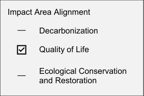
Indoor Environmental Quality Credit
AIR QUALITY TESTING AND MONITORING
EQc5
1–4 points
INTENT
To support better management of IAQ and identify opportunities for health-based approaches to building operations.
REQUIREMENTS
| Achievement pathways | Points |
|---|---|
Commercial Interiors | 1–4 |
Option 1. Preoccupancy Air Testing | 1–2 |
Path 1. Particulate Matter and Inorganic Gases | 1 |
AND/OR | |
Path 2. Volatile Organic Compounds | 1 |
AND/OR | |
Option 2. Continuous Indoor Air Monitoring | 1 |
Option 1. Preoccupancy Air Testing (1–2 points)
After construction ends and before occupancy, but under ventilation conditions typical for occupancy, conduct baseline IAQ testing. Retail projects may conduct the testing within 14 days of occupancy. The number of measurements should be specified according to Table 1 and taken in respective locations of the building.
Table 1. Number of measurements required for preoccupancy air testing
| Total occupied floor area, sq. ft (sq. m.) | Number of measurements |
|---|---|
| ≤ 5,000 (500) | 1 |
| > 5,000 (500) and ≤ 15,000 (1,500) | 2 |
| > 15,000 (1,500) and ≤ 25,000 (2,500) | 3 |
| > 25,000 (2,500) and ≤ 200,000 (20,000) | 4 plus one additional measurement per each 25,000 sq. ft. (2,500 sq. m.) above 25,000 sq. ft. |
U.S. Green Building Council LEED v5 Reference Guide for Interior Design and Construction, April 2025 Launch Edition 346
PDF Page 358
| Total occupied floor area, sq. ft (sq. m.) | Number of measurements |
|---|---|
| > 200,000 (20,000) | 10 plus one additional measurement per each 50,000 sq. ft. (4,600 sq. m.) above 200,000 sq. ft. |
PATH 1. PARTICULATE MATTER AND INORGANIC GASES (1 POINT)
Test for the particulate matter (PM) and inorganic gases listed in Table 2, using an allowed test method, and demonstrate that the contaminants do not exceed the concentration limits listed in the table. Measure for a four-hour period, calculating peak concentration for carbon monoxide and average concentration for ozone, PM2.5, and PM10.
Table 2. Limits for particulate matter and inorganic gases
| Contaminant (CAS#) | Concentration limit (µg/m3) | Allowed test methods (laboratory-based) | Direct reading instrument minimum specifications |
|---|---|---|---|
| Carbon monoxide (CO) | 9 ppm; no more than 2 ppm above outdoor levels | ISO 4224 EPA Compendium Method IP-3 GB/T 18883-2002 for projects in China | Direct calibrated electrochemical instrument with accuracy of +/– 3% of reading and resolution of 0.1 ppm NDIR CO sensors with accuracy of 1% of 10 ppm full scale and display resolution of less than 0.1 ppm |
| Particulates (for projects in attainment areas) | ISO class 8 or lower per ISO 14644-1:2015 OR meet PM10: 50 μg/m3 PM2.5: 12 μg/m3 | n/a | Accuracy (+/–): Greater of 5 μg/m3 or 20% of reading Resolution (+/–): 5 μg/m3 |
| Particulates (for projects in attainment areas) | ISO class 8 or lower per ISO 14644-1:2015 OR meet PM10: 50 μg/m3 PM2.5: 12 μg/m3 | IP-10A | IP-10A |
| Particulates (for projects in nonattainment areas) | I_SO_ class 8 or lower per ISO 14644-1:2015 OR meet PM10: 50 μg/m3 PM2.5: 35 μg/m3 | n/a | Accuracy (+/–): Greater of 5 μg/m3 or 20% of reading Resolution (+/–): 5 μg/m3 |
| Particulates (for projects in nonattainment areas) | I_SO_ class 8 or lower per ISO 14644-1:2015 OR meet PM10: 50 μg/m3 PM2.5: 35 μg/m3 | IP-10A | IP-10A |
| Ozone | 0.07 ppm | ISO 13964 ASTM D5149-02 | Monitoring device with accuracy greater of 5 |
U.S. Green Building Council LEED v5 Reference Guide for Interior Design and Construction, April 2025 Launch Edition 347
PDF Page 359
| Contaminant (CAS#) | Concentration limit (µg/m3) | Allowed test methods (laboratory-based) | Direct reading instrument minimum specifications |
|---|---|---|---|
| OR 0.01 ppm for projects pursuing_EQc: Enhanced_ Air Quality, Option 1, Path 2 | EPA-designated methods for ozone | ppb or 20% of reading and resolution (5 min average data) +/– 5 ppb |
AND/OR
PATH 2. VOLATILE ORGANIC COMPOUNDS (1 POINT)
- Perform a screening test for total volatile organic compounds (TVOC). Use ISO 16000-6, EPA TO-17, or EPA TO-15 to collect and analyze the air sample. Calculate the TVOC value per EN 16516:2017 ; California Department of Public Health Standard Method v1.2 2017, Section 3.9.4 ; or an alternative calculation method, as long as the full method description is included in the test report.
o If the TVOC levels exceed 500 µg/m [3], investigate for potential issues by comparing
the individual VOC levels from the GC/MS results to associated cognizant authority health-based limits. Correct any identified issues and retest if necessary.
- Test for the individual VOCs listed in Table 3 using an allowed test method and demonstrate that the contaminants do not exceed the concentration limits listed in the table. Laboratories that conduct the tests must be accredited under ISO/IEC 17025 for the test methods they use.
U.S. Green Building Council LEED v5 Reference Guide for Interior Design and Construction, April 2025 Launch Edition 348
PDF Page 360
Table 3. Volatile organic compound limits
| Contaminant (CAS#) | Concentration limit (µg/m3) | Allowed test methods |
|---|---|---|
| Formaldehyde 50-00-0 | 20 µg/m3 (16 ppb) | ISO 16000-3, 4; EPA TO-11a; EPA comp. IP-6A; ASTM D5197-16 |
| Acetaldehyde 75-07-0 | 140 µg/m3 | 140 µg/m3 |
| Benzene 71-43-2 | 3 µg/m3 | ISO 16000-6; EPA IP-1; EPA TO-17; EPA TO-15; ISO 16017-1, 2; ASTM D6196-15 |
| Hexane (n-) 110-54-3 | 7,000 µg/m3 | 7,000 µg/m3 |
| Naphthalene 91-20-3 | 9 µg/m3 | 9 µg/m3 |
| Phenol 108-95-2 | 200 µg/m3 | 200 µg/m3 |
| Styrene 100-42-5 | 900 µg/m3 | 900 µg/m3 |
| Tetrachloroethylene 127-18-4 | 35 µg/m3 | 35 µg/m3 |
| Toluene 108-88-3 | 300 µg/m3 | 300 µg/m3 |
| Vinyl acetate 108-05-4 | 200 µg/m3 | 200 µg/m3 |
| Dichlorobenzene (1,4-) 106-46-7 | 800 µg/m3 | 800 µg/m3 |
| Xylenes—total 108-38-3, 95-47- 6, and 106-42-3 | 700 µg/m3 | 700 µg/m3 |
AND/OR
Option 2. Continuous Indoor Air Monitoring (1 point)
Provide indoor air monitors for all of the following parameters:
-
Carbon dioxide (CO2)
-
Particulate matter (PM2.5)
-
Total volatile organic compounds (TVOC)
-
Temperature
-
Relative humidity
Monitors must be building grade or better and located between 3 and 6 feet (1–2 meters) above the floor.
REQUIREMENTS EXPLAINED
This credit helps the project gain a better understanding of their indoor air.
U.S. Green Building Council LEED v5 Reference Guide for Interior Design and Construction, April 2025 Launch Edition 349
PDF Page 361
The pre-occupancy testing provides this insight prior to building use to prevent occupant exposure to unsatisfactory air. Continuous indoor air monitoring provides this understanding throughout operations, to track contaminant levels over time and to proactively identify any issues and faults.
Teams may utilize both options for a total of two points and may find it beneficial to perform air testing prior to occupancy at the same time as setting up the continuous monitoring systems.
Option 1. Pre-occupancy Air Testing
Construction activities and building materials can introduce contaminants that may negatively affect a building’s IAQ . Testing after construction incentivizes the contractors to follow construction management practices in accordance with EQp1: Construction Management and follow low-emitting material specifications. It also verifies that the indoor environment is acceptable for human occupancy and ensures that ventilation systems are effectively maintaining adequate IAQ .
Number of measurements The number of measurement points required is outlined in Table 1 of the rating system. The table provides a consistent number of measurements per floor area (square feet or square meters) to help with planning for testing and the associated costs.
The floor area in Table 1 reflects the total occupied floor area for the project, including all regularly and nonregularly-occupied areas. For example, corridors are nonregularly-occupied and must be included in the total area for this calculation. Unoccupied areas, such as mechanical and electrical rooms, are excluded.
Projects may choose to test take more measurements beyond the minimum if desired. Exceeding the minimum number of measurements does not earn additional points but will provide a more comprehensive assessment of the IAQ.
Measurement locations Measurement locations must be selected to best represent the project occupancy and function(s). Use the following criteria to determine representative locations for the project:
-
Regularly occupied spaces . Prioritize regularly occupied spaces. Non-regularlyoccupied spaces must be included in the total area for determining the occupied floor area, but need not be tested.
-
Multiple space types . If more than one measurement is necessary per Table 1., test multiple space types. For example, in an office building, test open office spaces, but also
U.S. Green Building Council LEED v5 Reference Guide for Interior Design and Construction, April 2025 Launch Edition 350
PDF Page 362
consider closed offices, conference rooms, quiet space, and other occupied space types. In a school building, test classroom space, but also consider the auditorium, administrative offices, student assembly areas and lab spaces.
-
Different ventilation systems . If the project has multiple ventilation systems, identify a measurement location in areas served by each ventilation system, up to the required number of measurement points.
-
Multiple floors . For projects with multiple floors, select locations on different floors.
-
Spaces where the highest concentrations of contaminants are likely to occur . This could be due to the construction or fit-out of the space, or a lower ventilation rate. For example, private offices may have a higher concentration of contaminants compared to open offices, due to a higher density of furniture and finish materials in an enclosed space.
Failed testing If a test fails, take corrective action (e.g., clean and flush out the space) and retest. All test locations must meet the concentration limits in Table 2 for Path 1 compliance and/or Table 3 for Path 2 compliance.
Timing for air quality testing Air quality measurements must be conducted after construction is complete and before occupancy. For the purposes of this credit, construction is complete once all furniture and finishes are installed, construction punch-list items that would generate VOCs or other contaminants are complete, and testing and balancing of the HVAC system has been conducted.
Testing must be done under normal operating ventilation conditions. If there are unoccupied setbacks in the ventilation system, test during normal occupied hours to achieve the typical ventilation conditions.
All testing and retesting must be completed before occupancy.
Retail projects Retail projects may perform testing within 14 days of occupancy. This is to accommodate the unique compressed construction timeline for typical retail projects.
PATH 1. PARTICULATE MATTER AND INORGANIC GASES
Each location must be tested for all contaminants in Table 2 of the Rating System.
Table 2 outlines the approved test methods for each contaminant. Teams can use laboratorybased testing or take measurements using direct-reading instruments. If using direct readings,
U.S. Green Building Council LEED v5 Reference Guide for Interior Design and Construction, April 2025 Launch Edition 351
PDF Page 363
all instruments must meet the minimum specifications of Table 2. Alternative methods may be used for Path 1 contaminants if the project team documents that the accuracy and resolution specifications in Table 2 are met.
PATH 2. VOLATILE ORGANIC COMPOUNDS
A screening test for TVOC and test for each individual VOC in Table 3 must be performed at each measurement location.
Because VOC testing and analysis is complex, it must be performed using specific methods by a laboratory that is accredited under ISO/IEC 17025 [151] for the test method used.
TVOC screening is intended to serve as a general indicator of the VOC levels in the building and is used to capture situations where investigation of individual VOCs beyond those targeted via Table 3. of the rating system may be needed. While projects are not required to meet a specific TVOC threshold, they are required to report TVOC results. If the TVOC concentration exceeds 500 ug/m3, the team must work with the laboratory to compare the individual VOC levels from the GC/MS results to associated cognizant health-based limits and perform corrective actions as necessary.
Option 2. Continuous Indoor Air Monitoring
During occupancy, airborne contaminants can enter a building from the outdoors or be introduced by indoor sources and activities such as cleaning, cooking, use of candles, 3D printers, or improperly vented heating appliances. Permanently installed continuous indoor air monitors enable the identification of potential issues and timely corrective actions to assure systems designed to maintain IAQ in the building continue to work as intended through the project’s operational phase.
Number of monitors A successful monitoring strategy must consider the data collection purpose and dedicated resources for ongoing data management. Fewer well-managed monitors are usually more beneficial than numerous neglected monitors. Include at least one monitor per 25,000 feet (2,500 square meters) of total occupied floor area. This density is a good entry point for getting started with IAQ monitoring. Additional monitors can be added as desired up to the best-practice density of one monitor per 5,000 square feet (500 square meters) of total occupied floor area.
151 ISO/IEC 17025, https://www.iso.org/ISO-IEC-17025-testing-and-calibration-laboratories.html
U.S. Green Building Council LEED v5 Reference Guide for Interior Design and Construction, April 2025 Launch Edition 352
PDF Page 364
Monitor locations Monitors must be placed to best represent the project occupancy and function(s). This will vary depending on the purpose of the monitoring. Use the following criteria to determine representative locations for the project:
-
Multiple space types . Consider including monitors in multiple space types. For example, in an office building, monitor the open office spaces, but also consider closed offices, conference rooms, quiet spaces, and other occupied space types. In a school building, monitor classroom spaces, but also consider the auditorium, administrative offices, student assembly areas and lab spaces.
-
Different ventilation systems . If the project has multiple ventilation systems, consider placing monitors in areas served by each ventilation system.
-
Multiple floors . For projects with multiple floors, consider placing monitors on different floors.
-
Spaces where the highest concentrations of contaminants are likely to occur . This could be due to the construction or fit-out of the space, a lower ventilation rate or air filtration level, the presence of combustion or operable windows, or occupant activities. For example, cafeterias may have a higher concentration of contaminants compared to classrooms, due to the presence of cooking.
-
Spaces occupied by at-risk populations or spaces designated for cleaner air . Consider placing monitors in areas where people who are more susceptible to poor IAQ congregate. For example, this may include spaces with infants, children, pregnant women, acute care facilities, and assisted living facilities.
If monitoring to support IAQ management during wildfires and prescribed burn events, review ASHRAE Guideline 44, Section 5.5.1.2 for considerations for monitor placement.
Monitors must be permanently installed at a height corresponding to the breathing zone of a typical occupant. In most situations, the breathing zone is 3–6 feet (0.9–1.8 meters) above finished floor height, based on the location of an occupant’s head when seated or standing. Alternative mounting heights based on the anticipated occupant position in a space may be considered.
Where possible, place monitors at least 3 feet (0.9 meters) away from doors, windows, air filters, air supply outlets, exhaust intakes, stoves, printers, and other potential airborne contaminant sources or sinks. In areas where this is not possible, locate monitors closer to air returns than air diffusers.
Monitors located in ducts do not meet the requirements.
U.S. Green Building Council LEED v5 Reference Guide for Interior Design and Construction, April 2025 Launch Edition 353
PDF Page 365
Monitor specifications Select indoor air monitoring devices that measure carbon dioxide (CO2), fine particulate matter (PM2.5), TVOC , temperature, and relative humidity. Monitors must meet the building grade requirements of RESET Grade B [152] or UL 2095 Grade B.
Hourly reporting Monitors must report hourly (or higher frequency including 15-minute data for CO2) data to a remote location that logs pollutant levels over time.
A digital display, or integration with the BMS, is not required to achieve the credit.
Table 1. RESET Grade B monitor specifications
| RESET Grade B monitor specifications | CO2 | PM2.5 | TVOC | Temperature | Relative humidity |
|---|---|---|---|---|---|
Data loss | 10% | 10% | 10% | 10% | 10% |
Operating range for Temperature | 0-40 | 0-40 | 0-40 | 0-40 | 0-40 |
Operating range for Relative Humidity | 10-80 % RH non-condensing | 10-80 % RH non-condensing | 10-80 % RH non-condensing | 10-80 % RH non-condensing | 10-80 % RH non-condensing |
Data Output Interval | 5 min | 5 min | 5 min | 5 min | 5 min |
Sampling type | Active airflow | ||||
Sensor Output Resolution | 5 ppm | 1 μg/m3 | 4.4 ppb | 0.1 | 1 % RH |
Measuring Range | 400-5000 ppm | 0-500 μg/m3 | 65-870 ppb | 0-40 | 10-80 % RH |
| Accuracy* | 400–2000 ppm : ±50 && 3% 2000 - 5000 : ±50 && 5% | 0 - 150 : ±5 && 15% 150 - 500 : ±5 && 20% | 65–260 ppb : ±8.7 && 15% 260 - 870 : ±8.7 && 20% | ±1~~℃~~ | ±8% RH |
| Performance Check and Re- calibration | Required | Required | Required | Required | Required |
*Example for interpreting the accuracy requirement: If a reference monitor is reading 900 ppm, a Grade B monitor’s reading must read within 50 + (0.03 x 900) = ±77. The Grade B monitor’s reading must be between 823 and 977 ppm
152 RESET Indoor Air Quality Monitors, https://www.reset.build/directory/monitors/type/indoor.
U.S. Green Building Council LEED v5 Reference Guide for Interior Design and Construction, April 2025 Launch Edition 354
PDF Page 366
DOCUMENTATION
| Project types | Options | Paths | Documentation |
|---|---|---|---|
All | Option 1. Pre- occupancy air testing | Path 1 and Path 2 | Completed air quality testing report, including time, date, testing methods complying with credit requirements, results and limits of the tested contaminants in all locations, and lab accreditation scope for Path 2 VOCs if applicable. |
All | Option 1. Pre- occupancy air testing | Path 1 and Path 2 | Evidence of testing locations. |
All | Option 1. Pre- occupancy air testing | Path 1 and Path 2 | Document confirming substantial completion of construction, highlighting the date. The intent is to confirm that construction was complete prior to the time/date of the air quality testing. |
All | Option 2. Continuous Indoor Air Monitoring | All | Evidence of monitoring locations and description of monitoring approach. |
All | Option 2. Continuous Indoor Air Monitoring | All | Specifications of building grade air monitors. |
REFERENCED STANDARDS
-
EPA Compendium Method IP-3, GB/T 18883-2002 (nepis.epa.gov/Exe/ZyPURL.cgi?Dockey=30003ULE.txt)
-
EPA designated methods for Ozone (epa.gov/system/files/documents/2024-12/amtic-list- december-2024_final.pdf)
-
ISO IEC 17025 (iso.org/ISO-IEC-17025-testing-and-calibration-laboratories.html)
-
CDPH Standard Method v1.2-2017 (cdph.ca.gov/Programs/cls/dehl/ehl/Pages/AQS/VOCs.aspx)
-
Reset Air Accredited Monitors (reset.build/directory/monitors)
-
UL 2905 (shopulstandards.com/ProductDetail.aspx?productId=ULE2905_2_S_20230110)
U.S. Green Building Council LEED v5 Reference Guide for Interior Design and Construction, April 2025 Launch Edition 355
PDF Page 367
PROJECT PRIORITIES (PR)
OVERVIEW
The historical Innovation credit category has evolved in LEED v5 to become the Project Priorities (PR) credit category. The goal is greater flexibility for projects to address their unique context and priorities, including typology, culture, location, areas of innovation, and individual performance objectives. Credits can be added to the library as they are developed, enabling an adaptive and agile response to rapidly evolving industry knowledge, developing technologies, and emerging innovative solutions. In addition, projects are empowered to pursue improvements that are most meaningful to their specific goals and circumstances.
For example, the evolution of the building industry over the last 15 years has fostered a need for more sector-specific sustainability metrics. Additionally, greater adoption of reporting has prompted real estate organizations to establish targets in areas including decarbonization, occupant health, and biodiversity. The PR credit category aims to provide recognition for projects pursuing these goals outside of the established credits in LEED v5 .
New metrics and strategies can be continually applied to LEED without waiting for the next version to debut, allows for a more nimble and dynamic development of credits and compliance paths in between releases of new rating system versions.
By embracing flexibility and encouraging continuous innovation, the PR credit category ensures that LEED remains a dynamic tool for advancing sustainability. It empowers project teams to align their efforts with evolving best practices, sector-specific goals, and emerging global challenges, ensuring that buildings remain resilient, forward-thinking, and impactful over time.
U.S. Green Building Council LEED v5 Reference Guide for Interior Design and Construction, April 2025 Launch Edition 356
PDF Page 368
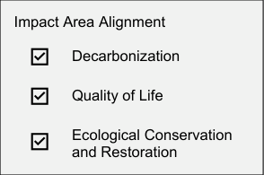
Project Priorities Credit
PROJECT PRIORITIES
PRc1
1–9 points
INTENT
To promote the achievement of credits that address geographically sensitive or adaptationspecific environmental, social equity, and public health priorities. To encourage projects to think creatively to test and accelerate new sustainable building practices and strategies.
REQUIREMENTS
| Achievement pathways | Points |
|---|---|
Commercial Interiors | 1–9 |
Regional Priority | 1–9 |
Project-Type Credits | Project-Type Credits |
Exemplary Performance | Exemplary Performance |
Pilot Credits | Pilot Credits |
Innovation Strategies | Innovation Strategies |
Achieve any combination of the following for a maximum of 9 points:
Regional priority Achieve a regional priority credit from USGBC’s Project Priority Library. These credits have been identified by USGBC as having additional regional importance for the project’s region.
Project-type credits Achieve a project-type credit from USGBC’s Project Priority Library. These credits have been identified by USGBC as addressing unique needs for the given adaptation or building application.
Exemplary performance Achieve an exemplary performance credit from USGBC’s Project Priority Library. These credits have been identified by USGBC as going above and beyond an existing LEED v5 prerequisite or credit in the LEED v5 priority areas of scale, decarbonization, resilience, health, equity, and/or ecosystems.
Pilot credits Achieve a pilot credit from USGBC’s Project Priority Library.
U.S. Green Building Council LEED v5 Reference Guide for Interior Design and Construction, April 2025 Launch Edition 357
PDF Page 369
Innovative Strategies Achieve significant, measurable, environmental performance using a strategy not addressed in the LEED green building rating system.
Identify all of the following:
-
The intent of the proposed innovation strategy
-
Proposed requirements for compliance
-
Proposed submittals to demonstrate compliance
-
The design approach or strategies used to meet the requirements
REQUIREMENTS EXPLAINED
Teams earn recognition for implementing innovative measures addressing distinct focus areas in their projects through the Project Priorities credit. This credit offers multiple pathways for projects to address their respective priorities and go beyond the requirements listed in other LEED credits. This flexibility enables teams to effectively address the distinct needs of their projects, fostering innovation and adaptability. Each project can chart its path forward based on its own goals. [153]
Projects prioritize efforts based on their unique contexts. Teams can choose the best credits for addressing their project’s goals and targets. Some projects may concentrate most of their effort toward a single priority area, including priorities specific to that project type or to exemplary performance. Other projects might choose to address different priority areas more uniformly. For example, an office building in a coastal city prone to hurricanes and flooding might prioritize enhancing resilience to regional climate challenges with applicable credit pathways focused on flood mitigation, building safety, and reinforced construction materials and design. Similarly, an urban mixed-use development comprising residential and commercial spaces might have a variety of sustainable priorities to address, such as incorporating renewable energy efficiency, providing indoor environmental quality to building tenants, and promoting methods for active or cleaner forms of transportation.
To achieve the maximum nine points available, project teams should incorporate as many credits under each pathway as they prefer, using any combination of project type credits, exemplary performance credits, regional priorities, innovation strategies, and pilot credit pathways.
153 Green buildings. (n.d.). PNNL. https://www.pnnl.gov/explainer-articles/green-buildings
U.S. Green Building Council LEED v5 Reference Guide for Interior Design and Construction, April 2025 Launch Edition 358
PDF Page 370
Project type Achieve a project-type credit from the USGBC’s Project Priority Library . USGBC has identified these credits as addressing unique needs for the given adaptation or building application.
Example strategies: Project type A data center project might focus on project-type credits specific to data centers that address energy efficiency, advanced cooling technologies, and renewable energy integration.
Exemplary performance Achieve exemplary performance requirements of an existing LEED v5 credit eligible for exemplary performance, as specified in USGBC’s Project Priority Library. Exemplary performance earns points by exceeding the credit requirements or achieving the next incremental percentage threshold for the credit.
Regional priority Identify the environmental and/or social equity and/or public health priorities for the project’s location and achieve LEED credits that address those regional priorities. Regional Priority credits address geographically specific environmental and/or social priorities for the project’s region.
Innovation strategies Achieve innovation credits from the USGBC’s Project Priority Library. Alternatively, achieve innovation credits by adopting new strategies not addressed in the LEED rating system that demonstrate reduced environmental impacts, increased decarbonization, and improved social impacts. Projects will need to submit documentation that identifies the intent of the proposed innovation credit, proposed requirements for compliance, proposed submittals to demonstrate compliance, and the design approach or strategies used to meet the requirements.
Pilot credits Achieve pilot credits from the USGBC’s Project Priority Library. USGBC has identified these credits to explore new aspects of sustainable design, building, and construction and potentially include in future additions of the LEED rating system.
U.S. Green Building Council LEED v5 Reference Guide for Interior Design and Construction, April 2025 Launch Edition 359
PDF Page 371
DOCUMENTATION
| Project types | Options/ Paths | Required for upload | Documentation |
|---|---|---|---|
All | Project type | Description | Project type narrative. |
All | Project type | Documentation | Project type submittals. |
All | Exemplary performance | N/A | Exemplary performance credit and threshold are documented in the credit pursuing an EP point. |
All | Regional priority | Description | Narrative describing regional priorities. |
All | Innovation strategies | Description | Narrative describing the innovation, including details. |
All | Innovation strategies | Documentation | Any documentation, including calculations, submittals, case studies, etc. that supports the innovation strategy. |
All | Pilot credit | Registration | Upload confirmation that the project is registered for a pilot credit. |
All | Pilot credit | Survey | Complete and upload the pilot credit survey. |
All | Pilot credit | Submittals | Complete and upload all pilot credit submittals. |
REFERENCED STANDARDS
- None
U.S. Green Building Council LEED v5 Reference Guide for Interior Design and Construction, April 2025 Launch Edition 360
PDF Page 372
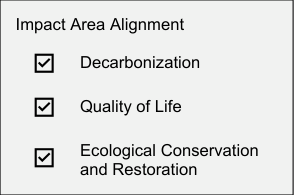
Project Priorities Credit
LEED AP
PRc2
1 point
INTENT
To encourage team integration required by a LEED AP and to streamline the application and certification process.
REQUIREMENTS
| Achievement pathways | Points |
|---|---|
Commercial Interiors | 1 |
LEED AP | 1 |
At least 1 principal participant of the project team must be a LEED AP with a specialty appropriate for the project.
REQUIREMENTS EXPLAINED
The credit rewards projects that include a LEED AP with an active credential on the project team at the time of certification review.
A key design team member must have a LEED AP with LEED AP ID+C: Commercial Interiors specialty. While all LEED AP credentials provide an understanding of the green building community and certification requirements, team members with the LEED AP ID+C specialty have extensive knowledge and experience with the prerequisites and credits for a Commercial Interiors project.
LEED APs without specialty do not qualify for this credit.
U.S. Green Building Council LEED v5 Reference Guide for Interior Design and Construction, April 2025 Launch Edition 361
PDF Page 373
DOCUMENTATION
| Project types | Options/ Paths | Required for upload | Documentation |
|---|---|---|---|
All | All | (open-ended inputs) | Full name of LEED AP with specialty. |
All | All | (open-ended inputs) | Specialty credential of the LEED AP. |
All | All | (open-ended inputs) | GBCI Credential Number. |
REFERENCED STANDARDS
- None
U.S. Green Building Council LEED v5 Reference Guide for Interior Design and Construction, April 2025 Launch Edition 362
PDF Page 374
APPENDIX I: LEED PLATINUM REQUIREMENTS
EAc1: Electrification Do not install new on-site combustion equipment in the project scope of work.
EAc2: Enhanced Energy Efficiency Seven points are required.
EAc3: Renewable Energy 100% of tenant annual site energy consumption is from any combination of Tier 1, Tier 2, and Tier 3 renewable energy.
MRc2: Reduce Embodied Carbon 10% reduction in embodied carbon.
U.S. Green Building Council LEED v5 Reference Guide for Interior Design and Construction, April 2025 Launch Edition 363
PDF Page 375

ISBN # 979-8-99251 10-1-7 usgbc.org